


SSB RADIOTELEPHONE
FS-1570 (150 W)
FS-2570 (250 W)

9-52 Ashihara-cho,9-52 Ashihara-cho,
A
A
*00080933800**00080933800*
*00080933800**00080933800*
*OME56360B00**OME56360B00*
Nishinomiya, JapanNishinomiya, Japan
Telephone :Telephone : 0798-65-21110798-65-2111
Telefax :Telefax : 0798-65-42000798-65-4200
Your Local Agent/DealerYour Local Agent/Dealer
ll rights reserved.
ll rights reserved.
PUB.No.PUB.No. OME-56360OME-56360
(( DAMIDAMI ))
FS-1570/2570FS-1570/2570
Printed in JapanPrinted in Japan
FIRST EDITION :FIRST EDITION : OCT.OCT. 20022002
B :B : OCT.OCT. 18,200218,2002
* 0 0 0 8 0 9 3 3 8 0 0 ** 0 0 0 8 0 9 3 3 8 0 0 *
*OME56360B00**OME56360B00*
* O M E 5 6 3 6 0 B 0 0 ** O M E 5 6 3 6 0 B 0 0 *
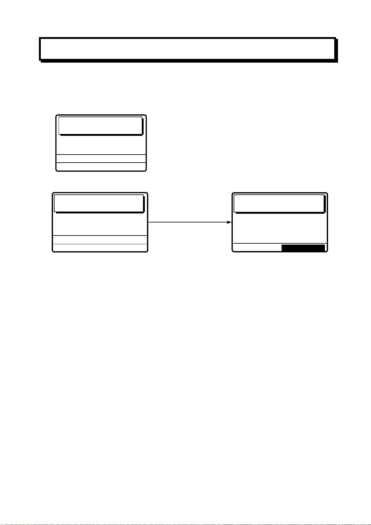
Distress Alert Calling Procedure
Below is the procedure for transmitting a distress alert via radiotelephone. Transmit the
distress alert when a life-endangering situation occurs on your vessel.
1. Open the DISTRESS button cover and press the [DISTRESS] button more than t hree
seconds to show the following display, then release the [DISTRESS] button.
Distress
call in progress!
NATURE: UNDESIGNATED
12˚34N 123˚45E AT 12:34
POS:
TELEPHONE
DSC FREQ :
TIME TO GO : 30S
2. After the distress call has been transmitted, the following displays appear in order.
2182.0 KHZ
2187.5 KHZ
Wait for distress
acknowledgement.
NATURE: UNDESIGNATED
12˚34N 123˚45E AT 12:34
POS:
TELEPHONE
DSC FREQ :
TIME TO GO: 2M10S
2182.0 KHZ
2187.5 KHZ
When distress call is
acknowledged by coast
station (usually within
1 min to 2 min 45 seconds)
Distress acknowledge
call received.
FROM COAST:
SHIP IN DIST:
NATURE: UNDESIGNATED
12˚34N 123˚45E AT 12:34
POS:
TELEPHONE
001234567
123456789
2182.0 KHZ
STOP ALARM
3. The audio alarm sounds; press the [CANCEL] key to silence the alarm.
4. Communicate with the coast station via radiotelephon e as below. (In the dual control
unit system, communication can be done fr om any control unit , after the distress alert
has been transmitted. To restore priority to the #1 control unit after completion of
distress communications, turn it off and on again.)
a) Say MAYDAY three times.
b) Say “This is …” name of your vessel and your call sign three times.
c) Give nature of distress and assistance needed.
d) Give description of your vessel (type, number of persons onboard, etc.) and any other
information which may aid in rescue.
i
SAFETY INSTRUCTIONS
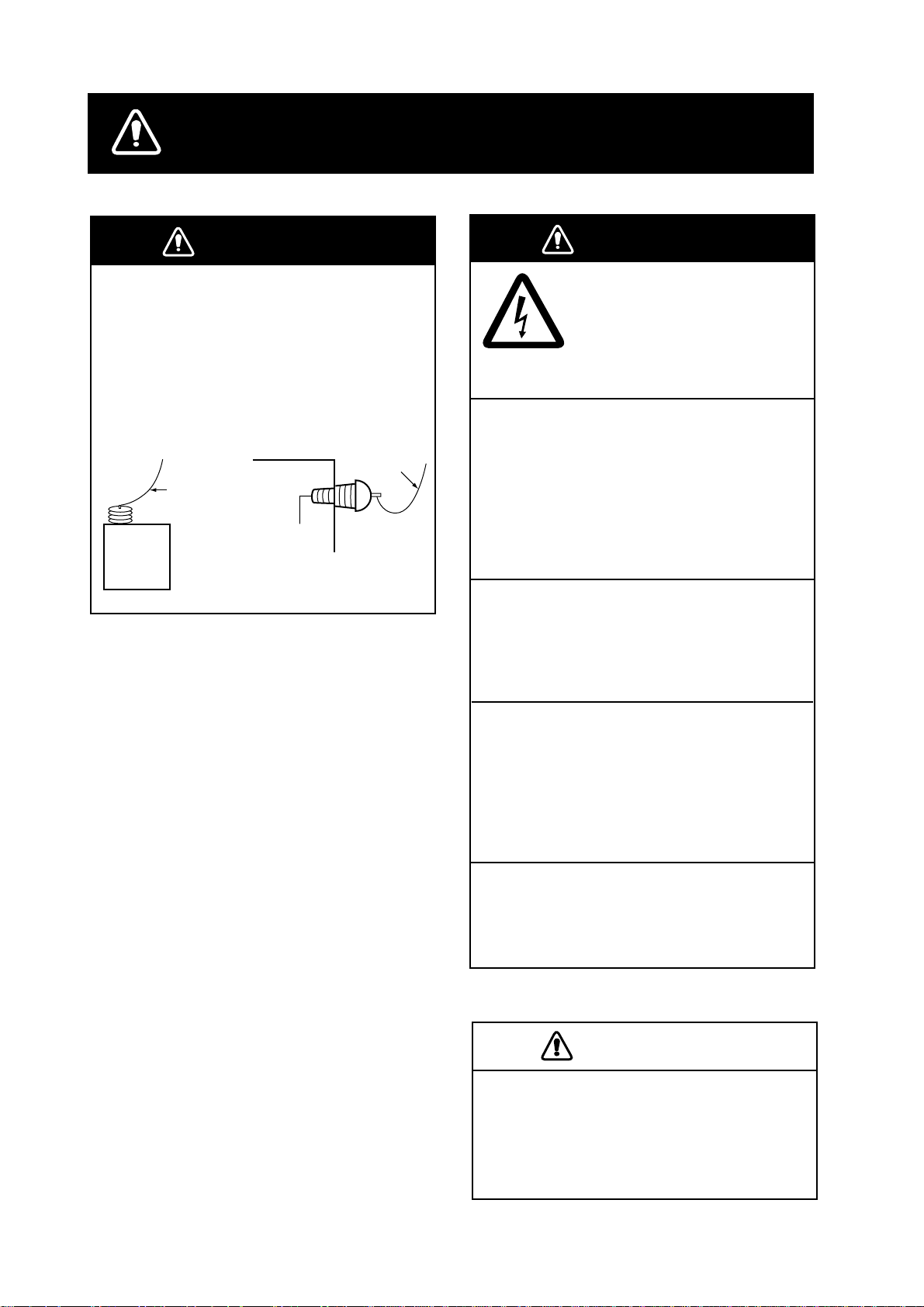
DANGER
Never touch the SSB antenna, antenna
coupler or lead-in insulator when the
SSB radiotelephone is transmitting.
High voltage which will cause death or
serious injury is present at the locations
shown in the illustration below when the
SSB radiotelephone is transmitting.
Antenna
Indoor
Antenna Wire
(High Voltage)
Antenna
Coupler
Wire
Lead-in
Insulator
(High
Voltage)
WARNING
ELECTRICAL SHOCK HAZARD
Do not open the equipment.
Only qualified personnel
should work inside the
equipment.
Immediately turn off the power at the
switchboard if water leaks into the
equipment or something is dropped in
the equipment.
Continued use of the equipment can cause
fire or electrical shock. Contact a FURUNO
agent for service.
Do not disassemble or modify the
equipment.
Fire, electrical shock or serious injury can
result.
Immediately turn off the power at the
switchboard if the equipment is emitting
smoke or fire.
Continued use of the equipment can cause
fire or electrical shock. Contact a FURUNO
agent for service.
Do not operate the equipment with wet
hands.
Electrical shock can result.
CAUTION
Use the proper fuse.
Use of the wrong fuse can cause serious
damage to the equipment and void the
warranty.
ii
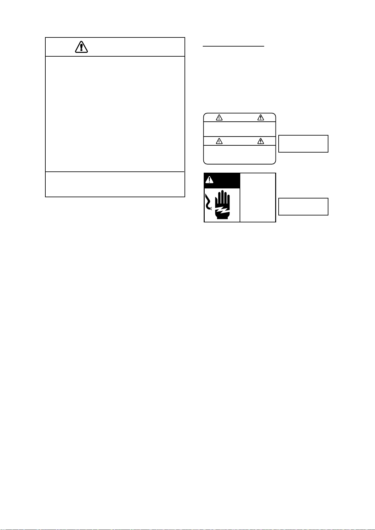
CAUTION
Do not operate the [DISTRESS] button
except in case of a life-endangering
situation on your vessel.
If the distress alert is accidentally
transmitted, contact the nearest coast
station and inform them of the accidental
transmission as follows:
a) Ship's name
b) Ship's call sign and DSC number
c) Position at time of transmission
d) Time of transmission
WARNING LABEL
A warning label is attached to the
transceiver unit and a danger label is
attached to the antenna coupler.
Do not remove the labels.
If a label is missing or illegible,
contact a FURUNO agent or dealer
about replacement.
WARNING
To avoid electrical shock, do not
remove cover. No user-serviceable
parts inside.
Name: Warning Label (1)
Type: 86-003-1011-1
Code No.: 100-236-231
TRANSCEIVER
UNIT
This equipment is intended for maritime
use. Do not use it in other applications.
DANGER
Hazardous voltage.
,
Can shock
burn
or cause death.
Do not touch antenna
,
wire
insulator and
terminal.
Name: Danger Label
,
Type:
05-062-0213-0
Code No.: 100-199-230
ANTENNA
COUPLER
iii

TABLE OF CONTENTS
TABLE OF CONTENTS .......................................................................................iv
FOREWORD.........................................................................................................ix
SYSTEM CONFIGURATION................................................................................xi
SPECIFICATIONS...........................................................................................SP-1
1
OPERATIONAL OVERVIEW.........................................................................1-1
1.1 Controls ....................................................................................................................... 1-1
1.2 Turning the Power On/Off ............................................................................................ 1-2
1.3 Panel Dimmer, LCD Contrast....................................................................................... 1-2
1.4 Indications ................................................................................................................... 1-3
1.4.1 DSC standby screen......................................................................................... 1-3
1.4.2 Radiotelephone screen ..................................................................................... 1-3
1.5 Loudspeaker................................................................................................................ 1-4
1.6 Scanning Routine DSC Frequencies ......................................................................... 1-4
1.7 Automatic Acknowledge On/Off.................................................................................... 1-4
1.8 Manual Entry of Position and Time............................................................................... 1-5
1.9 System Characteristics ................................................................................................ 1-7
1.9.1 Equipment priority............................................................................................. 1-7
1.9.2 Controls become inoperative ............................................................................ 1-7
1.9.3 Controls become operative............................................................................... 1-7
1.9.4 Automatic setting of working frequency............................................................. 1-7
1.10 Power Supply Unit (option) ........................................................................................ 1-8
2 SSB RADIOTELEPHONE .............................................................................2-1
2.1 Transmitting................................................................................................................. 2-1
2.1.1 Choosing class of emission .............................................................................. 2-1
2.1.2 Choosing channel, frequency............................................................................ 2-2
2.1.3 Tuning............................................................................................................... 2-3
2.1.4 Using the handset............................................................................................. 2-4
2.1.5 Monitoring transceiver output power ................................................................. 2-4
2.1.6 Reducing transmitter power .............................................................................. 2-5
2.1.7 Displaying IA, IC, VC or RF .............................................................................. 2-5
2.2 Receiving..................................................................................................................... 2-6
2.2.1 RF gain (sensitivity) adjustment........................................................................ 2-6
2.2.2 S-meter............................................................................................................. 2-6
2.2.3 Monitoring traffic on intended transmit frequency.............................................. 2-6
2.2.4 Receiving AM broadcasting stations ................................................................. 2-6
2.2.5 Squelch control, squelch frequency .................................................................. 2-7
2.2.6 Noise blanker.................................................................................................... 2-7
2.3 Intercom....................................................................................................................... 2-8
2.4 Telex Communications................................................................................................. 2-8
2.5 When Automatic Tuning Fails ...................................................................................... 2-9
iv

2.6 User Channels ...........................................................................................................2-10
2.6.1 Registering user channels...............................................................................2-10
2.6.2 Deleting user channels....................................................................................2-12
2.7 FAX Enable/Disable ...................................................................................................2-12
3 DSC OVERVIEW ...........................................................................................3-1
3.1 What is DSC?...............................................................................................................3-1
3.2 DSC Call ......................................................................................................................3-1
3.2.1 Distress alert call and reply ...............................................................................3-3
3.2.2 Individual call ....................................................................................................3-4
3.3 Audio Alarms ................................................................................................................3-4
3.4 Interpreting Call Displays..............................................................................................3-5
3.4.1 Receive calls.....................................................................................................3-5
3.4.2 Send calls .........................................................................................................3-7
4 DISTRESS OPERATIONS.............................................................................4-1
4.1 Sending Distress Alert ..................................................................................................4-1
4.1.1 Sending distress alert by DISTRESS button, nature of distress not specified....4-1
4.1.2 Sending distress alert by DISTRESS button, nature of distress specified..........4-3
4.2 Receiving a Distress Alert.............................................................................................4-6
4.2.1 Distress alert received on MF band ...................................................................4-7
4.2.2 Distress alert received on HF band ...................................................................4-9
4.3 Sending Distress Relay on Behalf of a Ship in Distress..............................................4-13
4.3.1 Sending distress relay to coast station ............................................................4-13
4.3.2 Sending distress relay to all ships ...................................................................4-16
4.4 Receiving Distress Relay All Ships .............................................................................4-19
4.5 Receiving Distress Relay from Coast Station..............................................................4-19
5 CALLING, RECEIVING..................................................................................5-1
5.1 All Ships Call ................................................................................................................5-1
5.1.1 Sending an all ships call....................................................................................5-1
5.1.2 Receiving an all ships call .................................................................................5-3
5.2 Individual Call...............................................................................................................5-4
5.2.1 Sending an individual call..................................................................................5-4
5.2.2 Receiving an individual call .............................................................................5-10
5.3 Group Call..................................................................................................................5-15
5.3.1 Sending a group call .......................................................................................5-15
5.3.2 Receiving a group call.....................................................................................5-18
5.4 Geographical Area Call ..............................................................................................5-19
5.4.1 Sending a geographical area call ....................................................................5-19
5.4.2 Receiving a geographical area call..................................................................5-22
5.5 Neutral Craft Call........................................................................................................5-23
5.5.1 Sending a neutral craft call.............................................................................. 5-23
5.5.2 Receiving a neutral craft call ...........................................................................5-25
5.6 Medical Transport Call................................................................................................5-26
5.6.1 Sending a medical transport call .....................................................................5-26
5.6.2 Receiving a medical transport call...................................................................5-27
v

5.7 Polling Call................................................................................................................. 5-28
5.7.1 Sending a polling call...................................................................................... 5-28
5.7.2 Receiving a polling call ................................................................................... 5-31
5.8 Position Call...............................................................................................................5-33
5.8.1 Position call: requesting other ship’s position.................................................. 5-34
5.8.2 Position call: other ship requests your position................................................ 5-36
5.9 PSTN Call.................................................................................................................. 5-38
5.9.1 Sending a PSTN call, receiving acknowledge back (ACK BQ)............................ 5-38
5.9.2 Receiving a PSTN call, sending acknowledge back (ACK BQ) ....................... 5-42
5.9.3 PSTN call disconnection, receiving charge information (ship disconnects line)5-43
5.9.4 PSTN call disconnection, receiving charge information (coast station
disconnects line)...................................................................................................... 5-44
5.10 Log File.................................................................................................................... 5-45
5.10.1 Opening a log file.......................................................................................... 5-45
5.11 Erasing Message Files............................................................................................. 5-46
6 PREPARING TX CALLS ...............................................................................6-1
6.1 Preparing Individual Calls ............................................................................................ 6-1
6.2 Preparing Group Calls ................................................................................................. 6-4
6.3 Preparing Geographical Area Calls.............................................................................. 6-5
6.4 Preparing PSTN Calls.................................................................................................. 6-7
6.5 Preparing Test Calls..................................................................................................... 6-8
6.6 Sending Prepared Calls ............................................................................................... 6-9
6.7 Deleting Send Message Files .................................................................................... 6-10
6.8 Printing List of Send Message Files ........................................................................... 6-10
7 DSC/WATCH RECEIVER SETUP .................................................................7-1
7.1 Setting Alarms..............................................................................................................7-1
7.2 Auto Ack Menu............................................................................................................. 7-2
7.3 Printing Messages ....................................................................................................... 7-3
7.4 Setting Scan Frequencies............................................................................................ 7-4
7.4.1 Distress frequencies ......................................................................................... 7-4
7.4.2 Routine frequencies.......................................................................................... 7-5
7.5 Adjusting Volume ......................................................................................................... 7-6
8 NBDP SYSTEM OVERVIEW.........................................................................8-1
8.1 Turning on the NBDP System ...................................................................................... 8-1
8.2 Description of Equipment............................................................................................. 8-2
8.2.1 Terminal unit ..................................................................................................... 8-2
8.2.2 Keyboard.......................................................................................................... 8-3
8.3 Function Keys, Menu Operation................................................................................... 8-4
8.3.1 Menu conventions............................................................................................. 8-4
8.3.2 Menu overview ................................................................................................. 8-4
8.3.3 Function key description ................................................................................... 8-5
vi

9 NBDP PREPARATIONS................................................................................9-1
9.1 Registering Answerback Code & ID Codes...................................................................9-1
9.1.1 Registering answerback code ...........................................................................9-1
9.1.2 Registering ID codes.........................................................................................9-2
9.2 Station List....................................................................................................................9-3
9.2.1 Registering stations...........................................................................................9-3
9.2.2 Editing/Deleting stations....................................................................................9-4
9.3 Timer Programming......................................................................................................9-5
9.3.1 Registering timer programs...............................................................................9-5
9.3.2 Editing/Deleting timer programs ........................................................................9-6
9.4 User Channels .............................................................................................................9-6
9.4.1 Registering user channels.................................................................................9-6
9.4.2 Editing/Deleting user channels..........................................................................9-7
9.5 Scan Channel Groups ..................................................................................................9-7
9.5.1 Registering scan channel groups ......................................................................9-7
9.5.2 Editing/Deleting scan channel groups ...............................................................9-8
10 NBDP FILE OPERATIONS..........................................................................10-1
10.1 Opening and Closing Files .......................................................................................10-1
10.2 Creating Files...........................................................................................................10-1
10.3 Saving a File ............................................................................................................10-2
10.3.1 Formatting floppy disks .................................................................................10-2
10.3.2 Saving a file ..................................................................................................10-2
10.4 Editing Files..............................................................................................................10-3
10.4.1 Cutting and pasting text.................................................................................10-3
10.4.2 Copying and pasting text...............................................................................10-4
10.4.3 Select all .......................................................................................................10-4
10.4.4 Searching text...............................................................................................10-4
10.4.5 Replacing text ...............................................................................................10-5
10.4.6 Goto line........................................................................................................10-5
10.4.7 Goto top, Goto bottom...................................................................................10-6
10.5 Opening Files...........................................................................................................10-6
10.5.1 Opening a file................................................................................................10-6
10.5.2 Switching between files.................................................................................10-6
10.6 Renaming Files ........................................................................................................10-7
10.7 Saving a File Under a New Name ............................................................................10-7
10.8 Deleting Files ...........................................................................................................10-7
10.9 Real Time Printing....................................................................................................10-7
10.10 Printing Files ..........................................................................................................10-8
11 NBDP TRANSMITTING, RECEIVING .........................................................11-1
11.1 Manual Calling.......................................................................................................... 11-1
11.2 ARQ Mode Operation ...............................................................................................11-3
11.3 FEC Mode Operation................................................................................................ 11-5
11.4 Choosing Receive Mode........................................................................................... 11-5
11.5 Communication Example.......................................................................................... 11-6
vii

11.6 Timer Operation ....................................................................................................... 11-8
11.6.1 Enabling timer operation ............................................................................... 11-8
11.6.2 Stopping timer operation ............................................................................... 11-9
11.7 Scanning.................................................................................................................. 11- 9
11.8 Communication Buffer.............................................................................................11-10
11.9 Preparing Macrofiles for Automatic Telex.................................................................11-10
11.9.1 Automatic telex overview..............................................................................11-10
11.9.2 Preparations.................................................................................................11-11
11.9.3 Commands ..................................................................................................11-12
11.9.4 Store-and-forward method............................................................................11-13
11.9.5 DIRTLX macrofile.........................................................................................11-15
11.10 Automatic Telex using Macrofile ............................................................................11-17
12 MAINTENANCE & TROUBLESHOOTING .................................................12-1
12.1 Daily Test ................................................................................................................. 12-1
12.2 Radiotelephone Test ................................................................................................ 12-2
12.3 Antenna Coupler Test............................................................................................... 12-2
12.4 Maintenance ............................................................................................................ 12-3
12.5 Replacement of Fuses ............................................................................................. 12-4
12.6 Simple Troubleshooting............................................................................................ 12-5
12.7 Error Messages ....................................................................................................... 12-6
12.8 Test Call ................................................................................................................... 12-7
12.9 NBDP Terminal Unit Maintenance............................................................................ 12-9
12.9.1 Cleaning the equipment................................................................................ 12-9
12.9.2 Connectors and earth connection ................................................................. 12-9
12.9.3 Floppy disk drive........................................................................................... 12-9
12.9.4 Diagnostics................................................................................................. 12-10
APPENDIX.......................................................................................................AP-1
Menu Tree ...................................................................................................................... AP-1
Frequency Tables ........................................................................................................... AP-4
Telex Abbreviations....................................................................................................... AP-17
Digital Interface (IEC 61162-1)...................................................................................... AP-18
Parts List....................................................................................................................... AP-23
Parts Location............................................................................................................... AP-26
INDEX ............................................................................................................... IN-1
Declaration of conformity
viii

FOREWORD
Thank you for purchasing the FS-1570 (150 W)/ F S-2570 (250 W) SSB Radiotelephone.
We are confident you will discover why FURUNO has become synonymous with quality
and reliability.
Dedicated in the design and manufacture of marine electronics equipment for over half a
century, FURUNO Electric Company has gained an unrivaled reputation as a world leader
in the industry. This is the result of our technical excellence as well as our worldwide
distribution and service network.
Please carefully read and follow the saf et y information and operating and m aintenance
instructions set forth in this manual before attempting to operate the equipm ent and
conduct any maintenance. Your unit will perform to the utmost of its ability only if it is
operated and maintained in accordance with the correct procedures.
Note: The example screens shown in this manual may not match the screens you see on
your display. The screen you see depends on your system configuratio n and equipment
settings.
Features
The FS-1570/FS-2570 is an MF/HF SSB Radiotelephone with a built-in DSC/Watch
Receiver, all contained in a surprisingly compact cabinet. An NBDP (Narrow Band Direct
Printing) Term inal Unit is optionally available.
Data is displayed on a large, easy-to-read backlit LCD. Operation is simplified by the use
of few keys and easy-to-follo w menus.
The built-in DSC/watch receiver produces and r eceives digital selective calls for quick and
efficient establishment of distress, urgency, safety and routine communications with other
ships and coast stations that install any MF/HF DSC facilities.
The main features are
General
•
Fully meets the following regulations: IMO A.694(17), IMO A.804(19), IMO A.806(19),
IMO A.813(19), IMO MSC 68(68), IEC 60945, IEC 61907-3/8/9, IEC-61162-1,
EIV-300/338, ITU-R M.493-10, M.541-8, M.1082-1, EN 300 373, EN 300 338, EN 300
033 and ETS 300 067.
•
One-touch testing facility
•
Automatic entry of position with manual override
•
Optional printer can automatically print out DSC and NBDP received messages and test
results.
ix

DSC/watch receiver
•
Distress, safety and routine calling
•
Scanning of DSC frequencies for distress and general calls on MF/HF
•
File editing capability for readiness in case of emergency
•
PSTN (Public Switched Telephone Network) capability standard
•
Log stores 50 each of latest ordinary, distress and transmitted messages, in separate
memory blocks.
NBDP (with optional NBDP Terminal Unit IB-581/IB-583)
•
Automatic error-free telex communications and distress message in compliance with
GMDSS requirements
•
LCD monitor and keyboard comply with ITU regulations
•
Pop-up menus for user-friendly operation
•
Memory for 100 operator-customized channels
•
Real time message printing with Printer PP-510
Program Number
PC Board Program No. On Display Remarks
MAIN (Transceiver Unit) 0550205101
PANEL 1 (#1 Control Unit) 0550206101
PANEL 2 (#2 Control Unit) 0550206101
MODEM (DSC) 0550207101
NBDP MODEM 0550208101
Terminal Unit IB-581 (optional unit)
PC Board Program No. On Display Remarks
Terminal Unit 0550210122 Ver. 1.22
Terminal Unit IB-583 (optional unit)
Ver. 01 FS-1570T/FS-2570T
Ver. 01 FS-2570C
Ver. 01 Optional unit
Ver. 01
Ver. 01 Optional pcb
PC Board Program No. On Display Remarks
Terminal Unit 0550209122 Ver. 1.22
x
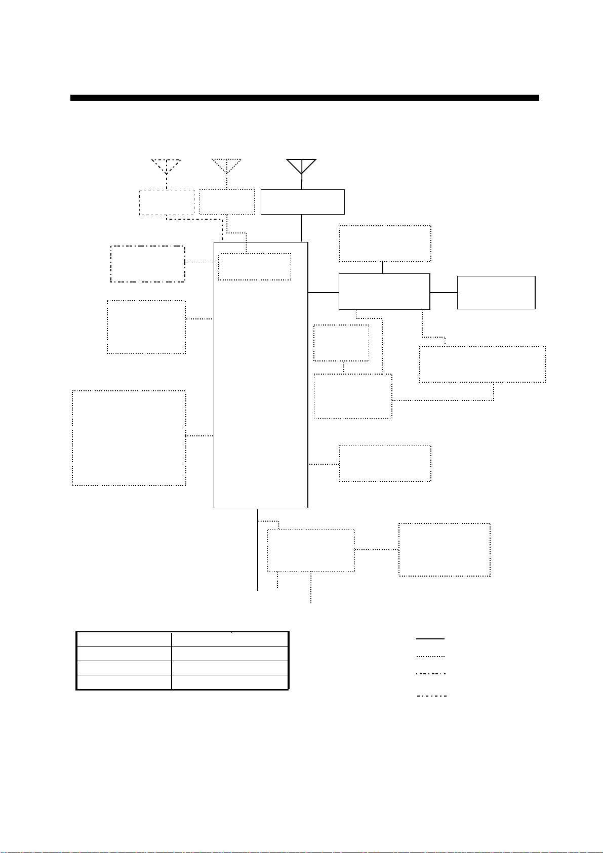
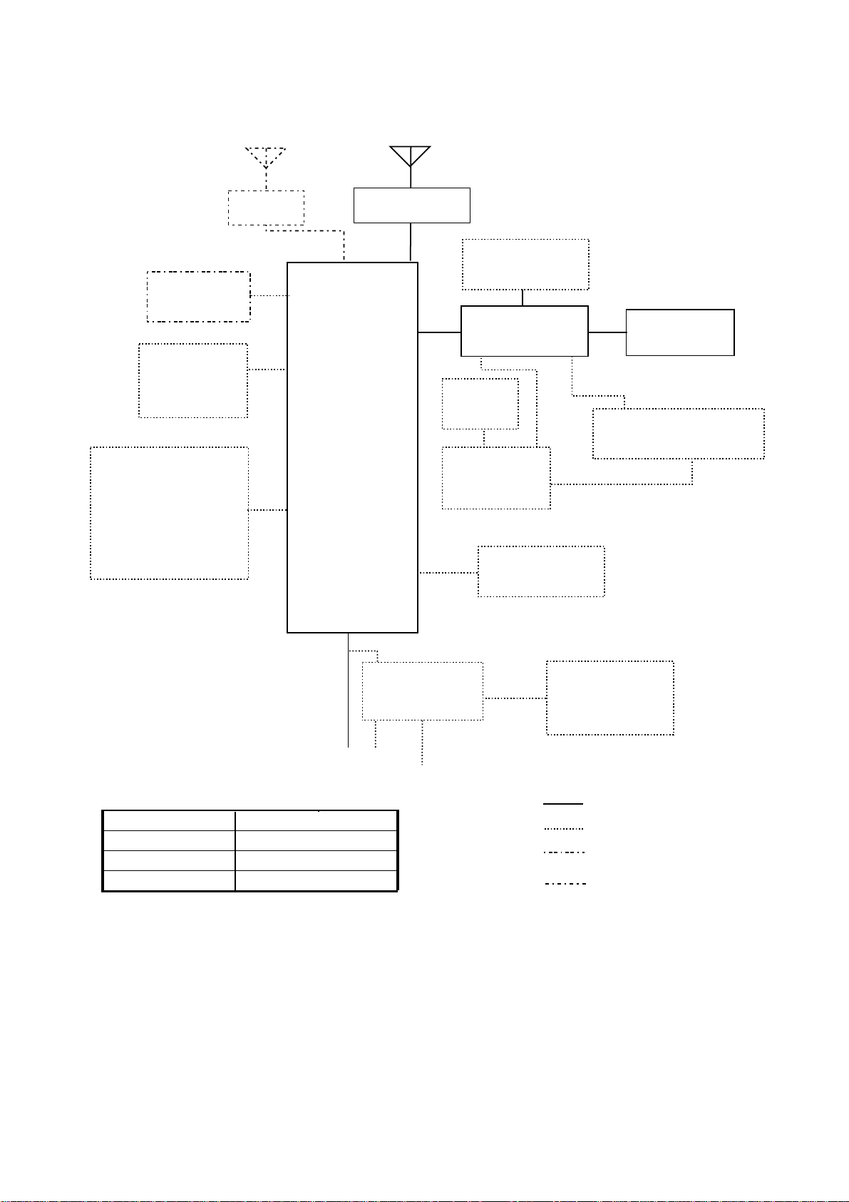
SYSTEM CONFIGURATION
FS-2570 (250 W)
* **
PREAMP
FAX-5
NAVIGATOR
INCOMING
INDICATOR
IC-303-DSC
TELEX DISTRESS
ALERT BUTTON
IC-302-DSC
or
DISTRESS MESSAGE
CONTROLLER
DMC-5
PREAMP
FAX-5
RX BOARD**
CONTROLLER 1
TRANSCEIVER
UNIT
FS-2570T
CONTROLLER 2
Antenna Coupler
AT-1560-25
PRINTER
PP-510
PRINTER
SWITCH BOX
LOUDSPEAKER
SEM-21Q
CONTROL UNIT
FS-2570C
CONTROL UNIT
FS-2570C
HANDSET
HS-2001
NBDP TERMINAL UNIT
IB-581/IB-583
Note: The CONTROL
UNIT connected to
CONTROLLER 1
has priority.
* = For distress watch keeping receiver
** = For DSC general frequency
watch keeping receiver
SHIP'S MAINS
Unit
Preamp Unit
Antenna Coupler
Other Units
Exposed to weather
Exposed to weather
Protected from weather
Category
AC/DC POWER
SUPPLY UNIT
PR-850A
24 VDC
100-115/200-230 V AC
1φ, 50/60 Hz
POWER STATUS
MONITOR
PSM-01
: STANDARD
: OPTION
: EXTERNAL EQUIPMENT
: REQUIRED
(local supply or
option)
xi
FS-1570 (150 W)
*
NAVIGATOR
INCOMING
INDICATOR
IC-303-DSC
TELEX DISTRESS
ALERT BUTTON
IC-302-DSC
or
DISTRESS MESSAGE
CONTROLLER
DMC-5
PREAMP
FAX-5
Antenna Coupler
AT-1560-25
CONTROLLER 1
TRANSCEIVER
UNIT
FS-1570T
CONTROLLER 2
LOUDSPEAKER
SEM-21Q
CONTROL UNIT
FS-2570C
PRINTER
PP-510
PRINTER
SWITCH BOX
CONTROL UNIT
FS-2570C
HANDSET
HS-2001
NBDP TERMINAL UNIT
IB-581/IB-583
Note: The CONTROL
UNIT connected to
CONTROLLER 1
has priority.
* = For distress watch keeping receiver
Unit
Preamp Unit
Antenna Coupler
Other Units
Exposed to weather
Exposed to weather
Protected from weather
Category
AC/DC POWER
SUPPLY UNIT
PR-300
SHIP'S MAINS
24 VDC
100-115/200-230 V AC
1φ, 50/60 Hz
POWER STATUS
MONITOR
PSM-01
: STANDARD
: OPTION
: EXTERNAL EQUIPMENT
: REQUIRED
(local supply or
option)
xii

SPECIFICATIONS OF SSB TRANSCEIVER
FS- 1570/2570
1 MF/HF DIGITAL RADIOTELEPHONE
1.1 GENERAL
1.1.1 Communication System Semi-duplex or simplex
1.1.2 Class of Emission J3E: Telephone
J2B (F1B): DSC or NBDP
H3E: reception only
1.1.3 Frequency Range 100.00 kHz to 29,999.99 kHz
1.1.4 Number of Channel User programmable: 255 TX/RX pairs
All ITU channels incorporated (include DSC/NBDP channels)
2182 kHz (single action)
1.1.5 Display Method Monochrome LCD (120 x 64 dots)
1.1.6 Backlight 8 tones
1.1.7 Contrast 64 steps
1.1.8 Warming up 1 minute approx. (oven 20 minutes approx.)
1.2 TRANSMITTER
1.2.1 Frequency Range 1,606.5 kHz to 27.5 MHz (100 Hz steps)
1.2.2 RF output Power FS-1570: 150 Wpep, FS-2570: 250 Wpep
1.2.3 Frequency Resolution Within ±10 Hz
1.2.4 Modulation AF Response 350 Hz to 2.7 kHz
1.2.5 Modulation System Low power balanced modulation
1.2.6 AF Input -46 dBm/600 ohms (Handset/Microphone)
-10 dBm/600 ohms (Handset HS-2001)
1.2.7 Line in 0 dBm/600 ohms
1.3 RECEIVER
1.3.1 Receiving System Double-conversion superheterodyne
1.3.2 Frequency Range 100 kHz 29,999.9 kHz (10 Hz steps)
1.3.3 Sensitivity Input level at 10 ohms+250 pF (below 4 MHz) and 50 ohms
(above 4MHz) to produce SINAD 20 dB
Frequency Range J3E/H3E
100 kHz to 300 kHz 35 dBµV
300 kHz to 1.6 MHz 25 dBµV
1.6 MHz to 4.0 MHz 13 dBµV
4.0 MHz to 30 MHz 7 dBµV
SP - 1 E5637S01C-M

1.4 Intermediate Frequency 1st: 72,455 kHz, 2nd: 455 kHz
1.5 Selectivity J3E: 2.4kHz at -6dB, H3E: 6kHz at -6dB
J2B (F1B): 300Hz at -6dB
1.6 Inter-modulation Better than 80 dBµV
1.7 Spurious Response Better than 70 dB
1.8 AGC SLOW/FAST/OFF
1.9 BFO Frequency Telex/DSC: 1,700 Hz, Facsimile: 1,900 Hz
1.10 Audio Output Power Internal speaker: 1W/ 8 ohms
External speaker: 4W/ 4 ohms
Handset: 2.5mW/ 150 ohms
Line output: 0 dBm/ 600 ohms
1.11 Standard Features Noise Blanker, Voice-activated squelch, Pre-selector
2 DSC/WATCH KEEPING RECEIVER
2.1 DIGITAL SELECTIVE CALLING
2.1.1 Frequency Shift Space: 1785.0 ± 0.5 Hz, Mark: 1615.0 ± 0.5 Hz
2.1.2 Baud Rate 100 bps ± 30 x 10-6
2.1.3 Protocol Complies with ITU-R Rec.493-10, 541-8, 1082-1
2.1.4 Modulation AFSK
2.1.5 Distress Alarm 3.5 s to 4.5 s self-repetition
2.1.6 Distress Alarm Memory 50 messages
2.2 DSC/WATCH RECEIVER
2.2.1 Frequency Range
MF/HF specification 2187.5/ 8414.5 and 4207.5/ 6312/12577/16804.5 kHz
MF specification 2187.5 kHz
2.2.2 Class of Emission F1B, J2B
2.2.3 Antenna Impedance 50 ohms
2.2.4 Local Oscillator 1st: F+54,455 kHz, 2nd: 54,000 kHz, 3rd: 456.7 kHz
2.2.5 Frequency Stability ±10 Hz
2.2.6 Intermediate Frequency 1st: 54,455 kHz, 2nd: 455 kHz
2.2.7 Selectivity -6 dB: 270 Hz to 300 Hz,
-30 dB: within ± 380 Hz,
-60 dB: within ± 550 Hz
2.2.8 Receiving System Double-conversion superheterodyne
2.2.9 Radiation within 2 mW
2.2.10 RX Error Rate 1 % or less at 1 µV input voltage
2.2.11 Spurious Response 31.6 mV non-modulated at 10µV input voltage,
SP - 2 E5637S01C-M

at error rate within 1%
2.2.12 Scanning Reception max. 6 frequencies within 2 s (MF/ HF)
2.2.13 Diagnosis Transmit high frequency signal of DSC
2.3 GENERAL WATCH KEEPING RECEIVER (FS-2570 ONLY, OPTION)
2.3.1 Frequency Range 1,606.5 kHz to 27.5 MHz
2.3.2 Class of Emission J2B, F1B
2.3.3 Antenna Impedance 50 ohms
2.3.4 Local Oscillator 1st: F+54,455 kHz, 2nd: 54,000 kHz, 3rd: 456.7 kHz
2.3.5 Frequency Stability within ±10 Hz
2.3.6 Intermediate Frequency 1st: 54,455 kHz, 2nd: 455 kHz
2.3.7 Selectivity -6 dB: 270 Hz t o 300 Hz,
-30 dB: within ± 380 Hz,
-60 dB: within ±550 Hz
2.3.8 Receiving System Double-conversion superheterodyne
2.3.9 Radiation within 2 mW
2.3.10 RX Error Rate 1 % or less at 1 µV input voltage
2.3.11 Spurious Response 31.6 mV non-modulated at 10µV input voltage,
at error rate within 1%
2.3.12 Scanning Reception max. 6 frequencies within 2 s (MF/ HF)
2.3.13 Diagnosis Transmit high frequency signal of DSC
3 NBDP FUNCTION (OPTION)
GENERAL
3.1
3.1.1 Communication Mode ARQ, FEC, DIRC (FSK)
3.1.2 Protocol ITU-R M625-3, M476-5, M490, M491-1, M492-6
ID code 4, 5, 9 column
Line cord 4B/3Y (I nt l.)
Modulation AFSK
Tone frequency 1615/1785Hz ± 0. 5 Hz (mark/space)
Tracking range ±80 Hz
3.1.3 Applications
Auto-reception Setting timer and frequency (max. 10 settings available)
Frequency scanning 10 group max., 20 station as each group
User-channels 100 channels max.
4 TERMINAL UNIT (IB-583)
4.1 Display 10.4-inch color TFT 640 x 480 dots
SP - 3
E5637S01C-M

4.2 CPU HD6417615 (15.5 MHz)
4.3 Memory Flash ROM: 1 MB, S-RAM: 256 KB
4.4 FD Drive 720 KB/1.44MB 3.5”
4.5 Keyboard 82 keys, IBM PS/2
4.6 Other functions Text editor, FD control, Printer, NAV-data reception/display,
Remote control for Transceiver, Diagnosis
5 ANTENNA COUPLER
5.1 Tuning System CPU controlled fully automatic tuning system
5.2 Frequency Range 1.6 MHz to 27.5Hz
5.3 Input Impedance 50 ohms
5.4 Antenna 7m to 30m wire or whip antenna
5.5 Power Capability 150 W (FS-1570), 250 W (FS-2570)
5.6 VSWR 1.5 max
5.7 Tuning Speed Within 15 s
5.8 Dummy Load FS-1570: 10 ohms + 250 pF/200W mounted in coupler
FS-2570: 10 ohms + 250 pF/100W mounted in coupler
6 INTERFACE
6.1 Input data sentences IEC 61162-1 (NMEA 0183-3)
Ship’s Position (L/L) GGA>RMC>GLL
Time ZDA
7 POWER SUPPLY
7.1 Transceiver Unit/Control Unit
FS-1570 24 VDC: 0.8 A, max. 20 A (TX)
FS-2570 24 VDC: 1.5 A, max. 35 A (TX)
7.2 AC/DC Power Supply Unit (option) 100/110/115/220/230VAC, 1 phase, 50/60 Hz
8 ENVIRONMENTAL CONDITIO N
8.1 Ambient Temperature -15°C to +55°C
8.2 Relative Humidity 93 or less at 40°C
8.3 Water proofing Control Unit (Panel): IPX2
(IEC 60529) Transceiver Unit: IPX0
Antenna Coupler: IPX5
8.4 Vibration IEC 60945
SP - 4 E5637S01C-M

9 COATING COLOR
9.1 Control Unit Chassis: 2.5GY5/1.5, Panel: N3.0
9.2 Transceiver Unit 2.5GY5/1.5
9.3 Antenna Coupler N9.5 (white)
SP - 5 E5637S01C-M

This page is intentionally left blank .
1 OPERATIONAL OVERVIEW
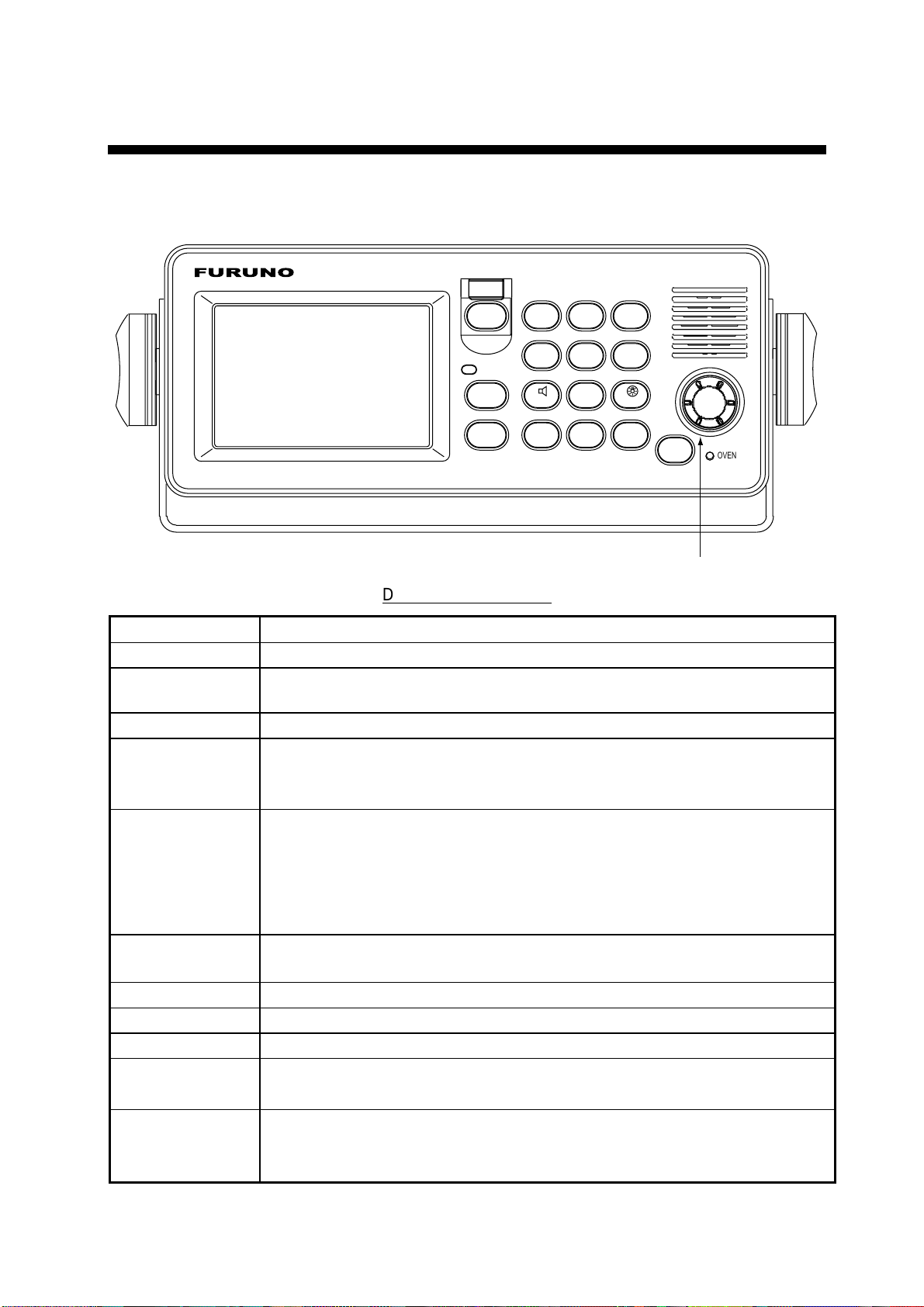
1.1 Controls
FURUNO
RT
DSC
DISTRESS
1
2182
2
ABC
3
TEST
DEF
ALARM
CANCEL
CALL
IntCom
4
7
*
GHI
PQRS
FILE
CURSOR
ACK/SQ
5
ABC
PRINT
8
TUV
LOG
0
TUNE
SCAN
6
MNO
9
WXYZ
SETUP
#
PUSH TO ENTER
POWER
OVEN
ENTER knob
Description of controls
Control Function
POWER switch Turns the power on/off.
DISTRESS
button
Press and hold down the button more than three seconds to transmit the
distress alert.
CALL key Transmits calls.
ENTER knob
Radiotelephone: Rotate to change TX/RX channel, sensitivity, audio
volume, etc.; push to register selection.
DSC: Rotate to choose menu items; push to register selection.
CANCEL key
• Cancels wrong data.
• Restores previous menu.
• Silences audio alarm.
• Cancels transmission, printing.
• Erases error message.
1/ RT/2182 key
Switches to the radiotelephone screen. Press and hold down more than
two seconds to get 2182.0 kHz/J3E automatically.
2/DSC key Composes DSC TX message.
3/TEST key Executes daily test.
4/IntCom key Turns on/off the intercom with other Control Unit FS-2570C.
5/ ACK/SQ key
DSC: Switches automatic and manual acknowledge alternately.
Radiotelephone: Turns squelch on and off.
6/SCAN key
• Displays DSC standby screen.
• Starts/stops scanning of DSC routine frequencies, on the DSC standby
screen.
1-1
1 OPERATIONAL OVERVIEW
7/
key
• Turns loudspeaker on/off.
(Note that this key does not silence the distress or urgency alarm.)
8/PRINT key Prints communications log files, current screen (except DSC standby
screen and radiotelephone screen) and test results.
key
9/
FILE/CURSOR
key
Adjusts panel dimmer and LCD contrast.
• Opens the send message file list from the DSC standby screen, to send
stored message.
• Shifts cursor.
LOG/TUNE key
• Tunes antenna in radiotelephone operation.
• Displays message logs, in DSC operation.
#/SETUP key Opens the Setup menu.
ALARM lamp
• Flashes in red for distress and urgency calls.
• Flashes in green (more rapidly) for business, safety and routine calls.
OVEN lamp Lights (in green) when mains switchboard is on.
1.2 Tu rn ing the Power On/Off
Press the [POWER] switch at the right-hand side of the control unit to power the system.
Press it again to turn the system off. In the dual control unit system, the control unit
connected to the CONTROLLER 1 port on the tr ansceiver unit has priority and it controls
the power for both the No.1 and No. 2 control units. The power switch of the No. 2 cont rol
unit powers on/off the No. 2 control unit only.
Note: Turn on ship’s mains five minutes before turning on this equipment.
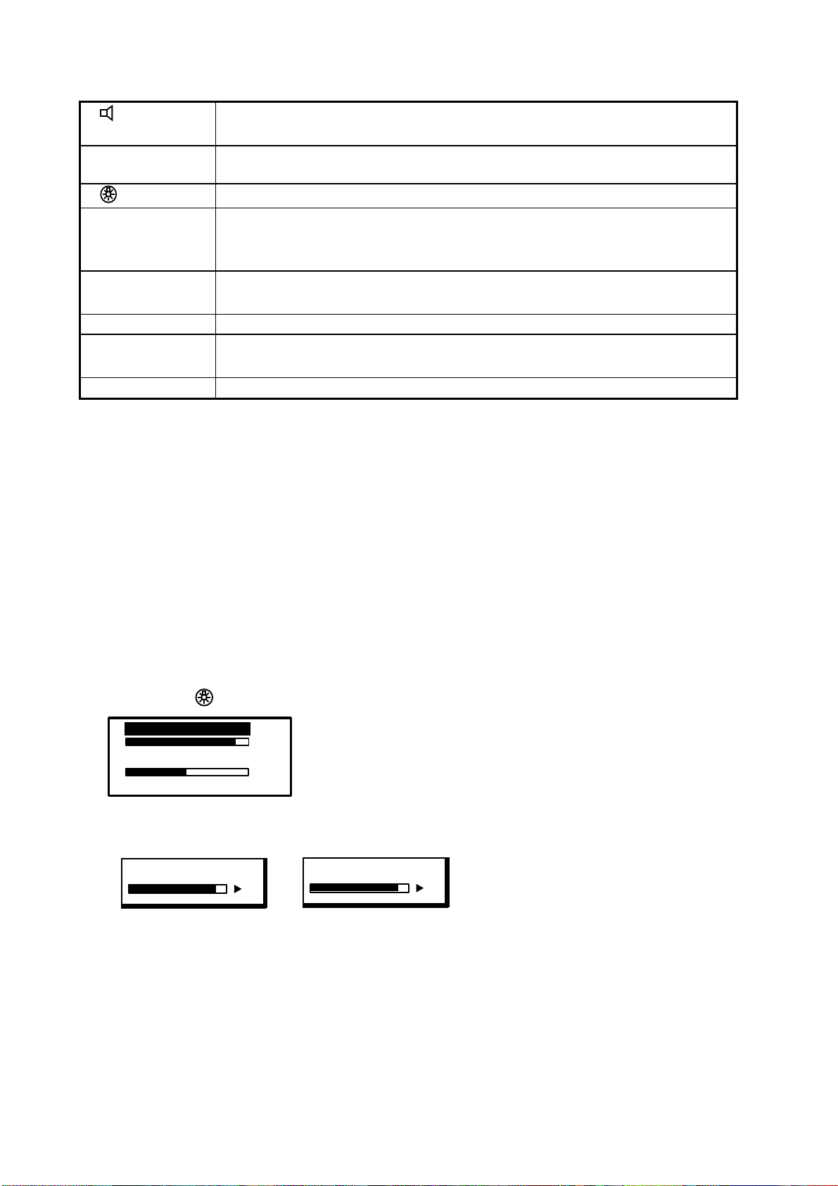
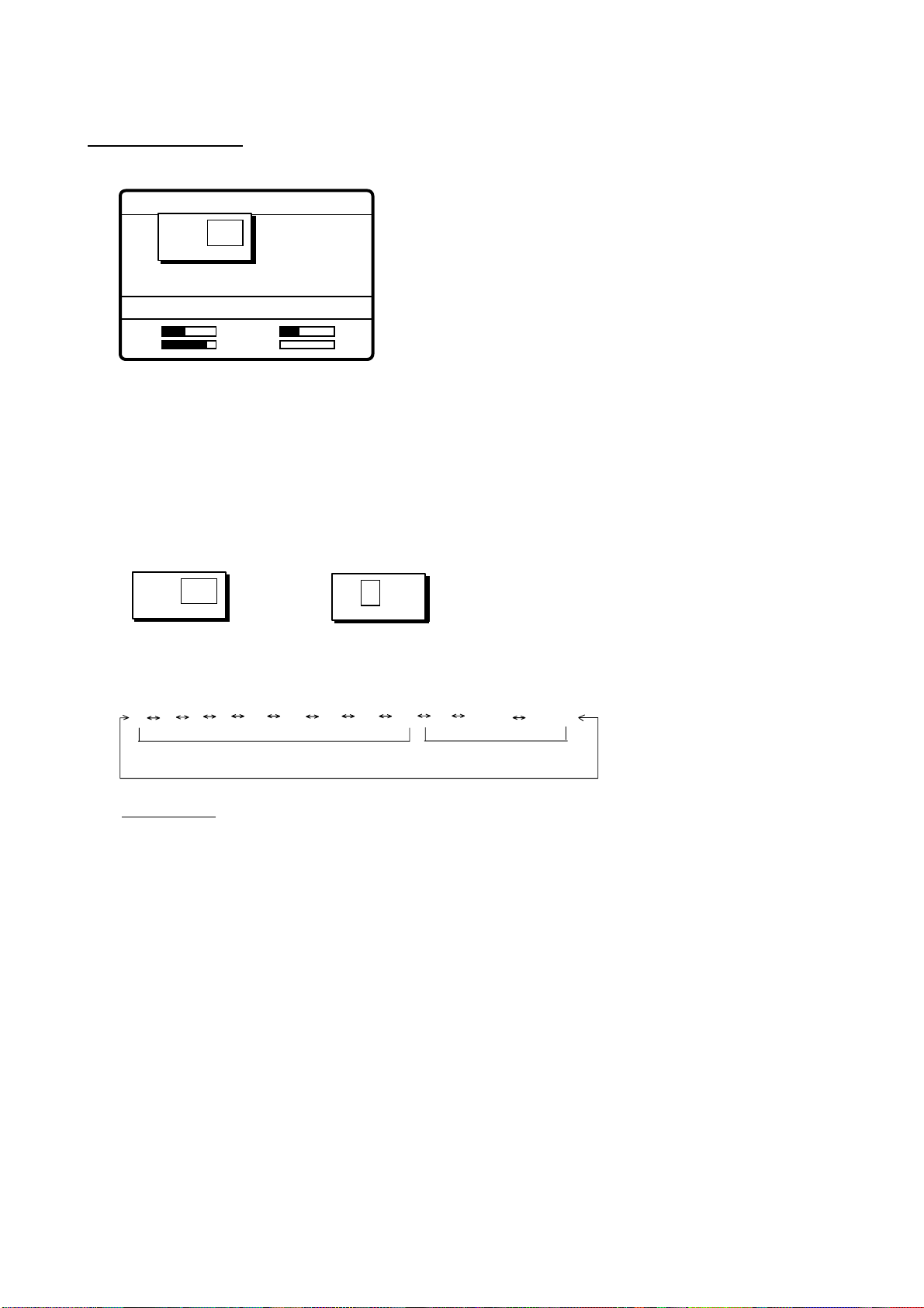
1.3 Panel Dimmer, LCD Contrast
1. Press the [9/
DIMMER (1~8)
CONTRAST (40~63)
2. Rotate the [ E NTER] knob to choose DIMMER or CONTRAST, whichever you want to
adjust, and then push the [ENTER] knob.
DIMMER (1-8)
] key to show the dimmer/contrast adjustment window.
6
45
EXIT:[ENT]
6
CONTRAST (40-63)
55
Dimmer adjustment window Contrast adjustment window
3. Rotate t he [ENTER] knob to adjust and then push the [ENTER] knob.
4. To quit, rotate the [ENTER] knob to choose “EXIT: [ENT]” and then push the [ENTER]
knob.
Note: The DIMMER is automatically set to 5 and the CONTRAST to 45 whenever the
power is turned on.
1-2
1 OPERATIONAL OVERVIEW
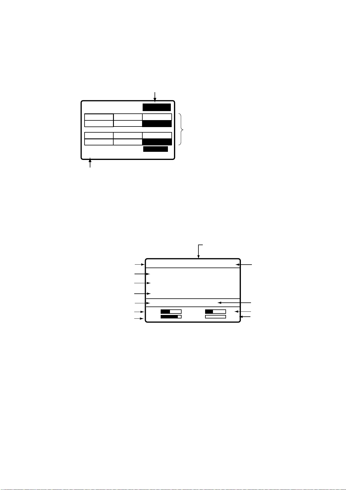
1.4 Indications
1.4.1 DSC standby screen
The DSC standby screen may be displayed by pressing the [6/SCAN] key.
Acknowledge status
(AUTO ACK or MANUAL ACK)
WATCH KEEPING
DISTRESS
2187.5
16804.5 12577.0
ROUTINE
2177.0
16903.0 12657.0
35°00.000N MANUAL
135°00.000E 23:59
Position and time. "MANUAL" shown
when these are input manually.
4207.5
4219.5
AUTO ACK
6312.0
8414.5
6331.0
8436.5
Distress and routine frequencies
scanned in clockwise direction,
and frequency currently being
scanned is highlighted.
One cycle is completed
in less than two seconds.
For how to choose scan
frequencies, see paragraph 1.6.
DSC standby screen
1.4.2 Radiotelephone screen
Press the [1/ RT/2182] key to show the radiotelephone screen. This is where you set up
the radiotelephone.
Communications Mode
(Duplex or Simplex, display only)
Class of Emission (SSB, TLX, AM)
Channel
TX Frequency
RX Frequency
AGC, Squelch
Sensitivity
Volume
MODE: SSB SIMP HIGH
CH: 200
TX: 2182.0 KHZ
RX: 2182.00 KHZ
AGC : FAST SQ NB
SEN
VOL
S
IA 0.0A
Output Power
(HIGH, MID or
LOW)
Noise Blanker
S-meter
Antenna Current (IA)
(or IC, VC, RF)
Radiotelephone screen
Note:
“TX” is circumscribed with a rectangle when transmitting.
1-3

1 OPERATIONAL OVERVIEW
1.5 Loudspeaker
1.
Press the [7/ ] key to alternately disable or enable the loudspeaker and the alarm
generated for routine messages. SOUND: ON or SOUND: OFF appears with each
press.
2. To adjust loudspeaker volume do the following:
a) Press the [1/RT 2182] key to show the radiotelephone screen.
b) Rotate the [ENTER] k nob t o choose VO L at the bottom of the screen and t hen push the
[ENTER] knob.
c) Rotate the [ENTER] knob to adjust volume and then push the [ENTER] knob.
VOL
"OFF" shown when loudspeaker is off.
1.6 Scanning Routine DSC Frequencies
You can scan frequencies when using the DSC mode. For how to set frequencies, see
paragraph 7.4. Radiotelephone and telex are inoperative while scanning. However, in
case of the FS-2570, those modes may be used during scanning when the optional
internal watch keeping receiver is installed.
1. Press the [6/ S CAN] key to show the DSC standby screen.
2. Press the [6/ S CAN] key to st art/stop scanning.
1.7 Automatic Acknowledge On/Off
The automatic acknowledge feature of the DSC/watch receiver automatically transmits the
acknowledge back (ACK BQ) signal to the sending station when an individual, position or
polling call is received. (For position and polling calls, respective item on the AUTO ACK
menu must be t urned on to enable automatic acknowledge.) Automat ic acknowledge can
be turned on or off at the DSC standby screen by the [5/ ACK/SQ ] key. The message
ACK: AUTO or ACK: MANUAL appears at the bottom of the DSC standby screen with
each press of the key.
Note 1:
Note 2:
To give priority to own ship’s communications while own ship is communicating,
show ACK: MANUAL by the above procedure.
Automatic acknowledge is not possible under the following conditions:
Priority:
Com Type: Morse, Fax, Data, No Info
Com Freq: No Info
Off Hook
Distress, Urgency or Safety
1-4
1 OPERATIONAL OVERVIEW
1.8 Manual Entry of Position and Time
If there is no EPFS (Electronic Position-Fixing System) connected to this equipment or the
EPFS connected is not working (EPFS error indication appears), manually enter position
and time as follows:
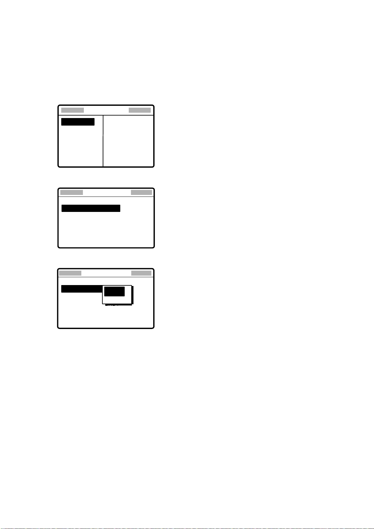
1. At the DSC standby screen, press the [#/SETUP] key to display the Setup menu.
Setup menu
****
ALARM
AUTO ACK
ERASE
MESSAGE
POSITION
PRINT OUT
****
SCAN FREQ
VOLUME
TEST
SYSTEM
2. Rotate the [ENTER] knob to choose POSITION and then push the [ENTER] knob.
** Position setup
INPUT TYPE: AUTO
LAT : 34
LON : 135
TIME: 09: 00 UTC
°
41 NORTH
°
30 EAST
**
3. Push the [E NTER] knob to open the INPUT TYPE menu.
** Position setup
INPUT TYPE: AUTO
LAT : 34
LON : 135
TIME: 09: 00 UTC
AUTO
°
41 NORTH
N
MANUAL
°
30 EAST
**
Note 1:
If, when INPUT TYPE is AUTO, input from the navigator is interrupted, the
message “EPFS error!” appears. If this occurs, check the navigator.
Note 2:
When INPUT TYPE is MANUAL, the message “Warning: Update position”
appears at set intervals (update interval selected with POSITION OLDER on
the Alarm menu) to ask you to update position.
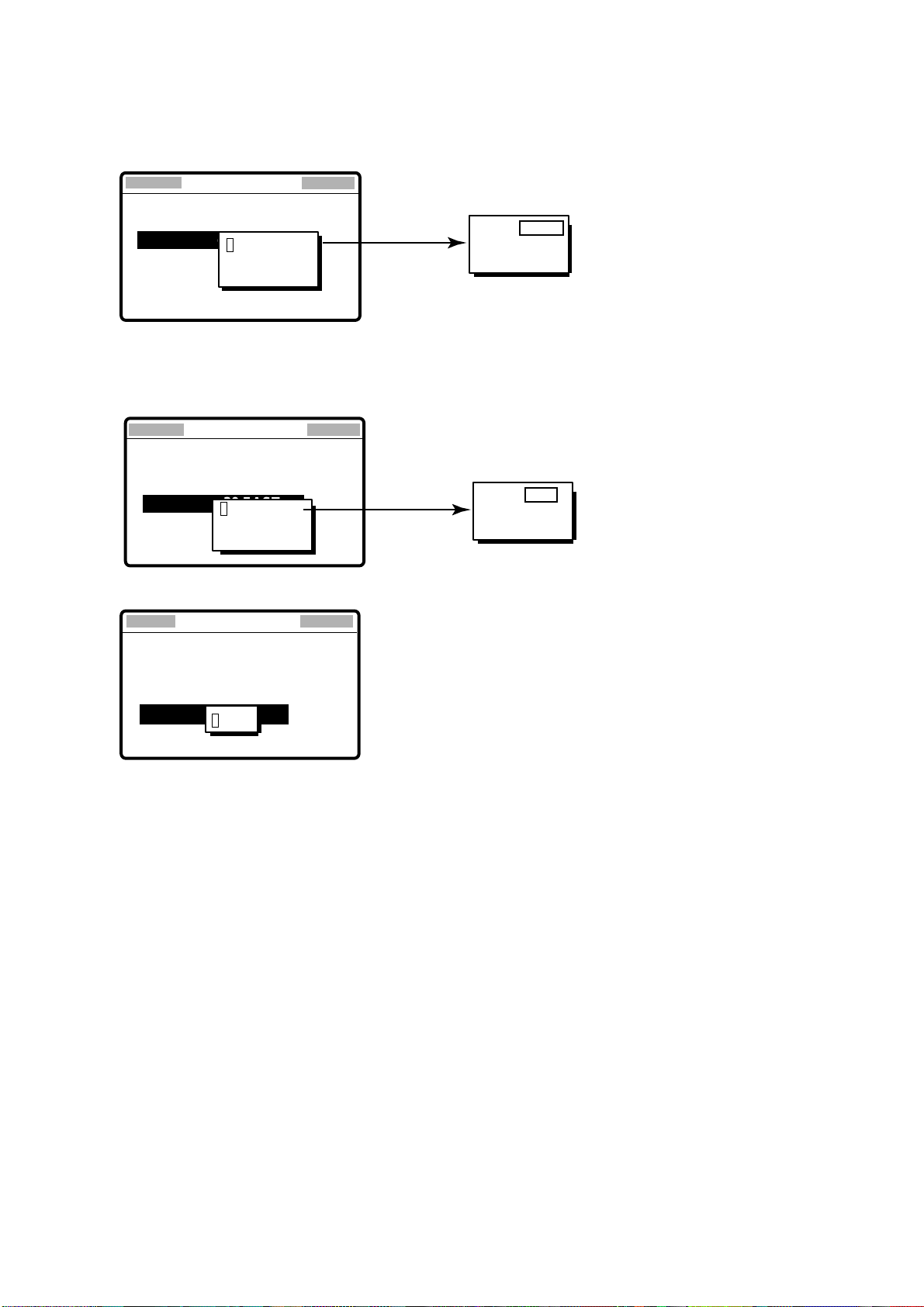
4. Rotate the [ENTER] knob to choose MANUAL and then push the [ENTER] knob.
1-5
1 OPERATIONAL OVERVIEW
5. Push the [ E NTER] knob to open the latitude input window. Use the numeric keys to
enter latitude. If necessary, switch coordinates: [1] key to switch to North; [2] key to
switch to South. Push the [ENTER] knob.
** Position setup
INPUT TYPE: MANUAL
LAT : 34° 41 NORTH
34˚ 41
LON : 135
TIME: 09: 00 UTC
34 ° 30 NORTH
12
°
30 EAST
**
After last digit
is entered
34°30 NORTH
12
NORTH: [1] KEY
SOUTH: [2] KEY
6. Push the [ E NTER] knob to open the longitude input window. Use the numeric keys to
enter longitude. If necessary, switch coordinates: [1] key to switch to East; [2] key to
switch to West. Push the [ENTER] knob.
** Position setup
INPUT TYPE: MANUAL
LAT : 34° 30 NORTH
LAT: 34˚ 41 NORTH
LON : 135° 30 EAST
LON : 135˚ 30 EAST
TIME: 09: 00 UTC
135°30 EAST
12
**
After last digit
is entered
135°30 EAST
12
EAST: [1] KEY
WEST: [2] KEY
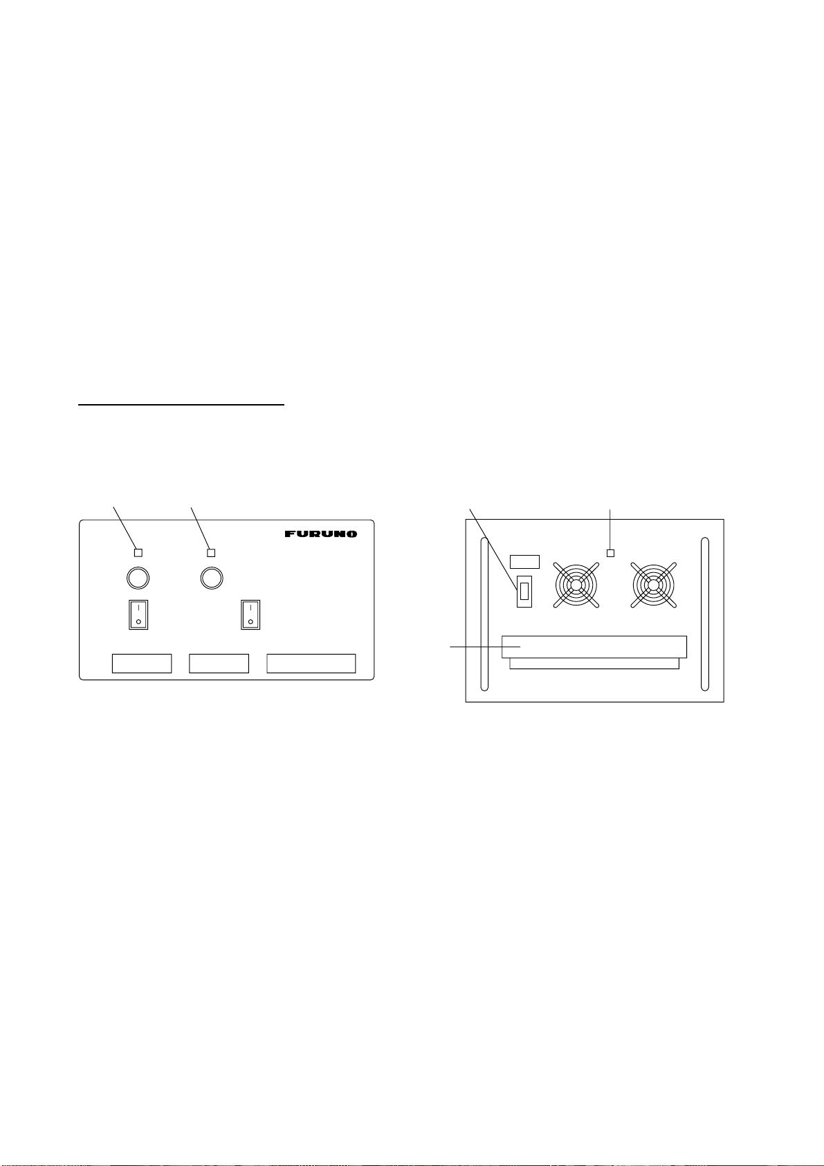
7. Push the [ E NTER] knob to open the time input window.
Position setup
INPUT TYPE: MANUAL
LAT : 34°30 NORTH
LAT : 34˚ 41 NORTH
LON : 135
LON : 135˚ 30 EAST
TIME : 09: 00 UTC
TIME: 09: 00 UTC
°
30 EAST
12 : 34
8. Enter UTC t ime with the numeric keys and then push the [ENT ER] knob. The Setup
menu appears.
9. Press the [CANCEL] key to return to the DSC standby screen.
1-6

1 OPERATIONAL OVERVIEW
1.9 System Characteristics
1.9.1 Equipment priority
Equipment priority order is as below.
1. DMC
2. Control unit sending distress alert
3. Control unit 1 – routine use
4. Control unit 2 – routine use
5. NBDP
1.9.2 Controls become inoperative
Controls become inoperative in the following conditions:
•
Controls of idle control unit in the two-control unit system when other control unit goes
OFF HOOK.
•
Controls of idle control unit in the two-control unit system when other control unit
switches to the DSC mode.
•
Distress received by DMC (Distress Message Controller).
•
NBDP is scanning or communicating.
•
Distress alert or distress relay is transmitted.
•
Call other than distress is transmitted (transmission time about 8 s). If it becomes
necessary to unlock the keyboard before the message is transmitted, press the
[CANCEL] key to cancel the call.
1.9.3 Controls become operative
Controls become operative in the following conditions:
•
[DISTRESS] button is pressed.
•
Control unit having highest priority is operated.
•
Other control unit in two-control unit system goes ON HOOK.
•
Distress received by DMC is acknowledged.
•
NBDP stops scanning or communicating.
1.9.4 Automatic setting of working frequency
The radiotelephone automatically sets working frequency in the following conditions:
•
ABLE ACK is sent in response to individual call.
•
Your ship receives ABLE ACK in response to own ship-initiated individual call.
•
Your ship sends all ship call.
•
Your ship sends distress relay.
•
Your ship sends distress alert.
•
Your ship receives group call or area call.
•
Your ship receives distress relay call.
•
Your ship receives distress alert.
1-7
1 OPERATIONAL OVERVIEW
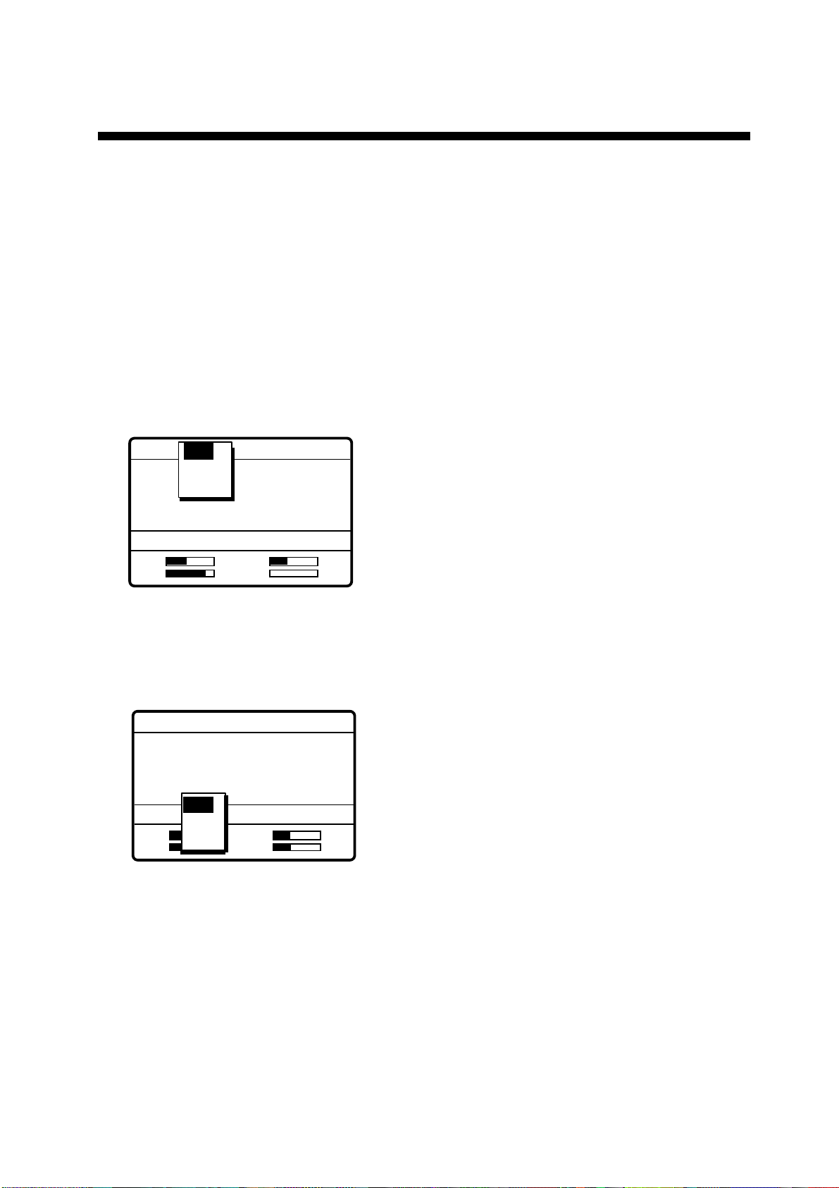
1.10 Power Supply Unit (option)
The control unit works directly on 24 VDC or through a Power Supply Unit on AC mains
supply (115 or 230 VAC). The power supply unit is type PR-300, supplying 24 VDC power
(20 A) to the FS-1570 or type PR-850A, supplying 24 VDC (40 A) to the FS-2570. Both
115/230 VAC and 24 VDC power can be connected simultaneously. In this case, the
system normally operates on the AC mains supply and when AC power is lost, the PSU
automatically switches to the DC power source.
This power supply arrangement satisfies the GMDSS requirements. The
FS-1570/FS-2570 can be operated directly from 24 VDC without a power supply.
OVEN power supp ly: The crystal oven is always powered even when the Power Switch
is OFF, provided the mains switchboard is turned on.
AC and DC power switches
Both AC and DC power switches on the PSU can be always kept on. (These switches are
provided to turn off the power supply for maintenance.) The control unit may be turned on
or off with the PSU kept on.
Red Light Green Light
PR-300
100V 10A
220V 5A
ON
OFF
LNG +- +- + -24V
Lamp (red): Lights when AC power source is in use.
Lamp (green): Lights when DC power source is in use
125V 20A
ON
OFF
AC IN DC IN DC OUT
PR-300
Terminal
Cover
Breaker
Power Lamp
POWER
ON
ON
OFF
AC INPUT 50/60Hz DC OUTPUT
PR-850A
Power supply units
Note: Both lamps light when changing to DC power supply (PR-300). These lamps also
light when the internal temperature goes too high.
1-8
2 SSB RADIOTELEPHONE
You can enter desired frequency by channel or TX and RX frequencies. The handset may
be ON HOOK or OFF HOOK. To set the SSB radiotelephone to 2182 kHz/J3E
automatically, press the [1/ RT/2182] key more than two seconds.
2.1 Transmitting
After selecting class of emission and frequency, you can transmit by pressing the PTT
switch on the handset. Output power is shown on the display.
2.1.1 Choosing class of emission
1. At the radiotelephone screen, choose class of emission (mode) as follows:
a) Rotate the [ENTER] knob to choose MODE and then push the [ENTER] knob.
MODE: SSB SIMP HIGH
CH: 800
SSB
TLX
AM
TX: 2182.0 KHZ
RX: 2182.00 KHZ
AGC : FAST
SEN
VOL
S
IA 0.0A
b) Rotate the [ENTER] knob to choose mode desired and then push the [ENTER] knob.
SSB: Single Sideband, TLX: Telex, AM: AM. (You cannot transmit on the AM mode.)
2. AGC is automatically selected according to mode. AGC FAST: SSB, AGC OFF: TLX,
AGC SLOW: AM. However, you may change it as below.
a) Rotate the [ENTER] knob to choose AGC and then push the [ENTER] knob.
MODE: SSB SIMP HIGH
CH: 200
TX: 2182.0 KHZ
RX: 2182.00 KHZ
OFF
AGC : FAST
SEN
VOL
b) Rotate the [ENTER] knob to choose OFF, SLOW or FAST as appropriate and then push
the [ENTER] knob.
FAST
FAST
SLOW
FAST
S
IA 0.0A
2-1
2 SSB RADIOTELEPHONE
2.1.2 Choosing channel, frequency
Choosing channel
1. Rotate t he [ENTER] knob to choose CH and then push the [ENTER] knob.
MODE: SSB SIMP HIGH
CH: 800
TX: 2182.0 KHZ
RX: 2182.00 KHZ
AGC : FAST
SEN
VOL
2. Channel can be ent ered directly with the numeric keys, or by using the [ENTER] knob.
See below for details.
Entering band and band channel with the numeric keys: Use the numeric keys to
enter band and band channel and then push th e [ENTER] knob.
200
S
IA
0.0A
Choosing band and band channel with the ENTER knob:
a) Use t he [FILE/CURSOR] key to place the cursor in the band or band channel position,
whichever you want to change.
200
Cursor position for
selection of band channel
200
Cursor position for
selection of band
b) Rotate the [ENTER] knob to set band (or channel) desired.
2 4 6 8 12 16 18 22 25 01 02----- 029
ITU band User band
Setting Range
ITU Band: 2/4/6/8/12/16/18/22/25
User Band: 001-029 (leadiing zero necessary)
ITU Channel: XX01 - XX236 (rendering on band or mode)
User Channel: XXX01 - XXX99
c) Push the [ENTER] knob. The TX and RX frequencies of t he channel ent ered
appear.
2-2

2 SSB RADIOTELEPHONE
N
Choosing frequency
1. Rotate the [ENTER] knob to choose TX or RX as appropriate and then push the
[ENTER] knob.
MODE: AM SIMP HIGH
CH: 200
TX: 2182.0 KHZ
2182.00 KHZ
Rx: 123456.78 KHZ
AGC : SLOW
SE
VOL
S
IA 0.0A
2. Enter frequency by one of the methods below.
Entering frequency with the numeric keys:
Use the numeric keys to enter frequency and then push the [ENTER] knob. Be sure to
including trailing zero. For example, to enter 2161 kHz, key in [2], [1], [6], [1], [0].
(Keying in 2-1-6-1 will set 216.1 kHz.)
Choosing frequency with the ENTER knob (for RX only):
a) Use the [FILE/CURSOR] key to choose digit to change.
b) Rotate the [ENTER] knob to set digit.
c) Push the [ENTER] knob.
Note: To enter same frequency for both TX and RX, enter the TX frequency first.
2.1.3 Tuning
Maximum transmission power is achieved only when the antenna impedance and
transmitter impedance match each other. Because the antenna impedance changes with
frequency, a means must be provided to match (tune) the antenna impedance with the
transmitter impedance. This is done with the antenna coupler. The antenna coupler
automatically tunes the transmitter to a wide range of different antenna lengths, from 7 to
30 m.
To initiate the automatic tuning, do the following:
1. Press the PTT switch on the handset or the [LOG/TUNE] key on the control unit.
“TUNING” appears when the [LOG/TUNE] key is pressed; “TX” pops out when the PTT
switch is pressed.
Tuning will be completed within 2 to 5 s for a newly selected frequency, or less than 0.5
s for a once-tuned frequency. (A memory saves coil and capacitor settings.) When the
tuning process is successfully completed, TUNE: OK appears. If tuning fails, TUNE:
NG appears.
2-3

2 SSB RADIOTELEPHONE
Note: When tuning is initiated in the two-control unit system, the display of the idle control
unit shows “OCCUPIED(ANOTHER CONTROLLER).” In this case, only the
DISTRESS button is operative on the idle control unit. Further, if a control unit is in
use when tuning is attempted at the other control unit, the display of the control unit
which attempted to tune shows “OCCUPIED” plus the name of the equipment in
use: ANOTHER CONTROLLER, NBDP, or DMC.
2.1.4 Using the handset
Hold the handset close to your mouth, press the PTT switch and speak clearly.
2.1.5 Monitoring transceiver output power
During transmission, the IA bar deflects according to the current being fed to the antenna
feeder from the antenna coupler. The unit of readout is amperes. The antenna current
varies with the effective antenna impedance. The swing differs by the frequency and
antenna length. The output power is proportional to the square of an antenna current.
Note: If IA is not shown, follow the procedure in paragraph 2.1.7 to show it.
MODE: SSB SIMP HIGH
CH: 200
TX: 2182.0 KHZ
RX: 2182.00 KHZ
AGC : FAST
SEN
VOL
S
IA 2.1A
Antenna Current
2-4

2 SSB RADIOTELEPHONE
2.1.6 Reducing transmitter power
To conserve energy and to minimize possible interference to other stations, reduce the
transmission power. This should be done when using the transceiver in a harbor, near the
shore or close to communication partner (other ship).
1. Rotate the [ENTER] knob to choose LOW, MID or HIGH (whichever is shown) at the
top of the screen and then push the [ENTER] knob.
MODE: SSB SIMP HIGH
CH: 200
TX: 2182.0 KHZ
RX: 2182.00 KHZ
AGC : FAST
SEN
VOL
LOW
MID
HIGH
S
IA 2.1A
FS-1570 FS-2570
LOW 68 W 70 W
MID 100 W 125 W
HIGH 150 W 250 W
2. Rotate the [ENTER] knob to choose power among LOW, MID and HIGH as
appropriate and then push the [ENTER] knob.
Note: Power amplifier temperature is monitored, and when its temperature rises above a
certain temperature output power is automatically reduced.
2.1.7 Displaying IA, IC, VC or RF
While transmitting, you may display RF (PA output), IA (antenna current), IC (collector
current) or VC (collector voltage), at the lower right corner of the radiotelephone screen.
1. Rotate the [ENTER] knob to choose RF, IA, IC or VC (whichever is displayed) at the
bottom right corner.
2. Push the [ENTER] knob.
MODE: SSB SIMP HIGH
CH: 200
TX: 2182.0 KHZ
RX: 2182.00 KHZ
AGC : FAST
SEN
VOL
IA
IC
VC
S
RF
IA 2.1A
3. Rotate the [ENTER] knob to choose option desired and then push the [ENTER] knob.
2-5

2 SSB RADIOTELEPHONE
2.2 Receiving
2.2.1 RF gain (sensitivity) adjustment
In normal use the sensitivity should be set for maximum. If the audio on the received
channel is unclear or interfered with other signals, adjust (usually reduce) sensitivity to
improve clarity.
1. Rotate the [ENTER] knob to choose SEN at the bottom of the screen and then push
the [ENTER] knob.
SEN
2. Rotate the [ENTER] to adjust and then push the [ENTER] knob.
2.2.2 S-meter
The S-meter shows relative signal strength coming into the receiver frontend. Note that
the S-meter does not function when the AGC is turned off.
MODE: SSB SIMP HIGH
CH: 200
TX: 2182.0 KHZ
RX: 2182.00 KHZ
AGC : FAST
SEN
VOL
2.2.3 Monitoring traffic on intended transmit frequency
When a semi-duplex channel is selected, it is recommended to monitor if there is no
existing traffic on the frequency you are going to use. To do this, choose RX and then
push the [ENTER] knob. The transceiver monitors traffic on the selected frequency for
three s.
2.2.4 Receiving AM broadcasting stations
1. Press the [1/ RT/2182] key to show the radiotelephone screen.
2. Rotate the [ENTER] knob to choose MODE and then push the [ENTER] knob.
MODE: SSB SIMP HIGH
CH: 800
SSB
TLX
AM
TX: 2182.0 KHZ
S
IA 0.0A
S-meter
RX: 2182.00 KHZ
AGC : FAST
SEN
VOL
S
IA 0.0A
3. Rotate the [ENTER] knob to choose AM and then push the [ENTER] knob.
4. Rotate the [ENTER] knob to choose RX and then push the [ENTER] knob.
2-6

2 SSB RADIOTELEPHONE
N
MODE: AM SIMP HIGH
CH: 200
TX: 2182.0 KHZ
2182.00 KHZ
Rx: 123456.78 KHZ
AGC : SLOW
SE
VOL
S
IA 0.0A
5. Key in RX frequency with the numeric keys and then push the [ENTER] knob.
2.2.5 Squelch control, squelch frequency
Squelch on/off
The squelch mutes the audio output in the absence of an incoming signal. Press the [5/
ACK/SQ key] to turn on and off the squelch alternately. When radio noise is too jarring
during stand-by condition, it may be muted by activating the squelch. “SQ” appears when
the squelch function is active.
Squelch frequency
1. At the radiotelephone screen, press the [#/SETUP] key.
Setup menu
****
NB : OFF
SQ FREQ : 600 HZ
FAX RX ENABLE : OFF
USER CH
SYSTEM
****
2. Rotate the [ENTER] knob to choose SQ FREQ.
3. Push the [ENTER] knob.
4. Enter frequency (range: 500-2000 Hz, default 800 Hz) with the numeric keys and then
push the [ENTER] knob.
5. Press the [CANCEL] key to return to the radiotelephone screen.
2.2.6 Noise blanker
The noise blanker functions to remove noise. You may turn it on or off as follows:
1. At the radiotelephone screen, press the [#/SETUP] key.
2. Rotate the [ENTER] knob to choose NB.
3. Push the [ENTER] knob.
4. Rotate the [ENTER] knob to choose ON or OFF as appropriate and then push the
[ENTER] knob.
5. Press the [CANCEL] key to return to the radiotelephone screen.
2-7

2 SSB RADIOTELEPHONE
2.3 Intercom
The built-in intercom permits voice communications between two FS-2570C Control Units.
1. Press the [1/ RT/2182] key to show the radiotelephone screen.
2. Off hook the handset.
3. Press the [4/IntCom] key to show INTERCOM on the display. The called party’s
handset rings.
4. When the called party picks up their handset, press the PTT switch on the handset and
speak into the handset.
Hang up the handset to turn the intercom off. The indication INTERCOM disappears from
the screen.
2.4 Telex Communications
Telex communication is performed with the NBDP Terminal Unit (option) connected to this
radiotelephone. No special operation is required on the control unit; class of emission and
frequencies are set on the NBDP Terminal Unit. For telex communications, see Chapters 8
through 11.
2-8

2 SSB RADIOTELEPHONE
2.5 When Automatic Tuning Fails
The antenna coupler automatically tunes a wire or whip antenna to the transceiver. When
all frequencies cannot be tuned, TUNE OK will not appear on the display. In this case, you
can tune 2182 kHz by manually operating t he coupler as shown in the procedure below.
DANGER
HIGH TENSION HAZARD
DO NOT TRANSMIT WHEN
THE ANTENNA COUPLER
IS OPEN.
1. Turn off the control unit. Remove the cover of the antenna coupler.
2. Set the MANUAL-AUTO switch to t he MANUAL position.
COUPLER BOARD
DUMMY
LOAD
BOARD
3. Replac e the cover.
4. Turn on the control unit.
MANUAL
AUTO
2-9

2 SSB RADIOTELEPHONE
2.6 User Channels
The USER CH menu allows registration of user TX and RX channels, where permitted by
the Authorities.
NOTICE
FURUNO will assume no responsibility
for the disturbance caused by the
unlawful or improper setting of user
channels.
2.6.1 Registering user channels
“USER CH” in the System setup menu must be enabled in order to register user channels.
For further details, contact your dealer.
1. At the radiotelephone screen, press the [#/SETUP] key.
Setup menu
****
NB : OFF
SQ FREQ : 600 HZ
FAX RX ENABLE : OFF
USER CH
SYSTEM
****
2. Rotate the [ENTER] knob to choose USER CH and then push the [ENTER] knob. The
window shown below appears.
ENTRY
ERASE
3. ENTRY is selected; push the [ENTER] knob.
User ch entry
***
3
MODE: SSB
00201. TX: 2111.5 RX: 2111.5
00202. TX: 2222.0 RX: 2222.0
00203. TX: 2333.5 RX: 2333.5
00204. TX: 2444.0 RX: 2444.0
00205. TX: 2555.5 RX: 2555.5
5UP6
DOWN
4
**
CH: 2-01
4. Push the [ENTER] knob to open the user channel options window.
User ch entry
2-10
***
3
MODE: SSB 4CH: 2-01
00201. TX: 2111.5 RX: 2111.5
00202. TX: 2222.0 RX: 2222.0
00203. TX: 2333.5 RX: 2333.5
00204. TX: 2444.0 RX: 2444.0
00205. TX: 2555.5 RX: 2555.5
5UP6
MODE
CH
FREQ
DOWN
**

2 SSB RADIOTELEPHONE
5. Rotate the [ENTER] knob to choose MODE and then push the [ENTER] knob.
User ch entry
***
3
MODE: 4CH: 2-01
00201. TX: 2111.5 RX: 2111.5
00202. TX: 2222.0 RX: 2222.0
00203. TX: 2333.5 RX: 2333.5
00204. TX: 2444.0 RX: 2444.0
00205. TX: 2555.5 RX: 2555.5
5UP6
SSB
NBDP
DSC
DOWN
**
6. Rotate the [ENTER] knob to choose appropriate mode among SSB, NBDP and DSC
and then push the [ENTER] knob.
User ch entry
***
3
MODE: SSB
00201. TX: 2101.5 RX: 2101.5
00202. TX: 2202.0 RX: 2202.0
00203. TX: 2303.5 RX: 2303.5
00204. TX: 2404.0 RX: 2404.0
00205. TX: 2505.5 RX: 2505.5
5UP6
DOWN
**
4
CH : 2-01
CH:0−00
- 256 channels may be registered.
- Band no. setting range is 0-29 and band channel no. range is
01-99.
- For DSC, four channels can be registered per band (2, 4, 6
8, 12, 16, 18, 22, 25).
- "0" band is for DSC frequencies only, and they are registered
under "OTHER." Four channels are available, 01-04.
7. Key in channel no. and then push the [ENTER] knob. For example, press [0], [1], [2],
[3], [4] and then push the [ENTER] knob to enter channel 01234.
User ch entry
**
3
MODE : SSB
01234. TX: 0.0 RX: 0.0
01240. TX: 12666.0 RX: 13666.0
01241. TX: 12777.5 RX: 13777.5
01242. TX: 12999.5 RX: 13999.5
01250. TX: 12100.0 RX: 13100.0
5UP6
TX : 0.0 KHZ
RX : 0.0 KHZ
DOWN
**
4
CH : 12-34
8. Enter TX frequency with the numeric keys.
9. Rotate the [ENTER] knob to choose RX.
10. Enter RX frequency with the numeric keys and then push the [ENTER] knob.
11. Rotate the [ENTER] knob to display all channels entered.
12. Press the [CANCEL] key twice to return to the radiotelephone screen.
2-11

2 SSB RADIOTELEPHONE
2.6.2 Deleting user channels
Deleting individual us e r cha nne ls
1. At the radiotelephone screen, press the [#/SETUP] key.
2. Rotate the [ E NTER] knob to choose USER CH and then push the [ENTER] knob.
3. Rotate the [ E NTER] knob to choose ENTRY and then push the [ENTER] knob.
4. Push the [ENTER] knob, rotate the [ENTER] knob to choose CH and then push the
[ENTER] knob.
5. Enter channel number to process and then push the [ENTER] knob.
6. Tx and Rx f r equencies are shown as “0.0 kHz”; push the [ENTER] knob to delete
channel.
7. Press the [CANCEL] key twice to return to the radiotelephone screen.
Deleting all user channel s
1. At the radiotelephone screen, press the [#/SETUP] key.
2. Rotate the [ E NTER] knob to choose USER CH and then push the [ENTER] knob.
3. Rotate the [E NTER] knob to choose ERASE and then push the [ENTER] knob.
4. Rotate the [ E NTER] knob to choose YES and then push the [ENTER] knob.
5. Press the [CANCEL] key to return to t he radiot elephone screen.
2.7 FAX Enable/Disable
You may enable or disable FAX use as follows:
1. At the radiotelephone screen, press the [#/SETUP] key to open the Set up menu.
2. Rotate the [E NTER] knob to choose FAX RX ENABLE and then push the [ENTER]
knob.
3. Rotate the [ E NTER] knob to choose ON or OFF as appropriate and then push the
[ENTER] key.
MODE: SSB SIMP HIGH
CH: 800
TX: 2182.0 KHZ
RX: 2182.00 KHZ
SEN
VOL
4. Press the [CANCEL] key to close the m enu.
SSB
TLX
FAX
AM
AGC : FAST
S
IA
0.0A
2-12

3 DSC OVERVIEW
3.1 What is DSC?
DSC is an acronym meaning Digital Selective Calling. It is a digital distress and general
calling system in the MF and HF bands used by ships for transmitting distress alerts and
general calls and by coast stations for transmitting the associated acknowledgements.
For DSC distress and safety calling in the MF and HF bands, the frequencies are (kHz)
2187.5, 4207.5, 6312.0, 8414.5, 12577.0, and 16804.5.
The DSC station sends and receives DSC general and safety calls via the radiotelephone.
Distress Frequency
Routine DSC Call
Distress alert, routince DSC call
Routine DSC Calls
TRANSCEIVER
Option
(FS-2570
only)
UNIT
FS-1570T
FS-2570T
CONTROL UNIT
FS-2570C
3.2 DSC Call
DSC calls are roughly divided in two categories: distress and safety calls, and routine calls.
Below are the types of DSC calls.
Call Description
All Ships Call to all ships
Distress Your ship sends distress call
Distress relay all Your ship relays distress call to all ships
Distress relay select Your ship relays distress call to a coast station
Geographical Area Call to all ships in a specific geographical area
Group Call to a specific group
Individual Call to a specific address
Medical Transport Inform all ships that your ship is carrying medical supplies
Neutral Craft Inform all ships that your ship is not a participant in armed conflict
Polling Call to determine if own ship is in communicating range with other
ship
Position 1) You send your position to other stations
2) Your ship requests position of other station
PSTN Call over Public Switched Telephone Network (PSTN)
Test Send test signal to a coast station to test your station’s functionality
3-1

3 DSC OVERVIEW
Contents of a DSC call
•
Calling category
Call category Call
Individual Individual, PSTN, Test, Position, Polling,
Relay Sel (specific coast station)
All Ships All Ships, Neutral, Medical, Relay All
Group Group
Geographical Area Area
Distress Call Distress
• Station ID
Own ship ID and sending station ID. Coast station ID begins with 00; Group ID
begins with 0.
• Priority
Distress: Grave and imminent danger and request immediate assistance.
Safety: A station is about to transmit a call containing an important
navigational or meteorological warning.
Urgency: A calling station has a very urgent call to transmit concerning safety of
ship, aircraft or other vehicle or safety of person.
Business: Communication related to the navigation, movements and needs of ships
and aircraft.
Routine: General calling
• Communication type
Telephone: Telephone (J3E) by SSB radiotelephone
NBDP-ARQ: Telex (J2B) mode ARQ via NBDP Terminal Unit
NBDP-FEC: Telex (J2B) mode FEC via NBDP Terminal Unit
• Communication frequency
Working frequency used to call by telephone or NBDP. The sending station may have
the receiving frequency (ship or coast station) assign the frequency to use.
• Position
Position can be automatically or manually sent.
• DSC frequency
DSC frequency to use. If the call category is SAFETY, URGENCY or DISTRESS,
choose a DSC distress frequency.
• End code
The end of a DSC call is denoted by ACK RQ (Acknowledge Request), ACK BQ
(Acknowledge Back) or EOS (End of Sequence).
3-2

3 DSC OVERVIEW
3.2.1 Distress alert call and reply
This type of call is sent by own ship in the event of distress, by using the [DISTRESS]
button as follows:
1. The LED in the [DISTRESS] button initially flashes, and lights when the button is
pressed more than three seconds. (If the button is pressed less than three seconds,
the distress alert is not sent. Once the alert is sent it cannot be cancelled.)
NOTICE
IN CASE OF ACCIDENTAL TRANSMISSION OF THE DISTRESS ALERT
If the distress is accidentally transmitted,
contact the nearest coast station and inform
them of the accidental transmission as
follows:
a) Ship's name
b) Ship's call sign and DSC number
c) Position at time of transmission
d) Time of transmission
2.
The radiotelephone automatically sets the DSC distress frequency and then the
equipment transmits the distress alert.
3. After the distress alert is transmitted (this takes about 40 seconds), the equipment
waits for the distress acknowledgement call (DIST ACK) from a coast station. This
usually takes less than three minutes. (If it is not received within 4.5 minutes, the
distress alert is re-transmitted.)
4. The radiotelephone automatically sets the distress communication frequency to use to
conduct voice communications (telex also available) with the coast station.
(1)
(2)
Own Ship
(3)
(1)
Ship in
Distress
(Own Ship)
(2)
(3)
Coast
Station
(1) Ship in distress sends Distress Alert
(2) Coast station sends distress acknowledgement (DIST ACK).
(3) Voice or telex communications between ship in distress and coast station
3-3

3 DSC OVERVIEW
3.2.2 Individual call
The individual call is for sending a call to a specific station.
(1)
(2)
(3)
(1) DSC Message [Called Acknowledge
Request (ACK RQ) Signal]
Own Ship
(2) Acknowledge Back (ACK BQ) Signal
(3) Voice or telex communication
Coast
Station
Basic procedure (radiotel ephone)
1. Prepare call and transmit it by pressing the [CALL] key. The equipment then awaits
acknowledgement of the call.
2. Receive acknowledge back (ACK BQ) signal from other party (coast station or ship
station) within about five minutes. The audio alarm sounds at this time; press the
[CANCEL] key to silence it.
3. After receiving the ACK BQ signal, communicate with other party; the radiotelephone
automatically sets the working frequency and class of emission you specified.
3.3 Audio A larms
When you receive a distress alert or routine call addressed to your ship, the audio and
visual alarms are released. For the distress or urgency call, the audio alarm sounds until
the [CANCEL] key is pressed, and sounds for one second and then automatically goes off
in case of other calls. The tone of the alarm changes with the call received. By becoming
accustomed to the tone, you can know which type of call you have received.
Alarm Frequency (interval)
Safety call received 1300 Hz and 0 Hz (250 ms)
Routine, Ship's Business call
received
While DISTRESS button is
pressed for three s
Distress alert sent 2200 Hz, continuous
Own ship position not updated
Distress alert, urgency
message received
880 Hz and 440 Hz (500 ms)
2200 Hz and 0 Hz (125 ms)
2200 Hz (50 ms), three beeps
every two s
1300 Hz and 2200 Hz (250 ms)
3-4

3 DSC OVERVIEW
3.4 Interpreting Call Displays
This paragraph provides the information necessary f or int erpreting receive and send call
displays.
3.4.1 Receive calls
Below are sample distress and individual receive calls. The content of other types of
receive calls is similar to that of t he individual call. When you receive a call, the message
“INCOMING” flashes at the bott om of the display.
Distress receive call
Received message
*
MAR-23-2002-23:59 ECC: OK
DISTRESS CALL
SHIP IN DIST:
NATURE: UNDESIGNATED
POS:
12°34N 123°45E AT 12:34
TELEPHONE
ANSWER
Push [ENTER] knob
to switch.
Received message
*
5
DISTRESS COORDINATES:
12°34N 123°45E AT 12:34
TELECOMMAND: J3E TELEPHONE
END OF SEQUENCE: EOS
ERROR-CHECK: OK
DSC FREQUENCY : 2177.0KHZ
Rotate [ENTER] knob
to switch.
Received message
*
FORMAT : DISTRESS CALL
SELF-IDENTITY : 123456789
NATURE OF DISTRESS:
UNDESIGNATED DISTRESS
123456789
ALL VIEW
34
GO TO EASY VIEW
*
2182.0 KHZ
*
*
Date and time of message
ECC (Error Check Character): OK or NG (No Good)
Category (Distress call)
Ship in Distress (ID No. of ship in distress)
Nature of Distress (Undesignated, Fire, Flooding,
Collision, Grounding, Listing, Sinking, Disable,
Abandoning, Piracy, Man Overboard, EPIRB emission)
Position of ship in distress
Working frequency to use
Distress coordinates (position of ship in distress)
Telecommand (class of emission)
End of sequence (EOS for distress)
Error check (OK or NG)
DSC frequency used to transmit distress call
Format (distress)
ID no. of ship in distress
Nature of distress (problem with ship in distress, see above)
5
3-5

3 DSC OVERVIEW
Individual receive c all
Received message
*
MAR-23-2002-23:59 ECC: OK
INDIVIDUAL REQUEST
FROM SHIP:
ROUTINE TX: 2182.0 KHZ
TELEPHONE RX: 2182.0 KHZ
ANSWER3 4ALL VIEW
Push [ENTER] knob
to switch.
Received message
*
WORKING FREQ. : TX: 2182.0 KHZ
RX:
END OF SEQUENCE: ACK. RQ
ERROR-CHECK: OK
DSC FREQUENCY 2177.0KHZ
Rotate [ENTER] knob to
go to "GO TO EASY VIEW"
or push it to go to previous display.
Received message
*
FORMAT : INDIVIDUAL
ADDRESS : 987654321
CATEGORY : ROUTINE
SELF-IDENTITY : 123456789
1ST TELECOMMAND: J3E TELEPHONE
2ND TELECOMMAND : NO INFORMATION
123456789
GO TO EASY VIEW
*
*
2182.0 KHZ
*
Date and time of message
ECC (Error Check Character): OK or NG (No Good)
Able acknowledge ("Unable acknowledge" and reason if unable)
ID No. of sending station
Category (Routine, Business, Safety, Urgency)
Working frequency to use
Note: ANSWER is for replying to message.
Working frequency to use
End of sequence (ACK. BQ or ACK. RQ)
Error check (OK or NG)
DSC frequency used
Format (individual)
ID of your station
Category (Routine, Business, Safety, Urgency)
ID of sending station
1st Telecommand (class of emission)
2nd Telecommand (class of emission)
3-6

3 DSC OVERVIEW
3.4.2 Send calls
Below are sample distress and individual send calls. The content of other types of send
calls is similar to that of the individual call.
Distress send call
Distress
call in progress!
NATURE: UNDESIGNATED
12°34N 123°45E AT 12:34
POS:
TELEPHONE
DSC FREQ :
TIME TO GO : 30S
2182.0 KHZ
2187.5 KHZ
Individual sen d call
Compose message
**
CALL TYPE: INDIVIDUAL
STATION ID: 123456789
PRIORITY
COM. TYPE : TELEPHONE
COM. FREQ : CH 401
DSC FREQ : 2M-INTL
Rotate [ENTER] knob to
choose GO TO ALL VIEW
and then push it.
**
WORKING FREQ. : CH 401
: ROUTINE
GO TO ALL VIEW
Compose message
**
**
Nature of Distress (Undesignated, Fire, Flooding,
Collision, Grounding, Listing, Sinking, Disable,
Abandoning, Piracy, Man Overboard)
Position of ship in distress (your ship)
Working frequency to use
DSC frequency used to send distress call
Time to go until distress alert is transmitted
Call type (Individual)
ID of station where message is to be sent
Priority (Routine, Business, Safety, Urgency)
Mode of communication (Telephone, NBPD-ARQ, NBDP-FEC)
Working channel (or frequency)
DSC frequency
Working frequency
END OF SEQUENCE: ACK. RQ
DSC FREQUENCY TX: 2177.0 KHZ
RX: 2177.0 KHZ
Rotate [ENTER] knob.
Compose message
*
FORMAT : INDIVIDUAL
ADDRESS : 987654321
CATEGORY : ROUTINE
SELF-IDENTITY : 123456789
1ST TELECOMMAND: J3E TELEPHONE
2ND TELECOMMAND : NO INFORMATION
GO TO EASY VIEW
*
End of sequence (Acknowledge request)
DSC frequency used
Calling format
Own ship ID
Communications category
ID no. of transmitting station
1st telecommand
2nd telecommand
3-7

3 DSC OVERVIEW
(This page intentionally left blank.)
3-8

4 DISTRESS OPERATIONS
4.1 Sending Distress Alert
GMDSS ships carry a DSC terminal with which to transmit the distress alert in the event of
a life-endangering situation. A coast station receives the dist ress alert and sends the
distress alert acknowledge call to the ship in distress. Then, voice or telex
communications bet ween the ship in distress and coast st ation begins.
Transmission of the distress alert and receiving of the distress alert acknowledgement are
completely automatic - simply press the [DISTRESS] button to initiate the sequence.
Russian version
Audio alarm is released continuously after transmitting distress alert.
•
The [CANCEL] key can be used during the transmission of the distress alert. The
•
transmission sequence is stopped at the end of the fifth transmission.
4.1.1 Sending distress alert by DISTRESS button, nature of distress
not specified
1. Open the DISTRESS button cover and press and hold down the [DISTRESS] button
more than three seconds. The button flashes in red and the buzzer sounds rapidly. The
display shows the contents of the distress alert call: your ship’s nature of distress,
position, time and the DSC frequency over which the alert has been transmitted.
The number of seconds to cont inue pressing the [DISTRESS] button appear at the
bottom of the display. The buzzer sounds continuously and the lamp in the button lights
when the button has been pressed three seconds. You can release the button at that
time.
Distress button
pressed!
Nature of Distress
Position, Time
DSC Distress
Frequency used
to transmit the
distress alert
NATURE: UNDESIGNATED
12°34N 123°45E AT 12:34
POS:
TELEPHONE
DSC FREQ :
KEEP PRESSED FOR 3S
2182.0 KHZ
2187.5 KHZ
Displays number of seconds to continue
pressing the [DISTRESS] button to
transmit the distress alert.
4-1

4 DISTRESS OPERATIONS
2.
The display changes as below. It takes about 40 seconds to transmit the distress alert,
and the number of seconds until transmission is completed is shown at the bottom of
the display. At this time the output power of the radiotelephone is automatically set to
maximum.
Distress
call in progress!
NATURE: UNDESIGNATED
12°34N 123°45E AT 12:34
POS:
TELEPHONE
DSC FREQ :
TIME TO GO : 38S
3.
After the distress alert has been sent, t he display changes as below and the audio
2182.0 KHZ
2187.5 KHZ
Time to go until distress
alert is completely transmitted.
alarm is stopped. Wait to receive the dist ress acknowledge call from a coast station,
which usually takes 1 to 2 min 45 seconds. (The [DISTRESS] button remains lit until
the equipment receives the distress acknowledge call from a coast station.) The timer
counts down the number of minutes before next retransmission (if necessary), from
3.5 to 4.5 minutes, randomly set.
At this time, the equipment cannot receive any calls except the distress alert
acknowledge call. The distress alert you sent is recorded in the TX log.
Wait for distress
acknowledgement.
NATURE: UNDESIGNATED
POS:
12°34N 123°45E AT 12:34
TELEPHONE
DSC FREQ :
TIME TO GO: 2M10S
4.
When the distress acknowledge call is received, the audio alarm sounds and the
2182.0 KHZ
2187.5 KHZ
display changes as below.
Distress acknowledge
call received.
FROM COAST:
SHIP IN DIST:
NATURE: UNDESIGNATED
12°34N 123°45E AT 12:34
POS:
TELEPHONE
Note:
If you do not receive the distress alert acknowledge call, the equipment
001234567
123456789
2182.0 KHZ
STOP ALARM
automatically re-transm it s the distress alert and then awaits the distress alert
acknowledge call. This is repeated until the distress alert is acknowledged.
5.
Silence the alarm with the [CANCEL] key. The contents of the distress acknowledge
call appear.
4-2

4 DISTRESS OPERATIONS
Received message
JAN-23-2002-23:59 ECC: OK
DISTRESS ACKNOWLEDGE
FROM COAST:
SHIP IN DIST:
NATURE: UNDESIGNATED
12°34N 123°45E AT 12:34
POS:
TELEPHONE
6.
Communicate with the coast station via radiotelephone, following the instructions
001234567
123456789
2182.0 KHZ
GO TO ALL VIEW
below. The radiotelephone automatically sets working frequency and cl ass of em ission,
as specified in the distress acknowledge call.
a) Say MAYDAY three times.
b) Say “This is … “ name of your vessel and call sign three
times.
c) Give nature of distress and assistance needed.
d) Give description of your vessel (type, color, number of persons onboard, etc.).
4.1.2 Sending distress alert by DISTRESS button, nature of distress
specified
If you have the time to designate the nature of distress, send the distress alert as follows:
1.
Open the DISTRESS button cover and press the [DISTRESS] button momentarily to
show the following display.
Compose message
**
CALL TYPE
NATURE
POS.
COM.TYPE
DSC FREQ
UNDESIGNATED
FIRE
FLOODING
COLLISION
GROUNDING
LISTING
6
: All ships
: 987654321
:Undesignated
:
:
**
Rotate [ENTER] knob to scroll.
6
SINKING
DISABLE
ABANDONING
PIRACY
MAN OVERBOARD
Rotate the [ENTER] knob to choose nature of distress and then push the [ENTER]
2.
knob.
3.
Push the [ENTER] knob to open the POS. menu. This is where you enter your position,
automatically or manually. The INPUT TYPE option, that is, the source of position data,
is selected to AUTO, MANUAL or NO INFO. For AUTO, if the position is correct, push
the [ENTER] knob twice and go to step 10. For manual input, or you do not know your
position, go to step 4.
INPUT TYPE: AUTO
LAT : 34
LON : 135
TIME: 09: 00 UTC
°
41 NORTH
°
30 EAST
Note: If the message “No Position Data” appears when you change INPUT TYPE
from MANUAL to AUTO, confirm that the navigation device is f unctioning and
then choose AUTO again.
4-3

4 DISTRESS OPERATIONS
4. Push the [E NTER] knob to open the INPUT TYPE menu.
INPUT TYPE: AUTO
LAT : 34
LON : 135
TIME: 09: 00 UTC
AUTO
°
41 NORTH
N
MANUAL
°
30 EAST
NO INFO
5.
Rotate the [ENTER] knob to choose MANUAL and then push the [ENTER] knob. If you
cannot confirm your position, choose NO INFO, push the [ENTER] knob and then go
to step 10.
6.
Push the [ENTER] knob to open the latitude input window. Use the numeric keys to
enter latitude (in four digits). (If necessary, switch coordinates: [1] key to switch to
North; [2] key to switch to South.) Push the [ENTER] knob.
INPUT TYPE: MANUAL
LAT : 34° 41 NORTH
34˚ 41
LON : 135
TIME: 09: 00 UTC
34 ° 00 N
12
°
30 EAST
After last digit
is entered
35°00 N
12
NORTH: [1] KEY
SOUTH: [2] KEY
Push the [ENTER] knob to open the longitude input window. Use the numeric keys to
7.
enter longitude (in five digits). (If necessary, switch coordinates: [1] key to switch to
East; [2] key to switch to West.) Push the [ENTER] knob.
INPUT TYPE: MANUAL
LAT : 35
LAT: 34˚ 41 NORTH
LON : 135° 30 EAST
LON : 135˚ 30 EAST
TIME: 09: 00 UTC
°
00 NORTH
135°30 E
12
After last digit
is entered
135°00 E
12
EAST: [1] KEY
WEST: [2] KEY
Push the [ENTER] knob to open the time input window.
8.
INPUT TYPE: MANUAL
LAT : 35
LAT : 34˚ 41 NORTH
LON : 135
LON : 135˚ 30 EAST
TIME : 09: 00 UTC
TIME: 09: 00 UTC
9.
Key in UTC time with the numeric keys and then push the [ENTER] knob.
°00 NORTH
° 00 EAST
12 : 34
Note: If you cannot confirm time, enter 88:88 to input NO INFO as the time.
4-4

4 DISTRESS OPERATIONS
10.
The COMPOSE MESSAGE screen is redisplayed. Push the [ENTER] knob to open the
COM. TYPE menu.
Compose message
**
DISTRESS
CALL TYPE:
NATURE: FLOODING
POS: 35
COM. TYPE: TELEPHONE
DSC FREQ : 2187.5 KHZ
11.
Rotate the [ENTER] knob to choose TELEPHONE or NBDP-FEC as appropriate and
TELEPHONE
°00
N 135˚00E AT 23:25
NBDP-FEC
GO TO ALL VIEW
**
then push the [ENTER] knob. (Telephone is the usual mode, however NBDP may also
be used.)
12.
Push the [ENTER] knob to open the DSC FREQ menu.
Compose message
**
CALL TYPE:
NATURE: FLOSIGNATED
POS: 35
COM. TYPE: TELEPHONE
DSC FREQ : 2187.5 KHZ
Rotate the [ENTER] knob to choose a DSC frequency (normally 2187.5 kHz) and then
13.
°00
AUTO
DISTRESS
2187.5
4207.5
6312.0
N 135˚00E AT 23:34
8414.5
12577.0
16804.5
GO TO ALL VIEW
**
push the [ENTER] knob. (AUTO retransmits the distress alert on the distress and
safety frequencies 2 MHz, 8 MHz, 16 MHz, 4 MHz, 12 MHz and 6 MHz in that order if
the distress alert is not acknowledged.)
14.
The display changes as below (example).
Compose message
DISTRESS
CALL TYPE:
NATURE: FLOODING
POS: 35
COM. TYPE : TELEPHONE
DSC FREQ : 2187.5 KHZ
°00
N 135°00E AT 12:34
GO TO ALL VIEW
15.
Press the [DISTRESS] button more than three seconds to send the distress alert.
Distress
call in progress!
NATURE: FLOODING
35°00N 135°00E AT 12:34
POS:
TELEPHONE
DSC FREQ :
TIME TO GO : 38S
For telephone, follow steps 3 to 6 on page 4-2 and 4-3. For NBDP, follow the
16.
2182.0 KHZ
2187.5 KHZ
procedure below.
4-5

4 DISTRESS OPERATIONS
Communicating by NBDP Terminal Unit
1. The message “STATION ENTRY COMPLETED FROM DSC. Press any key to
escape.” appears on the NBDP’s display. Press any key on the NBDP Terminal Unit to
erase the message.
2. Press the function key [F3] on the keyboard of the NBDP Terminal Unit to show the
Operate menu.
3. Choose “Call Station” and then press the [Enter] key.
Call Station
Station List
DSC
ABC-6M
ABC-12M
ABC-8M
FURUNO
Station : DSC
ID Code :
Mode : ARQ FEC
Tx Freq : 2174.50
Rx Freq : 2174.50
Station Set up
4. “DSC” is selected; press the [Enter] key to connect the communications line.
5. “Connect” appears in reverse video. Type and transmit your message, giving the
following information:
a) Ship’s name and call sign
b) Nature of distress and assistance needed
c) Description of your vessel
6. Press the function key [F10] (BREAK) to disconnect the line.
4.2 Receiving a Distress Alert
When you receive a distress alert from a ship in distress, the audio alarm sounds and the
message "Distress call received." appears on the display. Press the [CANCEL] key to
silence the audio alarm. Wait for the distress acknowledge call from a coast station. If you
do not receive the distress acknowledge call from a coast station, which usually takes
about five minutes from the time of reception of a distress alert, follow the appropriate flow
chart in this section to determine your course of action.
Note: An asterisk (*) appearing in a distress alert call indicates error at asterisk location.
Russian version
If another distress alert or urgent call is received just after pressing the [CALL] key (for
distress alert relay and distress acknowledgement), the most recently received call has
priority.
4-6

4 DISTRESS OPERATIONS
4.2.1 Distress alert received on MF band
Do the following:
• Continue watching on 2182 kHz. Wait for coast station to acknowledge the distress call.
Watch until “SEELONCE FINI” is announced.
• If multiple DSC distress alerts are received from the same ship in distress and it is
beyond a doubt in your vicinity, a DSC acknowledgement may, after consultation with an
RCC or Coast Station, be sent to terminate the call by DSC.
• In no case is a ship permitted to transmit a DSC distress relay call upon receipt of a
DSC distress alert on MF channel 2187.5 kHz.
Action for ship receiving distress alert on MF band
DSC Distress alert received.
Press [CANCEL] key to
silence alarm.
Listen on 2182 kHz
for 5 minutes.
Did you receive
acknowledge from
CS and/or RCC?
Yes
CS = Coast Station
RCC = Rescue Co-ordination Center
No
Is distress traffic
in progress?
Yes
Is own
vessel able
to aid
ship in
distress?
No
No
Is the DSC distress
call continuing?
Yes
Acknowledge the alert by
Yes
radiotelphony to the ship
in distress on 2182 kHz.
No
Enter details in log.
Inform CS and/or RCC.
4-7

4 DISTRESS OPERATIONS
Sending the distress ackn owledge call to sh ip in distress (on MF band)
Transmit the distress acknowledge call to the ship in distress only when you do not
receive it from a coast station and
you are able to aid the ship in distress
. First,
transmit the distress acknowledge to the ship in distress by telephone. If the DSC call is
continuing, terminate transmission of the distress alert as follows:
1. The audio alarm sounds and the display shows the message “Distress call received.”
when your ship receives a distress call.
Distress
call received.
DISTRESS CALL
SHIP IN DIST:
NATURE: UNDESIGNATED
POS:
TELEPHONE
12°34N 123°45E AT 12:34
123456789
2182.0 KHZ
STOP ALARM
2. Press the [CANCEL] key to silence the audio alarm and the display changes as below.
Received message
*
JAN-23-2002-23:59 ECC: OK
DISTRESS CALL
SHIP IN DIST:
NATURE: UNDESIGNATED
POS:
TELEPHONE
ANSWER
If you do not receive the distress acknowledge call from a co ast station and you
3.
12˚34N 123˚45E AT 12:34
34
have received the distress alert more than twice,
123456789
ALL VIEW
*
2182.0 KHZ
contact the ship in distress over
radiotelephone. If the distress alert continues, terminate the alert by rotat ing the
[ENTER] knob to choose ANSWER, push the [ENTER] knob and then go to step 4 to
send the distress acknowledge call to the ship in distress.
4. Push the [E NTER] knob to open the CALL TYPE menu.
Compose message
**
CALLTYPE
COAST
ID IN
DSC FREQ : 2182.0 KHZ
RELAY ALL
RELAY COAST
ACKNOWLEDGE
GO TO ALL VIEW
**
5. Rotate the [ENTER] knob to choose ACKNOWLEDGE and then push the [ENTER]
knob. The following display appears.
Compose message
**
CALL TYPE : ALL SHIPS
DISTRESS ACKNOWLEDGE
ID IN DIST :
DSC FREQ :
4-8
GO TO ALL VIEW
123456789
2182.0 KHZ
**

4 DISTRESS OPERATIONS
6. Press the [CALL] key, and the message “Category distress transmit sure?” appears.
Continue press the key until the message “Distress acknowledge call in progress
appears, to transmit the distress acknowledge call to the ship in distress.
Category distress
transmit sure?
ID IN DIST:
DSC FREQ :
KEEP PRESSED FOR 3S
123456789
2187.5 KHZ
[CALL] key
pressed
3 seconds
Distress acknowledge
call in progress!
SHIP IN DIST :
DSC FREQ :
123456789
2187.5 KHZ
TIME TO GO 4S
4.2.2 Distress alert received on HF band
If you receive a distress alert on the HF band, the ALARM lamp lights and the audio alarm
sounds. Press the [CANCEL] key to silence the audio alarm. Wait for the distress
acknowledge from a coast station. If you do not receive the distress acknowledge within
five minutes, follow the instructions below to determine your course of action.
• Watch on the distress frequency.
• Relay the distress alert in the following cases:
- You have not received a distress acknowledge call from a coast station within five
minutes after receiving a distress call.
- You have not received a distress relay from other ship.
- You cannot receive distress communications from other ship over radiotelephone.
- If it is clear the ship or persons in distress are not in the vicinity and/or other crafts are
better placed to assist, superfluous communications which could interfere with search
and rescue activities should be avoided. Details should be recorded in the appropriate
log book.
- The ship relaying the distress alert should establish communications with the station
controlling the distress as directed and render such assistance as required and
appropriate.
4-9

4 DISTRESS OPERATIONS
Action for ships receiving distress alert on HF band
DSC Distress alert received.
HF DSC, RTF AND NBDP CHANNELS (kHz)
Press [CANCEL] key to
silence alarm.
Listen to associated RTF or
NBDP channel(s) for 5 minutes.
Is the alert
acknowledged or
relayed by CS and
or RCC?
Yes
CS = Coast Station
RCC = Rescue Co-ordination Center
DSC RTF* NBDP
4207.5 4125 4177.5
6312.0 6215 6268
8414.5 8291 8376.5
12577.0 12290 12520
16804.5 16420 16695
* = Radiotelephone
Is distress communication in progress
on associated RTF
No
channels?
Is own
vessel able
to assist?
Yes
No
Transmit distress
relay on HF to coast
station and inform
No
RCC.
Contact RCC via most
Yes
efficient medium to offer
assistance.
Enter details in log.
Sending the distress relay to coast station (on HF band)
1. The audio alarm sounds and the display changes as below when a distress call is
received.
Distress
call received.
DISTRESS CALL
ID IN DIST:
NATURE: UNDESIGNATED
POS:
TELEPHONE
12˚34N 123˚45E AT 12:34
123456789
8291.0 KHZ
STOP ALARM
2. Press the [CANCEL] key to silence the audio alarm, and the display changes as below.
Received message
*
JAN-23-2002-23:59 ECC: OK
DISTRESS CALL
SHIP IN DIST:
NATURE: UNDESIGNATED
POS:
TELEPHONE
ANSWER
12˚34N 123˚45E AT 12:34
34
123456789
ALL VIEW
*
8291.0 KHZ
3. Rotate the [ENTER] knob to choose ANSWER and then push the [ENTER] knob.
4-10

4 DISTRESS OPERATIONS
4. Push the [E NTER] knob to open the CALL TYPE menu.
Compose message
**
CALL TYPE* INDVIDUAL
DISTRESS RELAY
DSC FREQ : 8414.5 KHZ
RELAY ALL
RELAY COAST
ID IN DIST: 987654321
GO TO ALL VIEW
**
5. If you know the ID of the nearest coast station, choose RELAY COAST and then push
the [ENTER] knob.
6. Push [ENT ER] knob and key in ID of coast station where to send the distress relay and
then push the [ENTER] knob.
Compose message
**
CALL TYPE : INDIVIDUAL
DISTRESS RELAY
COAST ID:
ID IN DIST:
DSC FREQ :
000000000
8414.5 KHZ
GO TO EASY VIEW
GO TO ALL VIEW
**
7. Push the [ ENTER] knob to open the DSC FREQ. menu.
Compose message
**
CALL TYPE: RELAY ALL
DISTRE 123456789
COAST ID:
ID IN DIST:
DSC FREQ KHZ
2187.5
4207.5
6312.0
8414.5
12577.0
16804.5
GO TO EASY VIEW
GO TO ALL VIEW
**
8. Choose appropriate frequency and then push the [ENTER] knob. You should first
choose 8414.5 kHz.
9. Press the [ CALL] key, and the display changes as shown at the top of the next page.
4-11

4 DISTRESS OPERATIONS
Category distress
transmit sure?
COAST ID:
ID IN DIST:
DSC FREQ :
KEEP PRESSED FOR 3S
001234567
123456789
8414.5 KHZ
[CALL] key
pressed 3
seconds.
Compose message
**
CALL TYPE : INDIVIDUAL
DISTRESS RELAY
COAST ID:
ID IN DIST: 123456789
DSC FREQ :
TIME TO GO : 2M10S
001234567
GO TO EASY VIEW
**
8414.5 KHZ
Timer counts
down time
remaining
(See note below.)
Distress relay sel
call in progress!
TO COAST:
SHIP IN DIST:
DSC FREQ :
TIME TO GO : 5S
001234567
123456789
8414.5 KHZ
Note: If a coast station acknowledges the call before the timer count s down to zero, press
the [CANCEL] key to cancel the distress relay call.
10. After the call is transmitted, the message “Wait for distress relay acknowledge.”
appears. After you have received the distress acknowledgement from the coast station,
communicate with the coast st ation by telephone, over the DSC frequency specified. If
you do not receive the distress acknowledgement from a coast station after the timer
counts down to zero, transmit the distress relay again, over a different frequency.
4-12

4 DISTRESS OPERATIONS
4.3 Sending Distress Relay on Behalf of a Ship in Distress
4.3.1 Sending distress relay to coast station
You may send the distress relay to a coast station on behalf of a ship in distress in the
following cases:
You are near the ship in distress and the ship in distress cannot transmit the distress
•
alert.
When the master or person responsible for your ship considers that further assistance is
•
necessary.
In the above cases never use the [DISTRESS] button to transmi t the distress relay.
1. Press the [2/DSC] key and then push the [ENTER] knob.
Compose message
**
CALL TYPE
STATION ID
PRIORITY
COM. TYPE
COM. FREQ
DSC FREQ
INDIVIDUAL
: All ships
PSTN CALL
TEST CALL
: Safety
ALL SHIPS
: Telephone
GROUP CALL
: 2187.5 kHz
AREA CALL
POSITION
6
GO
**
Rotate [ENTER]
knob to scroll.
6
POLLING
NEUTRAL
MEDICAL
RELAY ALL
RELAY SEL
DISTRESS
2. Rotate the [ENTER] knob to choose RELAY SEL and then push the [ENTER] knob.
3. Push the [ENTER] knob to open the COAST ID input window.
Compose message
**
CALL TYPE: RELAY SEL
COAST ID
ID IN DIST
NATURE: UNDESIGNATED
POS: NO INFORMATION
COM. TYPE : TELEPHONE
DSC FREQ. : 8414.5 KHZ
000000000
GO TO ALL VIEW
**
4. Key in COAST ID with the numeric keys and then push the [ENTER] knob.
5. Push the [ ENTER] knob to open the ID IN DIST window.
Compose message
**
CALL TYPE
COAST ID:
ID IN DIST
NATURE : UNDESIGNATED
POS.:
COM.TYPE : TELEPHONE
DSC FREQ : 8414.5 KHZ
: RELAY SEL
: ---------
000000000
: NO INFORMATION
GO TO ALL VIEW
**
6. Key in ID of ship in distress with the numeric keys and then push the [ENTER] knob. I f
you do not know the ID, simply push the [ENTER] knob without entering ID.
4-13

4 DISTRESS OPERATIONS
7. Push the [E NTER] knob to open the NATURE menu.
Compose message
**
CALL TYPE
COAST ID
ID IN DIST
NATURE
POS: ION.
COM.TYPE
DSC FREQ
UNDESIGNATED
FIRE
FLOODING
COLLISION
GROUNDING
LISTING
6
: All ships
: 987654321
:Undesignated
:
:
**
Rotate [ENTER] knob to scroll.
6
SINKING
DISABLE
ABANDONING
PIRACY
MAN OVERBOARD
EPIRB EMISSION
8. Rotate the [ E NTER] knob to choose nature of distress and then push the [ENTER]
knob. If you do not know the nature of distress, choose UNDESIGNATED.
9. Push the [E NTER] knob to open the POS. menu.
Compose message
**
CALL TYPE
INPUT TYPE: AUTO
COAST ID
DISTRESS RELAY
LAT : 34°45 NORTH
ID IN DIST
LON : 135°22 EAST
NATURE : UNDESIGNATE
TIME: 10:00 UTC
POS:
COM. TYPE
DSC FREQ : 8414.5 KHZ
: ALL SHIPS
: 987654321
:
GO TO ALL VIEW
**
10. Enter position of ship in distress, following 1), 2) or 3) below.
1) For automatic input, push the [ENTER] knob twice and then go to step 11.
2) For manual input, push the [ENTER] knob to open the INPUT TYPE menu, rotate the
[ENTER] knob to choose MANUAL and then push the [ENTER] knob. Enter latitude and
longitude of ship in distress and time as follows:
a) Push the [ENTER] knob. Enter latitude and then push the [ENTER] knob.
b) Push the [ENTER] knob. Enter longitude and then push the [ENTER] knob.
c) Push the [ENTER] knob. Enter UTC time and then push the [ENTER] knob. Go to
step 11.
Note: If you cannot confirm time, enter 88:88 to input NO INFO as the time
.
3) If you cannot confirm position of ship in distress, push the [ENTER] knob to open
the INPUT TYPE menu, rotate the [ENTER] knob to choose NO INFO and then push
the [ENTER] knob. Go to step 11.
11. Push the [ E NTER] knob to open the COM. TYPE menu.
Compose message
**
CALL TYPE : RELAY SEL
COAST ID: 001234567
ID IN DIST : 123456789
NATURE : UNDESIGNATED
34°45N 135°22E AT 10:00
POS:
COM. TYPE
DSC FREQ
TELEPHONE
TELEPHONE
NBDP-FEC
: 2187.5 kHz
GO TO ALL VIEW
**
4-14

4 DISTRESS OPERATIONS
12. Rotate the [ENTER] knob to choose TELEPHONE and then push the [ENTER] knob.
(NBDP-FEC may also be used.) Push the [ENTER] knob to open the DSC F REQ
menu.
Compose message
**
CALL TYPE: RELAY ALL
DISTRE 123456789
COAST ID:
ID IN DIST:
DSC FREQ KHZ
2187.5
4207.5
6312.0
8414.5
12577.0
16804.5
GO TO EASY VIEW
GO TO ALL VIEW
**
13. Rotate the [ENTER] knob to choose appropriate DSC (NBDP) frequency and then
push the [ENTER] knob. The display now looks something like the one below in case
of radiotelephone.
Compose message
**
CALL TYPE : RELAY SEL
COAST ID :
ID IN DIST : NO INFO
NATURE : SINKING
34°45N 135°22E AT 10:00
POS:
COM. TYPE
DSC FREQ :
001234567
:
TELEPHONE
8414.5 KHZ
GO TO ALL VIEW
**
14. Press the [ CALL] key, and the message “Category distress transmit sure?” appears.
Continue pressing the key until the display shows “Distress rela y sel call in progress!”
to send the distress relay call.
Category distress
transmit sure?
TO COAST : 001234567
ID IN DIST : NO INFO
POS :
TELEPHONE 8291.0 KHZ
DSC FREQ : 8414.5 KHZ
KEEP PRESSED FOR 3S
34°45N 135°22E AT 10:00
[CALL] key
pressed 3
seconds
Distress relay sel
call in progress!
TO COAST : 001234567
SHIP IN DIST : NO INFO
DSC FREQ : 8414.5 KHZ
TIME TO GO : 8S
15. The equipment then waits for acknowledgement of t he distress relay, displaying the
message shown below. If the distress relay is not acknowledged within five minutes,
the message “No response. Try relay again.” appears. If this occurs, send the distress
relay again.
Wait for distress
relay acknowledge.
FROM COAST : 001234567
SHIP IN DIST: NO INFO
DSC FREQ
TIME TO GO : 4M59S
:
8414.5 KHZ
4-15

4 DISTRESS OPERATIONS
16. When you receive the distress relay acknowledge call, the audio alarm sounds and
the display shown below appears.
Distress relay ack
call received.
COAST ID : 001234567
SHIP IN DIST : NO INFO
NATURE : SINKING
POS :
TELEPHONE 8291.0 KHZ
17.
Press the [CANCEL] key to silence the audio alarm. T he following display appears.
*
JAN-23-2002-23:59
DISTRESS RELAY ACK
COAST ID :
SHIP IN DIST : NO INFO
NATURE : SINKING
POS :
TELEPHONE
12°34N 123°45E AT 12:34
STOP ALARM
Received message
001234567
12°34N 123°45E AT 12:34
8291.0 KHZ
GO TO ALL VIEW
*
ECC:OK
18. Communicate with the coast station.
4.3.2 Sending distress relay to all ships
Use this procedure to send the distress relay to all ships.
1. Press the [2/DSC] key and then push the [ENTER] knob.
Compose message
**
CALL TYPE
STATION ID
PRIORITY
COM. TYPE
COM. FREQ
DSC FREQ
INDIVIDUAL
: All ships
PSTN CALL
TEST CALL
: Safety
ALL SHIPS
: Telephone
GROUP CALL
: 2187.5 kHz
AREA CALL
POSITION
6
GO
**
Rotate [ENTER]
knob to scroll.
2. Rotate the [ENTER] knob t o choose RELAY ALL and then push the [ENTER] knob.
3. Push the [ENTER] knob to open the ID IN DIST menu.
Compose message
**
CALL TYPE: RELAY ALL
ID IN DIST
NATURE: UNDESIGNATED
°
POS: 34
COM. TYPE : TELEPHONE
DSC FREQ. : 8414.5 KHZ
45N 135°45E AT 9:30
000000000
GO TO ALL VIEW
**
6
POLLING
NEUTRAL
MEDICAL
RELAY ALL
RELAY SEL
DISTRESS
4. Key in ID of ship in distress (if known) with the numeric keys and then push the
[ENTER] knob. (If you do not know the ID enter push t he [ENTER] knob without
entering ID.)
4-16

4 DISTRESS OPERATIONS
5. Push the [ENTER] knob to open the NATURE menu.
Compose message
**
CALL TYPE
ID IN DIST
NATURE
POS: ION.
COM.TYPE
DSC FREQ
UNDESIGNATED
FIRE
FLOODING
COLLISION
GROUNDING
LISTING
6
: All ships
: 987654321
:Undesignated
:
:
**
6. Rotate the [ENTER] knob to choose nature of distress and then push the [ENTER]
knob. (If you do not know the nature of distress, choose UNDESIGNATED.)
7. Push the [ENTER] knob to open the POS. menu, where you enter the position of the
ship in distress and time, manually or automatically.
Compose message
**
CALL TYPE
INPUT TYPE: AUTO
ID IN DIST
DISTRESS RELAY
LAT : 34°45 NORTH
NATURE : UNDESIGNATE
LON : 135°45 EAST
POS:
TIME: 09:30 UTC
COM. TYPE
DSC FREQ : 8414.5 KHZ
: ALL SHIPS
: 987654321
:
GO TO ALL VIEW
**
8. Enter position of the ship in distress, following 1), 2) or 3) below.
1) For automatic input, push the [ENTER] knob twice. Go to step 9.
2) For manual input, push the [ENTER] knob to open the INPUT TYPE menu, rotate the
[ENTER] knob to choose MANUAL and then push the [ENTER] knob. Enter latitude and
longitude of ship in distress and time as follows:
a) Push the [ENTER] knob. Enter latitude and then push the [ENTER] knob.
b) Push the [ENTER] knob. Enter longitude and then push the [ENTER] knob.
c) Push the [ENTER] knob. Enter UTC time and then push the [ENTER] knob. Go to
step 9.
Note: If you cannot confirm time, enter 88:88 to input NO INFO as the time.
3) If you cannot confirm position of ship in distress, push the [ENTER] knob to open
the INPUT TYPE menu, rotate the [ENTER] knob to choose NO INFO and then push
the [ENTER] knob. Go to step 9.
9.
Push the [ENTER] knob to open the COM. TYPE menu.
Compose message
**
CALL TYPE: RELAY ALL
ID IN DIST: 123456789
NATURE : NDESIGNATED
POS: 34˚45N
COM. TYPE
DSC FREQ : 8414.5 KHZ
TELEPHONE
NBDP-FEC
: TELEPHONE
GO TO ALL VIEW
**
10.
Rotate the [ENTER] knob to choose TELEPHONE (or NBDP-FEC) and then push the
[ENTER] knob.
4-17

4 DISTRESS OPERATIONS
11.
Push the [ENTER] knob to open the DSC FREQ menu.
Compose message
**
CALL TYPE: RELAY ALL
ID IN DIST: 123456789
NATURE: UN
POS: 34
COM TYPE:
DSC FREQ KHZ
2187.5
4207.5
6312.0
°
45N
8414.5
12577.0
16804.5
GO TO EASY VIEW
GO TO ALL VIEW
**
12. Rotate t he [ENTER] knob to choose appropriate frequency and then push the [ENTER]
knob. The display now looks something like the one below.
Compose message
**
CALL TYPE: RELAY ALL
ID IN DIST: 123456789
NATURE: UNDESIGNATED
POS: 34˚45N 135˚45E AT 09:30
COM TYPE : TELEPHONE
DSC FREQ : 8414.5 KHZ
GO TO ALL VIEW
**
13. Press the [ CALL] key, and the message “Category distress transmit sure!” appears.
Continue pressing the key until the display shows “Distress rela y al l call in progress!” to
send the distress relay call.
Category distress
SEND MESSAGE
***
transmit sure?
CALL TYPE : ALL SHIPS
NATURE: UNDESIGNATED
POS: 34˚45N 135˚45E AT 09:30
COM TYPE : TELEPHONE
DSC FREQ
KEEP PRESSED FOR 3S
After the call is sent, the radiotelephone screen autom at ically ap pears.
14.
: 8414.5 KHZ
***
[CALL] key
pressed 3
seconds
Distress relay all
SEND MESSAGE
***
call in progress!
CALL TYPE : ALL SHIPS
SHIP IN DIST: 123456789
DSC FREQ
TIME TO GO: 29S
: 8414.5 KHZ
***
4-18

4 DISTRESS OPERATIONS
4.4 Receiving Distress Relay All Ships
When you receive a distress relay for all ships, cont inue monitoring distress and safety
frequencies.
1. The audio alarm sounds and the display looks like the one below when a distress relay
all ships call is received.
Distress relay all
call received.
FROM SHIP:
SHIP IN DIST:
NATURE: UNDESIGNATED
POS:
12°34N 123
TELEPHONE
2. Press the [CANCEL] key to silence the alarm, and the display changes as below.
Received message
JAN-23-2002-23:59 ECC: OK
DISTRESS RELAY ALL
FROM SHIP:
SHIP IN DIST:
NATURE: UNDESIGNATED
POS:
12°34N 123
TELEPHONE
GO TO ALL VIEW
234567890
123456789
°
45E AT 12:34
8291.5 kHZ
STOP ALARM
234567890
123456789
°
45E AT 12:34
8291.5 KHZ
3. Press the [CANCEL] key to go to the radiotelephone screen.
4. Watch distress/safety frequency.
4.5 Receiving Distress Relay from Coast Station
When you receive a distress relay call from a coast station, continue monitoring distress
and safety frequencies.
1. The audio alarm sounds and the display looks like the one in the left-hand figure below
when a distress relay is received from a coast station. Press the [CANCEL] key to
silence the audio alarm, and the display changes as in the right-hand figure below.
Received message
Distress relay all
call received.
FROM COAST: 001234567
SHIP IN DIST: 123456789
NATURE: UNDESIGNATED
POS: 12
TELEPHONE 8291.5 KHZ
°
34N 123
°
45E AT 12:34
STOP ALARM
Press the
[CANCEL] key.
JAN-23-2002-23:59 ECC: OK
DISTRESS RELAY ALL
FROM COAST: 001234567
SHIP IN DIST: 123456789
NATURE: UNDESIGNATED
POS: 12
TELEPHONE 8291.5 KHZ
°
34N 123
°
45E AT 12:34
GO TO ALL VIEW
2. Press the [CANCEL] key to go to the radiotelephone screen.
3. Watch distress/safety frequency.
4-19

4 DISTRESS OPERATIONS
(This page intentionally left blank.)
4-20

5 CALLING, RECEIVING
This chapter provides the information necessary for general calling and receiving.
5.1 All Ships Call
When an urgent but not life-endangering situation arises on your ship, for exam ple, engine
trouble, send an all ships call to request assistance.
After sending the call, you can communicate by voice over the radiot elephone, or send a
message by telex. For telephone, do the following before beginning actual communications:
URG ENCY priority: Say PAN three times followed by your call sign.
SAFETY priority: Say SECURITE three times followed by your call sign.
Coast
Station
Own Ship
5.1.1 Sending an all ships call
1. Press the [2/ DSC] key followed by pushing the [ENTER] knob to display the CALL TYPE
menu.
Compose message
**
CALL TYPE
STATION ID
PRIORITY
COM. TYPE
COM. FREQ
DSC FREQ
INDIVIDUAL
: All ships
PSTN CALL
TEST CALL
: Safety
ALL SHIPS
: Telephone
GROUP CALL
: 2187.5 kHz
AREA CALL
POSITION
6
GO
**
Rotate [ENTER]
knob to scroll.
2. Rotate the [ E NTER] knob to choose ALL SHIPS and then push the [ENTER] knob.
6
POLLING
NEUTRAL
MEDICAL
RELAY ALL
RELAY SEL
DISTRESS
5-1

5 CALLING, RECEIVING
3. Push the [E NTER] knob to display the PRIORITY menu.
Compose message
**
CALL TYPE: ALL SHIPS
PRIORITY
COM. TYPE : TELEPHONE
DSC FREQ : 2187.5 KHZ
SAFETY
URGENCY
DISTRESS
GO TO ALL VIEW
**
4. Rotate the [ E NTER] knob to choose SAFETY or URGENCY as appropriate and then
push the [ENTER] knob. (DISTRESS should be used onl y when t here is a life
endangering situation on board your vessel.)
5. Push the [E NTER] knob to open the COM. TYPE menu.
Compose message
**
CALL TYPE: ALL SHIPS
PRIORITY : SAFETY
COM TYPE
COM. TYPE
TELEPHONE
NBDP-FEC
**
DSC FREQ : 2187.5 KHZ
GO TO ALL VIEW
6. Rotate the [ E NTER] knob to choose appropriate communications m ode and then push
the [ENTER] knob.
7. Push the [ E NTER] knob to open the DSC FREQ menu.
Compose message
**
CALL TYPE : ALL SHIPS
PRIORITY : SAFETY
COM TYPE : TELEPHONE
DSC FREQ
2187.5
4207.5
6312.0
8414.5
12577.0
16804.5
2187.5KHZ
GO TO ALL VIEW
**
8. Rotate t he [ E NTER] knob to choose frequency and then push the [ENTER] knob.
9. Press the [CALL] key to send the call. For safety and urgency call the display shows “All
ships call in progress.” For distress call, the display shows “Category distress transmit
sure? If you are sure to transmit with distress priority, continue pressing the [CALL] key
to show "All ships call in progress!".
All ships
call in progress!
SAFETY
TELEPHONE
DSC FREQ :
TIME TO GO: 5S
2182.0 KHZ
2187.5 KHZ
The radiotelephone screen automatically appears after the call is sent (timer counts
10.
down to zero). The equipment is then set up for telephone (or NBDP) and safety or
urgency priority, using DSC pair frequencies.
5-2

5 CALLING, RECEIVING
Sending message by NBDP Terminal Unit
1. The message “STATION ENTRY COMPLETED FROM DSC. Press any key to escape.”
appears on the NBDP’s display. Press any key on the NBDP Terminal Unit to erase the
message.
2. Press the function key [F3] on the keyboard of the NBDP Terminal Unit to show the
Operate menu.
3. Choose “Call Station” and then press the [Enter] key.
4. “DSC” is selected; press the [Enter] key. “Connect” appears in reverse video.
5. Type and transmit your message.
6. When you have finished sending your message, press the [ F10] key to disconnect the
line.
5.1.2 Receiving an all ships call
1.
When an all ships call is received, the audio alarm sounds and the disp lay looks
something like the one shown below.
All ships
call received.
FROM SHIP:
SAFETY
TELEPHONE
Press the [CANCEL] key to silence the alarm. The display shows partial contents of the
2.
123456789
2182.0 KHZ
STOP ALARM
all ships call as below.
Received message
*
MAR-23-2002-23:59 ECC: OK
ALL SHIPS CALL
FROM SHIP:
SAFETY
TELEPHONE
3.
Press the [CANCEL] key again to go to the radiotelephone screen. Watch for
123456789
2182.0 KHZ
GO TO ALL VIEW
*
To view detailed contents,
push the [ENTER] knob.
communications about all ships call on the radioteleph one.
5-3

5 CALLING, RECEIVING
5.2 Individual Call
The individual call is for calling a specif ic station. After sending an individual call, called ACK
RQ transmission, wait to receive the acknowledge back (ACK BQ) signal from the receiving
station.
5.2.1 Sending an individual call
1. Press the [2/DSC] key and then push the [ENTER] knob to open the CALL TYPE menu.
Compose message
**
CALL TYPE
STATION ID
PRIORITY
COM. TYPE
COM. FREQ
DSC FREQ
INDIVIDUAL
: All ships
PSTN CALL
TEST CALL
: Safety
ALL SHIPS
: Telephone
GROUP CALL
: 2187.5 kHz
AREA CALL
POSITION
6
GO
**
Rotate [ENTER]
knob to scroll.
6
POLLING
NEUTRAL
MEDICAL
RELAY ALL
RELAY SEL
DISTRESS
2. Rotate the [ E NTER] knob to choose INDIVIDUAL and then push the [ENTER] knob.
3. Push the [ E NTER] knob to open the STATION ID menu.
Compose message
**
CALL TYPE
STATION ID
PRIORITY
COM. TYPE
COM. FREQ : NO INFO
DSC FREQ
: INDIVIDUAL
:
:
000000000
: ROUTINE
: TELEPHONE
: 2M-INTL
GO TO ALL VIEW
**
4. Use the numeric keys to key in the ID of the station where to send the call and then push
the [ENTER] knob.
5. Push the [ E NTER] knob to open the PRIORITY menu.
**
CALL TYPE
STATION ID
PRIORITY
COM. TYPE
COM. FREQ
DSC FREQ
5-4
Compose message
: INDIVIDUAL
ROUTINE
: ---------
BUSINESS
:
SAFETY
: TELEPHONE
URGENCY
: NO INFOR
: 2M-INTL
GO TO ALL VIEW
**

5 CALLING, RECEIVING
6. Rotate the [ E NTER] knob to choose appropriate priority (normally ROUTI NE) and then
push the [ENTER] knob.
7. Push the [E NTER] knob to open the COM. TYPE menu.
Compose message
**
CALL TYPE
STATION ID
PRIORITY
COM. TYPE
COM. FREQ
DSC FREQ
: INDIVIDUAL
: ---------
TELEPHONE
: ROUTINE
NBDP-ARQ
:
NBDP-FEC
: NO INFOR
6
SPECIAL
: 2M-INTL
GO
**
Routine or
Business Priority
5
MAIN
TTY RCV
TTY
MORSE KEY
MORSE TAPE
FACSIMILE
DATA
Push [ENTER]
knob to display.
For Safety or
Urgency Priority
TELEPHONE
NBPD-ARQ
NBDP-FEC
V21
V22
V22 BIS
V23
V26 BIS
V26 TER
V27 TER
V32
8. Rotate the [E NTER] knob to choose communications type desired and then push t he
[ENTER] knob.
9. F or routine and business priority, push the [ENTER] knob to open the COM. FREQ
menu. For safety and urgency priority, go to step 11.
Compose message
**
CALL TYPE
STATION ID : 123456789
PRIORITY
COM. TYPE
COM. FREQ
DSC FREQ
* POSITION is displayed if a coast
station is specified at step 3.
: INDIVIDUAL
NO INFO
FREQUENCY
CHANNEL
POSITION*
: 12M-INTL
GO TO ALL VIEW
**
10. Rotate the [ENTER] knob to choose communication frequency setting method desired
and then push the [ENTER] knob. For FREQUENCY and CHANNEL, see “How to Set
Working Frequency, Channel” on the next page. NO INFO and PO SITION let the
receiving station set the working frequency. Choose NO INFO or POSITION to send the
call to a coast station; FREQUENCY or CHANNEL to send the call to a ship station.
5-5

5 CALLING, RECEIVING
How to Set Working Frequency, Channel
To send a call, set the working frequency as below, to communicate with the receiving station.
The working frequency can be entered by Tx and Rx frequencies or channel number.
Routine or ship's business priority
1.
After selecting FREQUENCY or CHANNEL, one of the following pop-up windows appears.
TX: 0.0 KHZ
RX: 0.0 KHZ
Frequency
2. Key in TX frequency or channel with the numeric keys. (For channel, push the [ENTER] knob
to finish.)
3. Rotate the [ENTER] knob to choose the RX field, key in RX frequency and then push the
[ENTER] knob to finish.
CH: 0
Channel
Safety or urgency priority
For safety or urgency priority the communication frequency cannot be selected; it is automatically
set to the pair frequency as set for the DSC frequency.
11. Follow the instructions on the next page to choose DSC frequency desired.
5-6

5 CALLING, RECEIVING
How to Set DSC Frequency
Routine or ship’s business priority
1. Rotate the [ENTER] knob to choose DSC FREQ and then push the [ENTER] knob.
Compose message
**
CALL TYPE: INDIV
STATION ID: 123456
PRIORITY: RO
COM. TYP: TELEP
COM. FREQ: NO I
DSC FREQ : 2M-INTL
2 MHZ
4 MHZ
6 MHZ
8 MHZ
12 MHZ
6
GO TO ALL VIEW
**
5
16 MHZ
18 MHZ
22 MHZ
25 MHZ
OTHER
Rotate the [ENTER]
knob to scroll.
OTHER: Private channel
2. Rotate the [ENTER] knob to choose appropriate DSC band and then push the [ENTER] knob.
One of the menus shown below appears depending on the band selected.
Compose message
**
CALL TYPE
Station ID
INTL :
Priority
LOCAL1 :
LOCAL2 :
Com. type
COM. FREQ
6
DSC FREQ
2MHz menu
INTL :T 2189.5/R 2177.0
4MHz menu
INTL :T 4208.0/R 4219.5
LOCAL1 :T 4208.5/R 4220.0
LOCAL2 :T 4209.0/R 4220.5
6MHz menu
INTL :T 6312.5/R 6331.0
LOCAL1 :T 6313.0/R 6331.5
LOCAL2 :T 6313.5/R 6332.0
: Individual
2 MHz
4 MHz
: 001234567
T12577.5/R12657.0
6 MHz
: Routine
T12578.0/R12657.5
8 MHz
T12578.5/R12658.0
: Telephone
12 MHz
: No infor
: 12M-INTL
GO TO ALL VIEW
**
3. Rotate the [ENTER] knob to choose DSC frequency and then push the [ENTER] knob. The
display shows the DSC frequency band selected, at "DSC FREQ".
Rotate the [ENTER] knob
to scroll menu to view user
channels (if registered).
5
USER CH1 :T12345.0/R12345.0
USER CH2
USER CH3
USER CH4
8MHz menu
INTL :T 8415.0/R 8436.5
LOCAL :T 8415.5/R8437.0
LOCAL :T 8416.0/R8437.5
12MHz menu
INTL :T 12577.5/R12657.0
LOCAL1 :T 12578.0/R12657.5
LOCAL2 :T 12578.5/R12658.0
16MHz menu
INTL :T 16805.0/R16903.0
LOCAL1 :T 16805.5/R16903.5
LOCAL2 :T 16806.0/R16904.0
:
T12345.5/R12345.5
:
T12346.0/R12346.0
:
T12346.5/R12346.5
LOCAL = Local channel
18MHz menu
INTL :T18898.5/R19703.5
LOCAL1 :T18899.0/R19704.0
LOCAL2 :T18899.5/R19704.5
22MHz menu
INTL :T 22374.5/R22444.0
LOCAL1 :T 22375.0/R22444.5
LOCAL2 :T 22375.5/R22445.0
25MHz menu
INTL :T 25208.5/R26121.0
LOCAL1 :T 25209.0/R26121.5
LOCAL2 :T 25209.5/R26122.0
Other menu
INTL :T 458.5/R 455.5
Safety or urgency priority
For safety or urgency priority "COM. FREQ" is automatically set to the same pair frequency as the
DSC frequency.
1. Rotate the [ENTER] knob to choose DSC FREQ and then push the [ENTER] knob.
Compose message
**
CALL TYPE:
STATION ID:
PRIORITY
COM. TYPE
COM. FREQ
DSC FREQ
INDIVIDUAL
2187.5
001234567
4207.5
6312.0
: SAFETY
8414.5
: TELEPHONE
12577.0
: 2182.0KHZ
16804.5
: 2187.5 KHZ
GO TO ALL VIEW
**
2. Rotate the [ENTER] knob to choose appropriate frequency and then push the [ENTER] knob.
5-7

5 CALLING, RECEIVING
12. Press t he [CALL] key to send the individual call (transmission tim e: about seven
seconds). The display shows the message "Individual request call in progress!" while
the call is being sent.
Individual request
call in progress!
TO SHIP:
ROUTINE
TELEPHONE 2138.0 KHZ
DSC FREQ :
TIME TO GO: 7S
123456789
2177.0 KHZ
Note:When the channel is in use,
"CH BUSY" appears at the
lower left-hand side of the
screen.
Press [CALL] key for forced
transmission.
13. After the call is sent, t he equipment waits for acknowledgement of the call, showing the
display below.
Waiting for
acknowledgement.
FROM SHIP:
ROUTINE
TELEPHONE 2138.0 KHZ
DSC FREQ :
TIME TO GO: 4M30S
123456789
2177.0 KHZ
14. The timer starts counting down the maximum time to wait f or acknowledgement, five
minutes, randomly set. One of the following three messages appears. (“No response!
Try calling again.” appears after the timer counts down to zero. It means the receiving
station did not respond.)
Able acknowledge
call received.
FROM SHIP:
ROUTINE
TELEPHONE 2138.0 KHZ
Able acknowledge call received Unable acknowledge call received No response from station
123456789
STOP ALARM
Unable acknowledge
call received.
NO REASON GIVEN
FROM SHIP:
ROUTINE
123456789
STOP ALARM
No response!
Try calling again?
FROM SHIP:
ROUTINE
TELEPHONE 2138.0 KHZ
DSC FREQ :
123456789
2177.0 KHZ
CALL AGAIN
15. Do one of the following depending on the message shown in step 14.
5-8

5 CALLING, RECEIVING
Able acknowledge call received
Communicating by radiotelephone
The audio alarm sounds; press the [CANCEL] key to silence it, and the display changes as
below. Press the [CANCEL] key to go to the radiotelephone screen. The working frequency
is automatically set; you may start voice comm unications b y radiotelephone.
Received message
*
MAR-23-2002-23:59 ECC: OK
ABLE ACKNOWLEDGE
FROM SHIP:
ROUTINE
TELEPHONE
123456789
*
2138.0 KHZ
GO TO ALL VIEW
Sending message by NBDP Term inal Unit
1. The message “STATION ENTRY COMPLETED FROM DSC. Press any key to escape.”
appears on the NBDP’s display. Press any key on the NBDP Terminal Unit to erase the
message.
2. Press the function key [F3] on the keyboard of the NBDP Terminal Unit to show the
Operate menu.
3. Choose “Call Station” and then press the [Enter] key.
4. “DSC” is selected; press the [Enter] key. “Connect” appears in reverse video.
5. Type and transmit your message.
6. When you have finished sending your message, press the [ F10] key to disconnect the
line.
Unable acknowledge call received
The alarm sounds; press the [CANCEL] key to silence the alarm. The display looks
something like the one below. Send the call again later. If the coast station sends the
message “QUEUE INDICATION,” wait until your turn arrives.
Received message
*
MAR-23-2002-23:59 ECC: OK
UNABLE ACKOWLEDGE
NO REASON GIVEN
FROM SHIP:
ROUTINE
123456789
GO TO ALL VIEW
*
Reason for unable to acknowledge:
NO REASON GIVEN
CONGESTION AT SWITCHING CENTRE*
BUSY
QUEUE INDICATION*
STATION BARRED*
NO OPERATOR AVAILABLE*
OPERATOR TEMPORARILY UNAVAILABLE*
EQUIPMENT DISABLED
MODE NOT USABLE
CHANNEL NOT USABLE
* Coast station use
No response! Try calling again?
Re-send call: Push the [ENTER] knob follo wed by pressing t he [CALL] key.
Cancel call: Press the [CANCEL] key to go to radiotelephone screen.
5-9

5 CALLING, RECEIVING
5.2.2 Receiving an individual call
When own ship receives an individual call, acknowledgement is automaticall y or manually
sent depending on the comply-type sett ing (see paragraph 7.2). The relationship between
comply type and automatic/manual acknowledge is as shown in the table below.
Comply type
ABLE UNABLE
Setting of
[5/ACQ /SQ] key
AUTO ACK Can send acknowledge
automatically
MANUAL ACK Can send acknowledge
Can send UNABLE
automatically.
Can send UNABLE manually.
manually
Note: The handset must be on hook to enable automatic acknowledge.
Sending automatic acknowledge (ACK BQ) with comply type “ABLE”
1. When an individual call is received and the autom atic acknowledge feature is active
(AUTO ACK) and the comply type is “ABLE,” the display shown below appears. This
display indicates that the auto acknowledge (A CK BQ) call is being sent.
Able acknowledge
call in progress!
TO SHIP:
ROUTINE
TELEPHONE CH 201
DSC FREQ :
TIME TO GO: 6S
123456789
2177.0 KHZ
2. It takes about seven seconds to t r ansmit the call, after which the audio alarm sounds
and the following message appears.
Able acknowledge
call transmitted.
TO SHIP:
ROUTINE
TELEPHONE CH 201
123456789
STOP ALARM
3. Press the [CANCEL] key to silence the alarm. The following display appears.
Xmitted message
*
MAR-23-2002-23:01
ABLE ACKNOWLEDGEMENT
TO SHIP:
ROUTINE
TELEPHONE CH 201
RE-SEND
34
123456789
ALL VIEW
*
4. Press the [CANCEL] key. You can now communicate with the party, over the
radiotelephone frequen cy specified or by the NBDP terminal unit.
5-10

5 CALLING, RECEIVING
Communicating by NBDP Terminal Unit
After acknowledging an individual call, do the following to send a message by NBDP
Terminal Unit.
1. The control unit’s display shows “OCCUPIE D” and the TX and RX frequencies.
2. The m essage from the other station appears on your NBDP Terminal Unit.
3. After receiving the m essage from other station, type your message and then t r ansmit it.
4. Press the function key [F 10] (BREAK) to disconnect the line.
Sending automatic acknowledge (ACK BQ) with comply type “UNABLE”
1. When an individual call is received and the auto matic acknowledge feature is active
(AUTO ACK) and comply type is “UNABLE,” the display shown below appears,
indicating that the auto acknowledge call with UNABLE (ACK BQ) is being sent.
Unable acknowledge
call in progress!
BUSY
TO SHIP :
ROUTINE
DSC FREQ :
TIME TO GO : 6S
121234567
12577.5 KHZ
2. It takes about seven seconds to transmit the call, after which the audio alarm sounds
and the following message appears.
Unable acknowledge
call transmitted.
BUSY
TO SHIP :
ROUTINE
121234567
STOP ALARM
3. Press the [CANCEL] key to silence the alarm. The following display appears.
Xmitted message
*
JUL-23-2002-23:01
UNABLE ACKNOWLEDGE
BUSY
TO SHIP :
ROUTINE
RE-SEND
121234567
ALL VIEW
*
4. Push the [ENTER] knob to confirm the message. Rotate the [ENTER] knob to scroll the
message. Choose GO TO EASY VIEW and then push the [ENTER] knob.
5-11

5 CALLING, RECEIVING
5. If you want to send a proposal, rotate the [ENTER] knob to choose RE-SEND and then
push the [ENTER] knob.
Compose message
**
CALL TYPE : UNABLE
ACKNOWLEDGEMENT
STATION ID :
REASON: NO REASON
GIVEN
STATION ID: 001234567
DSC FREQ : 12M-INTL
001234567
GO TO ALL VIEW
**
a) Push the [ENTER] knob to open the CALL TYPE menu.
b) Rotate the [ENTER] knob to choose ABLE and then push the [ENTER] knob.
c) Prepare message as appropriate and then press the [CALL] key to transmit the message.
After you receive acknowledgement from the other party you can start communications.
Manually acknowledging individual call with “ABLE”
1. When an individual call is received and the equipm ent is set up with manual
acknowledge (MANUAL ACK)and comply type “ABLE,” the alarm sounds and the
display looks like the one below.
Individual request
call received.
FROM SHIP:
ROUTINE
TELEPHONE CH 401
121234567
STOP ALARM
2. Press the [CANCEL] key to silence the alarm. The display changes as shown below.
Received message
MAR-23-2002-23:00:00 ECC: OK
INDIVIDUAL REQUEST
FROM SHIP:
ROUTINE
TELEPHONE CH 401
ANSWER
34
001234567
ALL VIEW
To view contents, rotate [ENTER] knob
to choose ALL VIEW and then push
[ENTER] knob.
3. Rotate the [ENTER] knob to choose ANSWER and then push the [ENTER] knob. Push
the [ENTER] knob again to open the CALL TYPE menu.
Compose message
**
CALL TYPE : ABLE
STATION ID :
COM. TYPE : TELEPHONE
COM. FREQ : CH 401
DSC FREQ : 4M-INTL
ACKNOWLEDGEMENT
ABLE
001234567
UNABLE
GO TO ALL VIEW
**
5-12

5 CALLING, RECEIVING
4. Rotate the [ E NTER] knob to choose ABLE and then push the [ENTER] knob. The
display changes as below. (Working frequency is automatically set as specified by other
party. )
Compose message
**
CALL TYPE: ABLE
STATION ID: 121234567
COM. TYPE: TELEPHONE
COM. FREQ: CH401
DSC FREQ: 4
5.
Press the [CALL] key to send the call. The display changes as below.
ACKNOWLEDGEMENT
M-INTL
GO TO ALL VIEW
**
Able acknowledge
call in progress!
TO SHIP :
ROUTINE
TELEPHONE CH 401
DSC FREQ : 4208.0
TIME TO GO: 7S
121234567
KHZ
After the call is completely sent (transmission time: 7 sec.), t he radiot elephone screen
6.
appears (if the communications mode is teleph one). You can begin voice
communications by radiotelephone. For NBDP operation, do the following:
Communicating by NBDP Terminal Unit
After acknowledging an individual call, do the following to communicate by NBDP Terminal
Unit.
1. The control unit’s display shows “OCCUPIED” and the TX and RX frequencies.
2. The message from the other party appears on your NBDP Terminal Unit.
3. After receiving the message from the other party, type your message and transmit it.
4. Press the function key [F10] (BREAK) to disconnect the line.
5-13

5 CALLING, RECEIVING
Manually acknowledging individual call with “UNABLE”
1. When an individual call is received and the equipm ent is set up with manual
acknowledge, the alarm sounds and the display shows the message "Individual request
call received."
Individual request
call received.
FROM SHIP:
ROUTINE
TELEPHONE CH 401
121234567
STOP ALARM
2. Press the [CANCEL] key to silence the alarm. The display changes as below.
Received message
*
MAR-23-2002-23:00:00 ECC: OK
INDIVIDUAL REQUEST
FROM SHIP:
ROUTINE
TELEPHONE CH 401
ANSWER
34
121234567
*
ALL VIEW
To view contents, rotate [ENTER] knob
to choose ALL VIEW and push the
[ENTER] knob.
3. Rotate the [ E NTER] knob to choose ANSWER and then push the [ENTER] knob.
4. Push the [ E NTER] knob to open the CALL TYPE menu.
Compose message
**
CALL TYPE : ABLE
TO SHIP :
COM. TYPE : TELEPHONE
COM. FREQ : CH401
DSC FREQ: 4M-INTL
ACKNOWLEDGEMENT
ABLE
001234567
UNABLE
GO TO ALL VIEW
**
5. Rotate the [ E NTER] knob to choose UNABLE and then push the [ENTER] knob.
6. Push the [E NTER] knob to open the REASON menu.
Compose message
**
CALL TYPE : UNABLE
REASON : NO REASON
TO SHIP :
DSC FREQ :
NO REASON
ACKNOWLEDGEMENT
BUSY
GIVEN
EQUIP DISABLED
001234567
MODE NOT USABLE
12,577.5 KHZ
CH NOT USABLE
**
7. Rotate t he [ENTER] knob to choose an appropriate reason and then push the [ENTER]
knob.
5-14

5 CALLING, RECEIVING
8. The display changes as below.
Compose message
**
CALL TYPE : UNABLE
ACKNOWLEDGEMENT
REASON : CHANNEL
STATION ID : 121234567
DSC FREQ :
NOT USABLE
4M-INTL
GO TO ALL VIEW
**
9. Press the [CALL] key to send the call. The display shows "Unable acknowledge call in
progress!" while the call is being sent.
Unable acknowledge
call in progress!
CHANNEL NOT USABLE
TO SHIP:
ROUTINE
DSC FREQ :
TIME TO GO: 6S
121234567
4208.0 KHZ
10. The t imer counts down the time remaining until the call is sent (transmission time: about
seven seconds). The DSC standby screen appears after the call has been transmit ted.
5.3 Group Call
A group call is for calling a specific group by specifying its group ID.
5.3.1 Sending a group call
1. Press the [2/ DSC] key and then push the [ENTER] knob to open the CALL TYPE menu.
Compose message
**
CALL TYPE
STATION ID
PRIORITY
COM. TYPE
COM. FREQ
DSC FREQ
INDIVIDUAL
: All ships
PSTN CALL
TEST CALL
: Safety
ALL SHIPS
: Telephone
GROUP CALL
: 2187.5 kHz
AREA CALL
POSITION
6
GO
**
Rotate [ENTER]
knob to scroll.
2. Choose GROUP CALL and then push the [ENTER] knob.
3. Push the [ENTER] knob to open the GROUP ID menu.
6
POLLING
NEUTRAL
MEDICAL
RELAY ALL
RELAY SEL
DISTRESS
Compose message
**
CALL TYPE
GROUP ID
PRIORITY
COM. TYPE
COM. FREQ
DSC FREQ
: GROUP CALL
000000000
: ROUTINE
: TELEPHONE
: NO INFO
: 2M-INTL
GO TO ALL VIEW
**
4. Key in group ID (nine digits) with the numeric keys and then push the [ENTER] knob.
5-15

5 CALLING, RECEIVING
5. Push the [ENTER] knob to open the PRIORITY menu.
Compose message
**
CALL TYPE
GROUP ID
PRIORITY
COM. TYPE
COM. FREQ NO INFO
DSC FREQ
: GROUP CALL
: 012345678
ROUTINE
SAFETY
URGENCY
: 2M-INTL
GO TO ALL VIEW
**
6. Rotate the [ENTER] knob to choose priority desired and then push the [ENTER] knob.
7. Push the [ENTER] knob to open the COM. TYPE menu.
Compose message
**
CALL TYPE
GROUP ID
PRIORITY
COM. TYPE
COM. FREQ
DSC FREQ
: GROUP CALL
TELEPHONE
: 012345678
NBDP-FEC
: Routine
6
: Telephone
: No infor
: 2M-INTL
GO TO ALL VIEW
SPECIAL
**
For Routine
Rotate the [ENTER]
knob to scroll.
5
MAIN
TTY RCV
TTY
MORSE KEY
MORSE TAPE
FACSIMILE
For Safety or Urgency
TELEPHONE
NBDP-FEC
8. Rotate the [ENTER] knob to choose communication type desired and then push the
[ENTER] knob.
9. For routine priority, push the [ENTER] knob to open the COM. FREQ menu. For safety
or urgency priority, go to step 11.
Compose message
**
CALL TYPE : GROUP CALL
GROUP ID :
PRIORITY : ROUTINE
COM. TYPE : TELEPHONE
COM. FREQ :
DSC FREQ : 2M-INTL
012345678
NO INFO
FREQUENCY
2164.0 kHz
CHANNEL
GO TO ALL VIEW
GO TO ALL VIEW
**
10. Rotate t he [ENTER] knob to choose communication frequency des ired and then push
the [ENTER] knob. (See page 5-6 for details.) NO INFO lets other party choose
communication frequency.
11. Push the [ E NTER] knob to open the DSC FREQ menu.
Compose message
**
CALL TYPE
GROUP ID
PRIORITY
COM. TYPE
COM. FREQ
DSC FREQ
: Individual
2 MHZ
: 001234567
4 MHZ
: Routine
6 MHZ
: Telephone
8 MHZ
: No infor
12 MHZ
12M-INTL
6
:
6
GO TO ALL VIEW
**
CALL
E
ONE
16 MHZ
18 MHZ
22 MHZ
25 MHZ
OTHER
Rotate the [ENTER]
knob to select.
OTHER: Private channels.
12. Rotate the [ENTER] knob to choose DSC band desired and then push the [ E NTER]
knob to open the DSC FREQ menu. Rotate the [ENTER] knob to choose DSC frequency
desired and then push the [ENTER] knob. (See “How to set DSC frequency” o n page 5-7
for details.)
5-16

5 CALLING, RECEIVING
Compose message
**
CALL TYPE : GROUP CALL
GROUP ID :
PRIORITY : ROUTINE
COM. TYPE : TELEPHONE
COM. FREQ : 2164.0 KHZ
DSC FREQ : 2M-INTL
012345678
GO TO ALL VIEW
**
13. Press the [ CALL] key to send t he group call (t ransmission time: about seven seconds).
The display shows "Group call in progress!" while the call is being sent .
Group
call in progress!
GROUP ID :
ROUTINE
TELEPHONE
DSC FREQ :
TIME TO GO : 6S
012345678
2164.0 KHZ
2177.0 KHZ
14. The radiotelephone screen automatically appears after the call is sent, if frequency was
specified.
15. If you selected TELEPHONE at step 7, communicate by radiotelephone. For NBDP, do
the following:
Sending message by NBDP Terminal Unit
1. The message “STATION ENTRY COMPLETED FROM DSC. Press any key to escape.”
appears on the NBDP’s display. Press any key on the NBDP Terminal Unit to erase the
message.
2. Press the function key [F3] on the keyboard of the NBDP Terminal Unit to show the
Operate menu.
3. Choose “Call Station” and then press the [Enter] key.
4. “DSC” is selected; press the [Enter] key. “Connect” appears in reverse video.
5. Type and transmit your message.
6. When you have finished sending your message, press the [ F10] key to disconnect the
line.
5-17

5 CALLING, RECEIVING
5.3.2 Receiving a group call
Group ID must be registered in order to receive a group call. See paragraph 6.2.
1. The audio al arm sounds and the display shows "Group call received" when a group call
is received.
Group
call received.
FROM SHIP:
ROUTINE
TELEPHONE
123456789
TX: 2164.0 KHZ
RX: 2164.0 KHZ
STOP ALARM
2. Press the [CANCEL] key to silence the alarm, and the display changes as below.
Received message
*
MAR-23-2002-23:59 ECC: OK
GROUP CALL
FROM SHIP :
ROUTINE
TELEPHONE
123456789
TX: 2164.0 KHZ
RX: 2164.0 KHZ
GO TO ALL VIEW
*
3. Press t he [ CANCEL] key to go to the radiotelephone screen. Watch on the working
frequency .
Receiving message by NBDP Terminal Unit
After receiving a group call, do the following:
1. The controls unit’s display shows “OCCUPIED” and the TX and RX frequencies.
2. The message from the sending station appears on your NBDP Terminal Unit.
5-18

5 CALLING, RECEIVING
5.4 Geographical Area Call
The geographical area call is for sending a call to all ships within the area you designate in
your geographical area call. In the figure below, for example, the call will be sent to all ships
within 24-34°N, 135-140°W.
Reference point
(For example,
34°N 140°W)
140°W
5°
135°W
34°N
10°
24°N
5.4.1 Sending a geographical area call
1. Press t he [ 2/DSC] key and then push the [ENTER] knob to open the CALL TYPE menu.
Compose message
**
CALL TYPE
STATION ID
PRIORITY
COM. TYPE
COM. FREQ
DSC FREQ
INDIVIDUAL
: All ships
PSTN CALL
TEST CALL
: Safety
ALL SHIPS
: Telephone
GROUP CALL
: 2187.5 kHz
AREA CALL
POSITION
6
GO
**
Rotate [ENTER]
knob to scroll.
6
POLLING
NEUTRAL
MEDICAL
RELAY ALL
RELAY SEL
DISTRESS
2. Rotat e t he [ENTER] knob to choose AREA CALL and then push the [ENTER] knob.
3. Push t he [ E NTER] knob to open the AREA menu.
Compose message
**
CALL TYPE
AREA
PRIORITY
COM. TYPE
COM. FREQ
DSC FREQ
00°N 000°E ↓ 00°→ 00
: AREA CALL
: ROUTINE
: TELEPHONE
: NO INFO
: 2M-INTL
GO TO ALL VIEW
**
4. Using t he numeric keys, enter latitude and longitude of reference point and southerly
degrees and easterly degrees of area. To change coordinate, choose it and press the
[1] key for North or East; [2] key for South or West. After entering data, push the
[ENTER] knob.
5-19

5 CALLING, RECEIVING
5. Push t he [ENTER] knob to open the PRIORITY menu.
Compose message
**
CALL TYPE
AREA :
PRIORITY
COM. TYPE
COM. FREQ
DSC FREQ
34
: AREA CALL
ROUTINE
°
00
N 123°W ↓12° → 5
SAFETY
: Routine
URGENCY
: Telephone
: NO INFO
: 2M-INTL
GO TO ALL VIEW
**
°
6. Rotat e the [ENTER] knob to choose priority desired and then push the [ENTER] knob.
7. Push t he [ E NTER] knob to open the COM. TYPE menu.
For Safety or Urgency
TELEPHONE
NBDP-FEC
Compose message
**
CALL TYPE
AREA :
PRIORITY
COM. TYPE
COM. FREQ
DSC FREQ
34°00N 133°W ↓120° → 12
: AREA CALL
: Routine
: Telephone
: NO INFO
: 2M-INTL
GO TO ALL VIEW
**
TELEPHONE
NBDP-FEC
6
SPECIAL
For Routine
Rotate the [ENTER]
knob to scroll.
5
MAIN
TTY RCV
°
TTY
MORSE KEY
MORSE TAPE
FACSIMILE
8. Rotat e the [ENTER] knob to choose communication type desired and then push the
[ENTER] knob.
9. For routine priority, push the [ENTER] knob to open the COM. FREQ menu. For
safety or urgency priority, go to step 12.
Compose message
**
CALL TYPE
34°N 140°W ↓10° → 5
AREA:
PRIORITY
COM. TYPE
COM. FREQ
DSC FREQ
: AREA CALL
NO INFO
FREQUENCY
CHANNEL
: 2M-INTL
GO TO ALL VIEW
**
°
10. Rotate the [ ENTER] knob to choose frequency or channel and then enter f requency or
channel. (See page 5-6 for details.)
11. Push the [ENTER] knob to open the DSC FREQ menu.
Compose message
**
CALL TYPE:
AREA:
PRIORITY
COM. TYPE
COM. FREQ
DSC FREQ : TL
Individual
2 MHZ
4 MHZ
001234567
6 MHZ
: Routine
8 MHZ
: Telephone
12 MHZ
: No infor
6
12M-INTL
GO TO ALL VIEW
**
Rotate the [ENTER]
knob to scroll.
16 MHZ
18 MHZ
22 MHZ
25 MHZ
OTHER
OTHER: Private channels.
12. Rotate the [ENTER] knob to choose DSC band desired and then push the [ENT ER]
knob to open the DSC FREQ menu.
5-20

5 CALLING, RECEIVING
13. Rotate the [ENTER] knob to choose DSC frequency desired and then push the
[ENTER] knob. (See “How to set DSC frequency” on page 5-7 for details.) Your display
should now look something like one be low.
Compose message
**
CALL TYPE : AREA CALL
AREA :
PRIORITY : ROUTINE
COM. TYPE : TELEPHONE
COM. FREQ :
DSC FREQ : 2M-INTL
34°N 140°W ↓10° → 5
2164.0 KHZ
GO TO ALL VIEW
**
°
14. Press the [CALL] key to send t he geographical area call (transmission time: about
seven seconds). The display shows "Geographical area call in progress! " while the call
is being sent.
Geographical area
call in progress!
AREA:
ROUTINE
TELEPHONE
DSC FREQ :
TIME TO GO : 7S
34°N 140°W ↓10° → 5
2164.0 KHZ
2M-INTL
°
15. After the call is sent the radiotelephone screen appears. If you chose radiotelephone at
step 8, you can now communicate with the other party. For NBDP, do the following:
Sending message by NBDP Terminal Unit
1. The message “STATION ENTRY COMPLETED FROM DSC. Press any key to escape.”
appears on the NBDP’s display. Press any key on the NBDP Terminal Unit to erase the
message.
2. Press the function key [F3] on the keyboard of the NBDP Terminal Unit to show the
Operate menu.
3. Choose “Call Station” and then press the [Enter] key.
4. “DSC” is selected; press the [Enter] key. “Connect” appears in reverse video.
5. Type and transmit your message.
6. When you have finished sending your message, press the [ F10] key to disconnect the
line.
5-21

5 CALLING, RECEIVING
5.4.2 Receiving a geographical area call
1. The alarm sounds and the display shows "Geographical area cal l received" when a
geographical area call is received.
Geographical area
call received.
FROM SHIP:
ROUTINE
TELEPHONE
2. Press the [CANCEL] key to silence the alarm. The display changes as below.
Received message
*
MAR-23-2002-23:59 ECC: OK
GEOGRAPHICAL AREA
FROM SHIP :
ROUTINE
TELEPHONE
123456789
TX: 2164.0KHZ
RX: 2164.0KHZ
STOP ALARM
123456789
TX: 2164.0KHZ
RX: 2164.0KHZ
*
GO TO ALL VIEW
3. Press the [CANCEL] key to go to the radiotelephone screen. Watch on the working
frequency specified in the geographic are a call.
Receiving message by NBDP Terminal Unit
After receiving a geographic call, do the following to watch by NBDP Terminal Unit:
1. The control unit’s display shows “OCCUPIED” and the TX and RX frequencies.
2. The message from the sending station appears on your NBDP Terminal Unit.
5-22

5 CALLING, RECEIVING
5.5 Neutral Craft Call
The neutral craft call, which contains own ship position and ID, informs all ships that your
ship is not a participant in armed conflict. Send the call BEFORE
conflict.
5.5.1 Sending a neutral craft call
1. Press the [2/ DSC] key and then push the [ENTER] knob to display the CALL TYPE
menu.
entering an area of armed
Compose message
**
CALL TYPE
STATION ID
PRIORITY
COM. TYPE
COM. FREQ
DSC FREQ
INDIVIDUAL
: All ships
PSTN CALL
TEST CALL
: Safety
ALL SHIPS
: Telephone
GROUP CALL
: 2187.5 kHz
AREA CALL
POSITION
6
GO
**
Rotate [ENTER]
knob to scroll.
6
POLLING
NEUTRAL
MEDICAL
RELAY ALL
RELAY SEL
DISTRESS
2. Rotate the [ E NTER] knob to choose NEUTRAL and then push the [ENTER] knob.
3. Push the [ E NTER] knob to open the PRIORITY menu.
Compose message
**
CALL TYPE
PRIORITY
COM. TYPE
DSC FREQ
: NEUTRAL
craft
SAFETY
: Safety
URGENCY
: TELEPHONE
: 2187.5 KHZ
GO TO ALL VIEW
**
4. Rotate t he [ E NTER] knob to choose appropriate priority and then push the [ENTER]
knob.
5. Push the [E NTER] knob to open the COM. TYPE menu.
6. Rotate the [ E NTER] knob to choose communication type desired (radiotelephone or
NBDP-FEC) and then push the [ENTER] knob.
7. Push the [ E NTER] knob to open the DSC FREQ menu.
Compose message
**
CALL TYPE
PRIORITY
COM. TYPE
DSC FREQ KHZ
2187.5
: Neutral
4207.5
craft
6312.0
: Safety
8414.5
12577.0
: Telephone
16804.5
:2187.5 kHz
VIEW
GO TO ALL VIEW
**
8. Rotate t he [ E NTER] knob to choose appropriate frequency and then push the [ENTER]
knob.
5-23

5 CALLING, RECEIVING
Compose message
**
CALL TYPE : NEUTRAL
CRAFT
PRIORITY : SAFETY
COM. TYPE : TELEPHONE
DSC FREQ :
2187.5 KHZ
GO TO ALL VIEW
**
9. Press the [CALL] key to send the neutral craft call (transmission time: approx. 7 sec.).
Neutral craft
call in progress!
SAFETY
TELEPHONE
DSC FREQ :
TIME TO GO: 7S
2182.0 KHZ
2187.5 KHZ
10. After the call is sent the radiotelephone screen appears. Inform all ships by
radiotelephone that your ship is not a participant in armed conflict.
Sending message by NBDP Terminal Unit
1. The message “STATION ENTRY COMPLETED FROM DSC. Press any key to escape.”
appears on the NBDP’s display. Press any key on the NBDP Terminal Unit to erase the
message.
2. Press the function key [F3] on the keyboard of the NBDP Terminal Unit to show the
Operate menu.
3. Choose “Call Station” and then press the [Enter] key.
4. “DSC” is selected; press the [Enter] key. “Connect” appears in reverse video.
5. Type and transmit your message.
6. When you have finished sending your message, press the [ F10] key to disconnect the
line.
5-24

5 CALLING, RECEIVING
5.5.2 Receiving a neutral craft call
1. When a neutral craft call is received the alarm sounds and the display changes as
below.
Neutral craft
call received.
FROM SHIP:
SAFETY
TELEPHONE
123456789
2182.0 KHZ
STOP ALARM
2. Press the [CANCEL] key to silence the alarm. The display changes as below.
Received message
*
MAR-23-2002-23:59 ECC: OK
NEUTRAL CRAFT
FROM SHIP:
SAFETY
TELEPHONE
123456789
2182.0 KHZ
GO TO ALL VIEW
*
3. Press the [CANCEL] key to go to the radiotelephone screen. Watch on the working
frequency specified by radiotelephone or NBDP.
Receiving message by NBDP Terminal Unit
After receiving a neutral craft call, do the following to watch by NBDP Terminal Unit.
1. The control unit’s display shows “OCCUPIED” and the TX and RX frequencies.
2. The message from the sending station appears on your NBDP Terminal Unit.
5-25

5 CALLING, RECEIVING
5.6 Medical Transport Call
The medical transport call informs all ships, by urgency priority, that own ship carries
medical supplies.
5.6.1 Sending a medical transport call
1. Press the [2/DSC] key and then push the [ENTER] knob to open the CALL TYPE menu.
Compose message
**
CALL TYPE
STATION ID
PRIORITY
COM. TYPE
COM. FREQ
DSC FREQ
2.
Rotate the [ENTER] knob to choose MEDICAL and then push the [ENTER] knob.
INDIVIDUAL
: All ships
PSTN CALL
TEST CALL
: Safety
ALL SHIPS
: Telephone
GROUP CALL
: 2187.5 kHz
AREA CALL
POSITION
6
GO
**
Rotate [ENTER]
knob to scroll.
6
POLLING
NEUTRAL
MEDICAL
RELAY ALL
RELAY SEL
DISTRESS
Note: PRIORITY is automatically selected to URGENCY.
3.
Push the [ENTER] knob to open the COM. TYPE menu.
4.
Rotate the [ENTER] knob to choose communication type desired (radiotelephone and
NBDP-FEC) and then push the [ENTER] knob.
5.
Push the [ENTER] knob to open the DSC FREQ menu.
Compose message
**
CALL TYPE
PRIORITY
COM. TYPE
DSC FREQ
2187.5
: Medical
4207.5
transport
6312.0
: Urgency
8414.5
12577.0
: Telephone
16804.5
GO TO ALL VIEW
:2187.5 KHZ
VIEW
**
6.
Rotate the [ENTER] knob to choose appropriate f r equency and then push the [ENTER]
knob. The display changes as below.
Compose message
**
CALL TYPE : MEDICAL
PRIORITY : URGENCY
COM. TYPE : TELEPHONE
DSC FREQ :
7.
Press the [CALL] key to send the call (transmission time: about seven seconds). The
TRANSPORT
2187.5 KHZ
GO TO ALL VIEW
**
display shows “Medical transport call in progress!” while the cal l is being sent.
5-26

Medical transport
call in progress!
URGENCY
5 CALLING, RECEIVING
TELEPHONE
DSC FREQ :
TIME TO GO : 7S
2182.0 KHZ
2187.5 KHZ
8.
After the call is sent the radiotelephone screen automatically appears. Inform all ships
(by radiotelephone) that your ship is transportin g medical supplies. For NBDP do the
following:
Sending message by NBDP Terminal Unit
1. The message “STATION ENTRY COMPLETED FROM DSC. Press any key to escape.”
appears on the NBDP’s display. Press any key on the NBDP Terminal Unit to erase the
message.
2. Press the function key [F3] on the keyboard of the NBDP Terminal Unit to show the
Operate menu.
3. Choose “Call Station” and then press the [Enter] key.
4. “DSC” is selected; press the [Enter] key. “Connect” appears in reverse video.
5. Type and transmit your message.
6. When you have finished sending your message, press the [ F10] key to disconnect the
line.
5.6.2 Receiving a medical transport call
1. When a medical transport call is received, the alarm sounds and the di splay looks as
below.
Medical transport
call received.
FROM SHIP:
URGENCY
TELEPHONE
123456789
2182.0 KHZ
STOP ALARM
2. Press the [CANCEL] key to silence the alarm. The display changes as below.
Received message
*
MAR-23-2002-23:59 ECC: OK
MEDICAL TRANSPORT
FROM SHIP:
URGENCY
TELEPHONE
GO TO ALL VIEW
GO TO ALL VIEW
123456789
2182.0 KHZ
*
3. Press the [CANCEL] key to go to the radiotelephone screen to watch on frequency
specified.
5-27

5 CALLING, RECEIVING
Receiving message by NBDP Terminal Unit
After receiving a neutral craft call, do the following to watch by NBDP Terminal Unit.
1. The display shows “OCCUPIED” and the TX and RX frequencies.
2. The message from the sending station appears on your NBDP Terminal Unit.
5.7 Polling Call
Polling means confirming if own station is within communicating range with other station.
This function only provides affirmative or negati ve resp onse; it does not provide position
information. Note that sim ultaneous polling to more than one station is not possible.
Polling
1
Acknowledge
2
Polling
3
Acknowledge
4
5.7.1 Sending a polling call
1. Press the [2/ DSC] key followed by pushing the [ENTER] knob to open the CALL TYPE
menu.
Compose message
**
CALL TYPE
STATION ID
PRIORITY
COM. TYPE
COM. FREQ
DSC FREQ
INDIVIDUAL
: All ships
PSTN CALL
TEST CALL
: Safety
ALL SHIPS
: Telephone
GROUP CALL
: 2187.5 kHz
AREA CALL
POSITION
6
GO
**
Rotate [ENTER]
knob to scroll.
2. Rotate t he [ENTER] knob to choose POLLING and then push the [ENTER] knob.
3. Push the [ E NTER] knob to open the STATION ID menu.
6
POLLING
NEUTRAL
MEDICAL
RELAY ALL
RELAY SEL
DISTRESS
Compose message
**
CALL TYPE
STATION ID
PRIORITY
DSC FREQ
: POLLING
: ---------
000000000
: ROUTINE
: 2M-INTL
GO TO ALL VIEW
**
4. Key in ID of station with the numeric keys and then push the [ENTER] knob.
5. Push the [ E NTER] knob to open the PRIORITY menu.
5-28

5 CALLING, RECEIVING
Compose message
**
CALL TYPE
STATION ID
PRIORITY
DSC FREQ
: Polling
ROUTINE
: 987654321
BUSINESS
: Routine
SAFETY
: 12M-INTL
URGENCY
GO TO ALL VIEW
**
6. Rotate the [ E NTER] knob to choose priority desired (usually ROUTINE) and then push
the [ENTER] knob.
7. Push the [ E NTER] knob to open the DSC FREQ menu.
Rotate [ENTER]
Compose message
**
CALL TYPE
STATION ID
PRIORITY
DSC FREQ TL
2 MHZ
: Medical
4 MHZ
transport
6 MHZ
: Urgency
8 MHZ
12 MHZ
: Telephone
6
:267.5 kHz
VIEW
GO TO ALL VIEW
**
knob to scroll.
16 MHZ
18 MHZ
22 MHZ
25 MHZ
OTHER
OTHER: Private channels.
8. Rotate t he [ E NTER] knob to choose appropriate DSC band and then push the [ENTER]
knob. Rotate the [ENTER] knob to choose DSC frequency desired a nd then push the
[ENTER] knob. The display changes as below.
Compose message
**
CALL TYPE : POLLING
STATION ID :
PRIORITY : ROUTINE
DSC FREQ : 2M-INTL
123456789
GO TO ALL VIEW
**
9. Press the [CALL] key to send the call (transmission time: about seven seconds). The
display changes as below.
Polling request
call in progress!
TO SHIP: 123456789
ROUTINE
DSC FREQ : 2177.0 KHZ
TIME TO GO: 7S
5-29

5 CALLING, RECEIVING
10. After the call is sent, the following display appears.
Waiting for polling
acknowledgement.
FROM SHIP:
ROUTINE
DSC FREQ : 2177.0 KHZ
TIME TO GO: 4M59S
123456789
11. The t imer counts down the time remaining to wait for acknowledgment of the call. One of
the following displays appears. (“No response! Try calling again?” appears when there
is no response from receiving station. The timer counts down to zero in this case.)
Polling acknowledge
call received.
FROM SHIP :
ROUTINE
NO INFORMATION
123456789
STOP ALARM
Polling acknowledge
call received
No response!
Try calling again?
FROM SHIP:
ROUTINE
DSC FREQ :
123456789
2177.0 KHZ
CALL AGAIN
No response
12. Do one of the following depending on the message shown in step 11.
Polling acknowled ge call received
The audio alarm sounds; press the [CANCEL] key to silence the alarm. The display
changes as below. You can confirm if called party is within com municating range.
Received message
*
MAR-23-2002-23:59
POLLING ACKNOWLEDGE
FROM SHIP:
ROUTINE
NO INFORMATION
123456789
GO TO ALL VIEW
*
ECC: OK
No response! Try calling again?
Re-send call: Push the [ENTER] knob follo wed by the [ CALL] key.
Cancel call: Press the [CANCEL] key to return to the DSC standby screen.
5-30

5 CALLING, RECEIVING
5.7.2 Receiving a polling call
Automatic reply
1. The display changes as shown in the illustration below and the audio alarm sounds
when a polling request call is received and the equipment is set up for automatic
acknowledge: POLLING on the Auto Ack menu is ON and the [5/ACK/ SQ] key is set to
show AUTO ACK on the display. For details see paragraph 7.2.
Polling auto acknowledge
call in progress!
TO SHIP :
ROUTINE
DSC FREQ :
TIME TO GO : 7S
123456789
2177.0 KHZ
2. After the polling aut omatic acknowledge call is transmitted, the following display appears
and the audio alarm sounds.
Polling auto acknowledge
call transmitted.
TO SHIP : 123456789
ROUTINE
STOP ALARM
3. Press the [CANCEL] key to silence the alarm. The display changes as below.
Xmitted message
**
MAR-23-2002-23:00:09
POLLING ACKNOWLEDGE
TO SHIP :
ROUTINE
123456789
**
RE-SEND
34
ALL VIEW
4. Press the [CANCEL] key to return to the DSC standby screen.
5-31

5 CALLING, RECEIVING
Manual reply
1. The display chan ges as shown in the illustration below and the audio alarm sounds
when a polling request call is received and the status of the [ 5/ ACK/SQ] key is MANUAL
ACK.
Polling request
call received.
FROM SHIP :
ROUTINE
987654321
STOP ALARM
2. Press the [CANCEL] key to silence the alarm. The display changes as below.
Received message
*
MAR-23-2002-23:01
POLLING REQUEST
FROM SHIP :
ROUTINE
ANSWER
987654321
34
ALL VIEW
*
3. To respond to the call, rotate the [ENTER] knob to choose ANSWER and then push the
[ENTER] knob. The display changes as below.
Compose message
**
CALL TYPE : POLLING
ACKNOWLEDGEMENT
STATION ID:
PRIORITY : ROUTINE
DSC FREQ
987654321
:
2M-INTL
GO TO ALL VIEW
**
4. Press the [CALL] key to send t he polling acknowledge call. The display changes as
below.
Polling acknowledge
call in progress!
TO SHIP : 987654321
ROUTINE
DSC FREQ :
TIME TO GO: 7S
2177.0 KHZ
After the call is sent the DSC standby screen appears.
5-32
 Loading...