

Furuno USA 9ZWFM4800 User Manual

OPERATOR'S MANUAL
MARINE VHF
RADIOTELEPHONE
Model
FM-4800
www.furuno.com
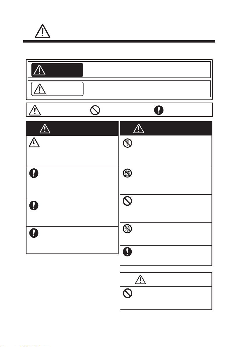
The operator and installer must read the applicable safety instructions before attempting to operate or
install the equipment.
Indicates a potentially hazardous situation which, if not avoided,
could result in death or serious injury.
WARNING
Indicates a potentially hazardous situation which, if not avoided,
can result in minor or moderate injury.
CAUTION
Warning, Caution
Prohibitive Action
Mandatory Action
CAUTION
Do not open the equipment.
This equipment uses high voltage
electricity which can shock, burn or
cause serious injury. Only qualified
personnel can work inside the equipment.
WARNING
If water leaks into the equipment or
something is dropped into the
equipment, immediately turn off the
power at the switchboard.
Fire or electrical shock can result.
If the equipment is giving off smoke
or fire, immediately turn off the
power at the switchboard.
Fire or electrical shock can result.
If you feel the equipment is acting
abnormally or giving off strange
noises, immediately turn off the
power at the switchboard and contact
a FURUNO service technician.
Do not disassemble or modify the
equipment.
Fire, electrical shock or serious injury
can occur. If the equipment does not
work properly, contact your dealer.
WARNING
Make sure no rain or water splash
leaks into the equipment.
Fire or electrical shock can result if water
leaks into the equipment.
Do not place liquid-filled containers
on or near the equipment.
Fire or electrical shock can result if a
liquid spills into the equipment.
Do not operate the equipment with
wet hands.
Electrical shock can result.
Use the correct fuse.
Use of the wrong fuse can cause fire or
electrical shock.
Do not touch any part of the antenna
when the equipment is transmitting.
Electrical shock can result.
SAFETY INSTRUCTIONS
SAFETY INSTRUCTIONS
Do not open the equipment unless
totally familiar with electrical circuits.
The equipment uses high voltage that
can cause electrical shock.
WARNING
Turn off the power at the mains
switchboard before beginning the
installation. Post a warning sign near
the switchboard to indicate that
power should not be applied while
the equipment is being installed.
Electrical shock, serious injury or fire
can result if the power is not turned off
or is applied while the equipment is
being installed.
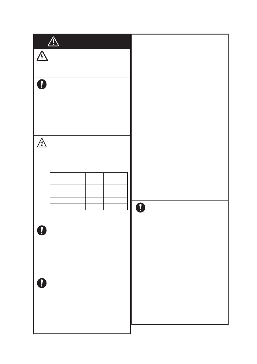
Do not approach the antenna closer
than the distances shown below
when the antenna is transmitting.
The antenna emits radio waves that can
be harmful to the human body.
(MPE: Minimum Permissible Exposure)
100 W/m
2
0.12 m
10 W/m
2
0.39 m
0.2 mW/cm
2
1.50 m
IEC 60945
IEC 60945
MPE by FCC
RF power density
on antenna aperture
Distance
Description
required by
Maximum Antenna Gain: 6dBi
This device complies with part 15 of
the FCC Rules.
Operation is subject to the following
two conditions:
(1) This device may not cause harmful
interference.
(2) This device must accept any interference received, including interference
that may cause undesired operation.
1.2 W/m
2
2.50 m
MPE by IC
This transmitter must not be co-located
or operating in conjunction with any
other antenna or transmitter.
Note: This equipment has been tested
and found to comply with the FCC
standards.
These limits are designed to provide
reasonable protection against harmful
interference in a commercial installation.
This equipment generates uses and can
radiate radio frequency energy and, if
not installed and used in accordance
with the instructions, may cause harmful
interference to radio communications.
However, there is no guarantee that
interference will not occur in a particular
installation.
If this equipment does cause harmful
interference to radio or television
reception, which can be determined by
turning the equipment off and on, the
user is encouraged to try to correct the
interference by one or more of the
following measures:
- Reorient or relocate the receiving
antenna.
- Increase the separation between the
equipment and receiver.
- Connect the equipment into an outlet
on a circuit different from that to which
the receiver is connected.
- Consult the dealer or an experienced
radio/TV technician for help.
[Radiation Exposure Statement]
This equipment complies with FCC
radiation exposure limits set forth for
an uncontrolled environment.
This equipment complies with FCC
radiation exposure limits set forth for an
uncontrolled environment.
This antenna should be installed with
minimum distance 150cm from your
body.
ISEDC RSS warning
This device complies with Innovation,
Science and Economic Development
Canada Compliance RSS standard
(s). Operation is subject to the following
two conditions: (1) this device may not
cause interference, and (2) this
device must accept any interference,
including interference that may cause
undesired operation of the device.
Le présent appareil est conforme aux
CNR d'Innovation, Sciences et Développement économique Canada
applicables aux appareils radio.
L'exploitation est autorisée aux deux
conditions suivantes:
(1) l'appareil ne doit pas produire de
brouillage, et
(2) l'utilisateur de l'appareil doit accepter
tout brouillage radioélectrique subi,
même si le brouillage est
susceptible d'en compromettre le
fonctionnement.
SAFETY INSTRUCTIONS
Confirm that the power supply
voltageis compatible with the voltage
rating of the equipment.
Connection to the wrong power supply
can cause fire or damage the equipment.
CAUTION
WARNING
ISEDC Radiation Exposure Statement:
This equipment complies with ISEDC
RF radiation exposure limits set forth for
an uncontrolled environment.
The antenna should be installed with
minimum distance 250cm from your
body.
This transmitter must not be co-located
or operating in conjunction with any
other antenna or transmitter.
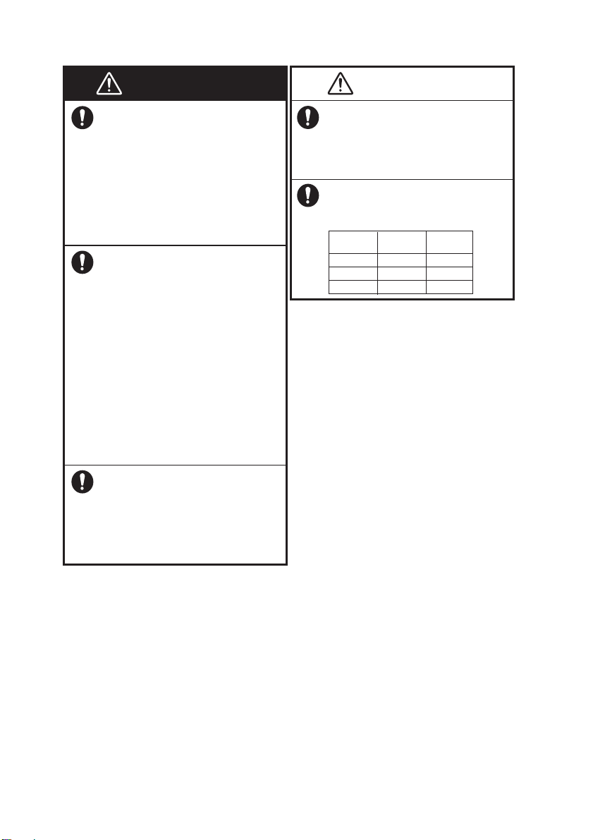
Observe the following safe compass
distances to prevent interference to a
magneticcompass:
Standard
compass
Steering
compass
0.65 m 0.40 m
FM-4800
0.70 m 0.45 m
HS-4800
2.65 m 1.75 m
SP-4800
ISEDC exposition aux radiations:
Cet équipement est conforme avec
ISEDC les limites d'exposition aux
rayonnements définies pour un contrôlé
environnement.
L'antenne doit être installée avec une
distance minimale de 250cm de votre
corps.
Cet émetteur ne doit pas être
co-localisés ou fonctionner en conjonction avec une autre antenne ou
émetteur.
Any Changes or modifications not
expressly approved by the party responsible for compliance could void the
user’s authority to operate the equipment.
CE Compliance Statement
This product complies with CE under
RED directive 2014/53/EU.
The maximum antenna gain is 6dBi,
which is caculated in the EIRP. The
distance form observation point to the
antenna is 2m.

Contents
FOREWORD ................................................................................... 1
SYSTEM CONFIGURATION ........................................................... 2
1.
2.
3.
4.
GETTING STARTED ............................................................ 3
1.1 Emergency Call (CH16) .................................................................................. 3
1.2 How to Call another Channel (CH16 or CH9) .................................................. 3
1.3 Channels 13 and 67 (USA Channel Group only) ............................................. 4
CONTROLS .......................................................................... 5
2.1 Radio ............................................................................................................... 5
2.2 Microphone ..................................................................................................... 6
2.3 Handset ........................................................................................................... 8
HOME SCREEN ................................................................. 10
DIGITAL SELECTIVE CALLING ........................................ 12
4.1 General ......................................................................................................... 12
4.2 Maritime Mobile Service Identity ................................................................... 12
4.2.1 What Is an MMSI? ............................................................................... 12
4.2.2 How to Enter Your MMSI Number ....................................................... 12
4.3 DSC Distress Call.......................................................................................... 13
4.3.1 How to Initiate a DSC Distress Call ..................................................... 13
4.3.2 How to Receive a DSC Distress Call .................................................. 17
4.4 Individual Call ................................................................................................ 17
4.4.1 How to Initiate an Individual Call ......................................................... 18
4.4.2 How to Receive an Individual Call ....................................................... 21
4.5 Group Call ..................................................................................................... 24
4.5.1 How to Initiate a Group Call ................................................................ 24
4.5.2 How to Receive a Group Call .............................................................. 28
4.6 All Ships Call ................................................................................................. 29
4.6.1 How to Initiate an All Ships Call........................................................... 30
4.6.2 How to Receive an All Ships Call ........................................................ 31
4.7 Position Request Call .................................................................................... 32
4.7.1 How to Initiate a Position Request Call ............................................... 32
4.7.2 How to Receive a Position Request Call ............................................. 37
4.8 Auto Position Polling ..................................................................................... 38
4.8.1 How to Enable the Auto Position Polling ............................................. 38
4.8.2 How to Select Vessels to Which the Radio Sends Auto Position Request
Calls ............................................................................................................. 39
4.8.3 How to Monitor Position ...................................................................... 40
4.9 DSC Log ........................................................................................................ 41
4.10 DSC Test ..................................................................................................... 42
i

5.
6.
7.
8.
9.
CHANNEL WATCH ............................................................ 47
5.1 Dual Channel ................................................................................................ 47
5.2 Triple Channel ............................................................................................... 47
SCAN .................................................................................. 49
6.1 Scan All ......................................................................................................... 49
6.2 Scan All + 16 ................................................................................................. 49
6.3 Memory Scan ................................................................................................ 49
6.4 Memory Scan + 16 ........................................................................................ 50
6.5 Editing Memory Channel List ........................................................................ 50
Weather Mode .................................................................... 53
Fog Horn/Hailer/Intercom ................................................. 55
8.1 Fog Horn ....................................................................................................... 55
8.2 Hailer ............................................................................................................. 59
8.3 Intercom ........................................................................................................ 60
8.4 Edit Handset Name ....................................................................................... 61
SETTING MMSI .................................................................. 63
10. GENERAL SETUP .............................................................. 64
10.1 Display Setup .............................................................................................. 64
10.1.1 Adjusting the Backlight ...................................................................... 64
10.1.2 Adjusting the Contrast ....................................................................... 64
10.2 Units ............................................................................................................ 65
10.2.1 Time Form at ...................................................................................... 65
10.2.2 Time Offset ........................................................................................ 65
10.2.3 Speed ................................................................................................ 66
10.2.4 Bearing .............................................................................................. 67
10.3 Key Beep ..................................................................................................... 68
10.4 GNSS Setup ................................................................................................ 68
10.4.1 Entering the "GNSS SETUP" Interface ............................................. 68
10.4.2 Internal GNSS ................................................................................... 68
10.4.3 COG/SOG Display ............................................................................ 69
10.4.4 Manual Position ................................................................................. 69
10.5 I/O Port Setup ............................................................................................. 70
10.5.1 Entering the "I/O PORT SETUP" Interface ........................................ 70
10.5.2 Selecting Output Port ........................................................................ 70
10.5.3 GNSS OUTPUT ................................................................................ 71
10.5.4 DSC OUTPUT ................................................................................... 71
10.5.5 AIS OUTPUT ..................................................................................... 72
10.6 System Information ..................................................................................... 72
10.6.1 Entering the "SYSTEM INFO" Interfac e ............................................ 72
10.6.2 Software Version ............................................................................... 73
10.6.3 Diagnostic Test .................................................................................. 74
10.6.4 Factory Reset .................................................................................... 75
10.7 Fog Horn Frequency ................................................................................... 75
ii

10.8 Service Menu .............................................................................................. 76
11. CHANNEL FUNCTION SETUP ........................................... 77
11.1 Channel Group ............................................................................................ 77
11.2 Second Priority Channel .............................................................................. 77
11.3 Edit Channel Name ..................................................................................... 78
11.4 Private Channel ........................................................................................... 79
12. DSC SETUP ........................................................................ 80
12.1 Individual Directory ...................................................................................... 80
12.1.1 Adding an Entry ................................................................................. 80
12.1.2 Editing an Entry ................................................................................. 81
12.1.3 Deleting an Entry ............................................................................... 82
12.2 Group Directory ........................................................................................... 83
12.2.1 Adding an Entry ................................................................................. 83
12.2.2 Editing an Entry ................................................................................. 84
12.2.3 Deleting an Entry ............................................................................... 85
12.3 Channel Change Mode ............................................................................... 85
12.4 Individual Acknowledgement ....................................................................... 86
12.5 Position Acknowledgement ......................................................................... 86
12.6 Test Acknowledgement ............................................................................... 87
12.7 Auto Position Interval .................................................................................. 87
12.8 Timeout ....................................................................................................... 88
13. ATIS SETUP ....................................................................... 89
13.1 How to Enter the ATIS ID ............................................................................ 89
13.2 How to Enable/Disable the ATIS Feature .................................................... 89
14. MAINTENANCE AND TROUBLESHOOTING .................... 91
14.1 General Maintenance .................................................................................. 91
14.2 Troubleshooting .......................................................................................... 92
15. INSTALLATION .................................................................. 94
15.1 Equipment Lists ........................................................................................... 94
15.2 Mounting ..................................................................................................... 96
15.2.1 How to Install the Radio .................................................................... 96
15.2.2 How to Install the Microphone ........................................................... 98
15.2.3 How to Install the Handset (Optional) ................................................ 98
15.2.4 How to Install the Speaker (Optional) ................................................ 99
15.3 Soft Cover ................................................................................................. 101
15.4 Wiring ........................................................................................................ 101
15.4.1 Overview ......................................................................................... 101
15.4.2 Antenna ........................................................................................... 102
15.4.3 Ground Cable .................................................................................. 104
15.4.4 Power Cable.................................................................................... 104
15.4.5 NMEA2000 Connector (CAN bus connector)
.................................. 106
iii

15.4.6 Extension Cable (Optional) ............................................................. 106
CHANNEL ASSIGNMENTS ........................................................ 108
MENU TREE ............................................................................... 116
SPECIFICATIONS ...................................................................... 119
PACKING LIST ........................................................................... 121
OUTLINE DRAWINGS ................................................................ 125
INTERCONNECTION .................................................................. 132
TOOLS ........................................................................................ 133
iv

FOREWORD
A Word to the Owner of t he FM-4800
FURUNO Electric Company thanks you for purchasing the FM-4800 Marine VHF
Radiotelephone. We are confident you will discover why the FURUNO name has
become synonymous with quality and reliability.
Since 1948, FURUNO has enjoyed an enviable reputation for quality and reliability
throughout the world. This dedication to excellence is furthered by our extensive
global network of agents and dealers.
Your equipment is designed and constructed to meet the rigorous demands of the
marine environment. However, no machine can perform its intended function unless
properly installed and maintained. Please carefully read and follow the operation,
installation and maintenance procedures set forth in this manual.
We would appreciate feedback from you, the end-user, about whether we are
achieving our purposes.
Thank you for considering and purchasing FURUNO.
Features
FURUNO FM-4800 Marine VHF Radiotelephone supports the following features:
All-in-One Marine VHF Radiotelephone
25 W or 1 W RF Output Power
Class D DSC with Distress, Individual and All Ship calls
Built-in AIS receiver
Built-in high-sensitivity GNSS receiver
30 W PA/Loud Hailer with automatic fog signals and listen back
NMEA2000 & NMEA0183 interface
Dual station with optional handset HS-4800
ATIS mode available for inland waterway in Europe
Pre-programmed frequency band for USA, Canadian and International marine
channels, plus 10 weather channels where available
Initiate DSC call directly from NavNet TZtouch2 series when connected
(Version 1950152-06.01 or later)
Fully-waterproofed transceiver, microphone and handset (IP67)
Quick access to channel 16/9
Display GNSS Navigation information (LAT/LON, SOG, COG)
Program No.: FM-4800 : 0550257-01.**; HS-4800 : 0550259-01.**. (** denotes
minor modifications.)
1
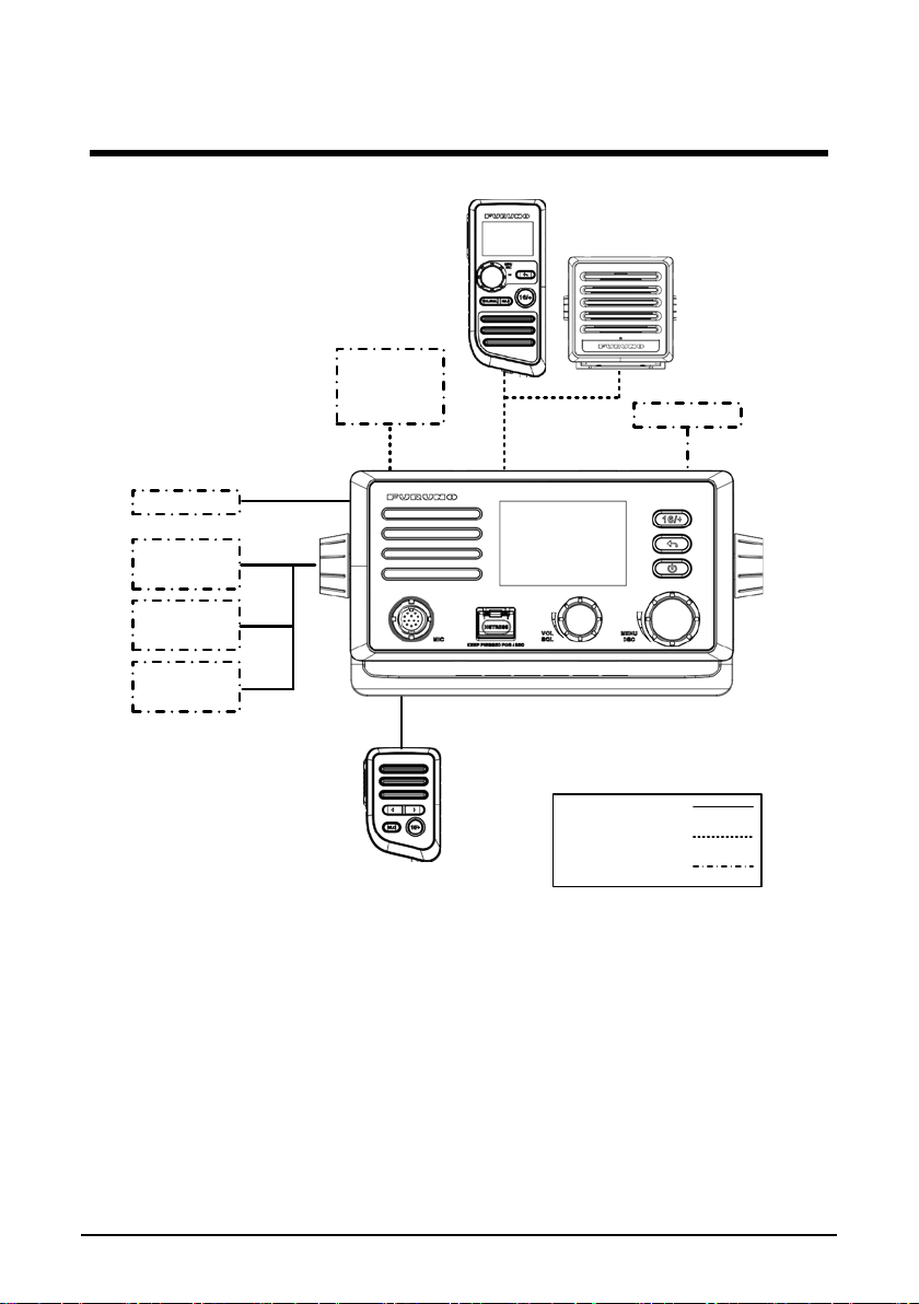
SYSTEM CONFIGURATION
12VDC
External
Speaker
Horn
Speaker
NAV
EQUIPMENT
NMEA0183
MICROPHONE
MIC-4800
HANDSET
HS-4800
Navnet
Tztouch/2
NMEA2000
EXTENSION
CABLE
MARINE VHF
RADIOTELEPHONE
FM-4800
Standard Supply
Optional Supply
Local Supply
SPEAKER
SP-4800
VHF ANT
2

1. GETTING STARTED
1.1 Emergency Call (CH16)
CH16 is known as the Hail and Distress Channel. When an emergency occurs, be
sure the radio is on and set to CH16. Then do as follows:
Step 1 Press the Push-To-Talk (PTT) key of the microph one or handset and say
Step 2 Then repeat once: "Mayday, XXXXX" (your vessel's name).
Step 3 Report your position in latitude/longitude, or give a true or ma gneti c
Step 4 Report the nature of your distress (sinking, collision, aground, fire, piracy,
Step 5 State the kind of assistance you desire (pumps, medical aid, etc.).
Step 6 Report the number of persons aboard and condition of them.
Step 7 Estimate the present seaworthiness and condition of your vessel.
Step 8 Give your vessel's description: length, design (power or sail), color and
Step 9 Say "over" to end the message. Release the PTT switch and listen.
Step 10 Optional: If there is no answer, repeat the above procedure. If there is still
"Mayday, Mayday, Mayday. This is XXXXX, XXXXX, XXXXX" (your
vessel's name).
bearing to a well-known landmark such as a navigation aid or geographic
feature such as an island or harbor entry.
life-threatening injury, etc.).
other distinguishing marks.
no response, try another channel.
Note
The total transmission should be within one minute.
The FM-4800 has DSC Distress calling, which can se nd a distres s call
digitally to all ships with compatible DSC radios. For more information, see
section 4 DIGITAL SELECTIVE CALLING.
If the eme rgency call is accidentally sent, please refer to "Sending a d istress
cancel call" in paragraph 4.3.1.
1.2 How to Call another Channel (CH16 or CH9 )
CH16 (or CH9, depending on area) should be used as the calling chan nel for initial
contact with another vessel. However, its primary purpose is for emergency
communications and should be monitored at all times when the radio is not using
other channels.
CH16 or CH9 is monitored by other vessels and Coast Guard stations in all
countries.
The use of CH16 or CH9 should be limited to making initial contact only. A call
3

should be within 1 minute, but can be repeated at a 2-minute interv al.
Before contact anot her v ess el, r efer to the channel charts in the Appen dix and select
a proper channel (w orking c ha nnel) for use after initial contact. M onitor th e pr oposed
channel to ensure you w on' t b e interrupting other traffic an d t hen g o back to CH16 to
make your initial call.
When CH16 is clear, state the name of the vessel you wish to call and the "this is"
followed by the name of your vess el and y our v essel call sign . When the other vessel
returns your call, immediately request another channel by saying "go to", the
number of the other channel, and "over". Then switch to the new channel. When the
new channel is not busy, call the vessel.
After a transmission, say "over", and release the PTT switch on the microphone.
When all communication with the vessel is completed, end the last transmission by
stating your call sign an d the word "out". Note that you do not need to state your call
sign with each transmission, only at the beginning and end of the contact.
Remember to return to CH16 when not using another channel. Some radios
automatically monitor CH16 even when set to other channels or when scanning.
1.3 Channels 13 and 67 (USA Channel Group only)
Channel 13 is used at docks and bridges and by vessels maneuvering in port.
Messages on this channel must concern navigation only, such as meeting and
passing in restricted waters.
Channel 67 is used for navigational traffic between vessels.
By regulation, power is normally limited to 1 Watt on these channels. Your radio is
programmed to automatical ly reduc e pow er to thi s limit o n these c hannel s. How ever,
in emergency situations it may be temporarily use a higher power. See section 2
CONTROLS for how to temporarily override the low-power limit on these two
channels.
4
5
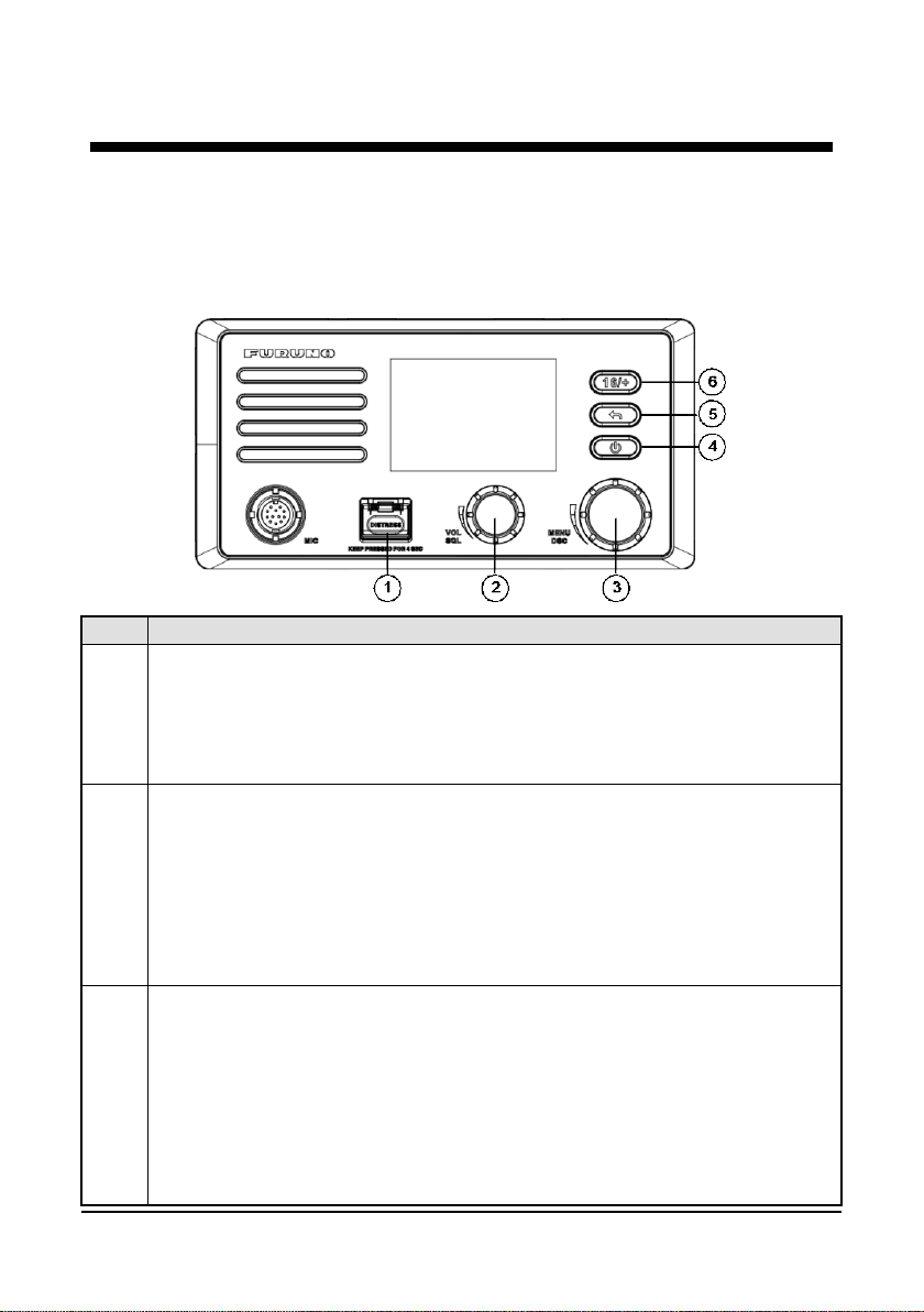
No.
Description
[DISTRESS]: Distress Key
[VOL/SQL]: Volume / Squelch Control
[MENU/DSC]: Menu / Digital Selective Calling (DSC) Control
2. CONTROLS
This section de scribes the controls of the radio FM-4800, the microphone MIC-4800,
the handset HS-4800.
2.1 Radio
Short press: Enter the distress nature selection and position manual
1
input menu
Long press: Press the DISTRESS key for 4 seconds to send a distress
call.
Press: Switch between the volume adjust screen and the squelch adjust
screen
2
Rotate
On "SQUELCH" or "VOLUME" screen: Adjust the squelch or volume
level
On other screens: Adjust the volume
On the home screen:
Press: Enter "MAIN ME N U"
3
On other screens:
Rotate: Switch to a channel
Press: Select item or confirm the sele ctio n
Rotate: Move to other item or select a number

6
No.
Description
[ ]: On / Off Key
[ ]: Back Key
entries, cancel calls, b ac ksp ac e the cursor, or back
Long press: Return to the home screen
[16/+]: 16/+ Key
Press the key to cancel all other modes and to tune into the priority channels
eturn to the previously selected
CH16.
4
Short press: Enter the display setup mode
Long press: Power on or power off
On the home screen: No function
5
6
On other screens:
Short press: Clear
up to the previous screen
(CH16 and CH9). Press the key again to r
working channel.
Note
CH9 is used in some parts of the world as an alternative hailing channel to
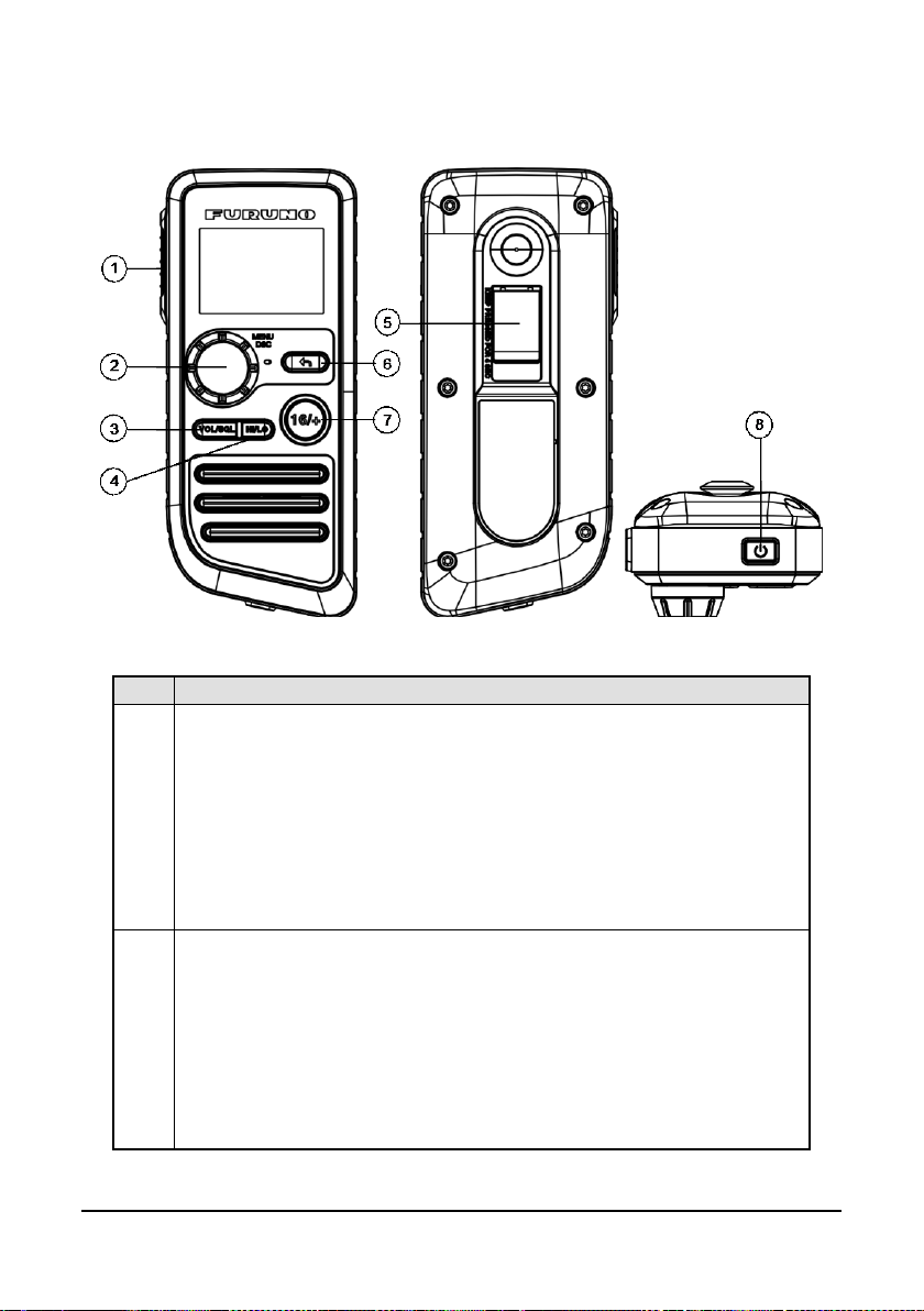
2.2 Microphone

7
No.
Description
[PTT]: Push-to-Talk Key
radio mode to enable the radio for voice
When the PTT key on the microphone is pressed continuously, transmission
tomatically reduced to protect against overheating
due to continuous transmission .
[ ]: Cursor Key
[HI/LO]: High / Low Power Switch
Press the switch to toggle between 25 W (High) and 1 W (Low)
[16/+]: 16/+ Key
the key to cancel all other modes and to tune into the priority channels
(CH16 and CH9). Press the key again to return to the previously selected
an alternative calling channel to
CH16.
Press and hold the key in
communication.
Note:
1
time is limited to five minutes. This limits unintentional transmissions due to a
stuck PTT key.
In addition, Power is au
2
3
4
Changes the channel up or down.
Press
working channel.
Note
CH9 is used in some parts of the world as
8
No.
Description
The transmitter is enabled for voice communications with another
When the PTT key on the microphone is pressed continuously,
five minutes. This limits unintentional
In addition, Power is automatically reduced to protect against
overheating due to continuous transmission.
[MENU/DSC]: Menu / Digital Selective Calling (DSC) Control
2.3 Handset
[PTT]: Push-to-Talk Key
vessel.
Note:
1
transmis sion time is limited to
transmissions due to a stuck PTT key.
On the home screen:
Press: Enter "MAIN ME N U"
2
Rotate: Switch to a channel
On other screens:
Press: Select item or confirm the selection
Rotate: Move to other item or select a number
9
No.
Description
[VOL/SQL]: Volume / Squelch Control
volume adjust screen and the
squelch adjust screen.
[HI/LO]: High / Low Power Switch
Press the switch to toggle between 25 W (High) and 1 W (Low).
[DISTRESS]: Distress Key
[ ]: Back Key
Long press: Return to the home screen
[16/+]: 16/+ Key
Press the key to cancel all other modes and to tune into the priority
channels (CH16 and CH9). Press the key again to return to the
an alternative calling
channel to CH16.
[ ]: On / Off Key
Press the key to turn the handset on or off.
3
Press the key to switch between the
4
Short press: Enter the distress nature selection and position
5
manual input menu
Long press: Press the DISTRESS key for 4 seconds to send a
distress call.
On the home screen: No function
On other screens:
6
7
Short press: Clear entries, cancel calls, backspace the cursor,
or back up to the previous screen
previously selected working channel.
Note
CH9 is used in some parts of the world as
8
10
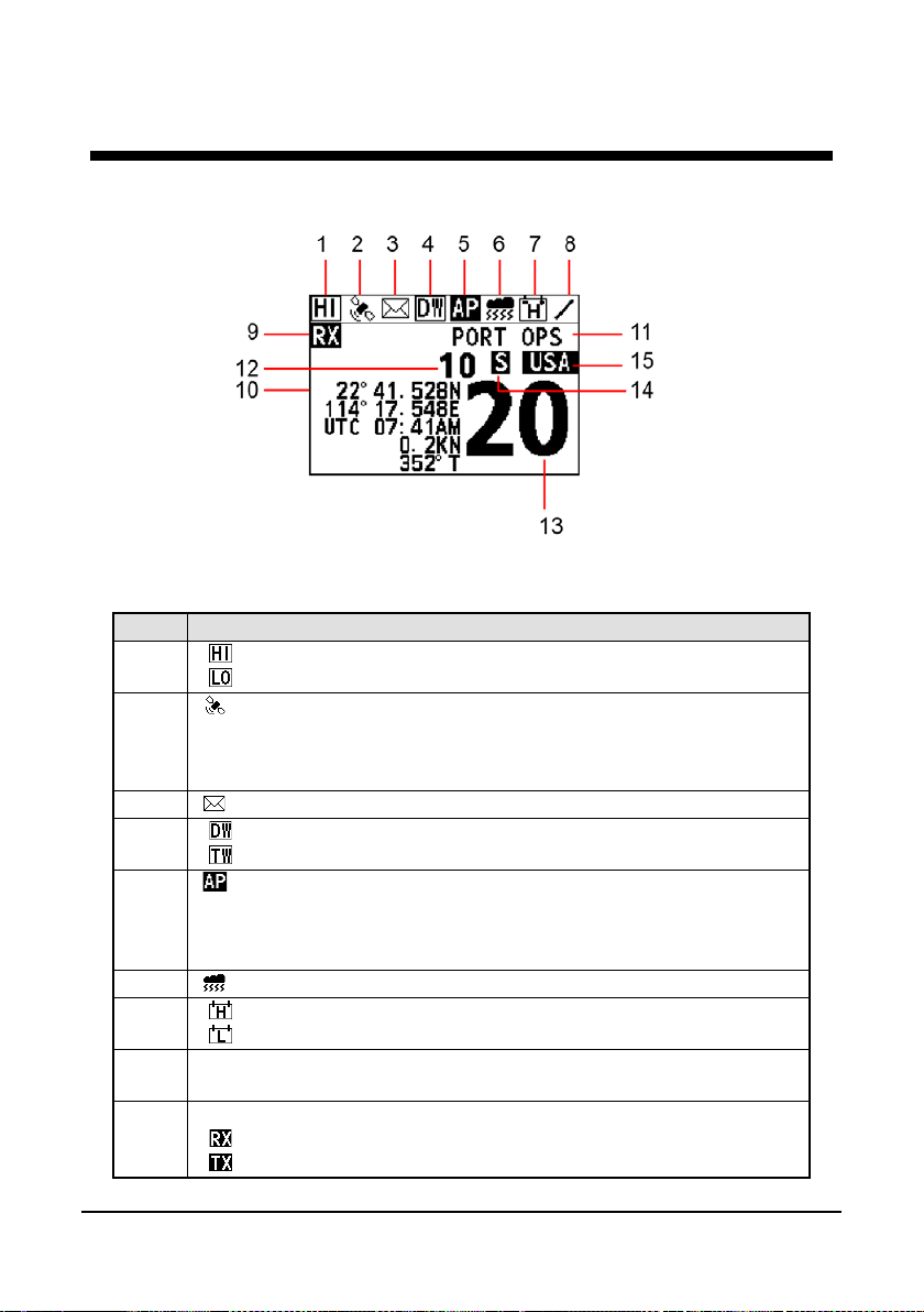
No.
Description
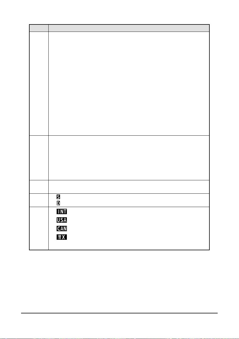
- : indicates high power such as 25 W.
- : indicates low power such as 1 W.
: indicates internal and External GNSS.
current internal GNSS and External GNSS are not fixed.
3
: indicates unread DSC messages.
- : indicates the dual watch mode.
- : indicates the triple watch mode.
: This icon appears if user selects START of AUTO POS
POLLING->ACTIVATION.
6
: indicates weather alert.
- : indicates battery strength more than 15.6V.
- : indicates battery strength lean than 10.5V.
Operational Status icon
(Rotates clockwise to indicate system is working)
-No icon:FM standby.
-
Indicates transmission.
3. HOME SCREEN
1
2
4
5
7
8
9
This icon disappears if there is no GNSS data.
This icon f lashes with 500ms when there is GNSS data before, but
POLLING->ACTIVATION.
This icon disappears if user selects END of AUTO POS
- :Indicates reception.
:
11
No.
Description
Display location information including longitude, latitude, time, COG,
in sensor: The GNSS data from this sensor enjoys the
and NMEA2000, the GNSS data from NMEA2000 will be used.
In non scan mode: display CH NAME.
SCAN+16
12 &
13
Displays the current channel number.
Note: the channel number 12 is not displayed.
- :Indicates that the current channel is si mplex.
- :Indicates that the current channel is duplex.
WEATHER MODE is ON.
and SOG.
If there is no any information, it displays "NO GNSS DATA".
Note
There are three sensors including built-in sensor, NMEA2000 and
NMEA0183. The last two are external sensors. Their priorities in
10
11
descending order are described as follows:
1. Builthighest priority.
2. NMEA2000: If no valid GNSS data is from the built-in sensor or
this sensor is disabled, the GNSS data from NMEA2000 will be
used.
3. NMEA0183: If no valid GNSS data from both the build-in sensor
In scan mode:
SCAN ALL: indicates that the user selects SCAN ALL
SCAN ALL+16: indicates that the user selects SCAN ALL+16
MEMORY SCAN: indicates that the user selects MEMOR Y S C AN
MEMORY SCAN +16: indicates that the user selects MEMORY
14
- : This icon appears if CH GROUP is INT.
- : This icon appears if CH GROUP is USA
15
- : This icon appears if CH GROUP is CAN
- : This icon appears if CH GROUP is USA or CAN, and
12
4. DIGITAL SELECTIVE CALLING
4.1 General
Digital Selective Calling (DSC) is a semi-automated method to establish a radio call.
DSC has been designated by the International Maritime Organization (IMO) as an
international standard for establishing VHF, MF and HF radio calls. It has also been
designated as a part of the Global Maritime Distress and Safety System (GMDSS).
DSC replaces listening watches on distress frequencies and is used to broadcast
routine and urgent maritime safety information broadcasts.
This system allows mariners to instantly transmit a distress call with GNSS position
to the Coast Guard and other vessels within the range of the transmission. DSC also
allows mariners to initiate or receive distress, urgency, safety, routine, position
request, position transmit, and group calls to or from another vessel equipped with a
DSC radio.
4.2 Maritime Mobile Service Identity
4.2.1
An MMSI is a nine-digit number used on marine radios capable of using DSC. This
number is used like a telephone number to selectively call other vessels.
What Is an MMSI?
Note
To use the DSC functions, this vessel’s MMSI must be entered into the radio.
4.2.2 How to Enter Your MMSI Number
Caution
An MMSI can be entered only once. Therefore, be careful not to enter the wrong
MMSI number . If you need to change the MMSI number after it has been entered,
contact your dealer.
Step 1 Press the Menu/DSC control until the "MAIN MENU" appears.
Step 2 Go to "DSC SETUP > SET MMSI".
Step 3 Enter you MMSI number (nine digits).
If you enter a wrong digit, press the BACK key until the wrong digit is
selected, and then enter the correct dig it.
Step 4 After you enter the MMSI number, press the Menu/DSC control to save
the number.
Step 5 Enter the MMSI number again, and then press the Menu/DSC control to
save the number.
13
4.3 DSC Distress Call
FM-4800 can send and receive DSC distress calls. When FM-4800 receives GNSS
signals, FM-4800 can also transmit the latitude and longitude of the vessel together
with the DSC distress call.
4.3.1 How to Initiate a DSC Distress Call
Note
To transmit a DSC distress call, this vessel’s MMSI number must be entered into
the radio. For information about how to enter the MMSI number, see section
4.2.2 How to Enter Your MMSI Number.
Initiate a DSC distress call without specifying the nature of distress
The FM-4800 can transmit a DSC distress call without specifying the following
natural of distress categori es: U ndes igna ted, Fir e, Floodi ng, C olli sio n, Groun din g,
Listing, Sinking, Adrift, Abandoning, Piracy, and MOB (Man Overboard).
Step 1 Open the cover labeled "DISTRESS".
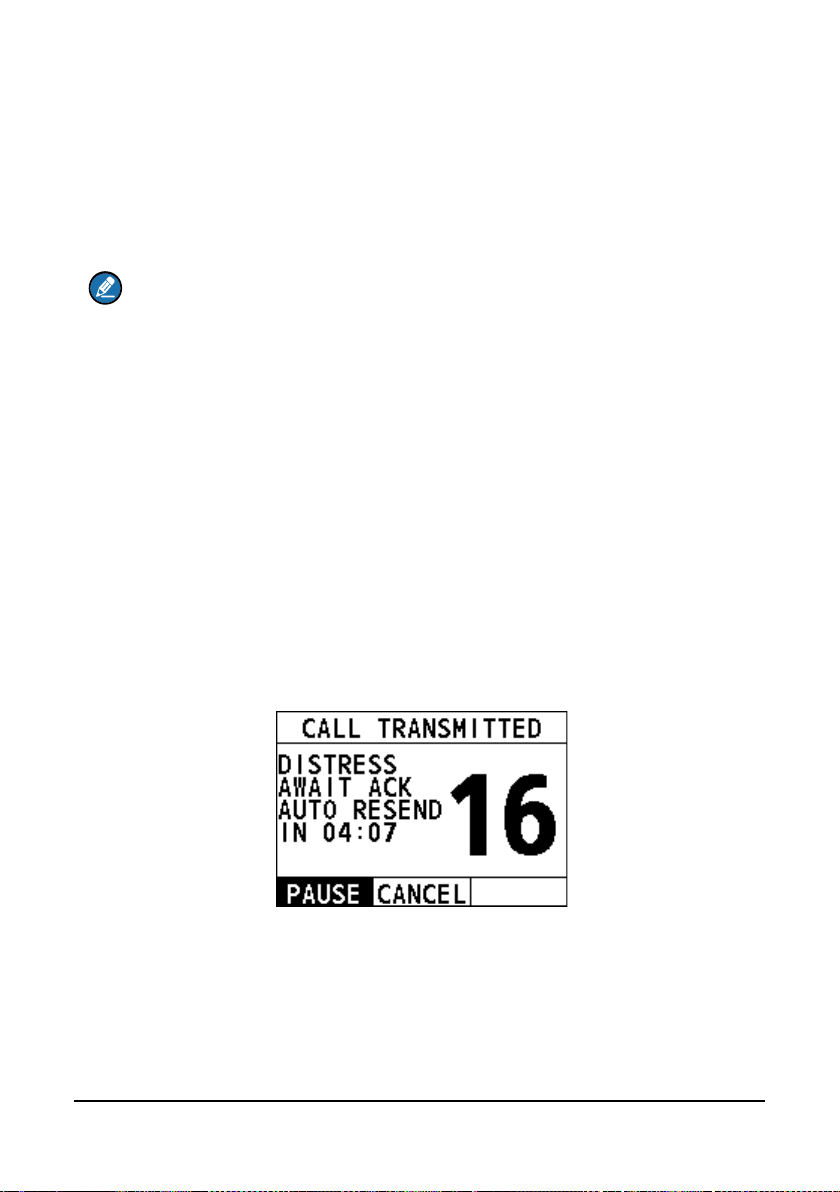
Step 2 Press and hold the Distress key (about 4 seconds). The unit beeps and
the display shows the time remaining until the distress signal is sent.
After the distress signal is sent, the radio waits for an acknowledgement with the
display showing "AWAIT ACK".
If no acknowledgement is r eceived, the distress signal is repeated at
3.5-to-4.5-minute in tervals, until a DSC acknowledgement is received.
Step 3 When you receive the DSC acknowledgement, select "ACCEPT".
If the radio does not stay on CH16, you need to select "Accept".
14
If the radio already stays on CH16, skip this step.
Step 4 Press and hold the PTT key to announce your situation on CH16.
Initiate a DSC distress call with the nature of distress specified
The FM-4800 is capable of transmitting a DSC distress call with the followi ng
distress categories: Undesign ated, Fire, Flo odin g, Co lli sio n, G roundin g, Listing,
Sinking, Adrift, Abandoning, Piracy, and MOB (Man Overboard).
Step 1 Open the cover labeled "DISTRESS".
Step 2 Short-press the Distress key.
The "DISTRESS" screen appears.
Step 3 Select "NA TURE".
The "NATURE" screen appears.
Step 4 Select the nature of the distress.
Step 5 Press and hold the Distress key (about 4 seconds). The unit beeps and
Step 6 When you receive the DSC acknowledgement, select "ACCEPT".
Step 7 Press and hold the PTT key to announce your situation on CH16.
the display shows the time remaining until the distress signal is sent.
After the distress signal is sent, the radio waits for an acknowledgement with the
display showing "AWAIT ACK".
If no acknowledgement is r eceived, the distress signal is repeated at
3.5-to-4.5-minute intervals, until a DSC acknowledgement is r eceived.

15
Initiate a DSC distress call with manually inputted position
If no position data is available at the time of distress, you can enter the latitude and
longitude position of your vessel manually when you send a DSC distress call.
Step 1 Open the cover labeled "DISTRESS".
Step 2 Short-press the Distress key.
The "DISTRESS" screen appears.
Step 3 Select "POS".
Step 4 Rotate and press the Menu/DSC control to enter the latitude and longitude
Step 5 Press and hold the Distress key (about 4 seconds). The unit beeps and
of your vessel and current UTC time in 24-hour format.
the display shows the time remaining until the distress signal is sent.
After the distress signal is sent, the radio waits for an
acknowledgement with the display showing "AWAIT ACK".
If no acknowledgement is received, the distress signal is repeated at
3.5-to-4.5-minute intervals, until a DSC acknowledgement is
received.
Step 6 When you receive the DSC acknowledgement, select "ACCEPT".
Step 7 Press and hold the PTT key to announce your situation on CH16.
Pause a DSC distress call
After a DSC distress call is sent, the DSC distress call is repeated at
3.5-to-4.5-minute intervals until the call is canceled by the user, until an
acknowledgement is received, or until the radio is turned off. T he FM -4800 has a
provision to pause the retrans mitt ing of the distress call. To pause the distress call,
select "PAUSE".
Restart the DSC distress call
After you select “PAUSE”, the but ton is sw itche d t o "RE SU ME ". At t h is t im e, y ou c an
select "RESUME" to restart the DSC distress call.
Sending a distress cancel call
When the emergency is released, you can cancel the distress call.
Step 1 On the "CALL TRANSMITTED" interface, select "CANCEL".
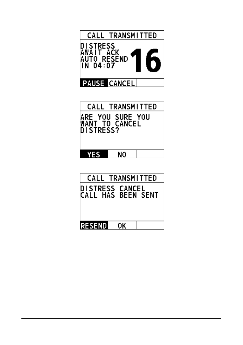
16
Step 2 Select "YES".
Step 3 Select "OK".
Step 4 Press and hold the PTT key to announce your situation.
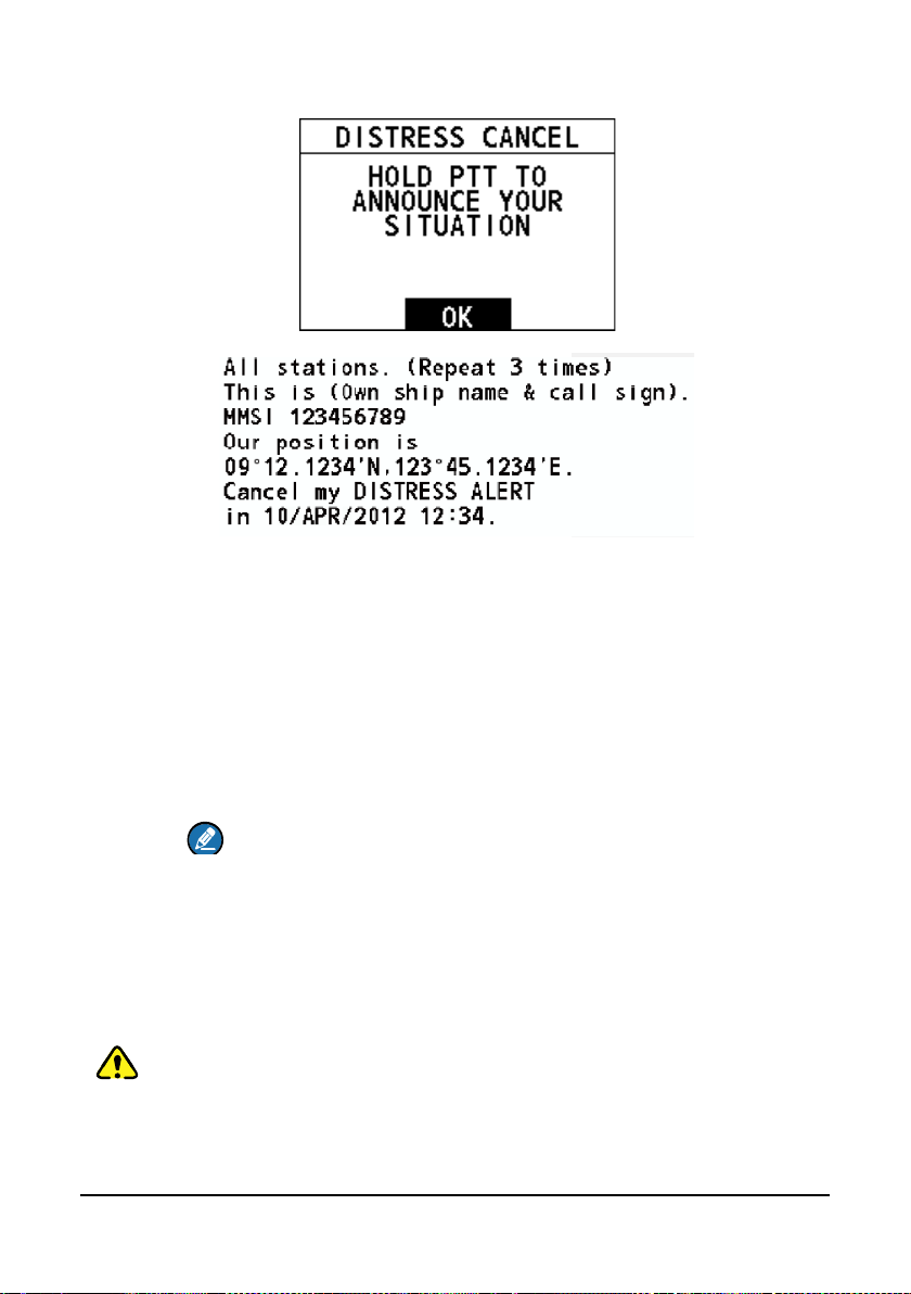
17
Step 5 Select "OK" to return to the home screen.
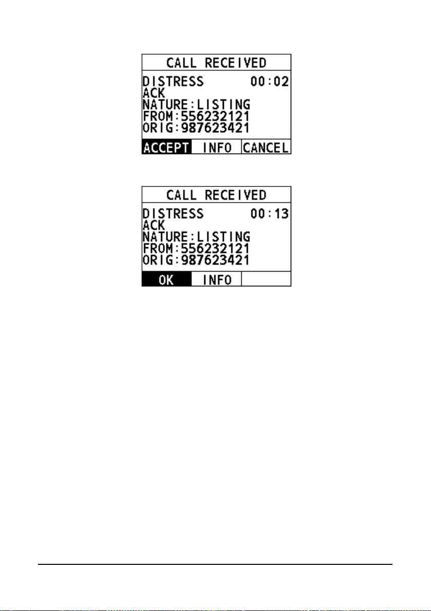
4.3.2 How to Receive a DSC Distress Call
Step 1 When a DSC distress call is received, the emergency alarm sounds.
Step 2 Optional: The display shows the MMSI of the vessel in distress. To show
Step 3
Rotate the Menu/DSC control to stop the alarm.
additional information of the vessel in distress, select "INFO", and then
select "OK".
To accept the distress call, select "ACCEPT".
The radio switches to CH16 automatically.
Note
If you press "CANCEL", the radio quits the automatic switching to
CH16 and reverts to the last selected working channel.
Step 4 Listen on CH16 for five minutes.
4.4 Individual Call
This feature allows you to contact a vessel with the DSC feature.
Caution
To make a DSC individual call, the radio of the receiving party should be set to
manually acknowledge the individual call request from the initiating party.
Otherwise, the radio of the receiving party will automatically send an "unable to
acknowledge" message and the individual call cannot be established. For
information about how to set it, see 11.4 Individual Acknow ledgement.
18
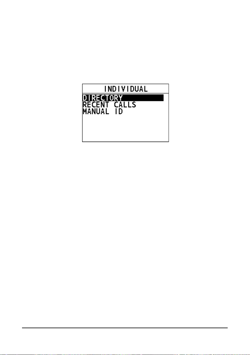
4.4.1 How to Initiate an Individual Call
Enter the individual call interface
Step 1 On the home screen, press the Menu/DSC control to enter the "MAIN
MENU" screen.
Step 2 Go to "DSC CALL > INDIVIDUAL".
The "INDIVIDUAL" interface appears on the screen.
Initiate an individual call to a vessel registered in the individual directory
Before you initiate an individual call from the individual directory, a vessel or
person's name and the MMSI number associated with the vessel you want to
transmit the call should be added to the individual directory. For information about
how to add entries to individual directory, see section 11.1.1 Adding an Entry.
Step 1 On the "INDIVIDUAL" interface, select "DIRECTORY".
Step 2 Select an individual contact, and then press the Menu/DSC control to
Step 3 Select a channel.
Step 4 Press the Menu/DSC control to initiate an individual call.
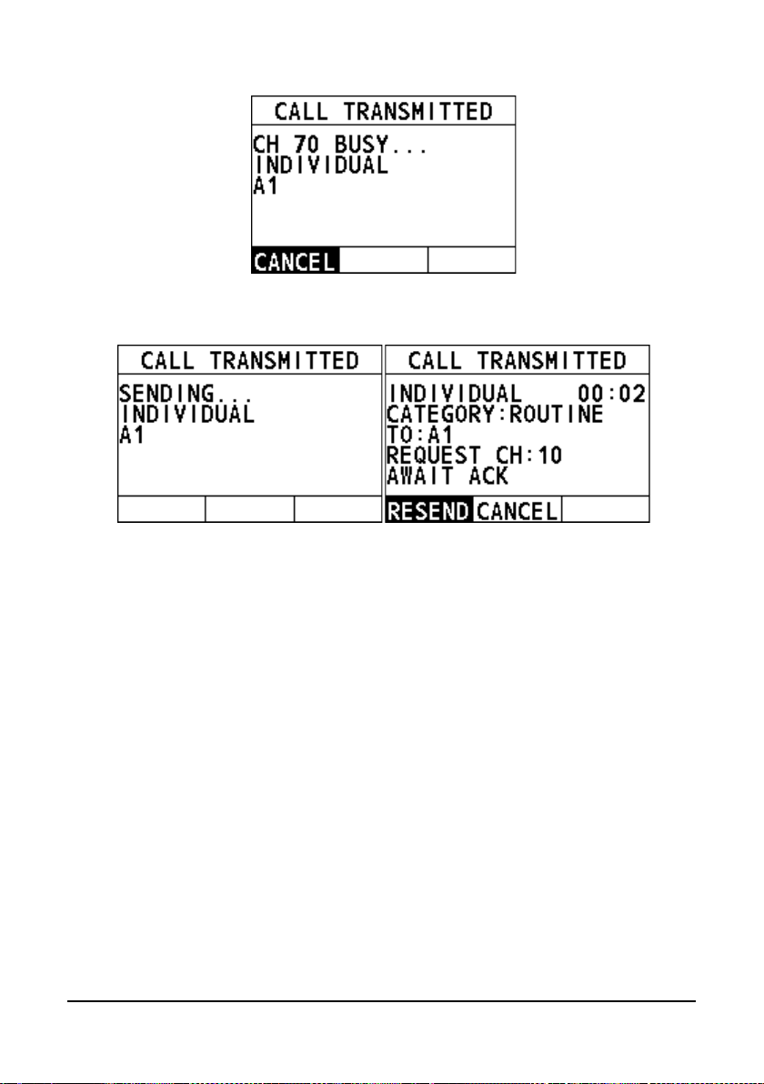
enter the "SELECT CH" interface.
When CH70 is busy, the following screen appears. You can wait
without pressing any key until CH70 is idle.
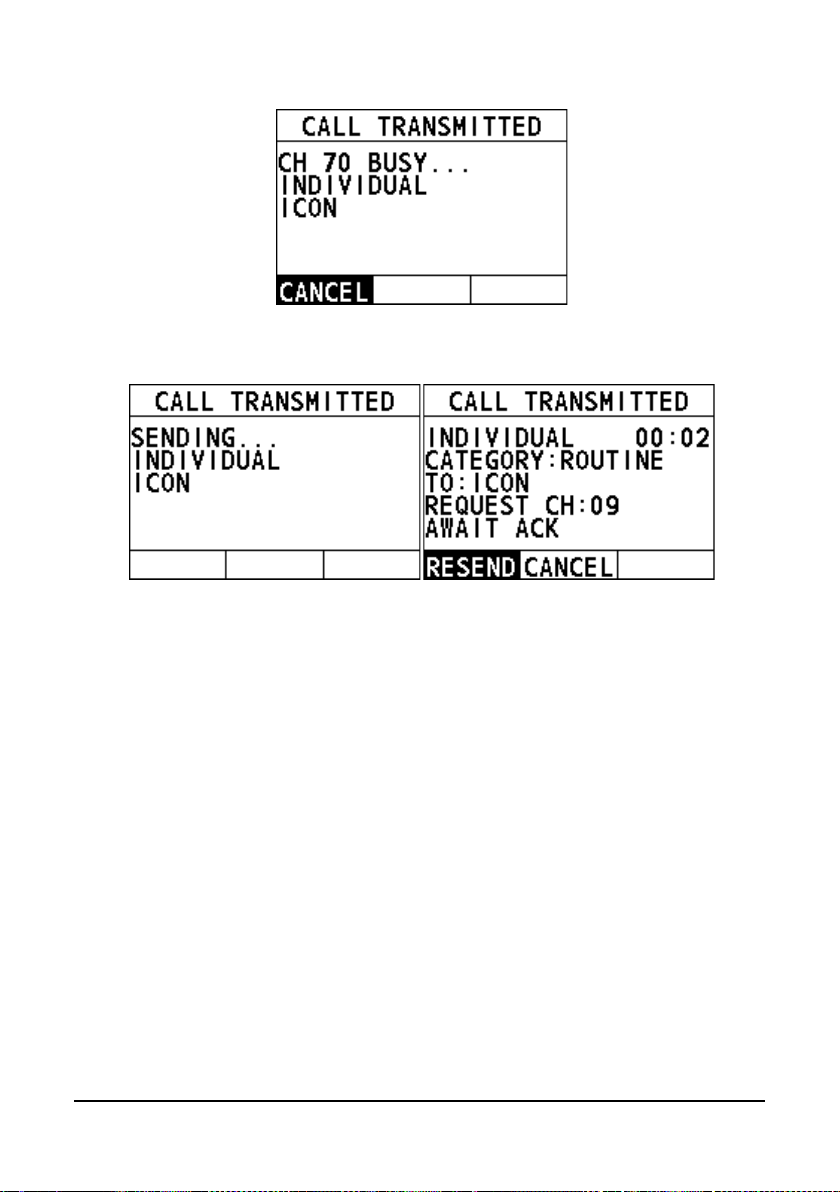
19
When the CH70 is idle, the following screens appear, and the radio
waits for an acknowledgement.
Step 5 When the radio receives an acknowledgement, an alarm sounds and the
Step 6 Press and hold the PTT key to talk into the microphone.
working channel changes to the channel selected in Step 3. Select "OK"
on the screen.
Initiate an individual call from the "RECENT CALLS"
Step 1 On the "INDIVIDUAL" interface, select "RECENT CALLS".
Step 2 Select an individual contact, and then pres s the Menu/DSC control to
Step 3 Select a channel.
Step 4 Press the Menu/DSC control to initiate an individual call.
enter the "SELECT CH" interface.
When CH70 is busy, the following screen appears. You can wait
without pressing any key until CH70 is idle. "A1" indicates the alias of
called party. If the called party has no alias, the MMSI of called party
will appear.
20
When the CH70 is idle, the following screens appear, and the radio
waits for an acknowledgement.
Step 5 When the radio receives an acknowledgement, an alarm sounds and the
working channel changes to the channel selected in Step 3. Select "OK"
on the screen.
Step 6 Press and hold the PTT key to talk into the microphone.
Initiate an individual call by manually entering an MMSI number
Step 1 On the "INDIVIDUAL" interface, select "MANUAL ID".
Step 2 Enter the MMSI of your desired individual conta ct, and then pres s the
Menu/DSC control to enter the "SELECT CH" interface.
Step 3 Select a channel.
Step 4 Press the Menu/DSC control to initiate an individual call.
When CH70 is busy, the following screen appe ars. You can wait
without pressing any key until CH70 is idle.

21
When the CH70 is idle, the following screens appear, and the radio
waits for an acknowledgement.
Step 5 When the radio receives an acknowledgement, an alarm sounds and the
Step 6 Press and hold the PTT key to talk into the microphone.
working channel changes to the channel selected in Step 3. Select "OK"
on the screen.
4.4.2 How to Receive an Individual Call
The channel change of your radio has two modes: "AUTO" and "MANUAL". When
you select "AUTO", the radio automatically switch to th e designated channel after 10
seconds without user intervention. When selecting "MANUAL", you need to
manually change the channel. For information about how to set the channel change
mode, see section 11.3 Channel Change Mode.
When the channel change mode is "AUTO"
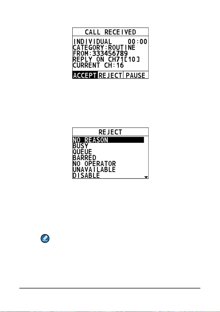
Step 1 When an individual call is received, the alarm sounds. Rotate the
Menu/DSC control to stop the alarm.
The radio screen shows the MMSI of the calling vessel and three soft keys:
"ACCEPT", "REJECT", and "PAUSE". If the requested channel cannot
comply, the screen only shows two soft keys: "REJECT" and "CANCEL".
22
ACCEPT: Select the soft key to continue with the call and switch to the
requested channel.
REJECT: Select the soft key to reject the call. After you select
"REJECT", the following screen appears. Select a reason for rejecting
the call, and then an "UNABLE ACK" message is sent. After the
message is sent, the radio returns to the home screen and the channel
remains unchanged.
PAUSE: Select the soft key to pause the call and timing and temporarily
disable automatic switching to the reque sted ch anne l. You can resume
the call by pressing the "RESUME" soft key.
Step 2 Select "ACCEPT".
When CH70 is busy, you can wait without pressing any key until CH70
is idle.
When CH70 is idle, the radio sends an acknowledgement and the
requested channel is selected, ready for a conversation.
Note
If no key is pressed within 10 seconds, the radio automatically sends an
acknowledgement and switches to the requested channel when CH70 is idle.
Otherwise, the radio will wait until CH70 is idle.
Step 3 Press and hold the PTT key to talk into the microphone.
 Loading...