

Furuno USA 9ZWFM4000 Users Manual
MARINE VHF RADIOTELEPHONE
With Class D DSC Modem and CH70 with receiver
FM-4000
Owner’s Manual
l
Commercial grade ITU class D DSC transceiver
Superior receiver performance (80 dB rejection)
l
30W LoudHailer complete with listen-back and four fog horns, bells, and
l
whistle
2.2-inch internal speaker produces clear, loud audio
l
2.58" x 1.28" dot matrix display
l
Alphanumeric keypad allows direct entry of channel numbers or selection of
l
most used functions
NAV mode displays latitude/longitude, position, time, SOG, COG*
l
Oversized rotary selector, volume and squelch knobs
l
Programmable scan, selectable priority scan, and dual watch
l
One-button access to CH16 and CH9
l
Treble and bass audio tone control
l
Two inputs for optional Remote MIC
l
Optional voice scrambler
l
Multi-station intercom
l
High and low voltage warnings
l
**
When attached to GPS Receiver
Page 1FM-4000

TABLE OF CONTENTS
1 GENERAL INFORMATION ...................................................................................................................... 4
1.1 INTRODUCTION .......................................................................................................................... 4
2 PACKING LIST ......................................................................................................................................... 5
3 OPTIONS ................................................................................................................................................... 5
4. SAFETY/WARNING INFORMATION ....................................................................................................... 5
5 FCC RADIO LICENSE INFORMATION ................................................................................................. 6
5.1 STATION LICENSE ..................................................................................................................... 6
5.2 RADIO CALL SIGN ..................................................................................................................... 6
5.3 CANADIAN SHIP STATION LICENSING .................................................................................... 6
5.4 FCC / INDUSTRY CANADA INFORMATION ............................................................................. 6
6 FCC NOTICE ............................................................................................................................................ 7
7 GETTING STARTED ................................................................................................................................ 8
7.1 ABOUT VHF RADIO ................................................................................................................... 8
7.2 SELECTING AN ANTENNA .......................................................................................................8
7.3 COAXIAL CABLE ........................................................................................................................ 8
8 INSTALLATION ......................................................................................................................................... 9
8.1 LOCATION ................................................................................................................................... 9
8.2 OPTIONAL MMB-84 FLUSH MOUNT INSTALLATION ............................................................ 9
8.3 OPTIONAL CMP30 REMOTE MIC ........................................................................................... 10
8.4 ELECTRICAL CONNECTIONS ................................................................................................. 12
8.5 ACCESSORY CABLE ............................................................................................................... 13
8.6 CHANGING THE TIME INDICATION ...................................................................................... 14
8.7 CHANGING THE COG INDICATION ...................................................................................... 14
9 CONTROLS AND INDICATORS ........................................................................................................... 16
9.1 CONTROLS AND CONNECTIONS.......................................................................................... 16
10 BASIC OPERATION............................................................................................................................... 22
10.1 PROHIBITED COMMUNICATIONS .......................................................................................... 22
10.2 RECEPTION ............................................................................................................................... 22
10.3 TRANSMISSION ........................................................................................................................ 23
10.4 TRANSMIT TIME-OUT TIMER (TOT) ...................................................................................... 23
10.5 SIMPLEX/DUPLEX CHANNEL USE ........................................................................................ 23
10.6 USA, CANADA, AND INTERNATIONAL MODE ...................................................................... 23
10.7 NOAA WEATHER CHANNELS ................................................................................................ 24
10.7.1 NOAA Weather Alert ................................................................................................. 24
10.7.2 NOAA Weather Alert Testing ................................................................................... 24
10.8 EMERGENCY (CH16 USE) ...................................................................................................... 25
10.9 CALLING ANOTHER VESSEL (CH 16 OR CH9) ................................................................... 25
10.10 MAKING TELEPHONE CALLS ................................................................................................ 26
10.11 OPERATING ON CHANNELS 13 AND 67 ............................................................................ 26
10.12 DUAL WATCH (TO CH16) ......................................................................................................... 27
10.13 SCANNING................................................................................................................................. 27
10.13.1 Selecting the Scan Type .......................................................................................... 27
10.13.2 Memory Scanning (M-SCAN) .................................................................................... 27
10.13.3 Priority Scanning (P-SCAN) ...................................................................................... 28
10.14 PA/FOG OPERATION ............................................................................................................... 29
10.14.1 Operating the PA HAIL mode .................................................................................. 29
10.14.2 Operating the FOG HORN mode ........................................................................... 30
10.15 DISPLAY SOG AND COG INFORMATION ............................................................................ 30
10.16 LCD DIMMER ............................................................................................................................ 30
10.17 INTERCOM OPERATION ......................................................................................................... 32
10.17.1 Communication ........................................................................................................... 32
10.17.2 Calling ......................................................................................................................... 33
10.18 VOICE SCRAMBLER ................................................................................................................ 33
FM-4000Page 2

TABLE OF CONTENTS
11 DIGITAL SELECTIVE CALLING ........................................................................................................... 34
11.1 GENERAL .................................................................................................................................. 34
11.2 MARITIME MOBILE SERVICE IDENTITY (MMSI) ................................................................. 34
11.2.1 What is an MMSI? ................................................................................................... 34
11.2.2 Programming the MMSI............................................................................................ 35
11.3 DSC DISTRESS CALL ............................................................................................................. 36
11.3.1 Transmitting a DSC Distress Call ........................................................................... 36
11.3.2 Receiving a DSC Distress Call ............................................................................... 38
11.4 ALL SHIPS CALL ..................................................................................................................... 38
11.4.1 Transmitting an All Ships Call ................................................................................. 39
11.4.2 Receiving an All Ships Call ..................................................................................... 39
11.5 INDIVIDUAL CALL .................................................................................................................... 39
11.5.1 Setting up the Individual / Position Call Directory ................................................. 39
11.5.2 Setting up Individual Reply ...................................................................................... 41
11.5.3 Setting up Individual / Group Call Ringer ............................................................... 41
11.5.4 Transmitting an Individual Call ................................................................................ 42
11.5.5 Receiving an Individual Call .................................................................................... 44
11.6 CALL WAITING DIRECTORY .................................................................................................. 44
11.6.1 Enabling the Call Waiting Feature .......................................................................... 44
11.6.2 Reviewing Received Calls Logged into the Call Waiting Directory ..................... 45
11.6.3 To Delete the Received Log from the “DSC Log” Directory ............................... 45
11.7 GROUP CALL ........................................................................................................................... 46
11.7.1 Setup a Group Call .................................................................................................. 46
11.7.2 Transmitting a Group Call........................................................................................ 47
11.7.3 Receiving a Group Call............................................................................................ 49
11.8 POSITION REQUEST ............................................................................................................... 50
11.8.1 Setting up Position Reply ........................................................................................ 50
11.8.2 Transmitting a Position Request to Another Vessel ............................................. 51
11.8.3 Receiving a Position Request ................................................................................. 53
11.9 POSITION SEND ...................................................................................................................... 53
11.9.1 Transmitting a DSC Position Send Ringer ............................................................ 53
11.9.2 Transmitting a DSC Position Send Call ................................................................. 53
11.9.3 Receiving a DSC Position Send Call..................................................................... 55
11.10 MANUAL INPUTTING OF THE GPS LOCATION (LAT/LON) .............................................. 55
12 RADIO SETUP ....................................................................................................................................... 56
12.1 LCD CONTRAST ....................................................................................................................... 56
12.2 TIME OFFSET ........................................................................................................................... 57
12.3 TIME DISPLAY .......................................................................................................................... 58
12.4 SOG (SPEED OVER GROUND) UNIT .................................................................................. 58
12.5 TRUE MAGNETIC CHANGE (NAV DISPLAY) ........................................................................ 59
12.6 PRIORITY CHANNEL SET ....................................................................................................... 59
12.7 SCAN TYPE .................................................................................................................
12.8 SCAN RESUME TIME .............................................................................................................. 60
12.9 KEY BEEP ................................................................................................................................. 61
12.10 WEATHER ALERT SETUP ........................................................................................................ 61
12.11 CHANNEL NAMING .................................................................................................................. 62
12.12 NAMING THE RADIO OR REMOTE MIC ............................................................................. 63
12.13 ADJUSTING THE TREBLE AND BASS ................................................................................. 64
12.14 FOG ALERT TONE FREQUENCY ............................................................................................ 64
12.15 CALENDAR SETUP .................................................................................................................. 65
13 REMOTE MIC OPERATION ................................................................................................................. 68
13.1 REMOTE MIC CONTROLS ...................................................................................................... 68
13.2 INTERCOM OPERATION .........................................................................................................70
13.2.1 Communication ........................................................................................................... 70
13.2.2 Calling ......................................................................................................................... 71
13.3 KEY ASSIGNMENT ................................................................................................................... 71
13.3.1 Number of Soft Keys ............................................................................................... 71
13.3.2 Define the Soft Keys................................................................................................ 72
13.4 EXTERNAL SPEAKER AF SELECTION ................................................................................. 72
13.5 DSC / RADIO SETUP MODE ................................................................................................... 73
14 MAINTENANCE ...................................................................................................................................... 74
14.1 TROUBLESHOOTING CHART ................................................................................................. 75
15 CHANNEL ASSIGNMENTS .................................................................................................................... 76
16 SPECIFICATIONS ................................................................................................................................... 82
............. 60
Page 3FM-4000

1 GENERAL INFORMATION
1.1 INTRODUCTION
The FURUNO FM-4000 is a Marine VHF Radiotelphone designed for use in
the frequency range of 156.025 to 163.275 MHz. The FM-4000 can be powered with 11 to 16 VDC power and has a switchable RF output power of 1 Watt
or 25 Watts.
The FM-4000 operates on all currently allocated marine channels. Channels
are switchable for use with USA, International, or Canadian regulations. Emergency CH16 can be immediately selected by pressing the red [16/9] key. NOAA
weather channels can also be accessed immediately by pressing the [WX
key.
The FM-4000 incorporates DSC (Digital Selective Calling) Class D facilities
which comply with ITU-R M.493-11 (DSC Class D). Class D operation provides continuous watch on DSC CH70 even if the radio is receiving a call.
Two Remote MICs (CMP30, remote-control speaker/microphone with display)
are available.
The main features are
z Commercial grade ITU class D DSC transceiver
z Superior receiver performance (80 dB rejection)
z 30W LoudHailer complete with listen-back and four fog horns, bells, and
whistle
z 2.2-inch internal speaker produces clear, loud audio
z 2.58” x 1.28” dot matrix display
z Alphanumeric keypad allows direct entry of channel numbers or selection
of most used functions
z NAV mode displays latitude/longitude, position, time, SOG, COG
z Oversized rotary selector, volume and squelch knobs
z Programmable scan, selectable priority scan, and dual watch
z One-button access to CH16 and CH9
z Treble and bass audio tone control
z Two inputs for optional Remote MIC
z Optional voice scrambler
z Multi-station intercom
z High and low voltage warnings
Ú When connected to a GPS receiver.
Ú
]
FM-4000Page 4

2 PACKING LIST
When the package containing the transceiver is first opened, please check it
for the following contents:
y FM-4000 Transceiver
y Mounting Bracket and attaching hardware including mic hook, bracket knob
and screws
y Owner’s Manual
y Warning Sticker
y Power Cord
3 OPTIONS
MMB-84 ......................................................................... Flush-Mount Bracket
CMP30B/W .......................................................... Remote MIC (Black/White)
CT-100 ........................................... 23-foot Extension Cable for Remote MIC
CVS2500 ...............................................................................Voice Scrambler
BH-2A ............................................................................ Bluetooth® Headset
BU-1 .......................................................................... Bluetooth® Master Unit
CAB-2 ..................................................................... Charge Holder for BH-2A
4 SAFETY / WARNING INFORMATION
This radio is restricted to occupational use, work related operations only where
the radio operator must have the knowledge to control the exposure conditions of its passengers and bystanders by maintaining the minimum separation distance of 0.89 m (2.92 feet). Failure to observe these restrictions will
result in exceeding the FCC RF exposure limits.
Antenna Installation:
The antenna must be located at least 0.89 m (2.92 feet) away from passengers in order to comply with the FCC RF exposure requirements.
Lithium Battery:
This radio contains a lithium battery. At the end of the radio’s useful life, under
various state laws, it may be illegal to dispose of a lithium battery into the
municipal waste stream. Check with your local solid waste officials for details
about recycling options and proper disposal.
Page 5FM-4000

5 FCC RADIO LICENSE INFORMATION
FURUNO radios comply with the Federal Communication Commission (FCC)
requirements that regulate the Maritime Radio Service.
5.1 STATION LICENSE
An FCC ship station license is no longer required for any vessel traveling in
U.S. waters (except Hawaii) which is less than 20 meters in length. However,
any vessel required to carry a marine radio on an international voyage, carrying an HF single sideband radiotelephone or marine satellite terminal is required to have a ship station license. FCC license forms, including applications for ship (506) and land station licenses can be downloaded via the Internet
at www.fcc.gov/forms. To obtain a form from the FCC, call (888) 225-5322.
5.2 RADIO CALL SIGN
Currently the FCC does not require recreational boaters to have a Ship Radio
Station License. The USCG recommends that you use your boat's registration
number and the state in which it is registered.
5.3 CANADIAN SHIP STATION LICENSING
You may need a license when traveling in Canada. If you do need a license
contact their nearest field office or regional office or write:
Industry Canada
Radio Regulatory Branch
Attn: DOSP
300 Slater Street
Ottawa, Ontario
Canada, KIA 0C8
5.4 FCC / INDUSTRY CANADA INFORMATION
The following data pertaining to the transceiver is necessary to fill out the license application.
Type Acceptance ......................................................................... FCC Part 80
Output Power ............................................... 1 Watt (low) and 25 Watts (high)
Emission ......................................................................... 16K0G3E, 16K0G2B
Frequency Range .................................................... 156.025 to 163.275 MHz
FCC Type Number ................................................................... K6630283X3S
Industry Canada Type Approval ............................................ 511B-30283X3S
FM-4000Page 6

6 FCC NOTICE
NOTICE
Unauthorized changes or modifications to this equipment may void compliance with FCC Rules. Any change or modification must be approved
in writing by STANDARD HORIZON.
NOTICE
This equipment has been tested and found to comply with the limits for
a Class B digital device, pursuant to Part 15 of the FCC Rules. These
limits are designed to provide reasonable protection against harmful
interference in a residential installation. This equipment generates, uses
and can radiate radio frequency energy and, if not installed and used in
accordance with the instructions, may cause harmful interference to radio communications. However, there is no guarantee that interference
will not occur in a particular installation. If this equipment does cause
harmful interference to radio or television reception, which can be determined by turning the equipment off and on, the user is encouraged to
try to correct the interference by one or more of the following measures:
- Reorient or relocate the receiving antenna.
- Increase the separation between the equipment and receiver.
- Connect the equipment into an outlet on a circuit different from that to
which the receiver is connected.
- Consult the dealer or an experienced radio/TV technician for help.
Page 7FM-4000
7 GETTING STARTED
7.1 ABOUT VHF RADIO
The radio frequencies used in the VHF marine band lie between 156 and 158
MHz with some shore stations available between 161 and 163 MHz. The marine VHF band provides communications over distances that are essentially
“line of sight” (VHF signals do not travel well through objects such as buildings,
hills or trees). Actual transmission range depends much more on antenna type,
gain and height than on the power output of the transmitter. On a fixed mount
25 W radio transmission expected distances can be greater than 15 miles, for
a portable 5 W radio transmission the expected distance can be greater than 5
miles in “line of sight”.
7.2 SELECTING AN ANTENNA
Marine antennas are made to radiate signals equally in all horizontal directions, but not straight up. The objective of a marine antenna is to enhance the
signal toward the horizon. The degree to which this is accomplished is called
the antenna’s gain. It is measured in decibels (dB) and is one of the major
factors in choosing an antenna. In terms of effective radiated power (ERP),
antennas are rated on the basis of how much gain they have over a theoretical
antenna with zero gain. A 3-foot, 3 dB gain antenna represents twice as much
gain over the imaginary antenna.
Typically a 3-foot 3 dB gain stainless steel whip is used on a sailboat mast. The
longer 8-foot 6 dB fiberglass whip is primarily used on powerboats that require
the additional gain.
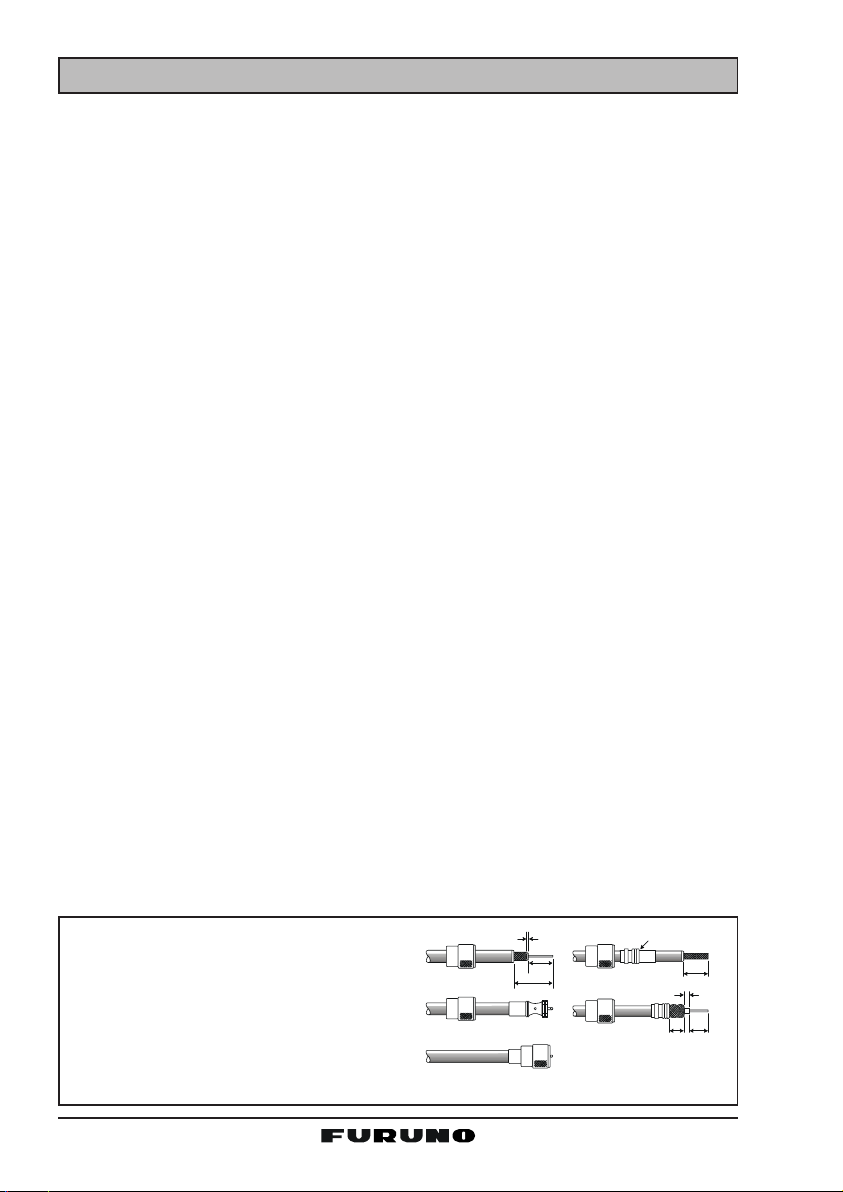
7.3 COAXIAL CABLE
VHF antennas are connected to the transceiver by means of a coaxial cable –
a shielded transmission line. Coaxial cables are specified by their diameters
and construction.
For runs less than 20 feet, RG-58/U, about 1/4-inch in diameter, is a good
choice. For runs over 20 feet but less than 50 feet, the larger diameter RG-8X
or RG-213/U should be used. Cable runs over 50 feet should use RG-8X. For
installation of the connector onto the coaxial cable see the figure below.
To get your coaxial cable through a
fitting and into your boat’s interior, you
may have to cut off the end plug and
reattach it later. You can do this if you
follow the directions that come with the
connector. Be sure to make good soldered connections.
1/16''
3/4''
1 1/8 ''
Adapter
1/8''
FM-4000Page 8
3/4''
5/8''3/8''
8 INSTALLATION
A
8.1 LOCATION
The radio can be mounted at any angle. Choose a mounting location that:
• is far enough from any compass to avoid any deviation in compass reading due to the speaker magnet (see the compass safe distances in the
Safety Instructions)
• provides easy access to the front panel controls and rear connectors
• allows connection to a power source and an antenna
• has nearby space for installation of a microphone hanger
• the antenna must be mounted at least three feet from the radio
Note: To insure the radio does not affect the compass or the radio’s performance is not affected by the antenna location, temporarily connect the radio in
the desired location and:
a. Examine the compass to see if the radio causes any deviation.
b. Connect the antenna and key the radio. Check to ensure the radio is
operating correctly by requesting a radio check.
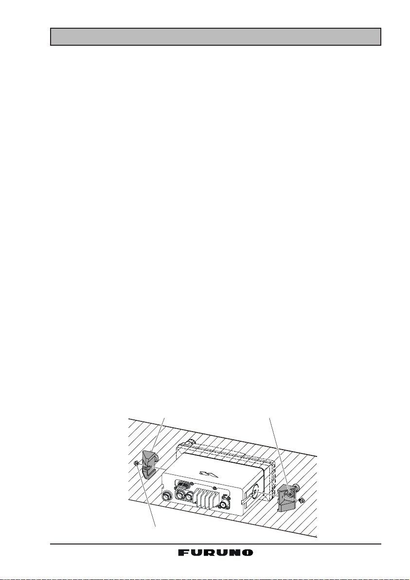
8.2 OPTIONAL MMB-84 FLUSH MOUNT INSTALLATION
1. Make a rectangular template for the flush mount measuring 2.9” H x 8.1”
W (72 x 205 mm).
2. Use the template to mark the location where the rectangular hole is to be
cut. Confirm that the space behind the dash or panel is deep enough to
accommodate the transceiver (at least six inches deep).
There should be at least 1/2 inch between the transceiver's heatsink and
any wiring, cables or structures.
3. Cut out the rectangular hole and insert the transceiver.
4. Fasten the brackets to the sides of the transceiver with the lock washer nut
combination so that the mounting screw base faces the mounting surface.
5. Turn the adjusting screw to adjust the tension so that the transceiver is
tight against the mounting surface.
Bracket
djusting Screw
Lock-washer nut combination
Page 9FM-4000

8.3 OPTIONAL CMP30 REMOTE MIC
The CMP30 Remote MIC permits remote control of the FM-4000’s radio, DSC
and PA/Fog functions. In addition the FM-4000 can operate as a full function
intercom system.
1. Connect the extension cable to the remote MIC eight pin connector on the
rear panel, then tighten the cable nut (See Figure 3).
2. Referring to Figure 3, make a 1.2” (30 mm) hole in the wall, then insert the
extension cable into this hole. Connect the gasket and mounting base to
the extension cable connector using the nut.
3. Drill the four screw holes (approx. 2 mm) on the wall, then install the mounting base to the wall using four screws.
Put the rubber cap onto the nut. The installation is now complete.
NOTE
The routing cable can be cut and spliced, however care needs to be
taken when reconnecting the wires to ensure water integrity.
Before cutting the cable, make sure it is not plugged into the radio. After
cutting you will notice there are the following wires:
Yellow, Green, Brown, Purple, Blue, Green, RedÚ, Shield
Ú The red and shield wires are wrapped in foil. Remove the foil, and
separate the red and shield wires.
Ú
Wall
Routing Cable
External Speaker Connections
Gasket
Mounting Bracket
Cap
Nut
FM-4000Page 10
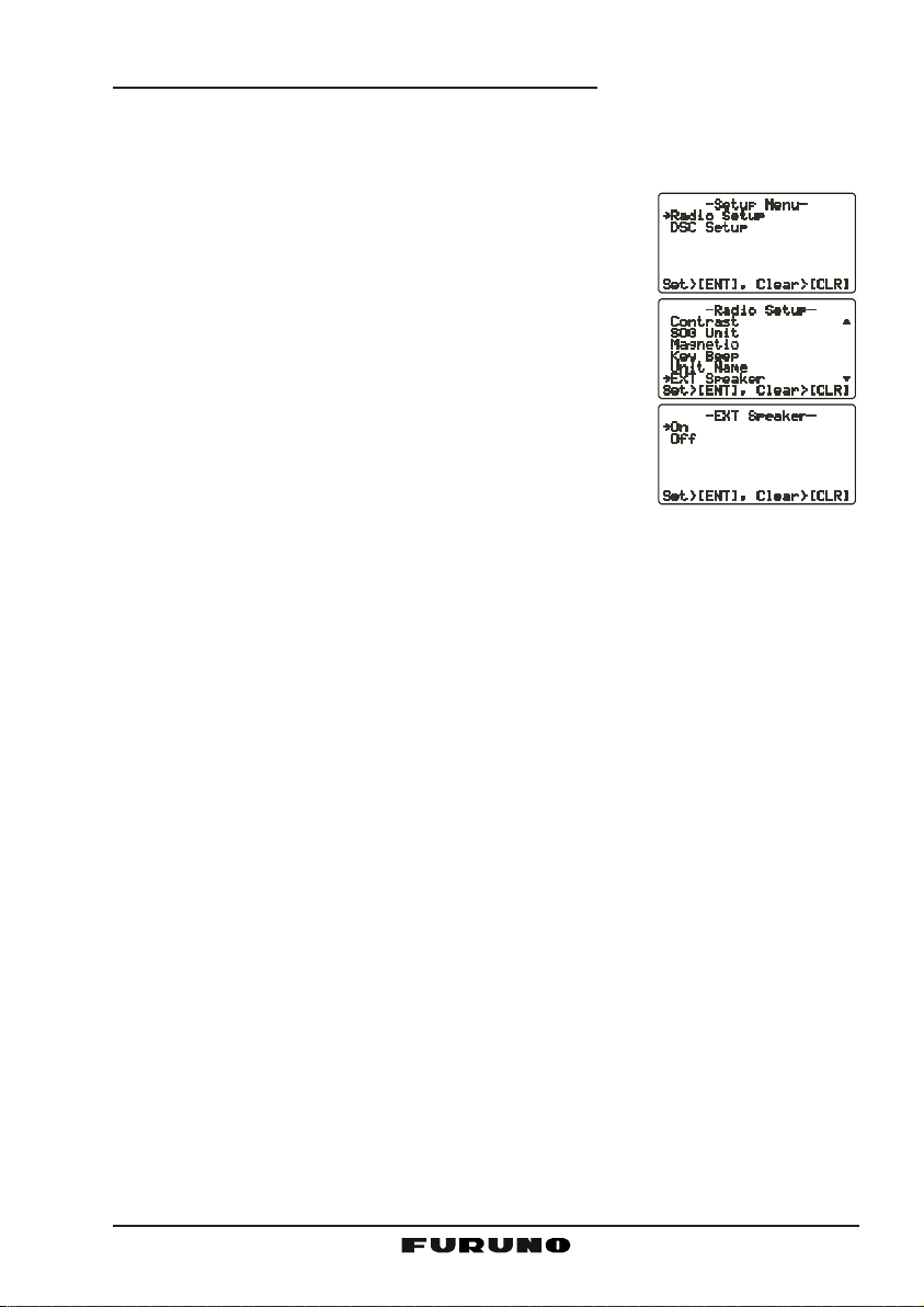
Remote MIC or External Speaker Selection
By default the internal speaker is turned on, however it can be turned off to use
the external speaker, when the Remote MIC is installed.
Remote MIC procedure
1. Press and hold down the [CALL(MENU)] key until
Radio SetupRadio Setup
the “
Radio Setup” menu appears.
Radio SetupRadio Setup
2. Press the [ENT] key, then use the [S] or [T] key to
select “
3. Press the [ENT] key.
4. Press the [S] or [T] key to select “
speaker off) or “
6. Press the [ENT] key to save the selection, then press
the [16/9] key to return to radio operation.
Ext SpeakerExt Speaker
Ext Speaker.”
Ext SpeakerExt Speaker
OnOn
On” (External speaker on).
OnOn
OffOff
Off” (External
OffOff
Page 11FM-4000
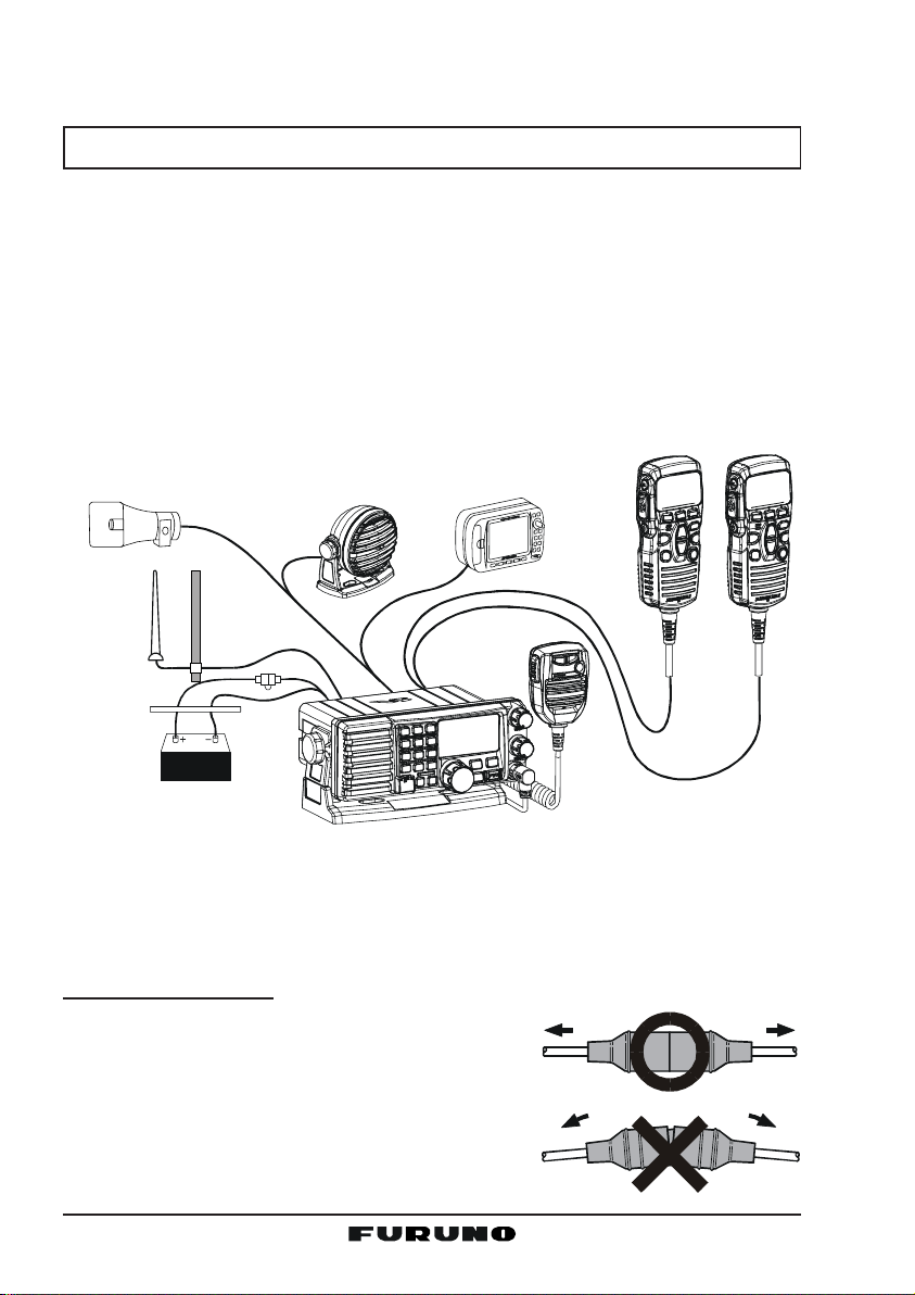
8.4 ELECTRICAL CONNECTIONS
CAUTION
Reverse polarity connections will damage the radio!
Connect the power cord and antenna to the radio. Antenna and power supply
connections are as follows:
1. Mount the antenna at least three feet away from the radio. At the rear of
the radio, connect the antenna cable. It must have a PL259 connector.
2. Connect the red power wire to a 13.8 VDC ±20% power source. Connect
the black power wire to a negative ground.
3. It is advisable to have a certified marine technician check the power output
and the standing wave ratio of the antenna after installation.
Optional CMP30 Remote MIC
Optional HAIL/PA Horn
Antenna
Red
Power Source
A
c
c
e
s
s
Water proof
Deck Outlet
Black
o
r
y
C
a
b
l
e
Fuse
Optional Speaker
GPS Navigation Receiver
Fuse Replacement
To take out the fuse from the fuse holder, hold the
both ends of the fuse holder and pull the fuse holder
apart, do not bend the fuse holder. When you replace the fuse, please confirm that the fuse is tightly
fixed on the metal contact located inside the fuse
holder. If the metal contact holding the fuse is loose,
the fuse holder may heat up.
FM-4000Page 12
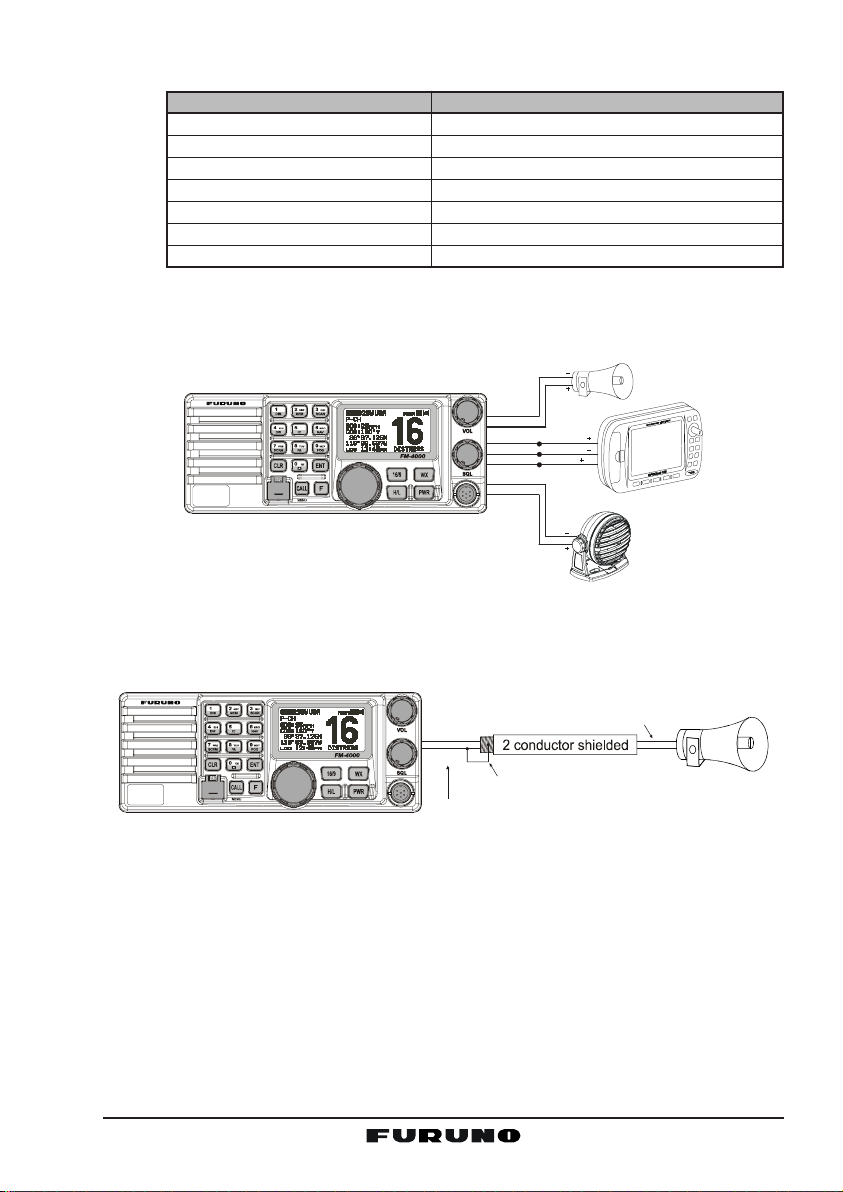
8.5 ACCESSORY CABLE
Wire Color/Description
WHITE - External Speaker (+
SHIELD - External Speaker
RED - PA Speaker (+
SHIELD - PA Speaker
)
(–)
GREEN - NMEA Ground
BLUE- NMEA Input (+)
GRAY-NMEA Output (+)
When connecting the PA speaker, external speaker or GPS receiver, strip off
about 1 inch (2.5 cm) of the specified wire’s insulation, then splice the ends
together.
-/*
JKL
DISTRESS
PULL OPEN
Note: In some areas powerful AM broadcast stations may be heard when in
listen-back mode. In this case change the speaker wire to 2-conductor shielded
audio cable. See the illustration below for connections.
Connection Examples
)
Connect to external 4 Ohm audio speaker
(–)
Connect to external 4 Ohm audio speaker
Connect to external 4 Ohm PA speaker
Connect to external 4 Ohm PA speaker
Connect to NMEA
(–)
connection of GPS
Connect to NMEA (+) output of GPS
Connect to NMEA (+) input of GPS
PA Spe ake r
Shield
Red
Blue NMEA OUT
Green
Gray
Shield
White
NMEA OUT
NMEA IN
( )
( )
( )
GPS Receiver
External Speaker
-/*
JKL
Red
Shield of cabl e is not
attached on PA Speaker end
Bare
DISTRESS
PULL OPEN
Connect the bare wire from t he GX5500S
to one wire an d to the shielded.
Make Red and bare connectio ns short as possible
PA Sp eaker
• The GPS receiver must have its NMEA output turned on and baud rate set
to “4800” in the Setup menu. If there is a selection for parity, select “None”.
• For further information on interfacing /setting up your GPS receiver, please
refer to its Operator’s Manual.
• FM-4000 can read NMEA-0183 version 2.0 or higher.
• The NMEA supported sentences are:
Input: GLL, GGA, RMC and GNS (RMC sentence is recommended)
Output: DSC and DSE
(DSC sentences to FURUNO plotter for position polling)
Page 13FM-4000
 Loading...