

Furuno USA 9ZWFA170 Installation Manual

A
Installation Manual
CLASS A AIS
Model FA-170
PRODUCT NAME: U-AIS TRANSPONDER
SAFETY INSTRUCTIONS ................................................................................................i
SYSTEM CONFIGURATION ...........................................................................................ii
EQUIPMENT LISTS........................................................................................................ iii
1. MOUNTING..............................................................................................................1-1
1.1 How to Install the Antenna Unit(s) .....................................................................................1-1
1.2 How to Install the FA-1702 Monitor Unit ............................................................................1-7
1.3 How to Install the FA-1701 Transponder Unit..................................................................1-12
1.4 How to Install the PR-240 Power Supply (option)............................................................1-13
1.5 How to Install the FA-1703 Pilot Plug Unit (option)..........................................................1-14
2. WIRING....................................................................................................................2-1
2.1 Connection Overview.........................................................................................................2-1
2.2 How to Fabricate the Cables..............................................................................................2-2
2.3 Unit Interconnection...........................................................................................................2-4
2.4 How to Terminate COM ports (For IEC 61162-1/2 signal).................................................2-8
2.5 How to Change the Ship’s Mains Specifications................................................................2-9
3. SETTING AND ADJUSTMENT ...............................................................................3-1
3.1 How to Set MMSI, IMO No., Name and Call Sign..............................................................3-2
3.2 Inland AIS Specific Settings...............................................................................................3-3
3.3 How to Set GPS Antenna Position.....................................................................................3-5
3.4 How to Enable and Disable Alerts .....................................................................................3-6
3.5 How to Set Up the I/O Ports...............................................................................................3-7
3.6 Network Set Up..................................................................................................................3-8
3.7 SERVICE Menu Operations...............................................................................................3-9
APPENDIX 1 JIS CABLE GUIDE .............................................................................AP-1
APPENDIX 2 DIGITAL INTERFACE ........................................................................AP-2
PACKING LISTS ......................................................................................................... A-1
OUTLINE DRAWINGS ................................................................................................ D-1
INTERCONNECTION DIAGRAM ................................................................................ S-1
www.furuno.com
ll brand and product names are trademarks, registered trademarks or service marks of their respective holders.
(GREG) FA-170
IME-44900-Z10
Z10
OCT. 30, 2015:
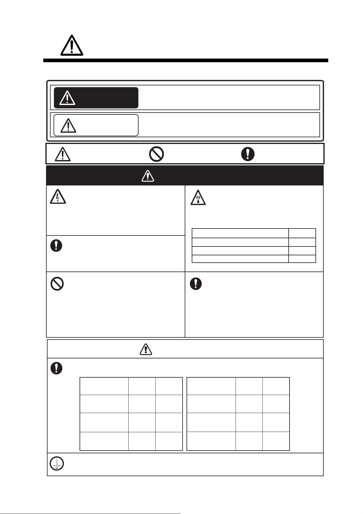
SAFETY INSTRUCTIONS
WARNINGWARNING
Be sure that the power supply is
compatible with the voltage rating of
the equipment.
Connection of an incorrect power supply
can cause fire or damage the equipment.
The voltage rating of the equipment
appears on the label above the power
connector.
CAUTIONCAUTION
FA-1703
Pilot Plug unit
Indicates a potentially hazardous situation which, if not avoided,
could result in death or serious injury.
Warning, Caution Prohibitive ActionProhibitive Action
Indicates a potentially hazardous situation which, if not avoided,
can result in minor or moderate injury.
WARNING
CAUTION
ELECTRICAL SHOCK HAZARD
Do not open the equipment unless
totally familiar with electrical circuits
and service manual.
Only qualified personnel should work
inside the equipment.
Turn off the power at the switchboard
before beginning the installation.
Fire or electrical shock can result if the
power is left on.
Do not install the equipment where it
may get wet from rain or water
splash.
Water in the equipment can result in
fire, electrical shock or damage the
equipment.
Observe the following compass safe distances to prevent interference to a magnetic
compass:
Standard
compass
Steering
compass
FA-1701
Transponder unit
FA-1702
Monitor unit
Attach protective earth securely to the ship's body.
The protective earth is required to the power supply to prevent electrical shock.
1.70 m 1.10 m
0.65 m 0.40 m
0.35 m 0.30 m
GVA-100-T
Standard
compass
Steering
compass
0.40 m 0.30 m
DB-1
0.30 m 0.30 m
PR-240
0.90 m 0.60 m
Do not approach the antenna closer
than listed below when it is
transmitting.
The antenna emits radio waves that
can be harmful to the human body.
RF power density on antenna aperture Distance
100 W/m
2
10 W/m
2
2 W/m
2
0.09 m
0.04 m
N/A
Equipment Equipment
The installer must read the safety instructions before attempting to install this equipment.
i
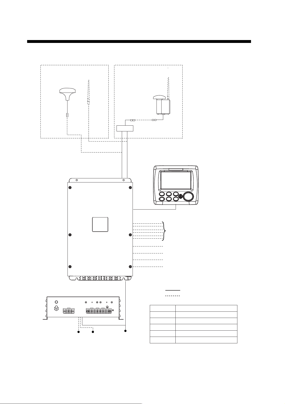
SYSTEM CONFIGURATION
GPS/VHF
combined antenna
GVA-100-T
GPS antenna
GPA-017S
Distributor unit
DB-1
VHF antenna
VHF antenna
Power supply
PR-240
100/110/115/200/
220/230 VAC
1
ø, 50/60Hz
12-24 VDC
OR
24 VDC
MONITOR UNIT
FA-1702
(two units may
be connected)
External display, NavNet2,
NavNet 3D, Pilot plug (FA-1703),
Sensor
Beacon receiver
Alarm system
LAN
Blue Sign
GPS-017S Exposed to the weather
GVA-100-T
FA-1701
FA-1702
DB-1
PR-240
Exposed to the weather
Protected from the weather
Protected from the weather
Protected from the weather
Protected from the weather
:
Standard supply
:
Optional or local supply
TRANSPONDER UNIT
FA-1701
ii
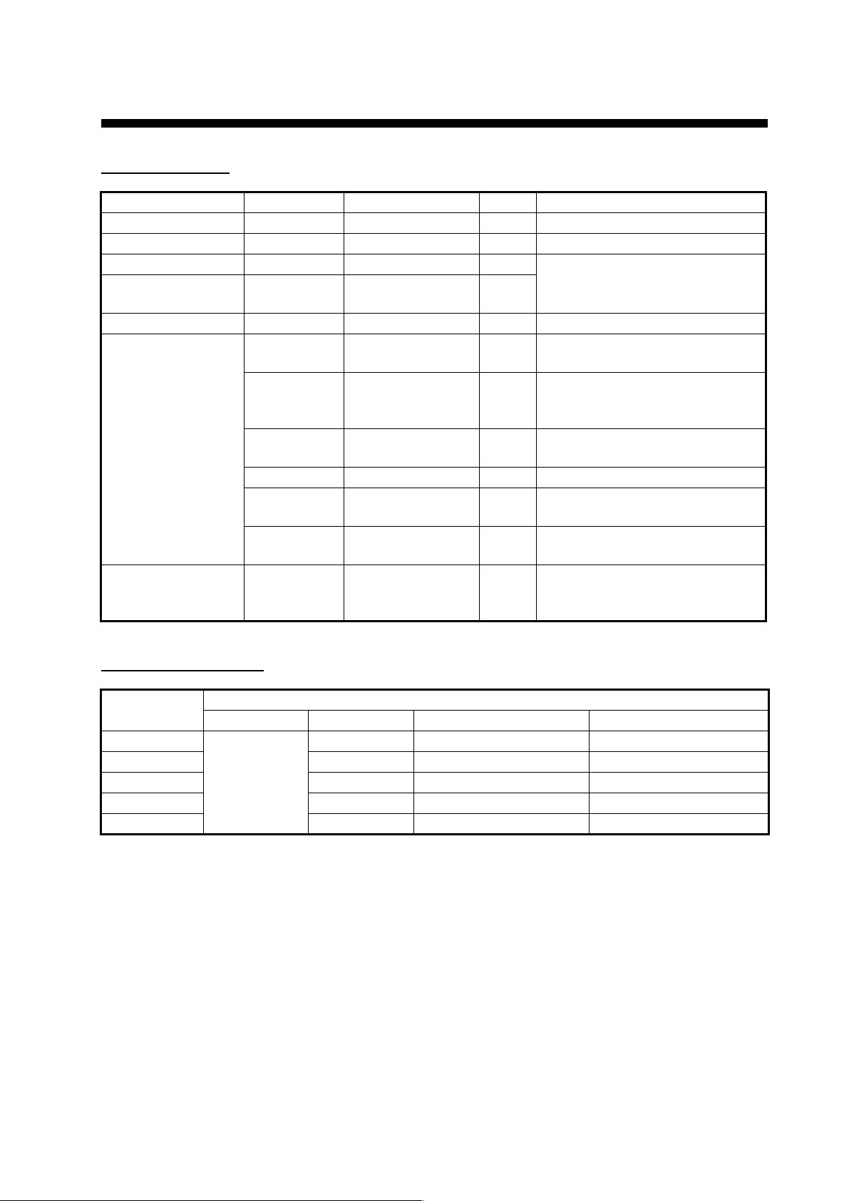
EQUIPMENT LISTS
Standard supply
Name Type Code no. Qty Remarks
Transponder unit FA-1701 — 1
Monitor Unit FA-1702 — 1
GPS Antenna GPA-017S — 1 Select one.
GPS/VHF Com-
bined Antenna
Distributor Unit DB-1 — 1 For GVA-100-T.
Installation Materi-
als
Spare Parts SP05-06501 001-426-300
GVA-100-T
CP05-13600 000-029-284
CP05-13610 000-029-285
CP05-13620 000-029-286
CP24-00141 001-176-030 1 For GVA-100-T.
CP05-13630 000-029-287
CP05-13640 000-029-288
—
1
For DB-1 (GVA-100-T).
1
See table below for contents.
For DB-1 (GVA-100-T, Deep
1
Sea) and GPA-017S.
See table below for contents.
For DB-1 (GVA-100-T).
1
See table below for contents.
For GPA-017S.
1
See table below for contents.
For GPA-017S.
1
See table below for contents.
For FA-1701
1
(Type: FGMB 125V 8A PBF, 2
pcs. Code: 000-191-004-10).
Installation materials
Installation
materials
CP05-13600
CP05-13610 N N N
CP05-13620 Y Y N
CP05-13630 N Y N
CP05-13640 N Y Y
CP05-13601 CP24-00101 Z-AWG25X4P-SB L050 TNC-PS/PS-3D-L15M-R
YN N
Y
Contains
iii

EQUIPMENT LISTS
Optional supply
Name Type Code no. Qty Remarks
Pilot Plug Unit FA-1703 — 1
Monitor Unit FA-1702 — 1
Power Supply Unit PR-240 — 1
Antenna Cable As-
sembly
Antenna Cable Set CP24-00300 000-041-938 1 For GVA-100. (30 m)
Mast Mounting Kit CP20-01111 004-365-780 1 For GPA-017S.
Antenna Fixing
Bracket
AD Converter AD-100-E 000-040-110 1
Mast Mounting Kit OP24-5 005-954-510 1 For GVA-100-T.
Front Fixing Panel OP24-35 001-247-240 1 For FA-1702.
F Mount Cushion Kit OP05-141 001-436-880 1
Installation Materials CP03-28900 (10M) 000-082-658 1 LAN cable (10 m).
Antenna FAB-151D 001-144-490-10 1
Right Angle Mounting
Base
L-Angle Mounting
Base
Handrail Mounting
Base
Antenna Fixing
Bracket
Cable Assembly TNC-PS/PS-3D-
Water Proof Kit OP05-139 001-426-500 1 For FA-1702.
Replacement Kit OP05-140 001-426-510 1 For FA-1702.
CP20-02700 (30M) 004-381-160 1 For GPA-017S. (30 m)
CP20-02710 (50M) 004-381-170 1 For GPA-017S. (50 m)
CP20-02720 (40M) 001-207-990 1 For GPA-017S. (40 m)
CP24-00310 000-041-939 1 For GVA-100. (50 m)
CP24-00320 000-022-637 1 For GVA-100. (40 m)
CP05-14001 001-430-360
CP03-28910 (20M) 000-082-659 1 LAN cable (20 m).
CP03-28920 (30M) 000-082-660 1 LAN cable (30 m).
CP03-28930 (50M) 000-084-368 1 LAN cable (50 m).
CP03-28940 (100M) 000-090-429 1 LAN cable (100 m).
NO. 13-QA330 001-111-910-10
NO. 13-QA310 001-111-900-10
NO. 13-RC5160 001-111-920-10
4-310071 000-166-333-10
001-173-110-10
L15M-R
Z-AWG25X4P-SB
L050
Z-AWG25X4P-SB
L100
001-426-390
001-426-440
1
For GPA-017S.
1
For GPA-017S.
1
For GPA-017S.
1
For FAB-151D.
1
For connection to
1
GPA-017S.
For connection be-
tween FA-1701 and
1
FA-1702. Contains ZAWG25X4P-SB L050
(5 m)
For connection between FA-1701 and
1
FA-1702. Contains ZAWG25X4P-SB L100
(10 m)
iv
1. MOUNTING
NOTICE
Do not apply paint, anti-corrosive sealant or contact spray
to coating or plastic parts of the equipment.
Those items contain organic solvents that can damage coating
and plastic parts, especially plastic connectors.
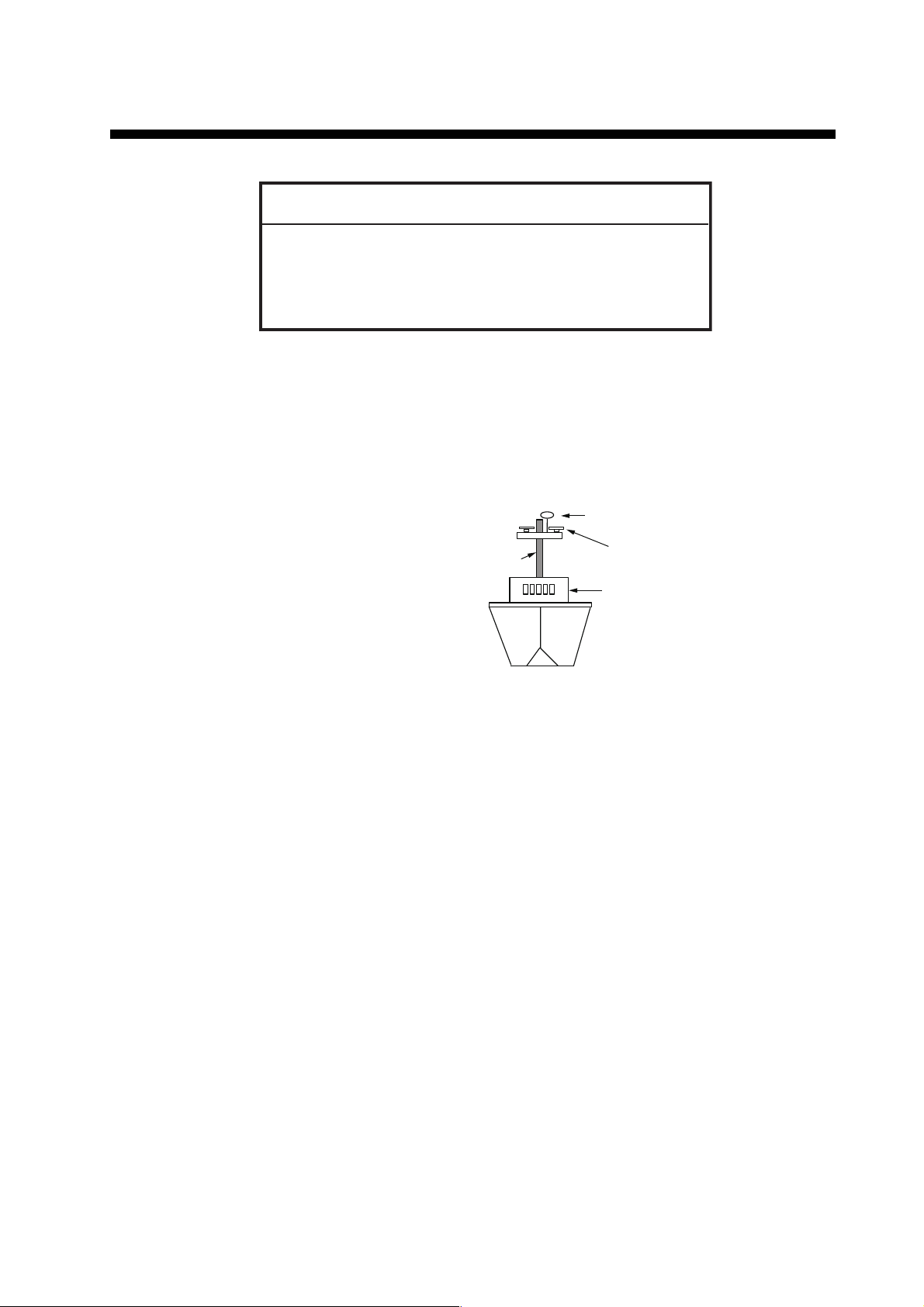
Mast
Other Antennas
Bridge
GPA-017S or GVA-100-T or FAB-151D
1.1 How to Install the Antenna Unit(s)
1.1.1 Mounting considerations for all antenna units
When selecting a mounting location for the antenna, keep in mind the following points.
• Select a location out of the radar
beam. The radar beam will obstruct
or prevent reception of the GPS
satellite signal.
• There should be no interfering object within the line-of-sight to the
satellites. Objects within line-ofsight to a satellite, for example, a
mast, may block reception or prolong acquisition time.
• Mount the antenna unit as high as possible to keep it free of interfering objects and
water spray, which can interrupt reception of GPS satellite signal if the water freezes.
• Referring to the drawing at the back if this manual, leave sufficient space between
all antennas to avoid mutual interference.
For VHF antennas, also keep in mind the following points:
• The AIS VHF antenna should be placed in an elevated position that is as free as
possible with a minimum of 0.5 meters in the horizontal direction from constructions
made of conductive materials. The antenna should not be installed close to any
large vertical obstruction. The objective for the AIS VHF antenna is to see the horizon freely through 360 degrees.
• The AIS VHF antenna should be installed safely away from interfering high-power
energy sources like radar and other transmitting radio antennas, preferably at least
3 meters away from and out of the transmitting beam.
• There should not be more than one antenna on the same plane. The AIS VHF antenna should be mounted directly above or below the ship’s primary VHF radiotelephone antenna, with no horizontal separation and with a minimum of 2.8 meters
vertical separation. If it is located on the same plane as other antennas, the distance
apart should be at least 10 meters.
1-1
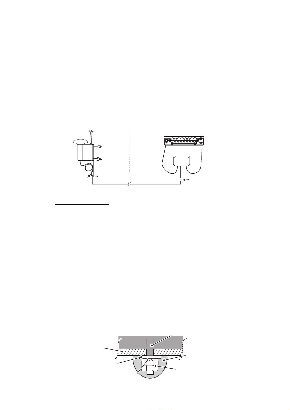
1. MOUNTING
Outdoor
Indoor
N-P-8DFB
N-P-8DFB
Distributor DB-1Distributor DB-1
GPS
AIS TransponderAIS Transponder
VHF
RG-10U/Y
Mounting platform
Hex nuts
Bolt
Spring washer
Flat washer
Coat with
marine sealant
Antenna baseAntenna base
1.1.2 GPS/VHF combined antenna (GVA-100-T)
Install the combined antenna unit referring to the outline drawing. When selecting a
mounting location for the antenna, keep in mind the following points.
• Select a location out of the radar beam. The radar beam will obstruct or prevent reception of the GPS satellite signal.
• There should be no interfering object within the line-of-sight to the satellites. Objects
within line-of-sight to a satellite, for example, a mast, may block reception or prolong
acquisition time.
• Mount the antenna unit as high as possible. Mounting it this way keeps it free of interfering objects and water spray, which can interrupt reception of GPS satellite signal if the water freezes.
• Also, refer to the antenna installation guidelines on page 1-6.
Installation overview of GPS/VHF combined antenna
Mounting procedure
1. Dismount the bottom cover, cut the cable-tie inside the unit and take out the co-
axial connector attached to the combined box.
2. Loosen four screws to loosen whip antenna fixture and pull out the coaxial con-
nector coming from the combined box through the hole in the whip antenna fixture.
3. Connect the coaxial connector to the whip antenna base and wrap the junction
part of the whip antenna with vulcanizing tape and then vinyl tape for waterproofing.
4. Insert the whip antenna from the top of the combined antenna.
5. Secure the whip antenna with whip antenna fixture.
6. Using a new cable tie (supplied), secure the cables and coaxial connector inside
the antenna case.
7. Mount the bottom cover.
8. Fix the GPS/VHF combined antenna to the ship’s stanchion (40 to 50 mm diame-
ter) with antenna fixing brackets, flat washers and hex. nuts.
Note: Coat the exposed parts of bolts and nuts with marine sealant (local supply).
1-2
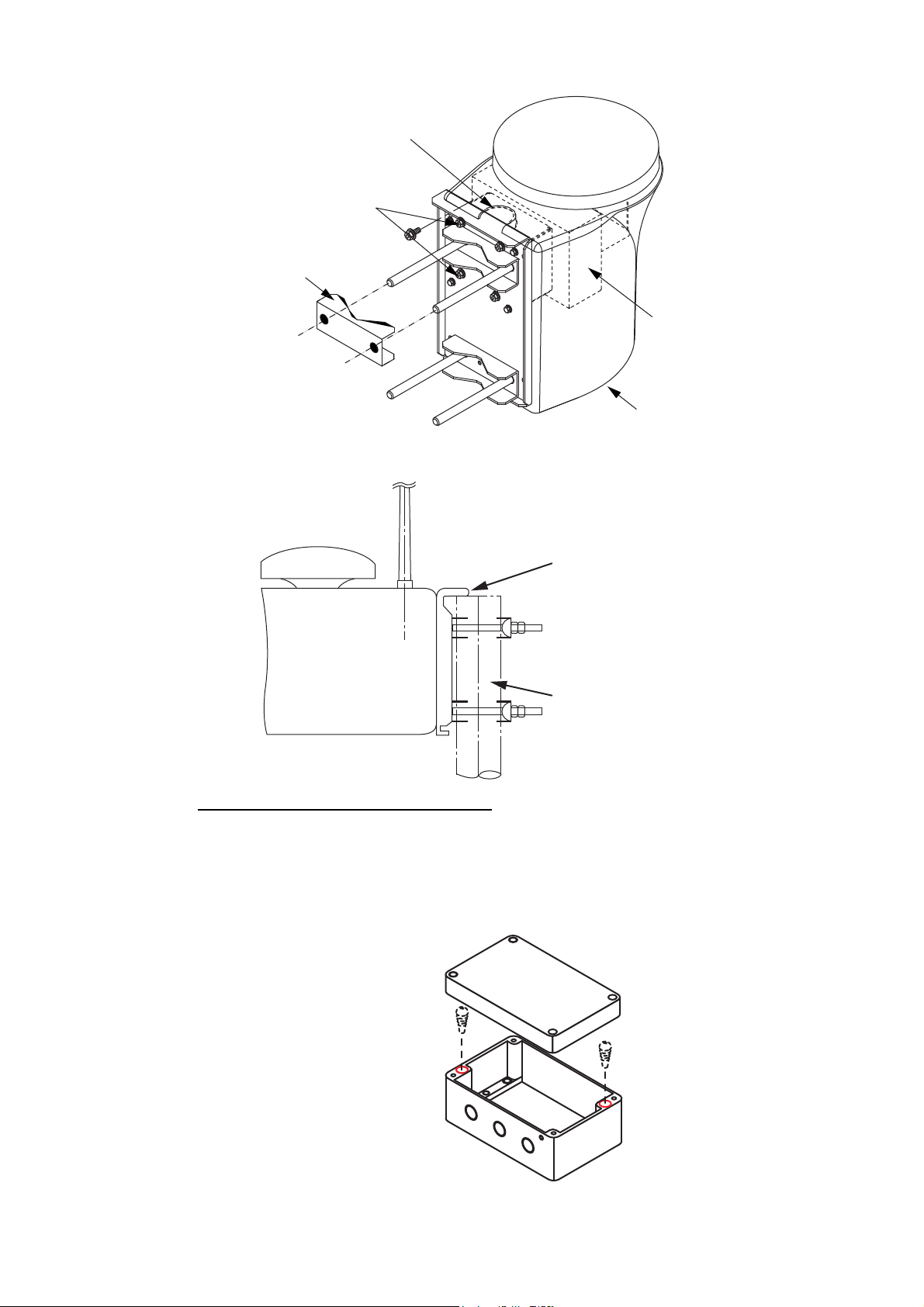
A
Whip antenna fixture
Stanchion
The antenna flange
should be placed at
the top of the
stanchion to prevent
the antenna from
slipping down the
stanchion.
Loosen four screws.
(M5x16)
ntenna fixing bracket
GPS/VHF Combined antenna
1. MOUNTING
Combined box
Bottom cover
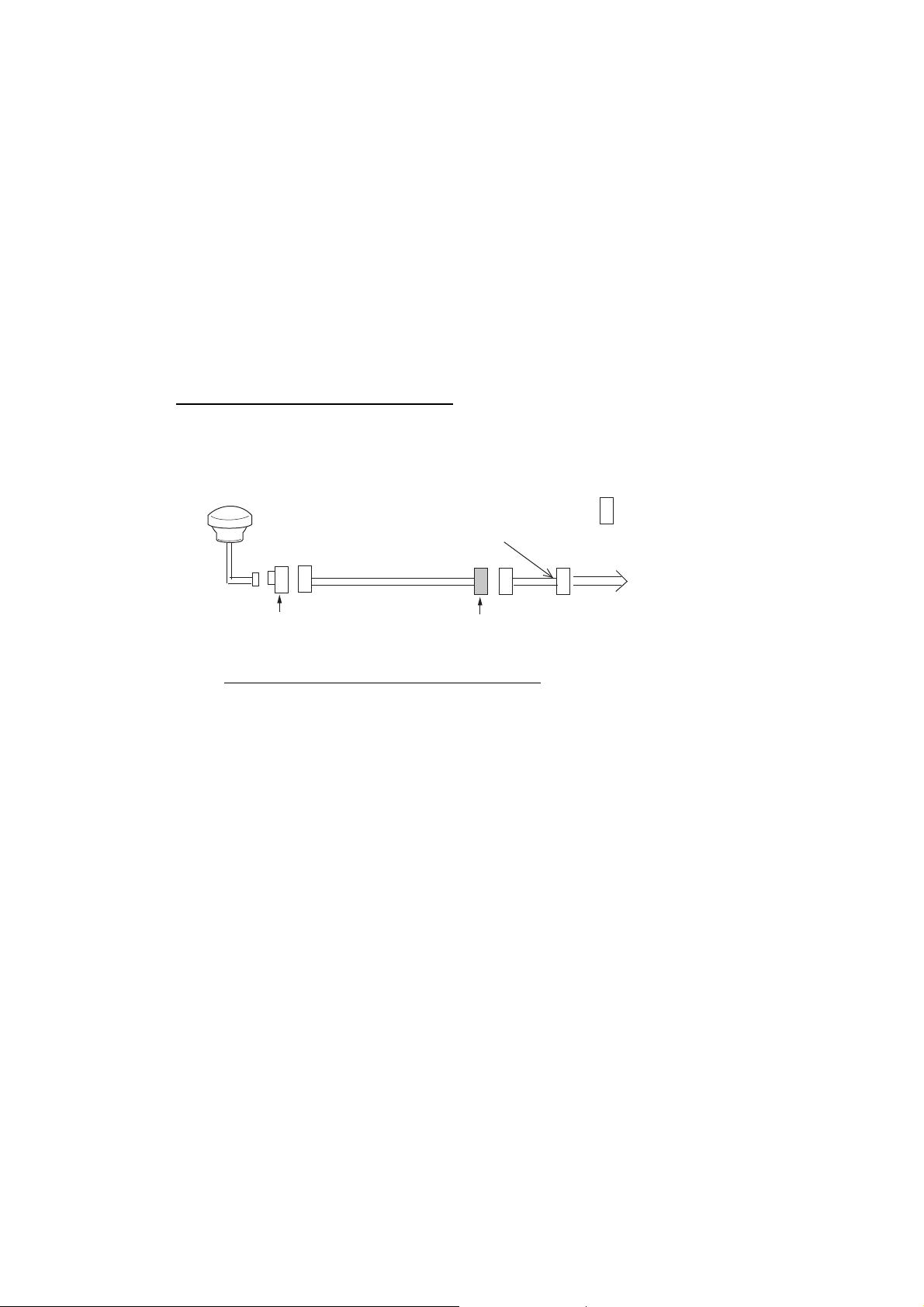
How to install distributor unit DB-1
The length of the cable between the distributor unit and transponder unit is 1 m so locate the distributor unit within 1 m from the transponder unit. Fix the distributor unit on
the bulkhead, facing the cable entrance downward. Remove the lid of the distributor
unit and secure the unit with two self-tapping screws.
Self-tapping screw
(4x30)
Note: Be sure no foreign material or water enters the distributor unit.
1-3
1. MOUNTING
Antenna Unit
Antenna Cable
30m 1 m
Fabricate locally. (See next page.)
N-P-8DFB
FA-1701
: Connector
Conversion
Cable Assy.
NJ-JP-3DXV-1
TNCP-NJ
0.6m
1.1.3 GPS antenna unit (GPA-017S)
Install the GPS antenna unit referring to the outline drawing at the back of this manual.
When selecting a mounting location for the antenna, keep in mind the following points.
• Select a location out of the radar beam. The radar beam will obstruct or prevent reception of the GPS satellite signal.
• There should be no interfering object within the line-of-sight to the satellites. Objects
within line-of-sight to a satellite, for example, a mast, may block reception or prolong
acquisition time.
• Mount the antenna unit as high as possible to keep it free of interfering objects and
water spray, which can interrupt reception of GPS satellite signal if the water freezes.
How to extend the antenna cable
Three types of antenna cable extensions are optionally available.
a) Antenna cable set CP20-02700
Securing and waterproofing the connector
Referring to the figures in section 2.2.1 secure and waterproof the connections.
b) Antenna cable set CP20-02720 (8D-FB-CV, 40m)/CP20-02710 (8D-FB-CV, 50m)
Connect the cable the same as a) above.
c) Cable type RG-10/UY (shipyard supply)
Note: The length of this cable should be less than 20 m to prevent signal loss. The
coax. coupling cable assy.(type: NJ-TP+3DXV-1, code no. 000-123-809-10), coaxial connector (N-P-8DFB; supplied), vulcanizing tape and vinyl tape are required. Fabricate both ends of the cable as shown in the figure on the next page.
1-4
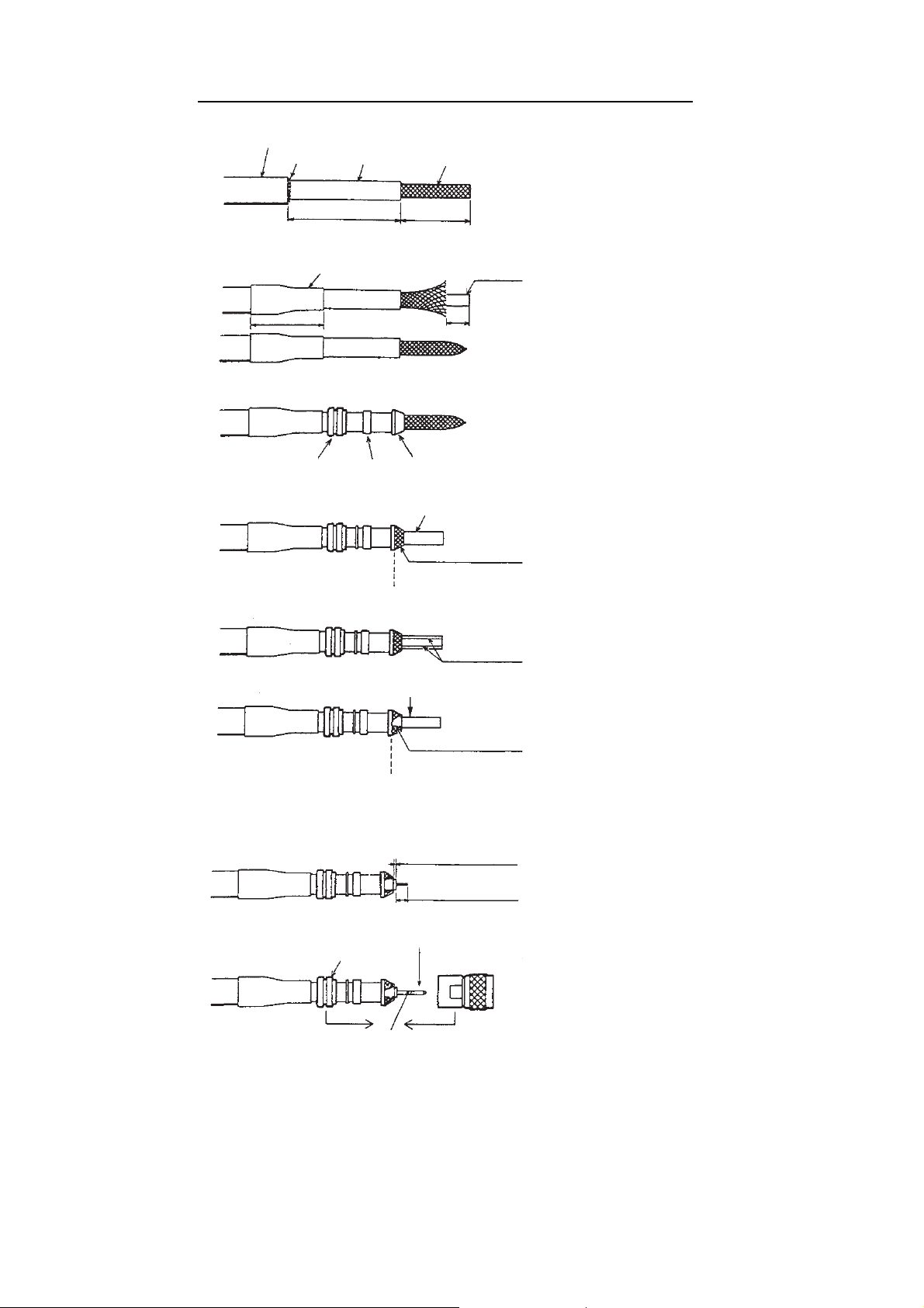
How to attach the connector N-P-8DFB for cable 8D-FB-CV
Outer Sheath
Armor
Dimensions in millimeters.
Inner Sheath Shield
Remove outer sheath and armor by the
dimensions shown left.
Expose inner sheath and shield by the
dimensions shown left.
Cut off insulator and core by 10mm.
Twist shield end.
Slip on clamp nut, gasket and clamp as
shown left.
Fold back shield over clamp and trim.
Cut aluminum foil at four places, 90° from one
another.
Fold back aluminum foil onto shield and trim.
Expose the insulator by 1mm.
Expose the core by 5mm.
Slip the pin onto the conductor. Solder them
together through the hole on the pin.
Insert the pin into the shell. Screw the clamp
nut into the shell.
(Tighten by turning the clamp nut. Do not
tighten by turning the shell.)
Cover with heat-shrink tubing and heat.
30
10
Clamp
Nut
Gasket
(reddish
brown)
Clamp
Aluminum Foil
Trim shield here.
Trim aluminum
tape foil here.
Insulator
1
5
Clamp Nut
Pin
Shell
Solder through
the hole.
50
30
1. MOUNTING
1-5
 Loading...