

Page 1

OPERATOR'S MANUAL
MARINE RADAR
FCR-2107
FCR-2107-BB
FCR-2107-D
FCR-2807
MODEL
FCR-2807-D
www.furuno.co.jp
Page 2

9-52 Ashihara-cho,
*
00015804115
**00015804115
*
Nishinomiya, 662-8580, JAPAN
Telephone : +81-(0)798-65-2111
Fax :+81-(0)798-65-4200
The paper used in this manual
is elemental chlorine free.
・FURUNO Authorized Distributor/Dealer
All rights reserved.
Pub. No. OME-35590-F
(DAMI ) FCR2837SD
Printed in Japan
A : JUL 2006
.
F : MAR . 11, 2011
*00015804115**00015804115*
* 0 0 0 1 5 8 0 4 1 1 5 *
Page 3
Important Notices
Ni-Cd Pb
General
• The operator of this equipment must read and follow the descriptions in this manual. Wrong operation or
maintenance can cancel the warranty or cause injury.
• Do not copy any part of this manual without written permission from FURUNO.
• If this manual is lost or worn, contact your dealer about replacement.
• The contents of this manual and equipment specifications can change without notice.
• The example screens (or illustrations) shown in this manual can be different from the screens you see on your
display. The screens you see depend on your system configuration and equipment settings.
• Save this manual for future reference.
• Any modification of the equipment (including software) by persons not authorized by FURUNO will cancel the
warranty.
• All brand and product names are trademarks, registered trademarks or service marks of their respective holders.
How to discard this product
Discard this product according to local regulations for the disposal of industrial waste. For disposal in the USA, see
the homepage of the Electronics Industries Alliance (http://www.eiae.org/) for the correct method of disposal.
How to discard a used battery
Some FURUNO products have a battery(ies). To see if your product has a battery, see the chapter on Maintenance.
Follow the instructions below if a battery is used. Tape the + and - terminals of battery before disposal to prevent
fire, heat generation caused by short circuit.
In the European Union
The crossed-out trash can symbol indicates that all types of batteries must not be
discarded in standard trash, or at a trash site. Take the used batteries to a battery
collection site according to your national legislation and the Batteries Directive
2006/66/EU.
In the USA
The Mobius loop symbol (three chasing arrows) indicates that Ni-Cd and leadacid rechargeable batteries must be recycled. Take the used batteries to a battery
collection site according to local laws.
In the other countries
There are no international standards for the battery recycle symbol. The number
of symbols can increase when the other countries make their own recycling symbols in the future.
Cd
i
Page 4
Safety Instructions
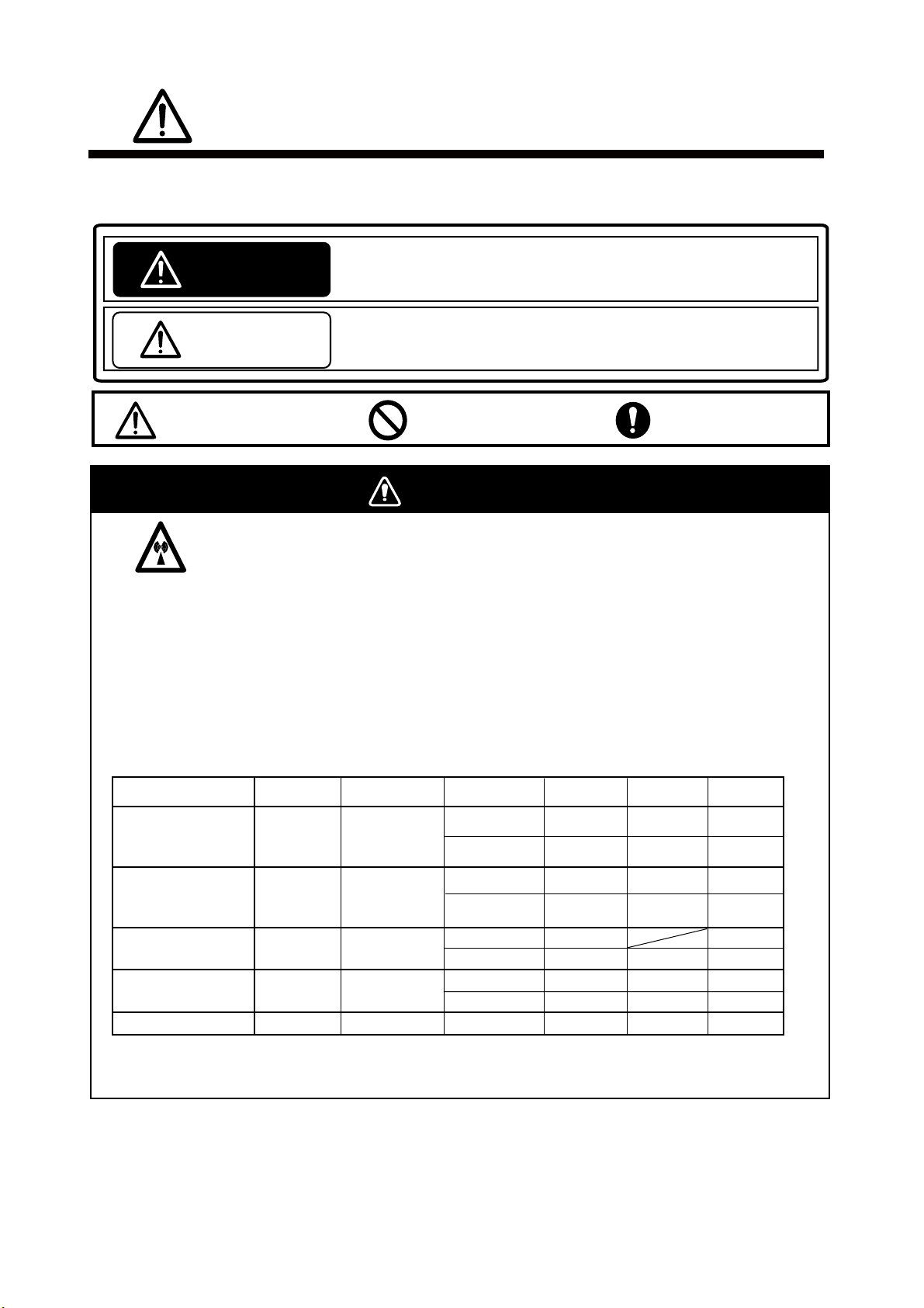
SAFETY INSTRUCTIONS
The operator must read the applicable safety instructions before attempting to operate the equipment.
Indicates a potentially hazardous situation which, if not avoided,
WARNING
CAUTION
Warning, Caution
could result in death or serious injury.
Indicates a potentially hazardous situation which, if not avoided,
can result in minor or moderate injury.
Prohibitive Action
Mandatory Action
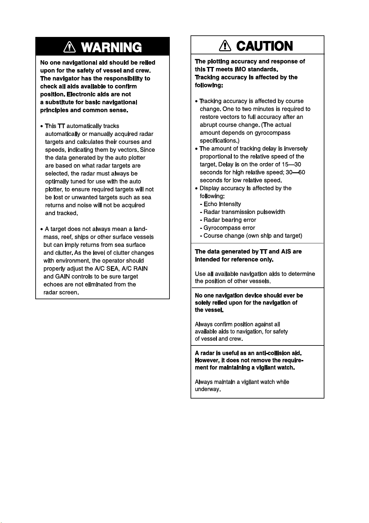
WARNING
Radio Frequency Radiation Hazard
The radar antenna emits electromagnetic radio frequency (RF) energy which can be harmful,
particularly to your eyes. Never look directly into the antenna aperture from a close distance
while the radar ius in operation or eexpose yourself to the transmitting antenna at a close
distance. Distances at which RF radiation level of 100, 50 and 10 W/m are given in the table
below.
Note: If the antenna unit is installed at a close distance in front of the wheel house, your
administration may require halt of transmission within a certain sector of antenna revolution.
This is possible. Ask your FURUNO representive or dealer to provide this feature.
Radar model
FCR-2117(-BB,-D)
FCR-2817(-D)
FCR-2127(-BB,-D)
FCR-2827(-D)
FCR-2137S(-BB,-D)
FCR-2837S(-D)
FCR-2827W(-D)
FCR-2837SW(-D)
Transceiver
RTR-078
RTR-079 MG5436
RTR-080
RTR-081
RTR-082
Magnetron
MG4010
MG5223F
MG5436
MG5223F
Antenna
*2
XN20AF
XN24AF
XN20AF
XN24AF
SN30AF
SN36AF
XN20AF
XN24AF 0.2m 3.4m
SN36AF
*1
100W/m
0.1m
0.1m
0.5m
0.2m
0.1m
0.1m
0.4m
-
2
2
50W/m
0.7m
0.4m
1.7m
1.0m
0.7m
1.0m
0.5m
0.2m
2
10W/m
2.2m
1.5m
4.6m
3.3m
2.4m
2.0m
5.6m
1.9m
2
*1
XN12AF: 120cm, XN20AF: 198cm, XN24AF: 243cm, SN30AF: 309cm, SN36AF: 377cm
*2
OR MAF1425B
ii
Page 5

Safety Instructions
iii
Page 6
Safety Instructions
iv
Page 7

Table of Contents
Foreword..................................................................................................................................................xv
System Configuration .......................................................................................................................... xvii
1. Operational Overview................................................................................................................... 1-1
1.1 Units of the System ............................................................................................................... 1-1
1.1.1 Control units .............................................................................................................. 1-1
1.1.2 Chart processor unit.................................................................................................. 1-3
1.2 How to Turn the Power On/Off............................................................................................. 1-3
1.3 Monitor Brilliance ................................................................................................................. 1-4
1.4 Menu Operation..................................................................................................................... 1-5
1.5 The Trackball Module ........................................................................................................... 1-7
1.5.1 The scrollwheel .......................................................................................................... 1-7
1.5.2 How to call menus and functions by the mouse buttons......................................... 1-8
1.6 Operation Modes.................................................................................................................... 1-9
1.6.1 When chart radar mode can be used ........................................................................ 1-9
1.6.2 How to switch modes ................................................................................................. 1-9
1.7 How to Configure Hot Keys F1-F4 ..................................................................................... 1-10
1.8 Geodetic Datum ................................................................................................................... 1-11
1.9 Navigation Marks on Chart Radar and ECDIS Modes..................................................... 1-11
1.9.1 EBL operation.......................................................................................................... 1-12
1.9.2 VRM operation......................................................................................................... 1-12
1.9.3 How to shift the reference point of EBL and VRM................................................ 1-13
1.10 Ship’s Position...................................................................................................................... 1-14
1.11 How to Customize Operation .............................................................................................. 1-15
1.12 Alerts Description................................................................................................................ 1-16
1.13 Charts................................................................................................................................... 1-17
1.14 Route Monitor ...................................................................................................................... 1-17
1.15 Switching Hub HUB-100 .................................................................................................... 1-18
2. Radar Operation............................................................................................................................ 2-1
2.1 Display Indications................................................................................................................ 2-1
2.1.1 Radar mode ................................................................................................................ 2-1
2.1.2 Chart radar mode ...................................................................................................... 2-2
2.2 How to Tune the Receiver..................................................................................................... 2-3
2.2.1 How to select the tuning method .............................................................................. 2-3
2.2.2 How to initialize tuning............................................................................................. 2-3
2.2.3 Automatic tuning....................................................................................................... 2-3
2.2.4 Manual tuning ........................................................................................................... 2-3
2.3 How to Set the Heading ........................................................................................................ 2-4
2.4 Presentation Modes............................................................................................................... 2-5
2.4.1 Presentation modes ................................................................................................... 2-5
2.4.2 Description of presentation modes ........................................................................... 2-5
2.5 How to Input Your Ship's Speed........................................................................................... 2-8
2.5.1 Speed selection for SPD and SB (TT, AIS and trails) ............................................. 2-8
2.5.2 Speed selection for COG and SOG (navigation) ...................................................... 2-9
2.5.3 Manual speed input................................................................................................. 2-10
2.6 How to Select the Range Scale ........................................................................................... 2-11
2.7 How to Adjust the Sensitivity............................................................................................. 2-11
2.8 How to Suppress Sea Clutter.............................................................................................. 2-11
2.8.1 Automatic adjustment by the A/C SEA control ..................................................... 2-12
2.8.2 Manual adjustment of A/C SEA.............................................................................. 2-12
2.9 How to Suppress Rain Clutter............................................................................................ 2-13
2.9.1 How to turn AUTO RAIN on or off ......................................................................... 2-13
2.9.2 How to adjust A/C RAIN ......................................................................................... 2-13
2.10 Interference Rejector ...........................................................................................................2-15
v
Page 8

Table of Contents
2.11 How to Measure the Range to a Target.............................................................................. 2-15
2.11.1 How to turn range rings on/off ............................................................................... 2-15
2.11.2 How to measure range by the variable range marker (VRM) .............................. 2-16
2.12 How to Measure the Bearing to a Target........................................................................... 2-17
2.12.1 How to measure the bearing................................................................................... 2-17
2.12.2 How to select true or relative bearing.................................................................... 2-17
2.13 Pulse Length ........................................................................................................................ 2-18
2.13.1 How to select pulse length ...................................................................................... 2-18
2.13.2 How to change pulse length.................................................................................... 2-18
2.14 Collision Assessment by Offset EBL .................................................................................. 2-19
2.14.1 How to assess risk of collision by the offset EBL .................................................. 2-19
2.14.2 How to select point of reference for origin point of offset EBL............................. 2-20
2.15 How to Measure Range and Bearing Between Two Targets ............................................ 2-21
2.16 How to Off-Center the Display ........................................................................................... 2-22
2.17 Echo Stretch......................................................................................................................... 2-22
2.18 Echo Averaging .................................................................................................................... 2-23
2.19 Target Trails ........................................................................................................................ 2-24
2.19.1 True or relative trails.............................................................................................. 2-24
2.19.2 Trail time ................................................................................................................. 2-24
2.19.3 How to reset target trails........................................................................................ 2-24
2.19.4 How to temporarily remove trails .......................................................................... 2-24
2.20 Parallel Index (PI) Lines ..................................................................................................... 2-25
2.21 Markers ................................................................................................................................ 2-27
2.22 Automatic Picture Setup According to Navigation Purpose ............................................. 2-28
2.22.1 How to select a picture setup option ...................................................................... 2-30
2.22.2 User-programmable picture setups........................................................................ 2-30
2.22.3 How to restore user settings................................................................................... 2-32
2.22.4 How to restore default picture setup options ........................................................ 2-32
2.23 Noise Rejector ...................................................................................................................... 2-32
2.24 How to Suppress Second-trace Echoes ............................................................................... 2-33
2.25 How to Adjust Brilliance of Screen Data ........................................................................... 2-34
2.26 Watch Alarm ........................................................................................................................ 2-35
2.27 Interswitch ........................................................................................................................... 2-36
2.27.1 How to show antenna information ......................................................................... 2-36
2.27.2 How to preset antenna and display combinations ................................................ 2-37
2.27.3 Antenna selection considerations........................................................................... 2-37
2.27.4 How to select an antenna........................................................................................ 2-38
2.28 Performance Monitor........................................................................................................... 2-39
2.29 Color and Brilliance Sets..................................................................................................... 2-40
2.30 Reference Position ............................................................................................................... 2-41
2.31 Cursor Position Data ........................................................................................................... 2-42
2.32 Drop Mark ............................................................................................................................ 2-42
2.33 Anchor Watch....................................................................................................................... 2-43
2.34 Chart Radar Functions........................................................................................................ 2-44
2.34.1 Chart DISP box........................................................................................................ 2-44
2.34.2 Chart database information ................................................................................... 2-44
2.34.3 Temporary chart priority display control .............................................................. 2-46
2.34.4 Chart status box ...................................................................................................... 2-46
2.34.5 Chart alert function ................................................................................................ 2-46
3. Radar Observation ........................................................................................................................ 3-1
3.1 General ................................................................................................................................... 3-1
3.1.1 Minimum and maximum ranges .............................................................................. 3-1
3.2 False Echoes........................................................................................................................... 3-3
3.3 SART (Search and Rescue Transponder) ............................................................................. 3-4
3.3.1 SART description ....................................................................................................... 3-4
3.3.2 How to show SART marks on the radar display...................................................... 3-5
3.3.3 General remarks on receiving SART........................................................................ 3-5
3.4 RACON................................................................................................................................... 3-6
3.5 Radar Target Enhancer (RTE).............................................................................................. 3-6
vi
Page 9

Table of Contents
4. Tracked Target (TT) Operation .................................................................................................... 4-1
4.1 Usage Precautions................................................................................................................. 4-1
4.2 Controls for TT....................................................................................................................... 4-2
4.3 How to Show, Hide TTs......................................................................................................... 4-2
4.4 How to Input Your Ship's Speed........................................................................................... 4-3
4.4.1 Echo-referenced speed input..................................................................................... 4-3
4.5 Automatic Acquisition...........................................................................................................4-4
4.5.1 How to enable auto acquisition................................................................................. 4-4
4.5.2 How to terminate tracking of targets (including reference targets) ...................... 4-5
4.6 Manual Acquisition ............................................................................................................... 4-5
4.6.1 How to set manual acquisition conditions ............................................................... 4-5
4.6.2 How to manually acquire a target ............................................................................ 4-6
4.7 TT Symbols and TT Symbol Attributes ............................................................................... 4-7
4.7.1 TT symbols ................................................................................................................. 4-7
4.7.2 TT symbol brilliance.................................................................................................. 4-8
4.7.3 Color and size for TT symbol .................................................................................... 4-9
4.8 How to Display TT Data...................................................................................................... 4-10
4.8.1 How to display target data for individual TT ........................................................ 4-10
4.8.2 How to display individual TT data ......................................................................... 4-11
4.9 Vector Modes........................................................................................................................ 4-12
4.9.1 Description of vectors .............................................................................................. 4-12
4.9.2 Vector motion and length........................................................................................ 4-13
4.10 Past Position Display .......................................................................................................... 4-14
4.10.1 Displaying and erasing past position points, choosing past position
plot interval ........................................................................................................... 4-14
4.10.2 Past position display attributes ............................................................................. 4-15
4.11 Predictor............................................................................................................................... 4-16
4.11.1 Predictor settings .................................................................................................... 4-16
4.12 Set and Drift ........................................................................................................................ 4-17
4.13 Dangerous Target (CPA, TCPA)......................................................................................... 4-18
4.13.1 How to set CPA and TCPA ranges ......................................................................... 4-18
4.14 How to Set an Acquisition Zone.......................................................................................... 4-19
4.14.1 How to activate an acquisition zone....................................................................... 4-19
4.14.2 How to sleep, deactivate an acquisition zone ........................................................ 4-20
4.14.3 How to acknowledge the acquisition zone alarm .................................................. 4-20
4.14.4 Acquisition zone stabilization................................................................................. 4-20
4.15 TT Alerts .............................................................................................................................. 4-21
4.16 Trial Maneuver .................................................................................................................... 4-22
4.16.1 Types of trial maneuvers ........................................................................................ 4-22
4.16.2 How to do a trial maneuver .................................................................................... 4-23
4.17 TT Performance Test........................................................................................................... 4-25
4.18 Criteria for Selecting Targets for Tracking ....................................................................... 4-26
4.19 Factors Affecting TT Functions .......................................................................................... 4-27
5. AIS Operation................................................................................................................................ 5-1
5.1 Controls for AIS..................................................................................................................... 5-2
5.2 How to Deactivate the AIS Function.................................................................................... 5-3
5.3 How to Turn the AIS Display On/Off ................................................................................... 5-3
5.4 AIS Symbols........................................................................................................................... 5-4
5.5 How to Filter AIS Targets..................................................................................................... 5-5
5.6 How to Activate Targets........................................................................................................ 5-7
5.6.1 How to activate specific target.................................................................................. 5-7
5.6.2 How to activate all targets ........................................................................................ 5-7
5.7 How to Sleep Targets ............................................................................................................5-8
5.7.1 How to sleep an activated AIS target....................................................................... 5-8
5.7.2 How to sleep all activated AIS targets ..................................................................... 5-8
5.8 How to Display Target Data ................................................................................................. 5-9
5.8.1 Basic data................................................................................................................... 5-9
5.8.2 Detailed target data ................................................................................................ 5-10
vii
Page 10

Table of Contents
5.9 How to Set CPA and TCPA Limits..................................................................................... 5-11
5.9.1 How to set CPA and TCPA limits ........................................................................... 5-11
5.9.2 How to activate, deactivate danger alarm for dangerous AIS targets ................. 5-11
5.9.3 CPA auto activation setting .................................................................................... 5-12
5.10 AIS Symbol Attributes ........................................................................................................ 5-13
5.10.1 AIS symbol brilliance .............................................................................................. 5-13
5.10.2 AIS symbol color, outlines, ROT............................................................................. 5-14
5.11 Lost AIS Targets.................................................................................................................. 5-15
5.11.1 How to enable, disable audio alarm for lost target ............................................... 5-15
5.12 How to Display AIS Target Past Positions ........................................................................ 5-16
5.12.1 How to display and erase past position points, select past position interval ...... 5-16
5.12.2 Past position display attributes.............................................................................. 5-17
5.13 How to Display True or Relative Speed Vectors................................................................ 5-18
5.14 Association of TT and AIS Targets..................................................................................... 5-18
5.14.1 How to activate association .................................................................................... 5-18
5.15 AIS Own Ship Info...............................................................................................................5-21
5.16 AIS Safety Messages ........................................................................................................... 5-22
5.16.1 Introduction ............................................................................................................. 5-22
5.16.2 How to create a new safety message...................................................................... 5-23
5.16.3 How to read a received safety message.................................................................. 5-24
5.16.4 How to reply to a safety message ........................................................................... 5-25
5.17 AIS Alerts............................................................................................................................. 5-26
6. ECDIS Overview ........................................................................................................................... 6-1
6.1 ECDIS Overview.................................................................................................................... 6-1
6.1.1 User interface............................................................................................................. 6-2
6.1.2 Information area ........................................................................................................ 6-3
6.1.3 Sidebar on user interface .......................................................................................... 6-4
6.1.4 How to control planning and monitor modes on the ECDIS display.................... 6-10
6.2 How to Set up Before Departure......................................................................................... 6-10
6.2.1 How to set chart alert calculation........................................................................... 6-11
6.2.2 Creating or updating a route .................................................................................. 6-11
6.2.3 How to check and prepare route to monitor........................................................... 6-12
6.2.4 How to verify configuration of navigation sensors ................................................ 6-15
6.2.5 How to reset distance and trip counters................................................................. 6-17
6.2.6 How to verify datum ................................................................................................ 6-18
7. Vector Charts ................................................................................................................................ 7-1
7.1 S57 Charts.............................................................................................................................. 7-1
7.1.1 Introduction................................................................................................................ 7-1
7.1.2 Chart legend for S57 chart........................................................................................ 7-2
7.1.3 Permanent messages for S57 charts......................................................................... 7-3
7.2 How to Load S57 Charts ....................................................................................................... 7-4
7.2.1 Flow chart for how to load S57 charts into chart radar .......................................... 7-4
7.2.2 How to load S57 charts from a CD ROM, floppy disk or LAN................................ 7-6
7.2.3 How to load S57 charts that are not fully compliant with the IMO standards.. 7-14
7.3 S57 SENC Conversion Details............................................................................................ 7-14
7.3.1 How to speed up SENC conversion......................................................................... 7-14
7.3.2 How to select automatic SENC conversion and display until date ...................... 7-15
7.3.3 How to view progress of SENC conversion ............................................................ 7-15
7.3.4 How to use the Failed SENC conversion window.................................................. 7-16
7.3.5 How to use the SENC conversion history log......................................................... 7-17
7.3.6 How to use the SENC CONVERT window to initiate SENC conversion............. 7-19
7.4 Features of the Chart Menu ............................................................................................... 7-20
7.4.1 Overview of the chart menu.................................................................................... 7-20
7.4.2 Catalogue of S57 cells.............................................................................................. 7-21
7.4.3 How to group S57 chart cells................................................................................... 7-23
7.4.4 How to view status and setting viewing dates of S57 chart cells and
their updates ......................................................................................................... 7-30
7.4.5 How to remove an S57 chart cell from the system ................................................ 7-31
viii
Page 11

Table of Contents
7.5 S57 Chart Service from an RENC...................................................................................... 7-32
7.5.1 Introduction ............................................................................................................. 7-32
7.5.2 Permits ..................................................................................................................... 7-32
7.5.3 Product list............................................................................................................... 7-32
7.5.4 Authentication ......................................................................................................... 7-32
7.5.5 Available service types ............................................................................................ 7-33
7.6 Services Provided by an RENC........................................................................................... 7-34
7.6.1 How to view the coverage of an RENC service ...................................................... 7-34
7.6.2 How to find up-to-date status of a chart from an RENC ...................................... 7-35
7.6.3 How to find up-to-date status of an RENC product list ........................................ 7-36
7.6.4 How to manage permits from an RENC................................................................. 7-37
7.6.5 How to manage public key from an RENC ............................................................ 7-38
7.7 CD ROM Service From an RENC....................................................................................... 7-39
7.7.1 How to get started with S57 charts using an RENC............................................. 7-39
7.7.2 How to keep S57 charts up to date using an RENC.............................................. 7-40
7.7.3 How to expand chart coverage using an RENC..................................................... 7-41
7.7.4 Base CD ROM from an RENC ................................................................................ 7-41
7.7.5 How to view coverage of a base or update CD ROM from an RENC ................... 7-45
7.7.6 How to load an RENC-generated permit CD ROM or floppy disk ....................... 7-46
7.8 RENC Security System ....................................................................................................... 7-48
7.8.1 Standard messages in S57 chart load .................................................................... 7-48
7.8.2 Additional messages in S57 chart load .................................................................. 7-48
7.8.3 Additional messages in S57 SENC conversion ...................................................... 7-50
7.9 Vector Chart Display........................................................................................................... 7-51
7.9.1 How to select charts for viewing............................................................................. 7-51
7.9.2 How to select a chart by its name........................................................................... 7-52
7.9.3 How to control visible chart features (chart display) ............................................ 7-52
7.9.4 Display base ............................................................................................................. 7-56
7.9.5 How to control visible navigation features (Symbol display)................................ 7-56
7.9.6 How to store and recall chart display setting for visible chart and
navigational features ............................................................................................ 7-59
7.9.7 Control of predefined IMO Chart Display Settings............................................... 7-60
7.10 Sailing Directions, Tidal Tables, etc., Features of Vector Charts .................................... 7-61
7.11 Chart Viewing Dates and Seasonal Features of the Vector Chart................................... 7-62
7.11.1 Introduction ............................................................................................................. 7-62
7.11.2 How to approve and highlight vector chart updates............................................. 7-62
7.11.3 How to set "display until" date ............................................................................... 7-63
7.11.4 How to set "approve until" date.............................................................................. 7-63
7.11.5 About chart viewing date dependency of S57 standard........................................ 7-64
7.12 Symbology Used in Vector Charts...................................................................................... 7-69
7.12.1 How to change presentation library used for vector chart features .................... 7-69
7.13 How to Request Information About Vector Chart Objects................................................ 7-70
7.13.1 How to set visible vector chart features................................................................. 7-70
7.13.2 How to select desired object from the list of found objects................................... 7-70
7.13.3 How to view properties of a vector chart object .................................................... 7-71
7.13.4 About vector chart coding ....................................................................................... 7-72
7.14 Other Features of Vector Charts ........................................................................................ 7-78
7.14.1 Cell status ................................................................................................................ 7-78
7.14.2 S57 cell details......................................................................................................... 7-78
7.14.3 How to use cell status window to initiate SENC conversion................................ 7-79
8. Manual Updates............................................................................................................................ 8-1
8.1 Symbols to Use with Manual Updates................................................................................. 8-1
8.2 How to Display Manual Updates.......................................................................................... 8-2
8.2.1 How to control visibility of orange symbols from manual updates ........................ 8-2
8.2.2 How to control visibility of true symbols from manual updates............................. 8-2
8.3 How to Control Chart Viewing Dates of Manual Updates ................................................. 8-3
8.3.1 How to set current date for viewing ......................................................................... 8-3
8.4 How to Use Manual Update Editor w/Orange Symbols....................................................... 8-4
8.4.1 Manual update planning........................................................................................... 8-4
8.4.2 How to insert new orange symbols ........................................................................... 8-5
ix
Page 12

Table of Contents
8.4.3 How to delete orange symbols................................................................................... 8-8
8.4.4 How to edit position of orange symbols .................................................................... 8-9
8.5 How to Use Manual Update Editor with True Symbols ................................................... 8-11
8.5.1 Manual update planning ......................................................................................... 8-11
8.5.2 How to insert new chart objects.............................................................................. 8-12
8.5.3 How to modify chart objects .................................................................................... 8-17
8.5.4 How to delete chart objects ..................................................................................... 8-19
8.5.5 How to edit properties of manually updated chart objects ................................... 8-20
8.6 How to Check Creation and Usage History of Manual Updates ...................................... 8-23
9. Chart Alerts................................................................................................................................... 9-1
9.1 Chart Alerts ........................................................................................................................... 9-2
9.1.1 How to select safety contour...................................................................................... 9-2
9.1.2 How to select objects used in chart alerts ................................................................ 9-2
9.1.3 How to highlight chart alert areas ........................................................................... 9-4
9.2 How to Insert User Chart Symbols, Lines and Areas in Chart Alert ................................ 9-5
9.3 How to Activate Own Ship Check......................................................................................... 9-7
9.4 Route Planning ...................................................................................................................... 9-9
9.4.1 Chart alerts for route planning................................................................................. 9-9
9.4.2 How to find chart alerts leg by leg.......................................................................... 9-10
9.4.3 How to find chart alerts by category ...................................................................... 9-11
9.5 Route Monitoring................................................................................................................. 9-12
10. How to Plan Routes..................................................................................................................... 10-1
10.1
Main Menu for Route Planning .......................................................................................... 10-2
10.2 How to Select Datum........................................................................................................... 10-3
10.3 How to Create a New Route................................................................................................ 10-4
10.3.1 How to process waypoints ....................................................................................... 10-5
10.3.2 How to use the Alerts page ..................................................................................... 10-6
10.3.3 How to use the Check page ..................................................................................... 10-7
10.3.4 How to use the Parameters page............................................................................ 10-8
10.3.5 How to use the Prepare page .................................................................................. 10-8
10.4 How to Modify an Existing Route....................................................................................... 10-9
10.4.1 Parameters............................................................................................................... 10-9
10.4.2 How to change waypoint position........................................................................... 10-9
10.4.3 How to drag and drop waypoint to new position................................................. 10-10
10.4.4 How to change other waypoint data..................................................................... 10-10
10.4.5 How to add a new waypoint at the end of a route............................................... 10-10
10.4.6 How to insert a waypoint ...................................................................................... 10-11
10.4.7 How to delete a waypoint...................................................................................... 10-11
10.4.8 How to import waypoint from other routes ......................................................... 10-12
10.4.9 How to import waypoint from external device .................................................... 10-13
10.4.10 How to reverse sailing order of a route ................................................................ 10-14
10.4.11 Geometry check of route ....................................................................................... 10-14
10.5 Route Optimization ........................................................................................................... 10-14
10.5.1 Available route optimization strategies............................................................... 10-14
10.5.2 Optimize a route .................................................................................................... 10-15
10.5.3 How to plan a speed profile................................................................................... 10-15
10.6 Backup................................................................................................................................ 10-16
10.7 WPT Table Report ............................................................................................................. 10-16
10.8 Full WPT Report................................................................................................................ 10-17
10.9 Passage Plan Report.......................................................................................................... 10-18
11. How to Monitor Routes ................................................................................................................11-1
11.1
How to Select Route to Monitor.......................................................................................... 11-1
11.2 How to Select TO Waypoint ................................................................................................ 11-2
11.3 How to Select Final Waypoint ............................................................................................ 11-2
11.4 How to View Waypoint Information ................................................................................... 11-3
11.5 How to Display a Route on the ECDIS Screen .................................................................. 11-4
11.6 Route Assistant.................................................................................................................... 11-5
11.7 How to Monitor a Route ...................................................................................................... 11-7
x
Page 13

Table of Contents
11.8 ETA (Estimated Time Of Arrival) ...................................................................................... 11-6
11.9 Route Monitoring Alerts ..................................................................................................... 11-8
12. User Chart Control ..................................................................................................................... 12-1
12.1 Introduction ......................................................................................................................... 12-1
12.1.1 Objects of user charts.............................................................................................. 12-1
12.1.2 Modes of user charts ............................................................................................... 12-2
12.2 What is a User Chart Point and how is it Used?............................................................... 12-4
12.3 How to Select Datum........................................................................................................... 12-6
12.4 How to Select User Chart to use in Monitor mode ............................................................ 12-6
12.5 How to Select User Chart to use in Plan mode ................................................................. 12-7
12.6 How to Create a User Chart ............................................................................................... 12-8
12.6.1 Point page ................................................................................................................ 12-9
12.6.2 Symbol page........................................................................................................... 12-10
12.6.3 Line page................................................................................................................ 12-11
12.6.4 Tidal page .............................................................................................................. 12-12
12.6.5 Area page ............................................................................................................... 12-13
12.7 How to Import an Area to a User Chart .......................................................................... 12-15
12.7.1 How to add a new point, symbol, line or tidal to a user chart............................ 12-15
12.7.2 How to change other data of point, symbol, line or tidal.................................... 12-16
12.7.3 How to delete a point, symbol, line or tidal......................................................... 12-16
12.7.4 How to import points, symbols, lines or tidals from other user chart ............... 12-17
12.8 How to Join Two or More User Charts............................................................................. 12-17
12.9 How to Display User Charts ............................................................................................. 12-18
12.10 Reports ............................................................................................................................... 12-20
13. Notes ........................................................................................................................................... 13-1
13.1 Introduction ......................................................................................................................... 13-1
13.1.1 Notes modes............................................................................................................. 13-2
13.2 How to Use Notes ................................................................................................................ 13-3
13.3 How to Select Notes to use in Monitor mode ..................................................................... 13-4
13.3.1 Monitor Notes dialog box description .................................................................... 13-5
13.4 How to Select Notes to use in Plan mode........................................................................... 13-6
13.4.1 Plan Notes dialog box description .......................................................................... 13-7
13.5 How to Create New Notes ................................................................................................... 13-8
13.5.1 How to add new Notes record ................................................................................. 13-8
13.5.2 How to select Notes record to modify..................................................................... 13-9
13.5.3 How to change Notes record position..................................................................... 13-9
13.5.4 How to change other data of Notes record............................................................. 13-9
13.5.5 How to delete a Notes record.................................................................................. 13-9
13.5.6 How to import Notes from other routes............................................................... 13-10
14. Backup Operations...................................................................................................................... 14-1
14.1 Introduction ......................................................................................................................... 14-1
14.2 File Operations .................................................................................................................... 14-2
14.3 Floppy Disk Operations ...................................................................................................... 14-2
14.4 Vector Format Data............................................................................................................. 14-3
14.5 ASCII Text File.................................................................................................................... 14-3
14.6 Chart .................................................................................................................................... 14-5
15. Navigation Sensors ..................................................................................................................... 15-1
15.1 How to Select Navigation Sensors...................................................................................... 15-1
15.1.1 Sensors dialog box description ............................................................................... 15-1
15.2 Source of Position ................................................................................................................ 15-2
15.3 Primary and Secondary Positions of Own Ship................................................................. 15-4
15.4 Position Discrepancy Alert.................................................................................................. 15-4
15.5 Source of Navigation Data .................................................................................................. 15-5
15.6 Kalman Filter ...................................................................................................................... 15-8
15.6.1 Position alignment .................................................................................................. 15-9
15.6.2 Position alignment by means of the chart radar................................................... 15-9
15.6.3 Resetting position alignment................................................................................ 15-10
xi
Page 14

Table of Contents
15.7 Gyro Error Correction ....................................................................................................... 15-13
15.7.1 How to enable gyro error correction..................................................................... 15-14
15.8 Wind Sensor ....................................................................................................................... 15-15
15.8.1 Installation parameter for wind sensor ............................................................... 15-16
15.9 Depth Sensor...................................................................................................................... 15-17
15.10 Sensor-related Alerts......................................................................................................... 15-18
16. Recording Functions ................................................................................................................... 16-1
16.1 Events and Man Overboard Functions .............................................................................. 16-1
16.2 Details Log ........................................................................................................................... 16-2
16.2.1 How to view the details log ..................................................................................... 16-2
16.3 Voyage Log ........................................................................................................................... 16-3
16.3.1 How to view the voyage log..................................................................................... 16-3
16.3.2 How to set conditions of logging ............................................................................. 16-4
16.3.3 How to reset voyage log for next voyage ................................................................ 16-4
16.3.4 Recording positions ................................................................................................. 16-5
16.4 Danger Target Log............................................................................................................... 16-7
16.4.1 How to view the danger target log ......................................................................... 16-7
16.4.2 How to set conditions for viewing and logging of danger targets......................... 16-8
16.4.3 How to save past track of a chosen TT or AIS target............................................ 16-8
16.5 Chart Usage Log .................................................................................................................. 16-9
16.6 How to Print Logs ................................................................................................................ 16-9
16.6.1 How to print entire log ............................................................................................ 16-9
16.6.2 How to change font size for paper copy of logs.................................................... 16-10
16.7 How to Make Backup Copy from Logs ............................................................................. 16-10
16.8 How to Reset (emptying) Voyage and Danger Target Logs ............................................ 16-11
16.9 Making a User Chart from a Log (past track) ................................................................. 16-11
16.10 Alert Log............................................................................................................................. 16-13
16.10.1 How to print the latest alert ................................................................................. 16-13
16.11 Distance and Trip Counters.............................................................................................. 16-14
16.11.1 How to reset distance and trip counters .............................................................. 16-14
17. NAVTEX Messages ..................................................................................................................... 17-1
17.1 Introduction ......................................................................................................................... 17-1
17.2 How to Receive NAVTEX messages ................................................................................... 17-1
18. Anchor Watch .............................................................................................................................. 18-1
18.1 Introduction ......................................................................................................................... 18-1
18.2 How to Activate Anchor Watch........................................................................................... 18-1
18.3 How to Deactivate Anchor Watch....................................................................................... 18-2
19. Parameters Setup........................................................................................................................ 19-1
19.1 Parameters........................................................................................................................... 19-1
19.1.1 Parameter-related menus ....................................................................................... 19-2
19.1.2 How to select datum ................................................................................................ 19-3
19.1.3 Navigation parameters setting............................................................................... 19-3
19.1.4 Optimization parameters setting ........................................................................... 19-4
19.2 Color Calibration Settings .................................................................................................. 19-5
19.2.1 Color differentiation test for vector charts ............................................................ 19-5
19.2.2 Gray scale test ......................................................................................................... 19-6
20. Alerts ........................................................................................................................................... 20-1
20.1 Introduction ......................................................................................................................... 20-1
20.2 Overview............................................................................................................................... 20-1
20.3 Alerts Generated by Navigation Calculation..................................................................... 20-2
20.4 Alerts Generated by Chart Calculation ............................................................................. 20-2
20.5 Alerts Generated by Radar ................................................................................................. 20-2
20.6 Description of the Alert Priority System............................................................................ 20-3
20.7 Warnings for Doubtful Integrity......................................................................................... 20-5
20.8 Alert Reporting to Central Alert Management.................................................................. 20-5
20.9 Alert Reception from Connected Sensors........................................................................... 20-5
20.10 List of Alerts......................................................................................................................... 20-6
20.10.1 List of navigation alerts .......................................................................................... 20-6
xii
Page 15

Table of Contents
20.10.2 List of chart alerts................................................................................................. 20-14
20.10.3 List of radar-related alerts ................................................................................... 20-15
20.10.4 List of external sensor related alerts ................................................................... 20-20
21. Common Reference System ........................................................................................................ 21-1
21.1 Installation of System ......................................................................................................... 21-1
21.2 Reference Management....................................................................................................... 21-1
22. Maintenance and Troubleshooting ............................................................................................. 22-1
22.1 Maintenance ........................................................................................................................ 22-2
22.2 How to Replace Consumable Parts .................................................................................... 22-3
22.3 How to Replace the Fuses ................................................................................................... 22-4
22.4 How to Replace the Batteries ............................................................................................. 22-4
22.5 Troubleshooting ................................................................................................................... 22-5
22.6 Advanced-Level Troubleshooting ....................................................................................... 22-7
22.7 Keyboard Test .................................................................................................................... 22-11
Appendix 1: Menu Overview.............................................................................................................. AP-1
Radar/Chart Radar Menu............................................................................................................ AP-1
ECDIS Menu................................................................................................................................. AP-2
Appendix 2: IHO ECDIS Chart 1 ...................................................................................................... AP-3
Appendix 3: Interpreting S57 Charts
.................................................................................................... AP-11
Appendix 4: C-MAP CM-93/3 Charts .............................................................................................. AP-25
A4.1 C-MAP Cartographic Service........................................................................................... AP-25
A4.1.1 How to register the system at C-MAP Norway.................................................. AP-25
A4.1.2 How to order charts.............................................................................................. AP-25
A4.1.3 How to apply for licenses..................................................................................... AP-25
A4.1.4 Troubleshooting.................................................................................................... AP-25
A4.2 Chart Subscription Service .............................................................................................. AP-26
A4.2.1 C-MAP service ...................................................................................................... AP-26
A4.2.2 What is SENC delivery? ...................................................................................... AP-26
A4.2.3 CM-ENC service (SENC delivery)....................................................................... AP-27
A4.2.4 RENC service........................................................................................................ AP-28
A4.2.5 CM-93/3 Prof, CM-93/3 Prof+ and CM-93/2 services ......................................... AP-29
A4.3 CM93/3 Chart Display...................................................................................................... AP-30
A4.3.1 Introduction .......................................................................................................... AP-30
A4.3.2 How to select CM93/3 chart material to use ...................................................... AP-31
A4.3.3 How to select charts for viewing ......................................................................... AP-31
A4.3.4 Chart catalogue of C-MAP charts ....................................................................... AP-32
A4.4 S57 Managing C-MAP charts .......................................................................................... AP-33
A4.4.1 Licensing system used by C-MAP ....................................................................... AP-33
A4.4.2 Introduction .......................................................................................................... AP-33
A4.4.3 System ID for C-MAP .......................................................................................... AP-33
A4.5 CM93/3 Database ............................................................................................................. AP-34
A4.5.1 Load of CM93/3 database to ECDIS ................................................................... AP-34
A4.5.2 Use of multiple databases.................................................................................... AP-35
A4.6 License of CM93/3............................................................................................................. AP-36
A4.6.1 How to add license from file ................................................................................ AP-36
A4.6.2 How to add license manually............................................................................... AP-38
A4.6.3 How to renew a license ........................................................................................ AP-39
A4.7 How to Keep Charts up to Date....................................................................................... AP-40
A4.7.1 How to create update order file........................................................................... AP-40
A4.7.2 How to load chart updates from the file ............................................................. AP-42
A4.7.3 How to review chart updates............................................................................... AP-43
A4.7.4 How to view update status of CM93/3 charts..................................................... AP-45
A4.7.5 How to view update history of CM93/3 charts ................................................... AP-47
A4.8 How to Remove CM93/3 Charts....................................................................................... AP-48
xiii
Page 16

Table of Contents
Appendix 5: Digital Interface........................................................................................................... AP-51
Digital Interface ......................................................................................................................... AP-51
Data Sentences ........................................................................................................................... AP-52
Serial Interface ........................................................................................................................... AP-72
Appendix 6: Parts Lists and Parts Location ................................................................................... AP-75
Parts Lists................................................................................................................................... AP-75
Radar ............................................................................................................................... AP-75
Chart Processor Unit EC-1000C...................................................................................... AP-82
Parts Location............................................................................................................................. AP-82
Radar ............................................................................................................................... AP-82
Chart Processor Unit EC-1000C...................................................................................... AP-92
Appendix 7: Abbreviations, Symbols............................................................................................... AP-93
Abbreviations.............................................................................................................................. AP-93
Symbols ....................................................................................................................................... AP-95
Specifications.......................................................................................................................................SP-1
Index .................................................................................................................................................... IN-1
xiv
Page 17

Foreword
Congratulations on your choice of the FURUNO FCR-2107(-BB,-D), FCR-2807(-D) Series Marine
Radar/ARPA(TT). We are confident you will see why the FURUNO name has become synonymous with quality
and reliability.
For over 60 years FURUNO Electric Company has enjoyed an enviable reputation for innovative and dependable
marine electronics equipment. This dedication to excellence is furthered by our extensive global network of agents
and dealers.
This equipment is designed and constructed to meet the rigorous demands of the marine environment. However, no
machine can perform its intended function unless installed, operated and maintained properly. Please carefully read
and follow the recommended procedures for operation and maintenance.
Features
This radar series meets the requirements in IEC62388 (Marine navigation and radiocommunication equipment and
systems – Shipborne radar – Performance requirements, method of testing and required test results) and IMO
MSC.192(79), IMO Resolution A.817(19), and IEC 61174. This radar displays radar targets, electronic charts, nav
lines, Tracked Target (TT) data, AIS targets and other navigation data on a high-resolution 19-inch (FR-2107-D),
20.1-inch display (FCR-21x7(-BB) or 23.1-inch display (FCR-28x7(-D)). Blackbox configuration also is available
in the FCR-2107 series.
The main features of this series are
• Radar, ECDIS and chart radar modes. (The chart radar mode is optional, and it does not meet the criteria for
navigation aid for Japanese flag vessels as defined by Japanese law.)
• The FCR-2107(-BB,-D), FCR-2807(-D) series consists of the following models and configurations:
Model Frequency
Band
FCR-2117(-D) 10 kW
FCR-2127(-D)
FCR-2817(-D) 10 kW
FCR-2827(-D)
FCR-2117-BB 10 kW
FCR-2127-BB
FCR-2827W(-D)
FCR-2137S(-D) 20.1"
FCR-2837S(-D)
FCR-2837SW(-D)
FCR-2137S-BB
• Continuous monitoring of ship’s position through multi-sensor Kalman filter processing using GPS, DPGS,
SDME
• Route planning and route monitoring facilities
• Wide variety of warning facilities contribute to safer and more efficient navigation
X-band
S-band
Display Output Power Transceiver
location
20.1"
23.1"
Local supply
23.1" 25 kW Transeiver unit
23.1"
Local supply
25 kW
25 kW
25 kW
30 kW
In antenna unit
In antenna unit
Transceiver unit
In antenna unit
• Grounding warnings, safe depth contours
• Chart database loaded and updated using CD-ROMs
• Tracked Target (TT) data and AIS transponder to aid collision avoidance
• Sharing of route with ECDIS
xv
Page 18
Foreword
Program Number
The program number appears at the right-hand side of the display.
*The program no. is shown as
"xx.xx xx.xx" in this manual because
SINGLE xx.xx xx.xx
of regular program modification.
Program no.*
Device Program no. Date of Modification
Chart Processor 06.xx 10/2010
Radar Processor 03.xx 08/2010
xx=Minor modification
Signal Processing Functions
This radar has the signal processing functions described in the table below. All signal processing functions are set
with the Picture feature. See section 2.22 Automatic Picture Setup According to Navigation Purpose.
Signal processing function Description Section
Interference rejector
Echo stretch
Echo averaging
Noise rejector
Suppress interference transmitted by other radars. Interference
received simultaneously from many radars can be difficult to
reduce.
Enlarge target echoes, especially small echoes. Suppress
interference, sea clutter and rain clutter before using echo
stretch, to prevent the enlargement of unwanted echoes.
The radar samples echoes with each scan. Targets that show a
large change with each scan are judged as clutter and are
reduced to display only echoes from legitimate targets.
Suppress white noise and increase the S/N ratio to improve
picture clarity.
2.10
2.17
2.18
2.23
Longitude Error Table (on 96 nm range scale)
The longitude lines concentrate on the north pole and south pole, namely, 1 nm is equivalent to 1 minute at 0 degree
latitude, 2 minutes at 60 degrees latitude, 3 minutes at 70 degrees latitude and so on. For this reason, a longitude
error occurs on the radar display. For example, when own ship is at 60°N and 135°E, even if the cursor indication is
62°N and 139°E, the real cursor position is deviated to the left (west) side. The table below shows the longitude
error, represented from 0° to 90° at 96 nm from the radar center (own ship).
Real cursor position
62°N °N
Cursor position
indicated
60°N
135°E
139°E
Distance error in direction of longitude due to latitude
θ
LAT
Real cursor position
96 nm
OS position
R: Error
Cursor position
indicated
°E
xvi
Page 19
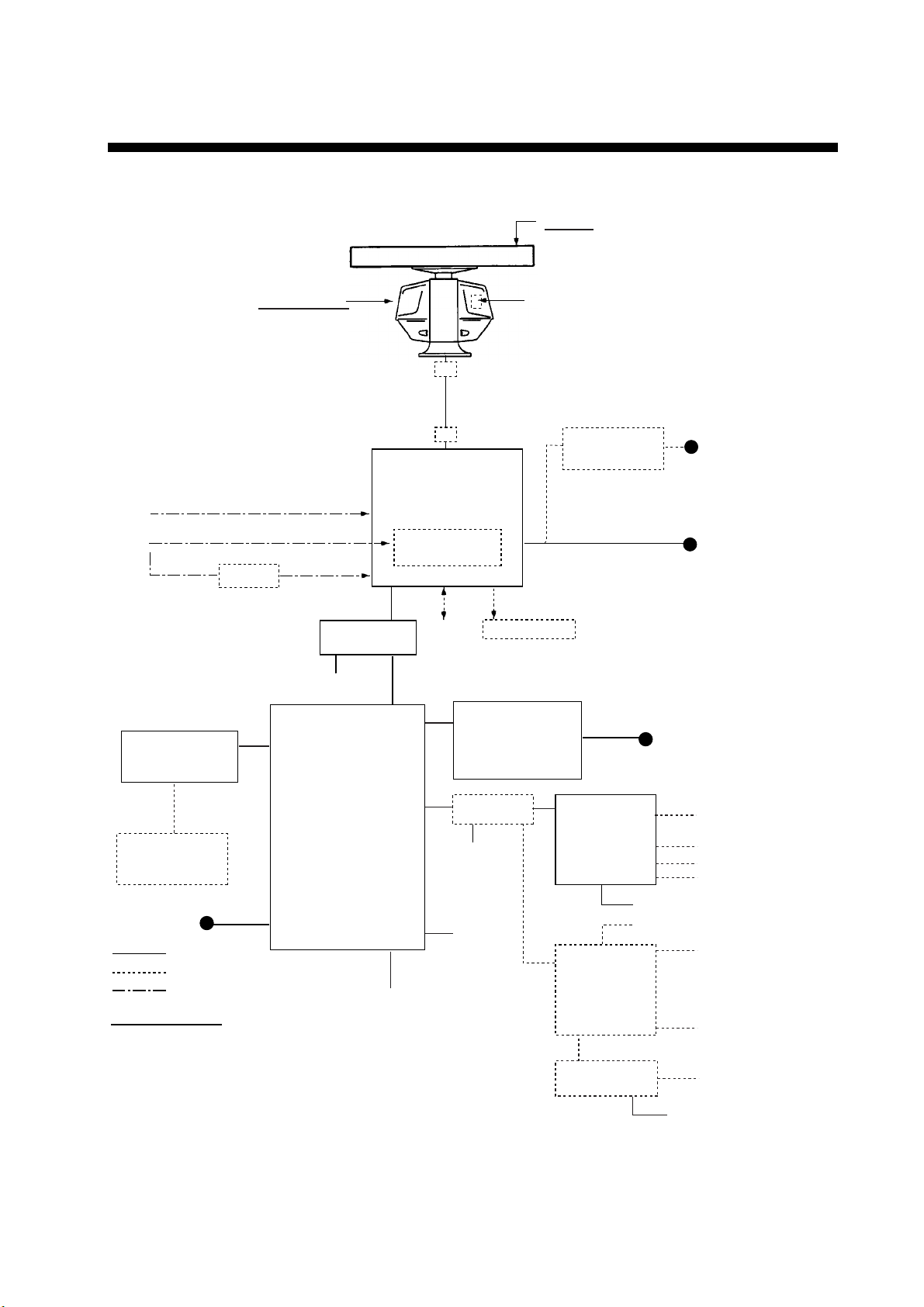
System Configuration
FCR-2117(-BB,-D)/2127(-BB,-D)/2817(-D)/2827(-D)
ANTENNA UNIT
Radiator
XN-20AF (6 ft)
XN-24AF (8 ft)
Transceiver
RSB-096-078
RSB-097-078
RSB-096-079
RSB-097-079
Heading Sensor (IEC-61162-2)
Gyrocompass
AD-100
CONTROL UNIT
RCU-020 or
RCU-015FEA
Switching HUB
HUB-100
100-230 VAC
Junction Box
Junction Box
RADAR
PROCESSOR UNIT
RPU-016
Gyro Converter
GC-10
Alarm
Sub Display
1
FCR-2107-D series
2
FCR-2807-D series
MONITOR UNIT*
MU-190
MU-201CE
MU-231CE
MU-231
Performance Monitor PM-31
Transformer Unit
RU-1803
1
100-230 VAC
2
440 VAC
1
φ
, 50-60 Hz
100-115 VAC/
220-230 VAC
φ
, 50-60 Hz
1
CHART
HUB-100
PROCESSOR UNIT
CONTROL UNIT
EC-1000C
RCU-016
100-230 VAC
: Standard
: Option
: Dockyard supply
PC keyboard
Category of Units
Antenna Unit: Exposed to weather
All other units: Protected from weather
*These monitors have been approved by the IMO, MU-190,
MU-201CE for CAT 2C and CAT 2HC, MU-231CE, MU-231
for CAT 1C and CAT 1HC. If a different monitor is to be used, its
effective diameter must meet the applicable Category requirements:
CAT 1C and CAT 1HC: effective diameter 320 mm or higher
CAT 2C and CAT 2HC: effective diameter 250 mm or higher
For installation, operation and viewing distance of other monitor, see
its manuals.
100-230 VAC
VDR or
Ext. Display
LAN ADAPTER
EC-1010
24 VDC
24 VDC
LAN ADAPTER
EC-1010
B ADAPTER
EPFS
LOG
AIS
ALARM
EPFS
ALARM
ALARM
24 VDC
xvii
Page 20

System Configuration
FCR-2137S(-BB,-D)/2837S(-D)
Radiator
SN30AF/
SN36AF
Performance Monitor
PM-51
POWER SUPPLY
UNIT PSU-007
220 VAC, 3φ, 60 Hz
200 VAC, 3φ, 50 Hz
440 VAC, 3φ, 60 Hz
380 VAC, 3φφ, 50 Hz
For HSC spec
220 VAC, 3φ, 50 Hz
220 VAC, 3φ, 60 Hz
440 VAC, 3φ, 60 Hz
110 VAC, 3φ,
60 Hz
220 VAC, 3φ,
50 Hz
440 VAC, 3φ,
50 Hz
Heading Sensor (IEC-61162-2)
Gyrocompass
RU-5693
RU-6522
RU-5466-1
AD-100
Junction Box
Junction Box
RADAR
PROCESSOR UNIT
RPU-016
Gyro Converter
GC-10
Chassis
RSB-098/099
RSB-100/101/102 (for HSC)
ANTENNA UNIT
Transformer Unit
RU-1803
440 VAC
1φ, 50-60 Hz
100-115 VAC/
220-230 VAC
φ
, 50-60 Hz
1
Switching HUB
HUB-100
100-230VAC
Alarm
1
FCR-2107-D series
2
FCR-2807-D series
MOPNTOR UNIT*
MU-190
CONTROL UNIT
RCU-020 or
RCU-015FEA
CHART
PROCESSOR UNIT
CONTROL UNIT
RCU-016
100-230 VAC
: Standard
: Option
: Dockyard supply
Category of Units
Antenna Unit: Exposed to weather
All other units: Protected from weather
*These monitors have been approved by the IMO, MU-190,
MU-201CE for CAT 2C and CAT 2HC, MU-231CE, MU-231
for CAT 1C and CAT 1HC. If a different monitor is to be used, its
effective diameter must meet the applicable Category requirements:
CAT 1C and CAT 1HC: effective diameter 320 mm or higher
CAT 2C and CAT 2HC: effective diameter 250 mm or higher
For installation, operation and viewing distance of other monitor, see
its manuals.
EC-1000C
PC keyboard
100-230VAC
MU-201CE
MU-231CE
MU-231
HUB-100
VDR or
Ext. Display
Sub Display
1
2
LAN ADAPTER
EC-1010
24VDC
24VDC
LAN ADAPTER
EC-1010
B ADAPTER
100-230 VAC
EPFS
LOG
AIS
ALARM
EPFS
ALARM
ALARM
24 VDC
xviii
Page 21
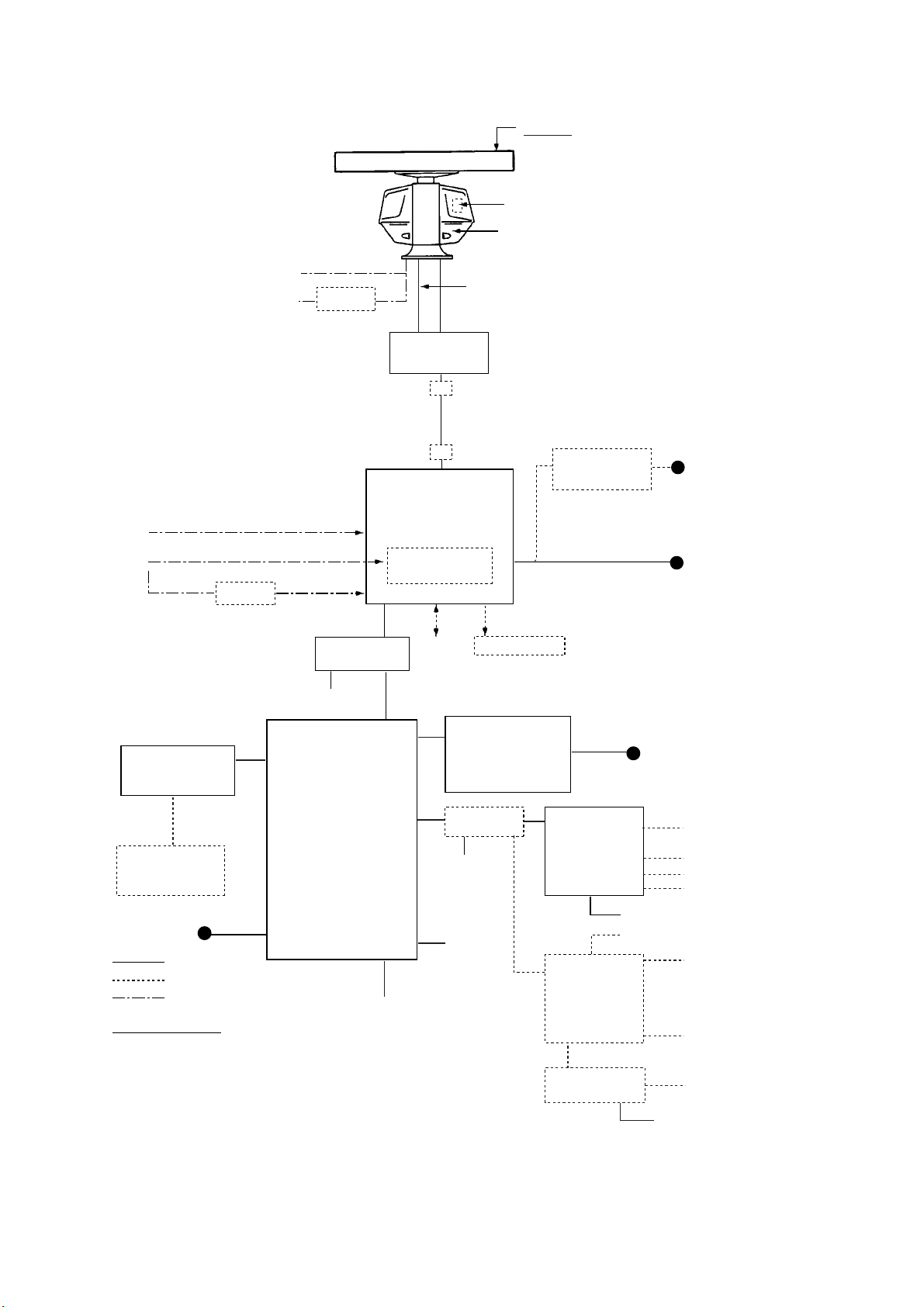
FCR-2827W(-D)
System Configuration
Power for De-icer
AC100V, 1φ, 50/60 Hz
AC100/115/220/230V
1φ, 50/60 Hz
Heading Sensor (IEC-61162-2)
Gyrocompass
AD-100
ANTENNA UNIT
RU-3305
TRANSCEIVER UNIT
PROCESSOR UNIT
Gyro Converter
RTR-081
RADAR
RPU-016
GC-10
Performance Monitor PM-31
Scanner RSB-103
Waveguide
WRJ-9 or FR-9
Junction Box
Junction Box
Radiator
XN-20AF (6 ft)
XN-24AF (8 ft)
Transformer Unit
RU-1803
440 VAC
φ
, 50-60 Hz
1
100-115 VAC/
220-230 VAC
φ
, 50-60 Hz
1
Switching HUB
HUB-100
100-230 VAC
Alarm
# FCR-2807-D series
MONITOR UNIT*
MU-231CE
CONTROL UNIT
MU-231#
RCU-020 or
RCU-015FEA
CHART
HUB-100
PROCESSOR UNIT
CONTROL UNIT
EC-1000C
RCU-016
100-230 VAC
: Standard
: Option
: Dockyard supply
PC keyboard
Category of Units
Antenna Unit: Exposed to weather
All other units: Protected from weather
*These monitors have been approved by the IMO, CAT 1C and CAT
1HC. If a different monitor is to be used, its effective diameter must
meet the applicable Category requirements:
CAT 1C and CAT 1HC: effective diameter 320 mm or higher
CAT 2C and CAT 2HC: effective diameter 250 mm or higher
For installation, operation and viewing distance of other monitor, see
its manuals.
100-230 VAC
VDR or
Ext. Display
Sub Display
LAN ADAPTER
EC-1010
24 VDC
24 VDC
LAN ADAPTER
EC-1010
B ADAPTER
100-230 VAC
EPFS
LOG
AIS
ALARM
EPFS
ALARM
ALARM
24 VDC
xix
Page 22
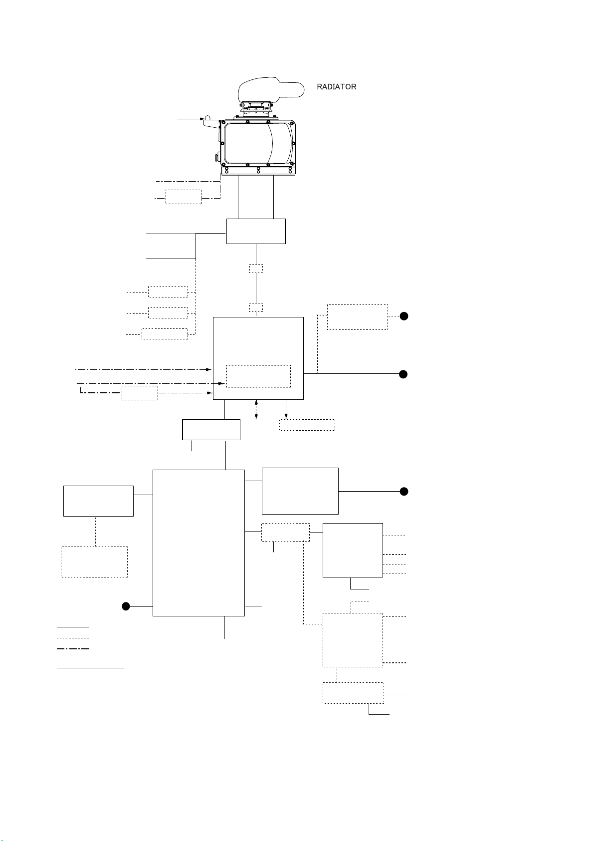
System Configuration
FCR-2837SW(-D)
Performance
Monitor PM-51
Power for De-icer
AC100V, 1φ, 50/60 Hz
AC100/115/220/230V
1φ, 50/60 Hz
RU-3305
SN30AF/SN36AF
RSB104
RSB105
Coaxial Cable CX-20DF
or
Waveguide WRJ-3
AC220V, 3φ, 60Hz
AC200V, 3φ, 50Hz
AC440V, 3φ, 60Hz
AC380V, 3φ, 50Hz
AC110V, 3φ,
60 Hz
AC220V, 3φ,
50 Hz
AC 440V, 3φ,
50 Hz
Heading Sensor (IEC-61162-2)
Gyrocompass
CONTROL UNIT
RCU-020 or
RCU-015FEA
RU-5693
RU-6522
RU-5466-1
AD-100
Switching HUB
HUB-100
100-230VAC
TRANSCEIVER UNIT
RTR-082
Junction Box
Junction Box
RADAR
PROCESSOR UNIT
RPU-016
Gyro Converter
GC-10
Alarm
# FCR-2807-D series
MONITOR UNIT*
MU-231CE
MU-231#
Sub Display
Transformer Unit
RU-1803
440 VAC
1φ, 50-60 Hz
100-115 VAC/
220-230 VAC
φ
, 50-60 Hz
1
100-230 VAC
CHART
PROCESSOR UNIT
CONTROL UNIT
RCU-016
100-230 VAC
: Standard
: Option
: Dockyard supply
Category of Units
Antenna Unit: Exposed to weather
All other units: Protected from weather
*These monitors have been approved by the IMO, CAT 1C and CAT
1HC. If a different monitor is to be used, its effective diameter must
meet the applicable Category requirements:
CAT 1C and CAT 1HC: effective diameter 320 mm or higher
CAT 2C and CAT 2HC: effective diameter 250 mm or higher
For installation, operation and viewing distance of other monitor, see
its manuals.
EC-1000C
PC keyboard
HUB-100
100-230VAC
VDR or
Ext. Display
xx
LAN ADAPTER
EC-1010
24VDC
LAN ADAPTER
EC-1010
B ADAPTER
EPFS
LOG
AIS
ALARM
24VDC
EPFS
ALARM
ALARM
24 VDC
Page 23
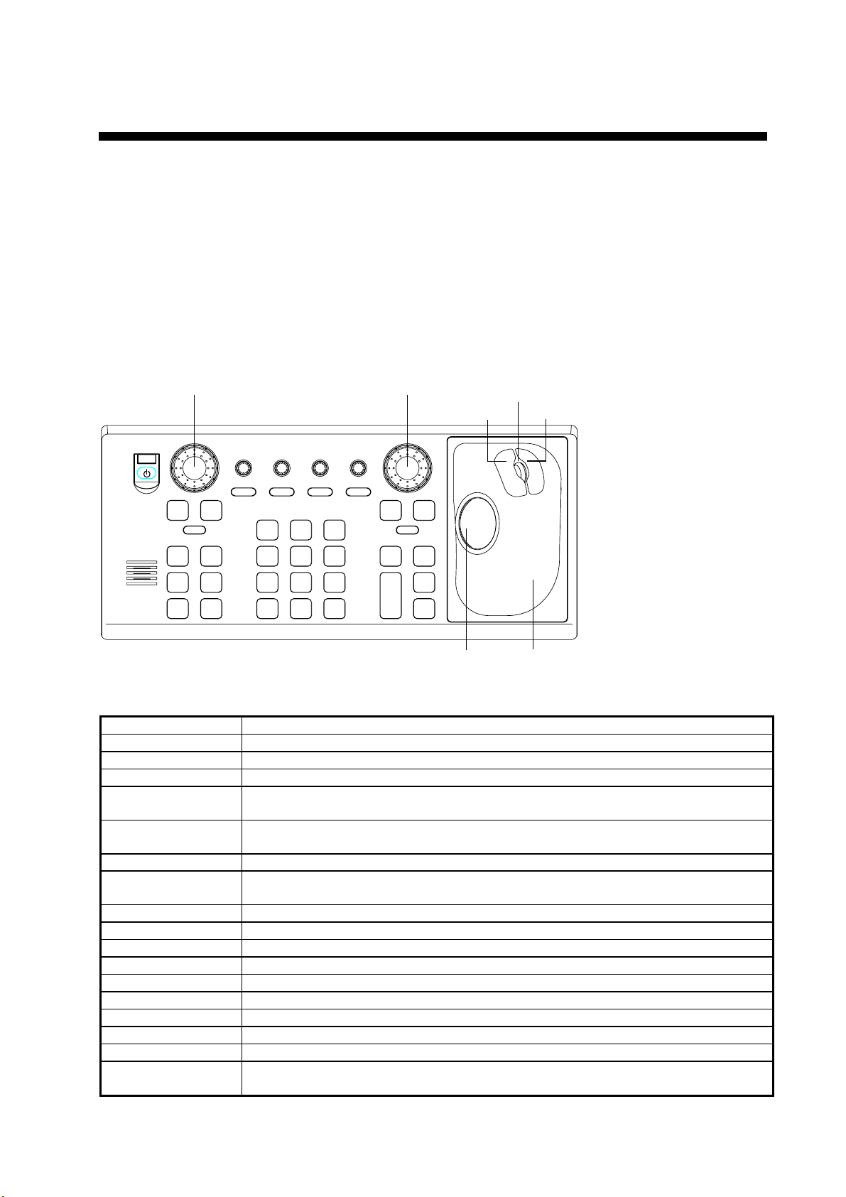
1. Operational Overview
1.1 Units of the System
1.1.1 Control units
Two types of control units are available: Control Unit RCU-020 (full keyboard) and Control Unit RCU-015 (palm
control).
Control unit RCU-020
The Control Unit RCU-020 consists of a keyboard and a trackball module (trackball, scrollwheel and left and right
buttons). The trackball module functions like a mouse; the user rolls the trackball and operates the left and right
buttons and the scrollwheel to access functions.
EBL rotary control VRM rotary control
Left button Right button
Scrollwheel
A/C SEAA/C RAIN
OFFF2ON
EBL
F1
F3 F4
ALARM
ACK
STBY
BRILL
21
HL
EBL
OFF
OFFSET
45
CU/TM
OFF
CENTER
RESET
78
VECTOR
VECTOR
TIME
MODE
0
CANCEL
TX
TRAILS
BRILL
3
MODE
6
INDEX
LINE
9
TARGET
LIST
ENTER
MARK
GAIN
OFF
MENU
RANGE
ON
VRM
ACQ
TARGET
+
DATA
TARGET
-
CANCEL
Trackball
Trackball
module
Control unit RCU-020 (full keyboard)
Key Description
POWER Turns the system on/off. (This control does not switch the display on/off.)
BRILL Adjusts display brilliance. (FURUNO monitor only)
VRM rotary encoder Adjust active VRM.
VRM ON
Activates and displays VRM 1 if none is displayed or VRM2 is active.
Activates and displays VRM 2 if VRM1 is active.
VRM OFF
Inactivates and erases VRM 1 if both VRMs are displayed.
Inactivates and erases VRM 2 if VRM1 is active.
EBL rotary encoder Adjusts active EBL.
EBL ON
Activates and displays EBL1 if none is displayed or EBL 2 is active.
Activates and displays EBL 2 if EBL1 is active.
F1 – F4 User programmable macro keys.
ALARM ACK Alarm acknowledgement for alerts generated by chart, navigation or steering calculation.
STBY TX Toggles radar between standby and TX.
GAIN Adjusts radar gain.
A/C RAIN Reduces rain clutter.
A/C SEA Reduces sea clutter.
HL OFF Temporarily erases heading line.
EBL OFFSET Shifts EBL point of origin/returns point of origin to screen center.
MODE Selects presentation mode.
OFF CENTER Locates own ship on-screen position where desired; returns own ship position to screen
center.
1-1
Page 24
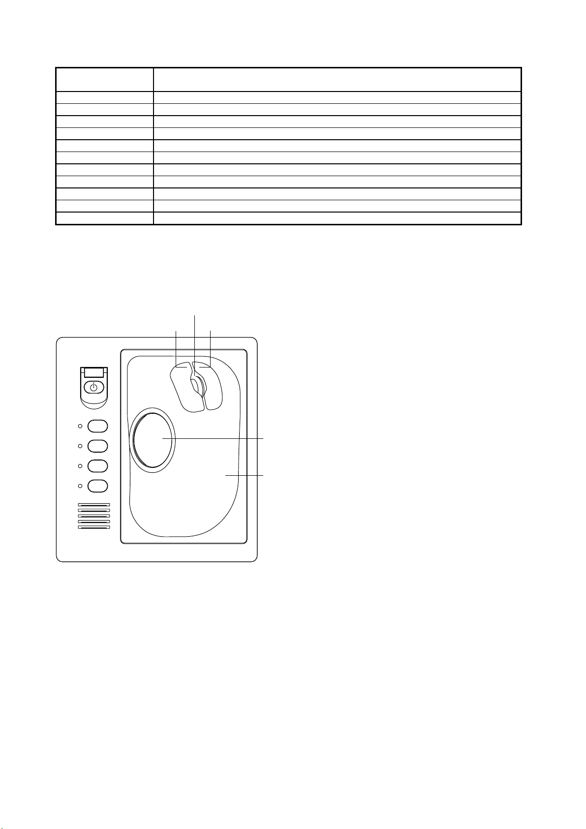
1. Operational Overview
CU/TM RESET In the true motion mode, own ship is shifted 75% of the display radius in the stern
direction. In the course-up mode, the heading line is returned to 0°.
INDEX LINE Enables/disables parallel index lines.
VECTOR TIME Sets vector time (length) for TT (TT).
VECTOR MODE Selects vector mode, true or relative.
TARGET LIST Display TT AIS target list.
CANCEL TRAILS Sets echo trail time. Also functions to cancel data input.
ENTER MARK Terminate input in menu; display MARK dialog box.
MENU Opens/closes main menu.
RANGE Selects radar range.
ACQ Acquires trackball-selected TT.
TARGET DATA Displays data for trackball-selected TT and AIS.
TARGET CANCEL Cancels tracking on trackball-selected TT and AIS.
Control unit RCU-015
The Control Unit RCU-015 has a power switch, trackball module (trackball, scrollwheel and left and right mouse
buttons) and four user-programmable function keys. The trackball module functions like a mouse; the user rolls the
trackball and operates the left and right buttons and the scrollwheel to access functions.
Scrollwheel
Left button Right button
F1
F2
F3
F4
Trackball
Trackball
Module
1-2
Page 25

1. Operational Overview
1.1.2 Chart processor unit
The chart processor unit is responsible for the loading,
storing, updating and processing of electronic sea
charts, with the DVD-ROM drive or floppy disk drive.
The DVD-ROM and floppy disk drives are behind the
lid on the front panel.
Note: Do not operate the ECDIS with a media
(FD/CD/DVD) inserted in its drive, to prevent damage
DVD-ROM
drive
Floppy dIsk
drive
to the drive and media. Remove media from its drive
after usage. Insert media only to do operations such as
backing up data, updating charts, and the like. After
completion, remove the media from its drive and store
it in its case, BEFORE using the ECDIS. Store media
out of direct sunlight, in a place where temperature and
humidity are moderate and stable.
1.2 How to Turn the Power On/Off
Normally, leave the power switch at the rear of the chart processor on and control power on/off with the POWER
key on a control unit. Note that the display unit is powered independently.
After power is applied, the Windows program starts up and about one minute later the bearing scale appears. The
radar then goes into three minutes of warm-up time to warm the magnetron, which transmits radar pulses. The timer
counts the time remaining for warm-up. When the timer has reached 0:00, the indication "ST-BY" appears at the
screen center, meaning the radar is now ready to transmit pulses.
In the stand-by condition, markers, rings, map, charts, etc. are not shown. Further, neither TT nor AIS is active.
If the power is reapplied after the equipment was in the ECDIS mode, Windows starts up and about two minutes
later the ECDIS display appears.
Parameters set on the menus are stored in a non-volatile memory (hard disk) and are preserved when the power is
turned off.
Note: If the ambient temperature is less than 0°C (32°F) when the power is applied, nothing appears on the display.
This is because the heater is warming the chart processor unit. The display appears in approx. 10 minutes.
Transmitter ON
After the power is turned on and the magnetron has warmed
up, ST-BY appears at the screen center, meaning the radar is
ready to transmit radar pulses. You can transmit by pushing
the STBY/TX key on the full keyboard, or use the trackball
to select the TX STBY box at the bottom left corner of the
display then push the left button. The label at the left-hand
side of the guidance area at the bottom right corner of the
screen changes from TX to STBY.
The radar is initially set to previously used range and pulse
length. Other settings such as brilliance levels, VRMs, EBLs
and menu option selections are also set to previous settings.
TX
STBY
TX STBY box
STBY
/
Guidance
box
The STBY/TX key (or TX STBY box) toggles the radar between STBY and TRANSMIT state. The antenna stops
in stand-by and rotates in transmit. The magnetron ages with time resulting in a reduction of output power.
Therefore, it is highly recommended that the radar be set to stand-by when not used for an extended period of time.
1-3
Page 26

1. Operational Overview
Picture freeze
If the picture freezes the picture is not updated. 30 seconds after the picture freezes, the buzzer sounds, the ALARM
ACK key blinks and alarm contact signal is output. Reset the power to restore normal operation.
How to stop antenna rotation
Antenna rotation can be stopped. One method is to turn off the antenna switch on the radar. The other method is to
stop rotation from the menu. For how to stop rotation from the menu, see the installation manual.
About on-screen boxes and indications
The on-screen boxes, like the TX STBY box, provide for adjustment of the item that appears on their labels. Some
indications also function to provide adjustment of a specific function. When you put the cursor inside a box or on an
indication, the color of the label in the box or the indication changes (example: yellow to green). This indicates that
the box or indication is correctly selected. Then, you can change setting by pushing the left button.
1.3 Monitor Brilliance
The brilliance of the entire screen should be adjusted according to lighting conditions. Monitor brilliance should be
adjusted before adjusting relative brilliance levels on the BRILL menu.
Note: The brilliance of a commercial monitor cannot be adjusted from the radar. See the owner’s manual of the
commercial monitor for how to adjust its brilliance.
How to adjust brilliance with the keyboard-equipped control unit
Operate the BRILL control to adjust brilliance. Turn it clockwise to increase brilliance; counterclockwise to
decrease brilliance. Watch the BRILL box (see illustration below) to know current brilliance level.
How to adjust brilliance with the trackball
1. Use the trackball to place the arrow on the brilliance level indicator in the BRILL box at the bottom left corner
of the screen.
Brilliance level
Put arrow inside box to
adjust screen brilliance.
BRILL 1
BRILL box
2. Spin the scrollwheel downward to increase brilliance or spin it upward to decrease brilliance. The length of the
brilliance bar increases or decreases with operation of the scrollwheel.
Note: If nothing appears on the screen at power-up when using Control Unit RCU-015 (palm control) or when the
radar is in stand-by, push and hold down any key except the power switch for four seconds to automatically set up
for medium display brilliance.
Brilliance color set no.
16/16
1-4
Page 27

1. Operational Overview
1.4 Menu Operation
There are two main menus, radar/chart radar and ECDIS, and the one currently available depends on operating
mode. You can access the main menu from the full keyboard or by using the trackball. In later sections only the
procedure for operation by trackball is given. In the example below the menu operating procedure for operation on
the radar/chart radar main menu is presented.
1. Do one of the following depending on the control
unit you are using.
• Control unit RCU-020: Push the MENU key
to show the Main menu.
• Control unit RCU-015 (or RCU-020): Use the
trackball to select the MENU box at the right
side of the screen then push the left button to
show the Main menu, shown left.
2. Use the trackball to select desired menu then push
the scrollwheel to open the menu selected. For
example, select Picture to show the PICTURE
dialog box, shown left.
3. Use the trackball to put the cursor on the setting of
the item you wish to change. The setting changes
color to indicate it is selected. (The color depends on
the color arrangement in use.)
4. Spin the scrollwheel to select setting desired then
push it or the left button to confirm setting.
5. Push the right button to close the menu. (Several
pushes may be necessary depending on the menu
Main menu PICTURE dialog box
used. In some cases you will click the Close window
button (X) at the top right corner on the menu.)
Note: Hereafter, for sake of brevity, we state "push the
scrollwheel" in cases where you can push either it or the
left button.
How to enter data
Alphanumeric data can be changed by selecting it with the cursor then pushing the left button. (This action also
displays minimum and maximum values beside the input field.) Spin the scrollwheel to select value then push it to
confirm setting. (Alphanumeric data may also be entered directly from the keyboard-equipped control unit.)
To change a specific alphanumeric character, use the trackball to put the cursor to the left of the digit or character
that you want to change and spin the scrollwheel to select appropriate character.
How to change co-ordinate polarity (available in the ECDIS mode)
By clicking co-ordinate polarity
1. Put the cursor before the co-ordinate (N, S, E, W) then push the left button.
2. Spin the scrollwheel to select desired polarity then push the scrollwheel.
By choosing polarity from drop-down menu
1. Put the cursor inside the input window.
2. Push the right button to show the following menu.
1-5
Page 28
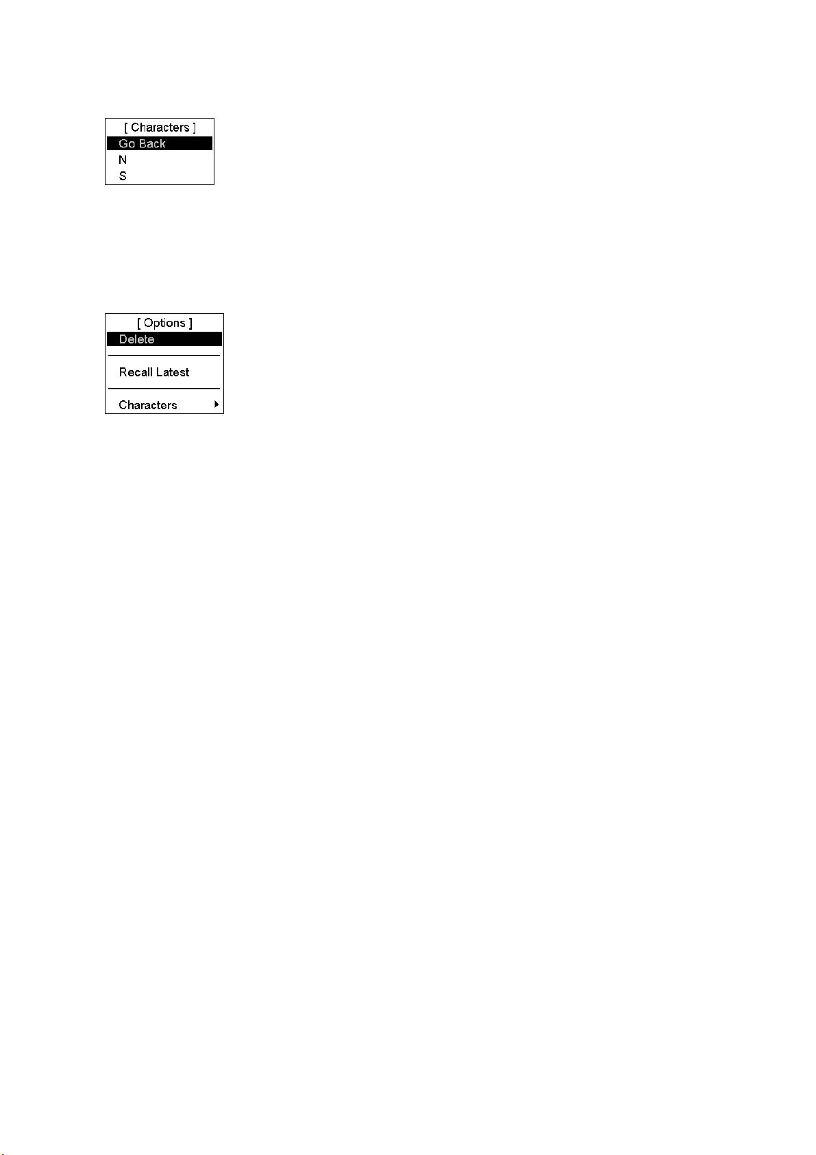
1. Operational Overview
3. Select Characters then push the left button. Your screen should now look something like the one below. (In case
of longitude, E and W replace N and S.)
4. Spin the scrollwheel to select appropriate polarity then push the scrollwheel. The polarity is changed and the
window is closed.
How to delete a character
A character can be deleted from a text/numeric input field as follows:
1. Put the cursor to the right of the digit you want to delete then push the right button.
2. Delete is selected; push the scrollwheel to delete the alphanumeric selected. The character is deleted and the
window is closed.
1-6
Page 29

1. Operational Overview
1.5 The Trackball Module
The trackball module, as shown on pages 1-1 and 1-2, consists of the trackball, right and left mouse buttons and the
scrollwheel.
1.5.1 The scrollwheel
How to control items with the scrollwheel
Selections can be made on the screen by pointing on the screen with the cursor then scrolling various options with
the scrollwheel. When you put the cursor on text or numeric, it turns green, purple or blue (depending on Palette in
use) to indicate that the scrollwheel can be used to scroll options or change value. Confirm your selection by
pushing the scrollwheel.
The following items can be adjusted directly on the screen in the ECDIS mode.
(1) Presentation mode
(2) ECDIS mode
(3) Display scale
(4) Chart only switch
(5) Name of display settings (DspBase, PartStd, Std, Other, AllOther)*
(1) (2) (3) (4) (5)
Operational status icon
(WT)
Rotates to confirm
system is working.
Information
area
Electronic chart area
*DspBase: When no options are checked on Standard page.
PartStd: When some of options (not all) are checked on Standard page.
Std: When all options are checked on Standard page and no options are
checked on Other1/Other 2 pages.
Other: When all options are checked on Standard page and some options
(not all) are checked on Other1/Other2 pages.
AllOther: When all options are checked on Standard page and all options are checked
on Other1/Other2 pages.
Mouse functions area
(Current function of left button,
scrollwheel, right button)
The procedure below shows you how to change the presentation mode from North Up TM to Course Up RM.
1. Put the cursor on the text at the location shown by "1." in the figure above, and the color of the text changes
from current color to green.
2. Use the scrollwheel to scroll options until Course Up RM appears. As you scroll, the color of the text changes
to magenta, blue or green depending on the Palette in use.
3. Push the scrollwheel to confirm your selection, and the color of the text becomes green. When you move the
cursor away from the text, the color of the text returns to its original color.
1-7
Page 30
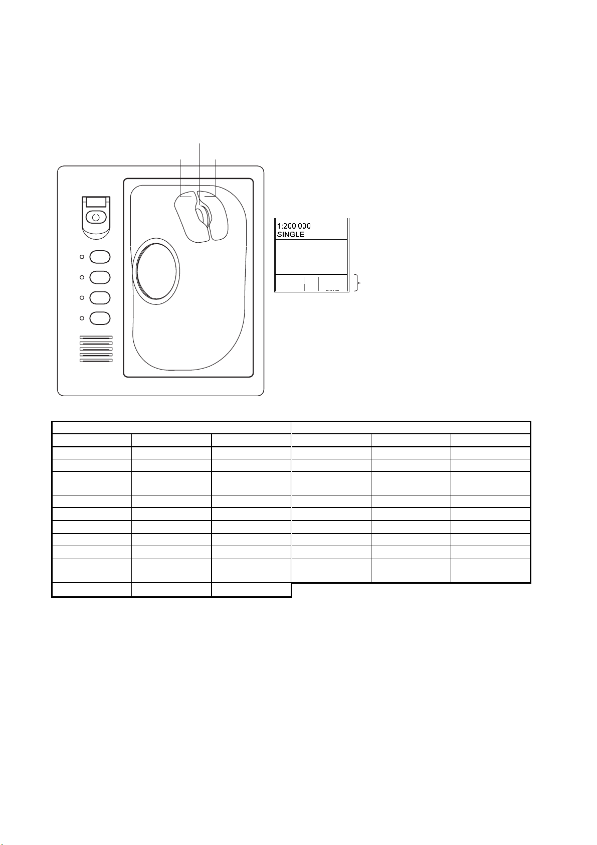
1. Operational Overview
1.5.2 How to call menus and functions by the mouse buttons
The buttons can be used to call menus or functions on the display. At the lower right corner of the display the mouse
functions area displays available function or menu name, as shown in the figure below. Spin the scrollwheel to
choose menu or function desired, then push the left button, scrollwheel or right button as appropriate to access the
menu or function desired. Available menus and functions depend on cursor location
Scrollwheel
Left button Right button
xx.xx xx.xx
F1
F2
F3
F4
Using the functions shown in the figure above
as an example, the available functions with the
mouse are:
Menu
Info Chart
Menu
Mouse functions area
- "Menu" by pushing left button
- "Info" by pushing scrollwheel
- "Chart Menu" by pushing right button
Radar and Chart Radar modes ECDIS mode
Left button Scrollwheel Right button Left button Scrollwheel Right button
Menu Info Chart Menu*1 Menu Info Chart Menu
Range- Info Range+ Range- Info Range+
TM/CU Reset
Info Ship Offcenter TM/CU Reset Info Ship Offcenter
(Note 1)
Event Info MOB Event Info MOB
⎯
Info Cursor Menu
Ref Mark Info
Tgt Acquire Info
⎯
Chart Display
Info Nav Marks Chart Display Info Standard Display
Info (Note 2) Primary Display
(Note 2)
Symbol Display Info
⎯
Tgt Cancel /L=All
(Note 2)
⎯
⎯
Set Chart Center Info Activate Scroll
Show Value Info Nav Marks
Symbol Display Info
Info Cursor Menu
⎯
*1 No indication in radar mode
Note 1: "-" shown when presentation mode is other than North-up or Course-up.
Note 2: Not shown in radar mode.
1-8
Page 31

1. Operational Overview
1.6 Operation Modes
This chart radar has three modes:
• The radar mode display looks like the traditional radar display.
• The chart radar display combines radar with chart. (The chart radar mode is optional, and it does not meet the
criteria for navigation aid for Japanese flag vessels as defined by Japanese law.)
• The ECIDS display shows ECDIS chart.
1.6.1 When chart radar mode can be used
There are some limitations when using the system in the "chart radar" mode. Below are the conditions where the
"chart radar" mode may be used:
1) Range in "chart radar" mode is between 0.125 nm and 24 nm.
• If you change from "radar" mode to "chart radar" mode when the range is 24 nm or less, the range is not
changed. And if range is more than 24 nm the system automatically selects the 24 nm range.
2) Presentation mode is "course-up RM", "north-up RM" and "north-up TM" in "chart radar" mode.
• If you change from "radar" mode to "chart radar" mode when the presentation mode is "head-up RM", the
system automatically changes the presentation mode to "north-up TM".
1.6.2 How to switch modes
At the top of the screen are the operating mode boxes, Radar, Chart Radar, and in the ECIDS mode, ECDIS. To
switch modes put the cursor in the operating mode box then push the left button until desired mode name is
displayed in the box.
.
1-9
Page 32

1. Operational Overview
1.7 How to Configure Hot Keys F1-F4
Hot keys F1-F4 are provided to call a desired function/menu when pushed.
You can select desired function/menu from a predefined list. To select desired function/menu for each key, do the
following:
1. Spin the scrollwheel until Menu/Info/Chart Menu appears in
the guidance area.
2. Push the left button.
3. Spin the scrollwheel to select Initial Settings then push the
scrollwheel.
4. Put the cursor on the triangle in the menu to show the Initial
Settings menu.
5. Spin the scrollwheel to select Function keys, then push the
scrollwheel. The menu shown right appears.
6. Check Enable changes.
7. Put the cursor on the box for F1, F2, F3 or F4 as appropriate
and spin the scrollwheel to select desired function or menu.
Enable changes
Item Content
Radar, Radar Chart Mode
ALARM ACK Acknowledge alarm generated by this chart radar.
CHART MENU Open chart menu.
CHART DISPLAY Open chart setting dialog box.
SENSORS Open sensor setting dialog box.
MENU Open main menu.
STANDARD DISPLAY Restore standard display.
SYMBOL DISPLAY Show symbol display dialog box.
RANGE+ Shrink chart.
RANGE- Enlarge chart.
INITIAL SETTINGS Show initial settings dialog box.
ECDIS Mode
ALARM ACK Acknowledge alarm generated by this chart radar.
CHART MENU Open chart menu.
CHART DISPLAY Open chart setting dialog box.
SENSORS Open sensor setting dialog box.
MENU Open main menu.
STANDARD DISPLAY Restore standard display.
SYMBOL DISPLAY Show symbol display dialog box.
TM/CU RESET Return own ship to screen center in true motion and course-up modes.
TOGGLE SHIP CENTER Toggle own ship position between screen center and cursor location.
RANGE+ Shrink chart.
RANGE- Enlarge chart.
INITIAL SETTINGS Show initial settings dialog box.
How to activate a menu or function with a hot key
Push the function key corresponding to the menu or function you wish to activate.
1-10
Page 33

1. Operational Overview
1.8 Geodetic Datum
This chart radar uses ENC material, produced to standards using WGS-84 datum. Positioning devices connected to
this equipment must work in the WGS-84 datum. IMO require that a chart radar must give an alert if the datum of a
positioning device is not the WGS-84. In practice this is impossible, because the standard used by positioning
devices (IEC 61162, previously NMEA 0183) does not include a datum message. Consequently, the classification
societies only approve a positioning device interfaced with the chart radar where datum cannot be changed (i.e., is
always WGS-84).
Note: The ability to check datum of position is a relatively new feature for position receivers. It was introduced in
standard IEC 61162-1 Ed2, published July 2000. Only an EPFS (for example GPS or DGPS) that has "IEC 61162-1
Ed 2 (2000-7)" indicated in its type approval certificate can support the chart radar to detect datum mismatch.
This system allows the user to change viewed datum. This selection of the datum does not change anything inside
the system for navigation calculation processes or for electronic sea chart display processes. But it changes the
numerical values of positions displayed on the chart radar display into the user-chosen datum. This is very useful,
especially if you like to plot positions from the chart radar on a traditional paper chart.
1.9 Navigation Marks on Chart Radar and ECDIS Modes
If the EBL and VRM cannot be controlled from a control unit, use the NAV Marks dialog box. To show this box,
spin the scrollwheel to show ---/Info/Nav Marks in the guidance box then push the right button.
Set 1 page
REF point: Turn on/off the reference point on the electronic chart.
VRM: Turn on/off the VRM (Variable Range Marker), which is displayed around
the reference point.
EBL: Turn on/off EBL (Electronic Bearing Line), which extends from the reference
point.
Rings: Turn on/off the range rings, which circumscribe the reference point. The ring
interval depends on scale of displayed chart.
Info: Turn on/off numerical information about VRM, EBL and reference point. This
item is not displayed in the radar or radar chart mode.
REF point - Centered: Check to set center for your ship.
Set 2 page
Provides a second set of the items contained in set 1.
1-11
Page 34

1. Operational Overview
1.9.1 EBL operation
With control unit RCU-020
There are two EBLs, No. 1 and No. 2. Each EBL is a straight dashed line extending out from the own ship position
up to the edge of the screen. The long dashed line is the No. 1 EBL and the short dashed one is the No. 2 EBL. Push
the EBL ON key to display either of the EBLs. Successive pushes of the EBL ON key toggle the active EBL
between No. 1 and No. 2. To adjust an EBL, use the EBL rotary encoder, which is above the EBL OFF and EBL
ON keys. The EBLs can be turned on or off from the NAV Marks dialog box by checking or unchecking EBL on
the Set 1 or Set 2 page.
Each EBL carries a range marker, or a short line crossing the EBL at right angles and its distance from the EBL
origin is indicated at the VRM readout whether or not the corresponding VRM is displayed. The range marker
changes its position along the EBL with the rotation of the VRM rotary encoder. The corresponding VRM must be
turned off to use a range marker.
With control unit RCU-015
You have two methods available to adjust the EBL. You can directly enter a numeric value for the EBL on the NAV
Marks dialog box, or you can put the cursor on an EBL, then push and hold down the left button while rotating the
trackball. If you locate the cursor over the intersection of a VRM and an EBL, you can adjust them together, using
the left button and trackball. (Note that this can also be done from the keyboard-equipped control unit.) The EBLs
can be turned on or off from the NAV Marks dialog box by checking or unchecking "EBL" on the Set 1 or Set 2
page.
1.9.2 VRM operation
With control unit RCU-020
There are two VRMs, No. 1 and No. 2, which appear as dashed rings so that you can discriminate them from the
fixed range rings. The two VRMs can be distinguished from each other by different lengths of their dashes. Push the
VRM ON key to display either of the VRMs. Successive pushes of the VRM ON key toggle the active VRM
between No. 1 and No. 2. To adjust a VRM, use the VRM rotary encoder, which is above the VRM OFF and VRM
ON keys.
With control unit RCU-015
You have two methods available to adjust the VRM. You can directly enter a numeric value for the VRM on the
NAV Marks dialog box, or you can put the cursor on the VRM, then push and hold down the left button while
rotating the trackball. If you put the cursor over the intersection of a VRM and an EBL, you can adjust them
together, using the left button and trackball. (Note that this can also be done from the keyboard-equipped control
unit.) The VRMs can be turned on or off from the NAV Marks dialog box by checking or unchecking "VRM" on the
Set 1 or Set 2 page.
1-12
Page 35

1. Operational Overview
1.9.3 How to shift the reference point of EBL and VRM
The reference point, shown on the display with a cross mark (if turned on in the Nav Marks dialog box), is a userspecified location to which measurements of range and bearing are referred. To choose the location for the reference
point, open the Nav Marks dialog box, check REF point, put the cursor at the location desired then push the right
button.
Centered reference point with Variable Range Marker (VRM) and Electronic Bearing Line (EBL)
Reference point off centered with Variable Range Marker (VRM) and Electronic Bearing Line (EBL)
1-13
Page 36

1. Operational Overview
1.10 Ship’s Position
The operator can select navigation sensors to use for navigation and view their current values on the SENSORS
dialog box. For more information about navigation sensors, see Chapter 15.
Note: Availability of sensors to select from the SENSORS dialog box is limited to the position sensors connected to
the system.
1. Put the cursor on the Position field in the information area.
2. Push the right button, and the POSN page automatically appears.
SPD/CRS POSN
NM
DR
kn
DGPS-1st
kn
kn
LORAN
Off
°
kn
3. Select desired navigation sensors. Spin the scrollwheel to select Position sensors (GPS(s)) either Primary or
Secondary then push the scrollwheel.
4. If no Position sensor is selected or no valid position is available, then you can enter position manually, in the
"Deadrec" field.
5. Click the Close window button (X) to close the SENSORS dialog box.
1-14
Page 37

1. Operational Overview
1.11 How to Customize Operation
Several operation items may be customized to suit your needs.
1. Use the trackball to select the MENU box at the right side of the screen then push the left button.
2. Spin the scrollwheel to select Initial Setting.
3. Push the scrollwheel.
4. Put the cursor on the small triangle in the upper left corner of the Initial Settings dialog box to show the Initial
Settings menu. Spin the scrollwheel to select Operation then push the scrollwheel to open the Operation menu.
Operation menu
5. Set each item as appropriate, referring to the table below for details.
6. Push the right button to close the menu.
Item No. Description Options
Key Beep Loudness of key beep when a key
Wheel Drive Select how to cycle data when using
Alarm Level Volume of audio when alarm is
TTG Display Select speed to use in TTG
TTG with VRM Show TTG below VRM box, in
Operation menu items
sequence is correctly done.
the scrollwheel.
generated by the system.
calculation: water speed or ground
speed.
radar and chart radar modes.
Off (no beep), Low, Mid, High
Normal: Cycles numeric data in ascending order and
indication data in clockwise order.
Reverse: Reverse of "Normal".
Off*, Low, Mid, High
(*: radar, chart radar only)
Off (disable TTG feature), ground speed, water speed
Off, VRM1, VRM2, VRM1+VRM2
1-15
Page 38

1. Operational Overview
1.12 Alerts Description
When error is detected, the appropriate alert indication appears (in red or yellow) and the audio alert sounds. Silence
the audio alert with the ALARM ACK key or select the ALARM ACK box then push the left button. The error
indication remains on the display until the reason for the alert is removed.
Alerts description
Message no. Message Alert category Description
100 RadOv No Headline Warning No heading signal
101 RadOv No Azimuth Warning No antenna rotation signal
102 RadOv No Trigger Warning No trigger signal
103 RadOv No Video Warning No video signal
108 Watch Alarm Warning
705 Gyro Error Warning Gyro data is not received correctly.
708 Log Error Warning Log data is not received correctly.
709 Dual-Axis Log (BT) Error Warning Dual axis log data is not received correctly.
710 Echo Sounder Error Warning Echo sounder data is not received correctly.
711 Wind Sensor Error Warning Wind sensor data is not received correctly.
712 Position Eq Error Warning Position equipment data is not received correctly.
738 Datum mismatch Warning
764 LAN fail for LAN-adapter Warning
Watch 0:00 (Watch appears and time count freezes
at 0:00).
Position sensor outputs position another datum as
set in Installation parameters.
Unexpected LAN error. Maybe LAN cable or
HUB broken/disconnected.
771 LAN fail for Radar Warning
860 Safety Contour Alarm Depth is less than the safety contour.
874 Anchor Watch Warning Ship has drifted more than a threshold value.
Refer to section 4.15 TT Alerts for TT alerts, section 5.17 AIS Alerts for AIS alerts.
Unexpected LAN error. Maybe LAN cable
broken/disconnected.
How to output alarm signals
Four ports are provided to output alarm signals to external equipment. Select the port and alarm signals to contact
output. For more information, see the installation manual.
1-16
Page 39

1. Operational Overview
1.13 Charts
S57 ENC ed. 3 vector charts or CM-93 vector charts may be used.
How to load and update charts
Charts can be loaded and updated when the chart radar mode is in use. For more information about how to load and
update charts, see Chapter 7 Vector Chart.
1.14 Route Monitor
A route created by ECDIS can be overlaid on the radar and chart radar pictures. There are two ways to display the
route in this modes:
- Stand-alone mode: Use ECDIS mode-created route
- Route share mode: Use ECDIS route received via an ECDIS unit connected to the network
Stand-alone mode
1. Use the trackball to select the Route selection box at the upper part of the display.
Route: Not selected (Route selection box)
2. Spin the scrollwheel to select desired route for monitoring. Route planning must be done in the ECDIS
mode.
For more information about route planning and monitoring, see Chapter 10 How to Plan Routes and Chapter 11
How to Monitor Routes.
Route share mode
Route cannot be created in this mode. Further, route to monitor cannot be selected. ECDIS mode created route is
displayed however it cannot be selected for monitoring. On an ECDIS unit connected to the network, open the route
from Plan Route. Select Exchange with monitored from the menu, or open the route directly with Monitor route.
Then, the route is displayed on the ECDIS screen as well as radar and chart radar.
Note: To receive route information from an ECDIS unit in the network, that ECDIS must be set up to transfer route
information. For further details, contact your dealer.
1-17
Page 40

1. Operational Overview
1.15 Switching Hub HUB-100
The HUB-100 provides switching for a radar processor and chart processor unit, using an Ethernet interface
(100BASE-TX/10BASE-T). LEDs display link/activity, mode (full-duplex or half-duplex) and collision states. No
operation is required of the user. Simply turn on the AC power source for the Switching Hub to power it.
LED display
The LEDs on the top of the unit light, flash or go off according to equipment state. When the equipment is powered
all LEDs light and go off.
Switching Hub HUB-100
LED status and meaning
LED Status Meaning
Power Lit
Off
Link/Act Lit
Off
Flashing
FDx/Col Lit
Off
Flashing
100M Lit
Off
Equipment powered
Equipment off
Connection with terminal normal
Connection with terminal disconnected
Data TX or RX
Full-duplex
Half-duplex
Collision
100 Mbps connection
10 Mbps connection
1-18
Page 41

2. Radar Operation
2.1 Display Indications
2.1.1 Radar mode
Picture Box
PULSELENGTH Box
ANTENNA Box
PRESENTATION Mode
RANGE Box
NM
3
/ 0.5
Head Up RM
*1
CHART RA X-BAND
PULSE M1
PICTURE 1
IR 2
ES 2
EAV OFF
AUTO
RAIN 3
320
310
300
290
280
270
Acquistion
Zone
No. 1
EBL
260
No. 2 EBL
250
No.1 VRM
240
PI 1
ON
230
°
000.0
T
0.00
BRILL 1
HL
OFF
TX
STB
NM
EBL1
EBL2
220
12/16
> 280.5° T<
241.0° T
No. 2 EBL
TX/STBY Box
HL OFF Box
BRILL, COLOR Box
PI (Index Line) Box
-PI orientation
-PI interval
Radar
330
210
DROP1
90.7°T 0.742NM
REF point
MODE Box
REF point
CCRP
350
340
Heading
Marker
Heading Line
Stern Mark
200
190
Drop Mark data
No. 1 EBL
000
Cursor Position, TTG and R/B to Cursor
GAIN setting
A/C SEA setting
A/C RAIN setting
TUNING setting
000. 0°TSET
010
North Mark
170
180
0. 0knDRIFT
020
030
Cursor
Drop
Mark
No. 2 VRM
150
160
DROP2
°
T NM
No. 2 VRM
No. 1 VRM
w/TTG data
*1
To adjust, put arrow
on setting and left-click.
IR: Interference Rejector
ES: Echo Stretch
EAV: Echo Averaging
AUTO RAIN: Auto rain clutter reduction
TRIAL MANEUVER Box
Gain
Sea MAN
Rain MAN
Tune AUTO
+
040
050
MENU Box
Symb DISP Box
060
+
130
140
00:00
VRM1
>3.682NM<
VRM2
5.221NM
120
WATCH Box
Set Box,
DRIFT Box
80
0
0
0
34°40. 649 N
135°18. 303 E
TTG 312.3°R
00:11 1.864
TRIAL OFF
MENU
Symb
DISP
070
080
090
100
110
Watch
11:28
TGT
LIST
AZ1
AZ2
True Trail
01:00
TM
Res
ALM
ACK
Alarm
acknowledge
HDG 046.0°
SPD (CALC) 17.3 kn
SB (POSN) 0.8 kn
COG (POSN) 048.7°
SOG (POSN) 17.4 kn
59°54.097'N
°
59.582'E
024
WGS84
NM
DGPS
Route: HELSINKI
Plan Speed 30.0 kn
Plan 202.9°
Route 217.9°
CH LIM 195 m
Off track < 0.9 NM
Outside channel
To WPT
Dist WOP NM
Time
Next WP
Next
Tur n rad NM
Turn rate °/min
UserChart Notes
10 APR 2009 10:28
LOCAL (UTC + 03:00)
59°52.031'N
135
+
5.476 NM 91.5
AUTO
TT > AIS
MAN
T VECT(G) 5 min
Predictor 30 s
PASTPOSN T 12min
CPA 10.0NM 30min
CPA AUTO act FILT
Lost TGT alarm FILT
SINGLE xx.xx xx.xx
Range - Info Range +
Guidance area
(Current button,
scrollwheel function)
System Status
(Sector rotates clockwise
to confirm system is working.)
Heading
°
Speed
Transversal speed
Course over ground
Speed over ground
Position
Datum
Source of Position*
Route Data Box
WPT Data Box
°
User Chart, Notes Box
Date, Time Box
°
45.365'E
Cursor Data
°
DISP
Box
ALL
Target List Box
Acquisition zone setting
T arget Trail setting
True motion reset
Alert Box
Viewing distance
The nominal viewing distances for the radar display units are as follows:
- MU-190: 1020 mm
- MU-231: 1200 mm
- MU-201CE: 1080 mm
- MU-231CE: 1200 mm
2-1
Page 42

2. Radar Operation
2.1.2 Chart radar mode
MODE Box
(see section 1.6)
Chart database information (see section 2.34.2)
000
DspBase
010
NM
3
/ 0.5
Course Up RM
CHART RA X-BAND
PULSE M1
PICTURE 1
IR 2
ES 2
EAV OFF
AUTO
RAIN 3
310
Chart
REF point
Radar
CCRP
330
340
350
320
300
290
280
270
260
250
Chart
Priority
Coast
240
Line Only
PI 1
ON
230
°
000.0
T
0.00
BRILL 1
HL
OFF
TX
STB
NM
EBL1
EBL2
220
12/16
> 280.5° T<
241.0° T
210
200
DROP1
91.7 °T 0.765NM
190
180
170
Coast Line Only Box (see section 2.34.3)
020
160
000. 0°TSET
0. 0knDRIFT
030
150
DROP2
°T NM
Gain
Sea MAN
Rain MAN
Tune AUTO
040
050
+
130
140
00:00
VRM1
>3.682NM<
VRM2
5.221NM
+
135°18. 303 E
TTG 312.3°R
00:11 1.864
060
070
110
120
AZ1
AZ2
True Trail
80
0
0
0
34°40. 649 N
TRIAL OFF
MENU
Symb
DISP
080
090
100
Chart
Status
Chart
DISP
Watch
11:28
TGT
LIST
01:00
TM
Res
ALM
ACK
HDG 046.0°
SPD (CALC) 17.3 kn
SB (POSN) 0.8 kn
COG (POSN) 048.7°
SOG (POSN) 17.4 kn
59°54.097'N
024
°
59.582'E
WGS84
NM
DGPS
Route: HELSINKI
Plan Speed 30.0 kn
Plan 202.9°
Route 217.9°
CH LIM 195 m
Off track < 0.9 NM
Outside channel
To W PT
Dist WOP NM
Time
Next WP
Next
Tur n rad NM
Turn rate °/min
UserChart Notes
10 APR 2009 10:28
LOCAL (UTC + 03:00)
59°52.031'N
135
+
5.476 NM 91.5
AUTO
TT > AIS
MAN
T VECT(G) 5 min
Predictor 30 s
PASTPOSN T 12min
CPA 10.0NM 30min
CPA AUTO act FILT
Lost TGT alarm FILT
SINGLE xx.xx xx.xx
Range - Info Range +
°
45.365'E
°
Symb DISP Box
(see section 7.9.5)
°
Chart Status Box
(see section 2.34.4)
°
DISP
ALL
Chart DISP Box
(see section 2.34.1)
Chart Priority Box (see section 2.34.3)
2-2
Page 43

2. Radar Operation
2.2 How to Tune the Receiver
2.2.1 How to select the tuning method
The tuning method can be selected with the TUNE box at the top of the screen.
1. Use the trackball to select the TUNE box (Tune MAN or Tune AUTO) at the top of the screen.
For manual tuning, put arrow inside box to adjust tuning.
Tune AUTO
Tuning method (AUTO or MAN)
TUNE box
2. Push the left button or spin the scrollwheel to display TUNE AUTO or TUNE MAN as appropriate.
3. Push the scrollwheel.
2.2.2 How to initialize tuning
Automatic tuning is initialized during the installation. However, if you feel that automatic tuning is not working
properly try re-initializing it as follows:
1. Left-click the MENU box.
2. Spin the scrollwheel to select Echo then push the scrollwheel.
3. Spin the scrollwheel to select Tune Initialize.
4. Push the scrollwheel to start initialization.
[Echo]
Go Back
2nd Echo Rej
PM
SART
Tune Initialize
2.2.3 Automatic tuning
Select automatic tuning following section 2.2.1 How to select the tuning method. The TUNE box shows TUNE
AUTO.
2.2.4 Manual tuning
1. Use the trackball to select the RANGE box at top left corner then push the left or right button as appropriate to
select the 48-mile range. Push the left button to lower the range; the right button to raise the range.
2. Select manual tuning following the procedure in section 2.2.1 How to select the tuning method.
3. Use the trackball to place the arrow in the tuning bar area in the TUNE box.
4. Spin the scrollwheel to adjust tuning. The best tuning point is where the bar swings maximum. The triangle
below the bar graph shows tuning control position; not the tuning condition.
2-3
Page 44

2. Radar Operation
2.3 How to Set the Heading
With connection of a gyrocompass, ship's heading is displayed at the right side of the screen. If the GYRO readout
looks wrong or the gyro alarm sounds, follow the procedure below to set heading. For more information, see
Chapter 1. Note that the FURUNO SC-60/120 does not require adjustment on the radar.
1. Use the trackball to place the arrow in the HDG value at the top right corner of the screen.
2. Push the right button to open the SENSORS dialog box. Use the arrow buttons to select the SPD/CRS dialog
box.
SENSORS dialog box, SPD/CRS page selected
3. Roll the trackball downward to select Gyro 1or Rate gyro as applicable then push the scrollwheel to place check
mark in box.
Initial setting of gyro1 is not necessary if it outputs serial data. However, if it is of synchro or stepper type, you
will need to set initial gyro value. For how to adjust the gyro value, see the installation manual.
4. Click the Close window button (X) to close the SENSORS dialog box.
2-4
Page 45

2.4 Presentation Modes
2.4.1 Presentation modes
This radar has the following presentation modes in the radar mode:
15. Navigation Sensors
Relative Motion (RM)
Head-up: Unstabilized
Head-up TB: Head-up with compass-stabilized bearing scale (True Bearing) where the bearing scale rotates with
the compass reading.
Course-up: Compass-stabilized relative to ship’s orientation at the time of selecting course-up.
North-up: Compass-stabilized with reference to North.
True Motion (TM)
North-up: Ground or sea stabilized with compass and speed inputs.
Choosing presentation mode by keyboard
Push the MODE key consecutively to select radar presentation mode desired. The PRESENTATION MODE box
shows the current presentation mode.
Choosing presentation mode by trackball
1. Use the trackball to select the PRESENTATION MODE box at the top left corner of the screen.
2. Push the left button to select mode desired.
Loss of gyrocompass signal
When the compass signal is lost, alert "705: Gyro error" or "706: Gyro error" appears. After timeout, the alert
"402: No heading available" appears, the presentation mode automatically becomes head-up, and all TT and AIS
targets are erased. Check the gyro and select the presentation mode with the MODE key or the PRESENTATION
MODE box.
2.4.2 Description of presentation modes
Head-up mode
The head-up mode is a display in which the line connecting own ship and the top of the display indicates own ship’s
heading.
The target pips are painted at their measured distances and in their directions relative to own ship’s heading.
The short line on the bearing scale is the north marker, which indicates heading sensor north. A failure of the
heading sensor input will cause the heading readout to disappear, and the message "No heading available" or "Gyro
error" (message in red) appears at the lower right corner of the screen.
North Marker
Heading Line
When the display is off centered
the heading line appears at 0 degree.
Head-up mode
2-5
Page 46

2. Radar Operation
Course-up mode
The course-up mode is an azimuth stabilized display in which a line connecting the center with the top of the display
indicates own ship’s intended course (namely, own ship’s previous heading just before this mode has been selected).
Target pips are painted at their measured distances and in their directions relative to the intended course, which is
maintained at the 0-degree position. The heading line moves in accordance with ship’s yawing and course change.
This mode is useful for avoiding smearing of picture during course change.
Course-up mode
Head-up TB (True Bearing) mode
Radar echoes are shown in the same way as in the head-up mode. The difference from normal head-up presentation
lies in the orientation of the bearing scale. The bearing scale is heading sensor stabilized. That is, it rotates in
accordance with the heading sensor signal, enabling you to know own ship’s heading at a glance.
This mode is available when the radar is interfaced with a gyro heading sensor. If the gyro heading sensor fails, the
bearing scale returns to the state of head-up mode.
North-up mode
The north-up mode paints target pips at their measured distances and in their true (heading sensor) directions from
own ship, north bearing maintained at the top of the screen. The heading line changes its direction according to the
ship’s heading. Requires heading signal.
If the compass fails, the presentation mode changes to head-up and the north marker disappears. A failure of the
heading sensor input will cause the heading readout to disappear, and the message "No heading available" or "Gyro
error" (message in red) appears at the lower right corner of the screen.
North Marker
Heading Line
2-6
North-up mode
Page 47

15. Navigation Sensors
True motion mode
Own ship and other moving objects move in accordance with their true courses and speed. In ground stabilized TM,
all fixed targets, such as landmasses, appear as stationary echoes. In the sea stabilized TM without set and drift
inputs, the landmass can move on the screen. Note that true motion is not available on the 96 nm range scale. If
COG and SOG (both over the ground) are not available on TM mode, enter the set (tide direction) and drift (tide
speed) manually referring to the Tide Table.
If the position of the CCRP results in a part of the bearing scale not being distinguishable, that part of the bearing
scale is indicated with appropriate reduced detail.
North Marker
Heading Line
A failure of the heading sensor input will cause the heading readout to disappear, and the message "No heading
available" or "Gyro error" (message in red) appears at the lower right corner of the screen.
When own ship reaches a point corresponding to 75% of the radius of the display, own ship position is automatically
reset to a point of 75% radius opposite to the extension of the heading line passing through the display center. You
can also reset the own ship symbol manually by pushing the CU/TM RESET key, or use the trackball to select the
TM Res box at the bottom right corner of the display then push the left button.
North
Heading
line
(a) True motion
is selected
marker
(b) Own ship has reached a
point 75% of display radius
(c) Own ship is automatically
reset to 75% of radius
2-7
Page 48

2. Radar Operation
2.5 How to Input Your Ship's Speed
The Target Tracking (TT) and azimuth stabilized presentation modes require own ship speed input and compass
signal. The speed can be entered from a log (STW) or GPS (SOG), or manually from the menu. Note that FURUNO
GPS Navigator GP-90 provides COG and SOG.
For more information about positioning and Kalman filter operation, see Chapter 15 Navigation Sensors.
2.5.1 Speed selection for SPD and SB (TT, AIS and trails)
The system speed that is used for TT, AIS and trails appears at the upper right corner in fields "SPD" and "SB."
These values are used for:
- Calculation of target CPA/TCPA
- Target past position
- Target trail
Note 1: SPD: Longitudinal speed, SB: Transversal speed, positive value to starboard
Note 2: When the AIS feature is active, MANUAL and REF are not available for selection.
To select system speed "SPD" and "SB", do the following:
1. Put the cursor on the SPD or SB field in the information area then push the left button to show the following
dialog box.
2. Put cursor on Speed source (LOG(BT) in this case) and use scrollwheel to select appropriate source.
2-8
Page 49

15. Navigation Sensors
2.5.2 Speed selection for COG and SOG (navigation)
The system speed that is in use for navigation appears at "COG" and "SOG." These values are used for:
• TTG calculation
• Route Monitoring for ETA calculation
• Kalman filter for position calculation
• Dead reckoning for position calculation
Note 1: Availability of sensors for selection from the SENSORS dialog box depends on the devices interfaced with
this system.
Note 2: When the AIS feature is active, MANUAL and REF are not available for selection.
The operator can select the navigation sensors to use for navigation and view their current values on the SENSORS
dialog box. For more information about source of speed used by system, see Chapter 15
1. Put the cursor on the COG or SOG field in the information area then push the right button.
SPD/CRS POSN
NM
DR
kn
DGPS-1st
kn
kn
LORAN
Off
°
kn
SPD/CRS
Ref tgt
POSN
kn
kn
kn
kn
kn
kn
(CALC)
2. Select desired navigation sensors. Use the trackball to select Position sensors (GPS(s) either Primary or
Secondary then push the scrollwheel.
3. Open the SPD/CRS page, select the appropriate log then push the left button. Select among LOG or Dual log
(water): Log, speed thru water (STW) Dual log (bottom), speed over ground (SOG). Note that a log cannot
produce BT (Bottom Tracking) speed in deep waters without set and drift entry.
4. Click the Close window button (X) to close the SENSORS dialog box.
Notes on speed input
• IMO Resolution A.823(19) for TT recommends that a speed log to be interfaced with a TT should be capable of
providing through-the-water speed (forward speed).
• A single-axis water log cannot measure speed when the wind is coming from the leeway direction.
2-9
Page 50

2. Radar Operation
2.5.3 Manual speed input
If no automatic speed input is selected or working, enter speed manually as below. In this case the speed data type is
shown as (man).
Manual speed can be set on the SPD/CRS page of SENSORS dialog box.
1. Put the cursor on the Position field in the information area.
2. Push the right button to open the SPD/CRS page.
SPD/CRS
POSN
Ref tgt
kn
kn
kn
kn
kn
kn
(CALC)
3. Use the trackball to select Manual speed, and spin the scrollwheel to enter desired speed.
4. Click the Close window button (X) to close the SENSORS dialog box.
Note: The maximum manual speed value that can be entered is set with MAX Speed in the Ship parameters window
in the Ship and Route Parameters dialog box. For details, see section 19.1.3 Navigation parameters setting.
2-10
Page 51

15. Navigation Sensors
2.6 How to Select the Range Scale
The selected range scale, range ring interval and pulse length are shown at the upper left corner on the screen. When
a target of interest comes closer, reduce the range scale so that it appears in 50-90% of the display radius.
From the control unit w/keyboard
Use the RANGE key to select range desired. Hit the "+" part of the key to raise the range; the "-" part to lower the
range.
By trackball
1. Use the trackball to select the RANGE box at the top left corner of the screen. The guidance area shows
"RANGE - / OK / RANGE +".
2. Push the left button to lower the range; the right button to raise the range. You can also select the range by
spinning the scrollwheel then pushing it.
2.7 How to Adjust the Sensitivity
The gain control adjusts the sensitivity of the receiver. The proper setting is such that the background noise is just
visible on the screen. If you set up for too little sensitivity, weak echoes may be missed. On the other hand excessive
sensitivity yields too much background noise; strong targets may be missed because of the poor contrast between
desired echoes and the background noise on the display.
Adjust the gain so background noise is just visible on the screen.
From the control unit w/keyboard
While monitoring the radar image, operate the GAIN control to adjust the sensitivity.
By trackball
1. Use the trackball to place the arrow on the gain level indicator at the top of the screen.
Gain level
Put arrow inside box
to adjust gain.
Gain
2. Spin the scrollwheel downward to increase the gain or upward to decrease it. 100 levels (0-100) are available.
67
2.8 How to Suppress Sea Clutter
Echoes from waves cover the central part of the display with random signals known as sea clutter. The higher the
waves, and the higher the antenna above the water, the further the clutter will extend. When sea clutter masks the
picture, suppress it with the A/C SEA control, either manually or automatically.
When both sea clutter and rain clutter are reduced, the sensitivity is decreased more than when only one is adjusted.
For that reason adjust them carefully.
The echo average is useful for reducing reflections from the sea surface. However, high-speed targets are harder to
detect than stationary ones when the echo average is active.
2-11
Page 52

2. Radar Operation
2.8.1 Automatic adjustment by the A/C SEA control
Auto A/C SEA allows for fine-tuning of the A/C SEA circuit, within ±20 dB. Accordingly, with the bar reading set
to 100, gain is not lowered to minimum as with manual A/C SEA on close-in ranges. Further, the auto A/C SEA
level is low because the average value of the original input echo is low in areas where there are no sea surface
reflections. For example, when the ship is alongside a quay and the radar picture shows echoes from both land and
sea, you can observe the size of echoes because the STC curve is different depending size of echoes.
Note: The auto A/C function can erase weak target echoes. Adjust the control carefully, watching the display.
1. Use the trackball to select SEA MAN (whichever is shown) at the top of the display.
2. Push the left button to display Sea AUTO.
A/C SEA level
Put arrow inside box
to adjust A/C SEA.
Sea AUTO
61
From the control unit w/keyboard
While observing the radar image, adjust the sea clutter with the A/C SEA control. 100 levels are available.
By trackball
1. Use the trackball to place the arrow in the A/C SEA level indicator at the top of the display.
2. While observing the radar image, spin the scrollwheel downward to increase the A/C SEA or upward to
decrease it. 100 levels (0-100) are available.
2.8.2 Manual adjustment of A/C SEA
The A/C SEA control reduces the amplification of echoes at
short ranges (where clutter is the greatest) and progressively
increases amplification as the range increases, so amplification
will be normal at those ranges where there is no sea clutter.
The proper setting of the A/C SEA should be such that the
clutter is broken up into small dots, and small targets become
distinguishable. If the setting is set too low, targets will be
hidden in the clutter, while if the setting is too high, both sea
clutter and targets will disappear from the display. In most
cases adjust the control until clutter has disappeared to leeward,
but a little is still visible windward.
Be careful not to remove all sea clutter, because you may erase weak echoes. Further, the possibility of losing weak
echoes is greater when you use both A/C SEA and A/C RAIN to reduce clutter.
From the control unit w/keyboard
1. Use the trackball to place the arrow in the Sea AUTO box.
2. Push the left button to show Sea MAN.
3. Watching the radar image, adjust the A/C SEA with the A/C SEA control. 100 levels (0-100) are available.
By trackball
1. Use the trackball to place the arrow in the Sea AUTO box.
2. Push the left button to show Sea MAN.
3. Put the cursor on the A/C SEA level indicator.
4. While observing the radar image, spin the scrollwheel downward to increase the A/C SEA or upward to
decrease it. 100 levels (0-100) are available.
2-12
Page 53

15. Navigation Sensors
2.9 How to Suppress Rain Clutter
Use the AUTO RAIN and A/C RAIN to suppress rain clutter. AUTO RAIN suppresses rain clutter in the picture and
A/C RAIN suppresses clutter picked up by the antenna.
When both sea clutter and rain clutter are reduced the sensitivity is decreased more than when only one is adjusted.
For that reason adjust them carefully.
The echo average is useful for reducing reflections from the sea surface. However, high-speed targets are harder to
detect than stationary ones when the echo average is active.
Be careful not to remove all rain clutter, because you can erase weak echoes. Further, the possibility of losing weak
echoes is greater when you use both A/C RAIN and A/C SEA to reduce clutter.
2.9.1 How to turn AUTO RAIN on or off
1. Use the trackball to select the AUTO RAIN indication at the left side of the screen.
2. Push the left button to select the auto rain level desired. The indication changes in the sequence of OFF, 1, 2, 3
and 4. The higher the value the greater the suppression.
AUTO RAIN
2.9.2 How to adjust A/C RAIN
The vertical beam width of the antenna is designed to see surface
targets even when the ship is rolling. However, by this design the unit
will also detect rain clutter (rain, snow, or hail) in the same manner as
normal targets.
The A/C RAIN control adjusts the receiver sensitivity as the A/C
SEA control does but rather in a longer time period (longer range).
The higher the setting the greater the anti-clutter effect. When echoes
from precipitation mask solid targets, adjust the A/C RAIN control to
split up these unwanted echoes into a speckled pattern, making
recognition of solid targets easier.
From the control unit w/keyboard
Adjust the A/C RAIN with the A/C RAIN control.
By trackball
1. Use the trackball to put the cursor on the A/C RAIN level indicator at the top right side of the display.
A/C RAIN level
Put arrow inside box
to adjust A/C RAIN.
Rain MAN
A/C RAIN level indicator
2. While observing the radar image, spin the scrollwheel downward to increase the A/C RAIN effect or upward to
decrease it. 100 levels (0-100) are available.
63
2-13
Page 54

2. Radar Operation
Note: The detection range is reduced when the A/C RAIN is used to show targets in rain. Generally, the amount of
rain, TX pulse length and TX frequency are factors in determining how the detection range is affected. The figures
shown below illustrate this occurrence.
16
16 mm/h rain - short pulse
14
12
10
16 mm/h rain - short pulse
8
4 mm/h rain - short pulse
16 mm/h rain - long pulse
4 mm/h rain - long pulse
6
4
2
Reduction of Range of First Detection (NM)
0
4 mm/h rain - short pulse
16 mm/h rain - long pulse
4 mm/h rain - long pulse
0 2 4 6 8 10 12 14 16
Original Range of First Detection (NM)
4 mm/h rain (short pulse)
16 mm/h rain (short pulse)
4 mm/h rain (short pulse)
16 mm/h rain (long pulse)
Reduction of rain to first detection due to rain at S-band
16
14
12
10
16 mm/h rain - short pulse
4 mm/h rain - short pulse
16 mm/h rain - long pulse
4 mm/h rain - long pulse
4 mm/h rain (short pulse)
4 mm/h rain (long pulse)
16 mm/h rain (short pulse)
8
6
4
2
Reduction of Range of First Detection (NM)
0
0 2 4 6 8 10 12 14 16
Original Range of First Detection (NM)
16 mm/h rain (long pulse)
Reduction of rain to first detection due to rain at X-band
The author thanks the International Electrotechnical Commission (IEC) for permission to
reproduce Information from its International Standard IEC 62388 ed.1.0 (2007). All such extracts
are copyright of IEC, Geneva, Switzerland. All rights reserved. Further information on the IEC is
available from www.iec.ch. IEC has no responsibility for the placement and context in which the
extracts and contents are reproduced by the author, nor is IEC in any way responsible for the
other content or accuracy therein.
IEC 62388 ed.1.0 Copyright © 2007 IEC Geneva, Switzerland.www.iec.ch
2-14
Page 55

2.10 Interference Rejector
Mutual radar interference may occur in the vicinity of another
shipborne radar operating in the same frequency band as own radar. It is
seen on the screen as a number of bright spikes either in irregular
patterns or in the form of usually curved spoke-like dotted lines
extending from the center to the edge of the picture. Activating the
interference rejector circuit can reduce this type of interference.
The interference rejector is a kind of signal correlation circuit. It
compares the received signals over successive transmissions and
suppresses randomly occurring signals. There are three levels of
interference rejection depending on the number of transmissions that
are correlated.
1. Use the trackball to select the IR indication at the left side of the
screen.
15. Navigation Sensors
2. Push the left button to select the interference rejection level
desired. The indication changes in the sequence of OFF, 1, 2, and
3. The higher the value the greater the rejection.
Interference
ejector
2.11 How to Measure the Range to a Target
The range to a target may be measured three ways: with the fixed range rings, with the cursor, or with the VRM.
Use the fixed range rings to obtain a rough estimate of the range to a target. They are the concentric solid circles
about own ship, or the sweep origin. The number of rings is automatically determined by the selected range scale
and their interval is displayed at the upper-left position of the screen. Count the number of rings between the center
of the display and the target. Check the range ring interval and judge the distance of the echo from the inner edge of
the nearest ring.
2.11.1 How to turn range rings on/off
1. Use the trackball to select the MENU box at the right side of the screen.
2. Push the left button to display the Main menu.
3. Spin the scrollwheel to select Mark then push the scrollwheel.
4. Use the trackball to place the arrow on the setting of Range Rings.
5. Spin the scrollwheel to select OFF or ON as appropriate then push the scrollwheel.
6. Click the Close window button (X) to close the Mark menu.
2-15
Page 56

2. Radar Operation
<
2.11.2 How to measure range by the variable range marker (VRM)
There are two VRMs, No. 1 and No. 2. They are dashed rings so that you can discriminate them from the fixed
range rings. The two VRMs can be distinguished from each other by different lengths of dashes.
Measuring range with VRMs
From the control unit w/keyboard
1. Push the VRM ON key to display either of the VRMs. Successively pushing the VRM ON key toggles the
active VRM between No. 1 and No. 2. The currently active marker is enclosed with >.....<.
2. Operate the VRM rotary control to align the active variable range marker with the inner edge of the target of
interest and read its distance at the lower-right corner of the screen. Each VRM remains at the same
geographical distance when you operate the RANGE key or the RANGE box. This means that the apparent
radius of the VRM ring changes in proportion to the selected range scale.
3. Push the VRM OFF key to erase each VRM.
By trackball
1. Use the trackball to place the arrow in the VRM1 or VRM2 box, whichever VRM you want to use.
VRM boxes
2. The guidance area reads "VRM on/." Push the left button to turn on the VRM. The guidance area now reads "/L
= DELETE /."
3. Put the cursor on the VRM1 or VRM2 box, and spin the scrollwheel to align the marker with the inner edge of
the target. Each VRM remains at the same geographical distance when you operate the RANGE key. This
means that the apparent radius of the VRM ring changes in proportion to the selected range scale.
4. To erase a VRM, select the appropriate VRM box then push the left button until the VRM disappears from the
screen.
How to show the TTG-to-VRM indication
You can show the TTG to VRM location(s) as follows:
1. Open the main menu followed by the Initial Settings menu.
2. Put the cursor on the triangle in the menu to show the Operation menu.
3. Select TTG with VRM.
4. Spin the scrollwheel to select one of the following:
OFF: NO VRM TTG display
VRM1: Show TTG data on VRM1 indication
VRM2: Show TTG data on VRM2 indication
VRM1+VRM2: Show TTG data on both VRM1 and VRM2 indications.
TTG-to-VRM
indication
2-16
00:00
VRM1
>3.682NM
Page 57

15. Navigation Sensors
2.12 How to Measure the Bearing to a Target
Use the Electronic Bearing Lines (EBLs) to take bearings of targets. There are two EBLs, No. 1 and No. 2. Each
EBL is a straight dashed line extending out from the own ship position up to the circumference of the radar picture.
The coarse dashed line is the No. 1 EBL and the fine dashed one is the No. 2 EBL.
2.12.1 How to measure the bearing
From the control unit w/keyboard
1. Push the EBL ON key to display either of the EBLs. Successive presses of the EBL ON key toggle the active
EBL between No. 1 and No. 2. The currently active marker is enclosed with >.....<.
2. Operate the EBL rotary control clockwise or counterclockwise until the active EBL bisects the target of interest,
and read its bearing at the lower-left corner of the screen.
Note: Each EBL carries a range marker, or a short line crossing the EBL at right angles and its distance from
the EBL origin is indicated at the VRM readout whether or not the corresponding VRM is displayed. The range
marker changes its position along the EBL with the rotation of the VRM control.
3. Push the EBL OFF key to erase each EBL.
By trackball
1. Use the trackball to place the arrow in the EBL1 or EBL2 box,
whichever EBL you want to use.
EBL boxes
2. Spin the scrollwheel to bisect the target with the EBL.
Note: Each EBL carries a range marker, or a short line crossing the
EBL at right angles and its distance from the EBL origin is indicated at
the VRM readout whether or not the corresponding VRM is displayed.
The range marker changes its position along the EBL with the rotation
of the VRM.
3. To erase an EBL, select the appropriate EBL box then push the left button until the EBL disappears from the
screen.
2.12.2 How to select true or relative bearing
The EBL readout is affixed by "R" (relative) if it is relative to own ship's heading, "T" (true) if it is referenced to the
north.
To select bearing reference in the head-up mode, do the following:
1. Use the trackball to select the Menu box at the right side of the screen.
2. Push the left button to display the Main menu.
3. Spin the scrollwheel to select Mark then push the scrollwheel.
4. Use the trackball to put the arrow on the setting of the EBL cursor bearing.
5. Spin the scrollwheel to select True or REL then push the scrollwheel.
6. Click the Close window button (X) to close the Mark menu.
Note: When the gyrocompass heading changes, the EBL and its indication change as follows:
Head-up, relative: EBL indication and EBL remain unchanged.
Head-up, true: EBL indication remains the same; EBL moves.
Course-up, true: EBL indication and EBL remain unchanged.
Course-up, relative: EBL indication remains the same, EBL moves.
North-up, relative: EBL indication remains the same, EBL moves.
North-up, true: EBL indication and EBL remain unchanged.
2-17
Page 58

2. Radar Operation
2.13 Pulse Length
The pulse length in use is displayed at the upper-left position of the screen using the indications shown in the table
below.
Label and pulse length
Indication Pulse length (µs)
S1 (Short pulse 1) 0.07
S2 (Short pulse 2) 0.15
M1 (Medium pulse 1) 0.3
M2 (Medium pulse 2) 0.5
M3 (Medium pulse 3) 0.7
L (Long pulse) 1.2
Appropriate pulse lengths are preset to individual range scales and function keys. If you are not satisfied with the
current pulse length settings, you can change them as shown below.
2.13.1 How to select pulse length
You can select the pulse length for the 0.5 to 24 nm range scales as below.
1. Use the trackball to select the PICTURE box at the left side of the screen.
2. Push the right button to show the PICTURE menu.
3. From the Pulse window, select the option of the range for which you want to adjust pulse length. Spin the
scrollwheel to choose setting then push the scrollwheel.
4. Click the Close window button (X) to finish.
2.13.2 How to change pulse length
1. Use the trackball to select the PULSE box at the left side of the screen.
PULSE XX
XX=Pulse length setting
2. Push the left button to shorten the pulse length or the right button to widen the pulse length. You can also select
the pulse length by spinning it pushing it to confirm selection.
2-18
Page 59

15. Navigation Sensors
2.14 Collision Assessment by Offset EBL
The origin of the EBL can be placed anywhere with the trackball to enable measurement of range and bearing
between any targets. This function is also useful for assessment of the potential risk of collision. It is possible to read
CPA (Closest Point of Approach) by using a VRM as shown below in Figure (a). If the EBL passes through the
sweep origin (own ship) as illustrated in Figure (b), the target ship is on a collision course.
2.14.1 How to assess risk of collision by the offset EBL
From the control unit w/keyboard
1. Press the EBL ON key to display or activate an EBL (No. 1 or No. 2).
2. Put the cursor (+) on a target appearing as threatening (A in the figure below) by operating the trackball.
3. Push the EBL OFFSET key to anchor the EBL origin.
4. After waiting for a few minutes (at least 3 minutes), operate the EBL rotary control until the EBL bisects the
target at the new position (A'). The EBL readout shows the target ship's course, which may be true or relative
depending on the EBL bearing reference setting.
Note: If relative motion is selected, it is also possible to read CPA by using a VRM as shown in left-hand figure
below. If the EBL passes through the sweep origin (own ship) as illustrated in the right-hand figure below, the
target ship is on a collision course.
5. To return the EBL origin to the own ship's position, push the EBL OFFSET key.
By trackball
1. Display an EBL, following steps 1-3 in "By trackball" in section 2.12.1.
2. With the cursor inside the effective display area, spin the scrollwheel to show "Nav Marks" in the guidance area
then push the right button.
3. Use the trackball to place the offset EBL on a target appearing as threatening (A in the figure below), spin the
scrollwheel to show Offcenter REF pt then push the right button to anchor the EBL origin.
4. After waiting a few minutes (at least 3 minutes), operate the EBL used in step 1 until it bisects the target at the
new position (A'). The EBL readout shows the target ship's course, which may be true or relative depending on
the EBL bearing reference setting.
To deactivate the offset EBL and restore normal EBL operation, spin the scrollwheel to show the Nav Marks menu
and check "Centered REF Pt".
Collision assessment by offset EBL
2-19
Page 60

2. Radar Operation
2.14.2 How to select point of reference for origin point of offset EBL
The origin point of the offset EBL can be ground stabilized (geographically fixed), north stabilized (true) or
referenced to own ship’s heading (relative).
1. Use the trackball to select the MENU box at the right side of the screen.
2. Push the left button to display the Main menu.
3. Spin the scrollwheel to select Mark then push the scrollwheel.
4. Use the trackball to place the arrow on the setting of EBL Offset: STAB.
5. Spin the scrollwheel to select GND, N or HDG as appropriate then push the scrollwheel.
6. Click the Close window button (X) to close the Mark menu.
2-20
Page 61

15. Navigation Sensors
2.15 How to Measure Range and Bearing Between Two
Targets
From the control unit w/keyboard
1. Operate the trackball to place the origin of the No. 1 EBL, for example, on a target of interest (target 1 in the
illustrated example).
2. Press the EBL OFFSET key.
3. Operate the EBL rotary control until the EBL passes through another target of interest (target 2).
4. Operate the VRM rotary control until the range marker on the EBL is on the inside edge of target 2. The active
VRM readout at the lower-right corner of the screen indicates the distance between the two targets.
You can repeat the same procedure on third and fourth targets by using the No. 2 EBL and the No. 2 VRM.
Bearing is shown relative to own ship with suffix "R" or as a true bearing with suffix "T". To return the EBL origin
to the screen center, push the EBL OFFSET key again.
By trackball
1. Display an EBL, following steps 1-3 in "trackball” in section 2.12.1.
2. Push the ENTER MARK key to open the Nav Marks dialog box.
3. Use the trackball to put the cursor on target 1, use the scrollwheel to show Offcenter REF pt in the guidance box
then push the scrollwheel.
4. Put the cursor in the EBL box, spin the scrollwheel, and put the cursor on target 2.
5. Operate the No. 1 VRM until the range marker on the EBL aligns with target 2. The active VRM readout at the
lower-right corner of the screen indicates the distance between the two targets.
You can repeat the same procedure on third and fourth targets by using the No. 2 EBL and the No. 2 VRM.
Measuring range and bearing between two targets
To return the EBL origin to the screen center, use the scrollwheel to show Centered Ref. Pt in the guidance area then
push the right button.
2-21
Page 62

2. Radar Operation
2.16 How to Off-Center the Display
Own ship position, or sweep origin, can be displaced to expand the view field without switching to a larger range
scale. The sweep origin can be off-centered to the cursor position, but not more than 75% of the range in use; if the
cursor is set beyond 75% of the range scale, the sweep origin will be off-centered to the point of 75% of the limit.
This feature is not available on ranges higher than 72 nm.
Note 1: If the position of the CCRP results in a part of the bearing scale not being distinguishable, that part of the
bearing scale is indicated with appropriate reduced detail.
Note 2: When the reference point is set for "conning position (CCRP) and the position of the antenna is more than
75% of the effective radius, offcenter is not cancelled on short ranges.
To off-center the radar picture, do the following:
From the control unit w/keyboard
1. Use the trackball to put the cursor at a position where you
wish to move the sweep origin.
2. Push the OFF CENTER key. The sweep origin is off-
centered to the cursor position.
3. To cancel off-centering, push the OFF CENTER key again.
By trackball
1. With the cursor inside the effective display area, spin the
scrollwheel to display "TM Reset/Info/Ship Offcenter" in the
guidance area.
2. Use the trackball to put the cursor where you want to locate
the screen center.
3. Push the right button to off center the sweep origin.
4. To cancel the off-center function, show "TM Reset/Info/Ship Offcenter" in the guidance area then push the right
button.
2.17 Echo Stretch
The echo stretch feature enlarges targets in the range and bearing directions to make them easier to see, and it is
available on any range. There are three types of echo stretch, 1, 2 and 3, and the higher the number the greater the
amount of stretching.
The echo stretch magnifies not only small target pips but also returns (clutter) from sea surface, rain and radar
interference. For this reason, make sure these types of interference have been sufficiently suppressed before
activating the echo stretch.
1. Use the trackball to select the ES indication at the left side of the screen.
2. Push the left button to select the echo stretch level desired. The indication changes in the sequence of OFF, 1, 2,
and 3.
2-22
Page 63

15. Navigation Sensors
2.18 Echo Averaging
The echo average feature effectively suppresses sea clutter. Echoes received from stable targets such as ships appear
on the screen at almost the same position every rotation of the antenna. On the other hand, unstable echoes such as
sea clutter appear at random positions.
To distinguish real target echoes from sea clutter, echoes are averaged over successive picture frames. If an echo is
solid and stable, it is presented in its normal intensity. Sea clutter is averaged over successive scans resulting in
reduced brilliance, making it easier to discriminate real targets from sea clutter.
Echo averaging uses scan-to-scan signal correlation technique based on the true motion over the ground of each
target. Thus, small stationary targets such as buoys will be shown while suppressing random echoes such as sea
clutter. True echo average is not however effective for picking up small targets running at high speeds over the
ground.
Note 1: With echo average active it is harder to detect high-speed targets than stationary ones.
Note 2: Do not use the echo averaging function under heavy pitching and rolling; loss of targets can result.
Note 3: Echo averaging can be used without a heading sensor. For further details, contact your dealer.
Note 4: Echo averaging requires heading, position and speed data.
Before using the echo averaging function, reduce sea clutter with the A/C SEA control. Leave a little sea clutter on
the screen so as not to erase weak targets. Then, do as follows:
Select EAV at the left side of the screen, then push the left button to choose setting.
OFF: Echo averaging OFF
1, 2: Detects targets hidden in sea clutter. "2" is more effective than "1" in detecting targets hidden in strong sea
clutter. However, "1" is more effective than "2" in displaying high speed targets. Select the setting best suited
to current conditions. For effective monitoring of high-speed craft, you should use "2" together with Wiper.
3: Stably displays unstable targets; distinguish high-speed craft from sea clutter.
Echo average
2-23
Page 64

2. Radar Operation
2.19 Target Trails
The trails of the radar echoes of targets may be displayed in the form of synthetic afterglow. Target trails are
selected either relative or true and may be sea or ground stabilized. True motion trails require a compass signal,
position and speed inputs.
2.19.1 True or relative trails
You can display echo trails in true or relative motion.
Relative trails show relative movements between targets
and own ship. True motion trails require a gyrocompass
signal, speed data and position data.
The reference for the past position displays for AIS and
TT is also switched whenever trail reference is switched.
1. Use the trackball to place the arrow on the TRAIL
MODE box at the bottom right corner of the screen.
2. Spin the scrollwheel to select TRUE or REL as
appropriate then push the scrollwheel.
(a) True target trails (no
smearing of stationary
targets)
(b) Relative target trails
Target moving relative
to own ship
2.19.2 Trail time
Trail time, the trail plotting interval, may be selected as follows:
1. Use the trackball to place the arrow on the TRAIL TIME box at bottom-right corner on the screen.
2. Push the left button, TRAILS key or the scrollwheel to choose trail time, referring to the table below. The
longer the trail interval, the longer the lengths of the target trail
Control Available setting
Left button, TRAILS key OFF, 15 sec, 30 sec, 1 min, 3 min, 6 min, 15 min, 30 min, CONT(inuous)
Scrollwheel OFF, 15 sec, 30 sec, 1-30 min (30 sec intervals), CONT(inuous)
The timer above the TRAIL MODE box counts up the trail time and is erased once the terminal count is reached.
For example, if the trail time is six minutes, the timer is erased when trails have been plotted six minutes. The
maximum time for continuous plotting is 99:59. When the timer counts to 99:59, the timer is reset to zero, all target
trails are erased then trails are restarted.
2.19.3 How to reset target trails
You can clear all target trails to restart the trail process. Target trails are cleared and the trailing process restarts
from time count zero at the current target trail plot interval.
1. Use the trackball to place the arrow on the TRAIL TIME box at the bottom right corner of the screen. The
guidance area reads "Trail SEL/L=Delete / OK /.
2. Long-push the left button or the CANCEL TRAILS key to reset target trails.
2.19.4 How to temporarily remove trails
Trails can be temporarily removed as follows:
1. Use the trackball to select the TRAIL TIME box at the bottom right corner of the screen.
2. Push the left button to display OFF.
2-24
Page 65

15. Navigation Sensors
2.20 Parallel Index (PI) Lines
PI lines are useful for keeping a constant distance between own ship and a coastline or a partner ship when
navigating. Up to six sets of PI lines are available depending on the maximum number of PI lines selected on the
menu.
You can control the orientation and interval of the PI lines from the PI line box, which is at the lower left corner.
PI
lines
PI lines
How to show PI lines
1. Put the cursor on OFF next to PI1 or PI2 at the left side of the display.
2. Spin the scrollwheel to display ON then push the scrollwheel.
PI line number
PI line orientation
PI line interval
3. Use the scrollwheel to set index line orientation and line interval.
4. To switch between PI1 and PI2, put cursor on the PI line number box and spin the scrollwheel to show desired
PI line number.
5. To erase a PI line, select ON to the right of a PI line number, spin the scrollwheel to select OFF then push the
left button.
6. For operation with keyboard the INDEX LINE key switches active PI line.
ON
PI 1
032.0°T
5.60NM
IL (Index Line) box
(Boxes not shown when
PI line is OFF.)
Status (ON or OFF)
PI line bearing reference
PI line bearing reference may be relative to own ship’s heading (Relative) or referenced to North (True) as follows:
Open the menu and select the Mark menu. Set Bearing Mode to Relative or True with Bearing Mode.
2-25
Page 66

2. Radar Operation
How to select maximum number of PI lines to display
The maximum number of PI lines to display may be selected from 2, 3 or 6 lines as below. The actual number of
lines visible may be less depending on line interval.
1. Use the trackball to select the MENU box at the right side of the screen. The guidance area at the bottom right
corner (see the illustration at the bottom of the next page for location) now reads "MENU."
2. Push the left button to display the Main menu.
3. Spin the scrollwheel to select Mark then push the scrollwheel.
4. Use the trackball to select Number of Lines.
5. Spin the scrollwheel to select 1, 2, 3 or 6 as appropriate then push the scrollwheel.
6. Click the Close window button (X) on the menu to close the menu.
PI line mode
PI lines orientation may be selected from parallel or perpendicular. This function is available when Number of Lines
in the Parallel Index Line window is set for other than "1".
1. Use the trackball to select the MENU box at the right side of the screen.
2. Push the left button to display the Main menu.
3. Spin the scrollwheel to select Mark then push the scrollwheel.
4. Use the trackball to select the setting of Orientation.
5. Spin the scrollwheel to select Perpendicular or Parallel as appropriate then push the scrollwheel.
6. Click the Close window button (X) on the menu to close the menu.
How to reset PI lines
You can automatically return PI lines to default orientation, 0-degrees for parallel orientation, 90-degrees for
perpendicular orientation. This is faster than doing it manually. Open the Mark menu and click the Reset PI Lines
button.
2-26
Page 67

15. Navigation Sensors
2.21 Markers
Heading marker and heading line
The heading marker and the heading line indicate the ship's heading in all presentation modes. The heading line is a
line from the own ship position to the outer edge of the radar display area and appears at zero degrees on the bearing
scale in head-up mode. It changes its orientation depending on the ship orientation in north-up and true motion
modes. The heading marker is a small circle on the bearing scale to indicate the heading.
Temporarily erasing the heading line
To temporarily extinguish the heading line to look at targets existing dead ahead of own ship, push the HL OFF key
on the control unit w/keyboard, or use the trackball to select the HL OFF box at the bottom left corner of the display
then push the left button. In addition to the heading line, the stern marker and all graphics within the effective
display are also erased. To redisplay the heading line, etc., release the key or the left button.
Stern marker
The stern marker, which is a dot-and-dash line, appears opposite to the heading line. To
display or erase this marker, do the following:
1. Use the trackball to select the MENU box at the right side of the display then push
the left button to display the Main menu.
2. Spin the scrollwheel to select Mark then push the scrollwheel.
3. Use the trackball to select the setting of Stern Mark.
4. Spin the scrollwheel to select Off or On as appropriate then push the scrollwheel.
5. Click the Close window button (X) on the menu to close the menu.
North marker
The north marker appears as a short dashed line. In the head-up mode, the north marker
moves around the bearing scale in accordance with the compass signal.
Own ship symbol
The own ship symbol marks own position on the display. It can be turned on or off and its configuration selected
from the General page of the Symbol Display dialog box. Two configurations are available: minimized symbol and
scaled symbol. The scaled symbol is scaled to indicate the length and beam of the vessel. If the beam width or
length of the symbol (set at installation) gets smaller than 6 mm, the symbol will disappear and own ship will be
with a minimized symbol. Ship’s dimensions should be entered at installation to use the scaled ship symbol.
Antenna
position
X
Scaled symbol
1. Use the trackball to select the Symbol DISP box at the right side of the display then push the left button.
2. Select the General page.
3. Use the trackball to select the setting of Ship outlines.
4. Spin the scrollwheel to select Off or On as appropriate then push the scrollwheel.
5. Use the trackball to select the setting of Own ship limit.
6. Spin the scrollwheel to select Beam width or Length as appropriate then push the scrollwheel.
7. Click the Close window button (X) to close the menu.
Heading line
Beam line
Heading line
Beam line
Minimized symbol
2-27
Page 68

2. Radar Operation
2.22 Automatic Picture Setup According to Navigation Purpose
Every time your navigating environment or task changes, you must adjust the radar, which can be a nuisance in a
busy situation. Instead of changing radar settings case by case, it is possible to assign the function keys to provide
optimum settings for often-encountered situations.
The radar's internal computer offers several picture setup options to be assigned to each function key for your
specific navigating requirements. For instance, one of the functions is assigned to detect ships and labeled SHIP on
the PICTURE box. By choosing SHIP, the radar will be instantly set for optimum detection of ships.
Four user-programmable setups are also provided (labeled PICTURE1-PICTURE4), so that you can have the radar
automatically adjusted to those conditions that are not covered by the provided setup options.
Below are the preset picture setup options provided with this radar.
Picture setup options description
Label Description Label Description
NEAR
NEAR BUOY
ROUGH SEA
HARBOR
Each picture setup option defines a combination of several radar settings for achieving optimum setup for a
particular navigating situation. These include interference rejector, echo stretch, echo average, noise rejector,
automatic anti-sea and anti-rain clutters, video contrast, pulse length and sea and radar conditions.
Adjusting these features from the PICTURE menu changes the original function key settings. To restore the original
settings for a particular picture setup option, it is necessary to select the default setting. For this reason, we
recommended that you use the user-programmable function sets when frequent adjustment of the radar image is
necessary.
Optimum setting for short range
detection using a range scale of 3
nm or less on calm seas
Optimum setting for detecting
navigation buoys, small vessels and
other small surface objects at close
range
Optimum setting for rough weather
or heavy rain
Optimum setting for short range
navigation in a harbor area using a
range scale of 1.5 nm or less
FAR
FAR BUOY
SHIP
COAST
Optimum setting for long range
detection using a range scale of 6 nm
or larger
Optimum setting for detecting
navigation buoys, small vessels and
other small surface objects at long
range
Optimum setting for detecting
vessels
For coastal navigation using a range
of 12 nm or less
2-28
Page 69

15. Navigation Sensors
****
PICTURE1
PICTURE2
PICTURE3 PICTURE4
****
NEAR FAR
* Antenna height is set on the Radar Initialize menu at installation.
Picture setup options and default settings
NEAR BUOY FAR BUOY
2-29
Page 70

2. Radar Operation
****
ROUGH SEA
* Antenna height is set on the Radar Initialize menu at installation.
SHIP
Picture setup options and default settings (con’t)
HARBOR COAST
2.22.1 How to select a picture setup option
You can select a picture setup option as follows:
1. Use the trackball to select the PICTURE box at the left side of the screen.
PICTURE box example
2. Push the left button to select picture setup option desired.
2.22.2 User-programmable picture setups
Four user-programmable picture setups are provided and they are labeled PICTURE 1 – PICTURE 4 in the
PICTURE box. You can program them as below.
1. Use the trackball to select the PICTURE box at the left side of the screen.
2. Push the left button to select PICTURE 1, PICTURE 2, PICTURE 3 or PICTURE 4, whichever you wish to set.
2-30
Page 71

3. Push the right button to show the PICTURE menu.
15. Navigation Sensors
PICTURE menu
4. Set the items below referring to the sections shown.
Int Reject: 2.10 Auto STC: 2.8
Echo Stretch: 2.17 Auto Rain: 2.9
Echo Average: 2.18 Pulse length: 2.13
Noise Rej 2.23
5. Use the trackball to select Video Contrast then push the scrollwheel.
6. Spin the scrollwheel to select 1, 2, 3 or 4 (Dynamic Range) or A, B, C (Curve) as appropriate then push the
scrollwheel. Refer to the description and illustration below.
1-4: Control dynamic range. 1 provides the widest dynamic range; 4 is the narrowest dynamic range.
A: Mid-level in the curve is low, so this setting is suitable for suppressing rain clutter.
B: Curve between A and C.
C: Mid-level in the curve is high, so this setting is suitable for detecting distant targets.
CONTRAST CONTRAST
C
B
A
4
1
Video contrast settings
7. Use the trackball to select Sea Condition then push the scrollwheel.
8. Spin the scrollwheel to select appropriate sea condition then push the scrollwheel. The larger the number the
rougher the sea state.
9. Use the trackball to select Ant Height then push the scrollwheel.
10. Spin the scrollwheel to select appropriate radar antenna height (above the waterline) then push the scrollwheel.
11. If necessary, select Low Level Echo to reject low level echoes. The setting range is 0-8. The higher the figure,
the stronger the low level echo that is erased.
12. To save a program, click the Save button.
13. Click the Close window button (X) to close the PICTURE menu.
2-31
Page 72

2. Radar Operation
2.22.3 How to restore user settings
If you get lost in operation while adjusting the settings for a picture setup, you can easily restore user settings for
that picture setup. Note that user settings are deleted when default settings are restored.
1. Left-click the PICTURE box at the left side of the screen to select the picture setup option for which you want
to restore its user settings.
2. Push the right button to show the PICTURE menu.
3. Click the User button.
4. Click the Close window button (X) to close the PICTURE menu.
2.22.4 How to restore default picture setup options
Any of the radar functions programmed with the picture setup options may be adjusted as desired. If you get lost in
operation and want to restore the default settings for a particular picture setup operation, do the following:
1. Left-click the PICTURE box at the left side of the screen to select the picture setup option for which you want
to restore its user settings.
2. Push the right button to show the PICTURE menu.
3. Click the Factory button.
4. Click the Close window button (X) to close the PICTURE menu..
2.23 Noise Rejector
White noise may show itself on the screen as random "speckles" spread over the entire radar image. You can remove
this noise as follows:
1. Use the trackball to select the PICTURE box at the left side of the screen.
2. Push the right button to show the PICTURE menu.
PICTURE menu
3. Use the trackball to select the setting of Noise Rej.
4. Spin the scrollwheel to select On or Off as appropriate then push the scrollwheel.
5. Click the Close window button (X) to close the PICTURE menu.
2-32
Page 73

15. Navigation Sensors
2.24 How to Suppress Second-trace Echoes
In certain situations, echoes from very distance targets may appear as false echoes (second-trace echoes) on the
screen. This occurs when the return echo is received one transmission cycle later, or after a next radar pulse has been
transmitted.
Tx repetition
Second-trace
echo
False echo
range
Actual range
Second-trace echo
To reject second-trace echoes:
1. Use the trackball to select the MENU box at the right side of the screen then push the left button.
2. Spin the scrollwheel to select Echo then push the scrollwheel to open the Echo menu.
3. Spin the scrollwheel to select 2nd
Echo Rej then push the scrollwheel.
[Echo]
Go Back
Active functions are checked.
2nd Echo Rej
PM
SART
Tune Initialize
4. Spin the scrollwheel to check (activate) or uncheck (deactivate) 2nd Echo Rej as appropriate then push the
scrollwheel.
5. Echo menu will close automatically.
2-33
Page 74

2. Radar Operation
2.25 How to Adjust Brilliance of Screen Data
You can adjust relative brilliance levels of various markers and alphanumeric readouts displayed on the screen.
Adjustment can be done Brilliance 1 - Brilliance 4 independently.
1. Use the trackball to select the BRILL box at the bottom left corner of the screen.
2. Push the right button to show the BRILL dialog box.
3. Use the trackball to select the level indicator of the item you wish to adjust then push the scrollwheel.
4. Spin the scrollwheel to set brilliance level.
5. Click the Close window button (X) to close the PICTURE menu.
2-34
Page 75

15. Navigation Sensors
2.26 Watch Alarm
The watch alarm function sounds the buzzer at set intervals to alert the operator to view the radar picture. When the
watch alarm is active, the WATCH box appears at the bottom left of the screen. The timer in the box is displayed
until the buzzer sounds.
The WATCH box appears" at the right side of the screen with a watch alarm timer that counts down from value set
(for example, "12:00").
Watch
12:00
Watch box
When a preset time interval has elapsed, the audio watch alarm sounds, the screen label WATCH turns red and the
watch alarm timer freezes at "0:00." To silence the alarm, push the ALARM ACK key on the full keyboard or use
the trackball to select the ALARM ACK box then push the left button. The normal color for the WATCH label is
restored and the watch alarm timer is reset to the initial value and starts the count-down sequence again.
If you push the ALARM ACK key or click the box with the left button before the selected time interval is reached,
the watch alarm timer is reset to the initial value and the count-down sequence is restarted.
To set watch time interval:
1. Use the trackball to select the MENU box at the right side of the screen then push the left button.
2. Spin the scrollwheel to select Alarms then push the scrollwheel.
3. Use the trackball to select the value of Watch Alarm. Spin the scrollwheel to select appropriate time interval
then push the scrollwheel.
4. Close the Alarms menu by clicking the Close window button (X) at the upper right corner of the menu.
2-35
Page 76

2. Radar Operation
2.27 Interswitch
The interswitch of this radar uses an Ethernet to transfer video and control signals. A digital signal transfers the
video and control signals. You can connect four antennas and eight display units. Set radar display and antenna
groups from the ANTENNA SELECT display.
When you switch to a different antenna, the heading skew and timing adjustment (set at installation) for that antenna
is automatically applied.
The ANTENNA box at the upper left position shows current antenna selection.
Note: When network error is found, the message "Connection lost to Radar CPU" or "LAN Radar conn error"
appears. To restore normal operation, reset the power of all equipment connected to the network. Recheck the
network (LAN cable, HUB, etc.), reset the power of the radar, and re-enter Interswitch settings.
2.27.1 How to show antenna information
The ANTENNA INFO display shows:
• Radar band, output power and antenna position of each antenna currently powered. (If an antenna is not powered,
its data area is blank.)
• Current antenna and display combinations.
• Your radar number
To show the ANTENNA INFO display, right-click the ANTENNA box.
2-36
Page 77

15. Navigation Sensors
2.27.2 How to preset antenna and display combinations
You can preset the antenna and display combinations for each antenna and display in the radar system. As an
example, the procedure below shows how to select the no. 1 antenna unit for the no. 2 display unit.
1. Right-click the ANTENNA box to show the ANT INFO display.
2. Select the display unit for which to select an antenna (at the next step). For example, select Disp2 to select the
no. 2 display unit.
3. The cursor is now selecting the current display and antenna combination for the no. 2 display unit. Roll the
scrollwheel to display Ant1(M) then push the left button.
4. Repeat step 3 and 4 to set other display and antenna combinations.
5. Click Store Inter-SW.
6. Push the right button to close the menu.
2.27.3 Antenna selection considerations
• An antenna unit cannot be controlled from multiple display units. Select one MASTER display unit for one
antenna unit. If two antenna units are set as masters, the display last-set as master becomes the master and all
other displays are automatically changed to slave.
• Radar functions are controlled independently, dependently or commonly depending on selection as Master or
Slave.
• An antenna unit without a MASTER display cannot be selected on the sub display units. If there is no antenna
unit set as master, the lowest number display is automatically set as master.
2-37
Page 78

2. Radar Operation
RADAR
FUNCTIONS
AIS function
Brilliance
Echo stretch
Echo averaging
Echo trails
EBL
Lat/long data
Presentation mode
Speed data
TT, AIS on/off
TT, AIS track interval
Vector mode
Vector time
VRM
Range
(Sampling at Master)
A/C SEA
A/C RAIN
Auto Rain
Gain
IR
Picture setting
STBY/TX
Tuning
Reference point
TT LOST alarm
TT COLLISION alarm
TT alarm ACK
TT acquire
TT/AIS AZ
• If the message "CONNECTION LOST TO RADAR CPU" or "LAN RADAR CONN ERROR" appears, do one
of the following as applicable:
- If only your antenna is not displayed on the ANTENNA SELECT display, LAN line in your processor may be
faulty. In this case, use the standalone mode.
- If the antenna that was in use does not appear on the ANTENNA SELECT
display, LAN line in other processor unit may be faulty. In this case, see section 2.27.2 for how to select
a different antenna unit.
• When the Network fails, the Interswitch does not work, but standalone operation is possible.
CONTROL MASTER DISPLAY
OPTION
Independent
Independent
Independent
Independent
Independent
Independent
Independent
Independent
Independent
Independent
Independent
Independent
Independent
Independent
Independent
Dependent control
Dependent control
Dependent control
Dependent control
Dependent control
Dependent control
Dependent control
Dependent control
Dependent control
Dependent control
Common control
Common control
Common control
Common control
Common control
Desired value can be set
Desired value can be set
Desired value can be set
Desired value can be set
Desired value can be set
Desired value can be set
Desired value can be set
Desired value can be set
Desired value can be set
Desired value can be set
Desired value can be set
Desired value can be set
Desired value can be set
Desired value can be set
Desired value can be set
(Echo sampling at master range)
Desired value can be set
Desired value can be set
Desired value can be set
Desired value can be set
Desired value can be set
Desired value can be set
Desired value can be set
Desired value can be set
Desired value can be set
Item commonly controlled
Item commonly controlled
Item commonly controlled
Item commonly controlled
Item commonly controlled
SLAVE DISPLAY
OPTION
Desired value can be set
Desired value can be set
Desired value can be set
Desired value can be set
Desired value can be set
Desired value can be set
Desired value can be set
Desired value can be set
Desired value can be set
Desired value can be set
Desired value can be set
Desired value can be set
Desired value can be set
Desired value can be set
Desired value can be set
Cannot control
Cannot control
Cannot control
Cannot control
Cannot control
Cannot control
Cannot control
Cannot control
Cannot control
Item commonly controlled
Item commonly controlled
Item commonly controlled
Item commonly controlled
Item commonly controlled
2.27.4 How to select an antenna
For the ship that carries multiple antennas, you can choose the antenna to use as follows:
1. Roll the trackball to place the arrow in the ANTENNA box at the left side of the screen.
Ant1(M) X-BAND
2. Roll the scrollwheel to choose an antenna then push the left button.
2-38
Page 79

15. Navigation Sensors
2.28 Performance Monitor
A performance monitor, incorporated in the antenna unit, is required for a radar installed on vessels of 300 GT and
upward engaged in international voyages. Two units are available:
• X-band radar PM-31 (9410 ± 45 MHz)
• S-band radar PM-51 (3050 ± 30 MHz)
How to activate, deactivate the performance monitor
1. Use the trackball to select the MENU box then push the left button.
2. Spin the scrollwheel to select Echo then push the scrollwheel.
[Echo]
Go Back
2nd Echo Rej
PM
SART
Tune Initialize
Echo menu
3. Spin the scrollwheel to select PM then push the scrollwheel. Check to activate, uncheck to deactivate.
"PM" appears on the display when the performance monitor is active.
How to check radar performance
1. The radar is automatically set up as follows:
Range: 24 nm
Pulse Length: Long
Blind Sector: Off
A/C Sea: Off
A/C Rain: Off
Echo Stretch: Off
Echo Average: Off
Video Contrast: B1
Tune: Auto
Gain: Initial setting (as set with PM GAIN ADJ at installation)
2. Turn on the performance monitor referring to procedure shown above.
3. After observing the results turn off the performance monitor.
The range scale is automatically set to 24 nm. The radar
screen will show one or two arcs. If the radar transmitter and
receiver are in good working order in as much as the original
state when the monitor was turned on, the innermost arc
should appear between 13.5 and 18.5 nm. The performance
monitor can observe a total of 10 dB loss in transmitter and
Display State
Tx: Normal
13.5 to
18.5 nm
Rx: Normal
receiver.
Note: The lengths and location of the arcs may vary
according to the direction in which the antenna unit is
installed. Judge the strength of the echo that appears within
60° from arc location to confirm if the radar is working
properly or not.
13.5 to
18.5 nm
Tx, Rx:
No arc appears when
attenuation is 10dB.
Replace magnetron.
2-39
Page 80

2. Radar Operation
2.29 Color and Brilliance Sets
This radar provides three sets of color and brilliance sets (palette) to match any ambient lighting condition. The
default specifications of each brilliance set is as shown in the table below.
Palette
Day 45 65 4 12 White Gray/Black
Day-Blue 45 65 4 12 White Blue/Black
Dusk 25 55 2 12 White Gray/Black
Dusk-Blue 25 55 2 12 White Blue/Black
Night 8 24 1 12 White Gray/Black
Note: The above default settings are restored whenever the setting for Calibrated is ON.
Display Brilliance
FCR-2107 FCR-2807
Panel
Dimmer
Others
How to select color and brilliance set
1. Use the trackball to select the BRILL box at the left side of the screen.
2. Spin the scrollwheel to select color and brilliance set from among BRILL1 – BRILL4.
Text
Color
Background/
Circle
3. Push the scrollwheel to finish.
How to preset brilliance set
1. Use the trackball to select the BRILL box at the left side of the screen.
2. Push the right button to open the BRILLIANCE menu.
BRILLIANCE menu
3. Set the cursor on the level indicator of the item you wish to adjust and spin the scrollwheel to adjust.
4. Click the Close window button (X) to close the BRILLIANCE menu.
2-40
Page 81

15. Navigation Sensors
2.30 Reference Position
The reference position for measurements (range, bearing, etc.) and markers (heading line, stern mark, etc.) can be
antenna position or consistent common reference point (CCRP), which is a location on own ship to which all
horizontal measurements, for example range, bearing, relative course, relative speed, closest point of approach
(CPA) or time to closest point of approach (TCPA), are normally referenced.
To select reference position, left-click the REF POINT indication at the top of the screen to select ANT or CCRP as
applicable.
The position of the own ship marker changes according to reference position as shown below. If the CCRP is
positioned outside of the effective display area, the bearing scale is indicated with the appropriate reduced detail.
Range and bearing are measured and graphics are drawn according to reference position as in the table below.
Markers, measurements and reference point
Category Item
Range and bearing
measurement
Graphics
Bearing cursor Drawn with CCRP at
Course, speed Calculated with
CPA, TCPA Calculated with
BCR, BCT Calculated from bow position
Own ship data
EBL
VRM
Cursor
PI line
Range ring
Drop mark
Heading line
Stern mark
Beam line
Own ship vector
Own ship track
Heading
Speed
Course over ground
Speed over ground
Own L/L
Range and bearing
measured from CCRP
Drawn from CCRP Drawn from antenna
center
CCRP at center
CCRP at center
Data from sensor, regardless of reference point
selected
CCRP Antenna position
Reference point
Range and bearing
measured from antenna
position
position
Drawn with antenna
position at center
Calculated with
antenna position at
center
Calculated with
antenna position at
center
2-41
Page 82

2. Radar Operation
2.31 Cursor Position Data
Cursor position data is shown at the top right side of the radar display.
34°40.849'N
+
135°18.303'E
TTG
48.6°T
01:14 25.62 NM
Cursor position in
latitude and longitude
Bearing and range
to cursor position
Time-to-go to
cursor position
To show Time-to-go data:
1. Open the main menu followed by the Initial Settings menu.
2. Put the cursor on the triangle in the menu to show the Operation menu.
3. Put the cursor on TTG Display.
4. Select Off, Ground Speed, or Water Speed.
2.32 Drop Mark
The operator inscribes a drop mark ( ) at a selected location to find the range and bearing from own ship to the
mark. This can be useful for marking a point to avoid while navigating to a destination.
How to activate the drop mark feature
1. Open the main menu followed by the Mark menu.
2. Set the cursor Drop Mark then spin the scrollwheel to select On or Off as appropriate.
3. Click the X at the top right corner to close the window.
How to inscribe a drop mark
1. Left-click one of the DROP MARK boxes at the bottom of the screen.
2. Put the cursor on the point you want to measure the range and bearing then push the left button. A drop mark is
inscribed on the screen and range and bearing between own ship and the drop mark are shown below
corresponding DROP MARK box.
How to erase a drop mark
Left-click the appropriate DROP MARK box until the drop mark and its data are erased. (The DROP MARK box
remains on the screen until the drop mark feature is turned off from the menu.)
Drop mark bearing reference
The bearing of a drop mark can be reference to True or Relative. Open the main menu followed by the Mark menu.
Set the cursor on the setting of Drop Mark Bearing then spin the scrollwheel to select True or Relative.
2-42
Page 83

15. Navigation Sensors
2.33 Anchor Watch
Anchor watch is used to monitor how vessel is staying at anchor. You are able to set limit for movement of vessel at
anchor (Drag circle). If your vessel travels more than the distance set here, the alert "874: Anchor watch" appears.
Alarm
setting
Your ship's position, where
you start the anchor watch.
How to activate anchor watch
1. Open the main menu followed by the Mark menu.
: Alarm triggered
2. Enter desired range value (0.01-9.99(nm)) for the anchor watch in the Range field.
3. Drop the anchor then click the Drop Anchor button. The Start Anchor Watch button appears below the Drop
Anchor button.
4. Click the Start Anchor Watch button to start the anchor watch.
How to deactivate anchor watch
1. Open the main menu followed by the Mark menu.
2. Click the Stop Anchor Watch button.
2-43
Page 84

2. Radar Operation
2.34 Chart Radar Functions
2.34.1 Chart DISP box
The Chart DISP box, which appears at the lower right-hand corner on the screen, functions to set chart display
related settings. The box is always shown in the chart radar mode. You can show it in the ECDIS mode by selecting
Chart Display from the menu. For details, see section 7.9.3 How to control visible chart features (chart display).
2.34.2 Chart database information
You can select what objects to display on the chart radar screen. There are four different pre-defined settings
available. Indication of selected setting appears on the chart radar screen.
There are following predefined settings available:
• IMO Base, text indication DspBase. In Chart Display dialog nothing checked in Standard, Other 1 and Other 2
pages.
• IMO Primary, text indication Primary. In Chart Display dialog nothing else checked but "Buoys and Beacons"
in Standard page.
This is the "Primary Chart Information Set (PCIS)", based on IEC 62388 section11.1.4.1, IEC61174 and IMO
Resolution A.817(19).
• IMO Standard, text indication Std. In Chart Display dialog all objects checked in standard page and nothing
else Other 1 and Other 2 pages.
• IMO All Other, text indication AllOther. In Chart Display dialog everything checked in Standard, Other 1 and
Other 2 pages.
• Text indication Other, if objects are checked any other way in Standard, Other 1 and Other 2 pages.
2-44
Page 85

How to select pre defined chart database display settings
To select desired IMO Chart Display Settings, proceed as follows:
1. Open the Chart Display dialog box and put the cursor on the black triangle on
Chart Display dialog box then push the left mouse button.
2. Choose Set IMO Base, Set IMO Primary, Set IMO Standard or Set IMO All
Other from the menu.
15. Navigation Sensors
How to create user-defined chart database display settings
See section 9.9.6 Storing and recalling chart display setting for visible chart and navigation features.
Note 1: We recommend that you create separate chart databases for "easy viewing of radar in chart radar mode" and
"view chart details in ECDIS mode".
Note 2: Save chart radar mode settings and ECDIS mode settings together when creating a user-defined chart
database.
Note 3: The chart database display settings that can be saved or selected are in the Standard, Other and Other 2
pages of the Chart Display dialog box.
Note 4: The items on the Chart page of the Chart Display dialog box are common to both the chart radar and ECDIS
modes. However, the items cannot be saved or selected (on the Chart Display menu).
2-45
Page 86

2. Radar Operation
2.34.3 Temporary chart priority display control
The chart radar mode displays both the radar echo and chart symbols, with the radar echo having priority. If the
chart symbols become hidden in the radar picture, do one of the following to give temporary priority to the chart
symbols.
Chart priority
In the chart radar mode, select the Chart Priority box (bottom left-hand corner) and push and hold down the left
mouse button to give priority to the chart symbols (coastline, depth contours, navigation buoys, etc.). Release the
button to restore priority to the radar echo.
Coast line only
In the chart radar mode, select the Coast Line Only box (bottom left-hand corner) and hold down the left mouse
button to temporarily erase chart symbols and show the coastline together with radar echo, which has priority.
Release the button to show the chart symbols.
2.34.4 Chart status box
If, in the ECDIS mode, there is something wrong with a chart, a "permanent message for S57 charts" appears. For
details see section 7.1.3 Permanent messages for S57 charts.
For the chart radar mode, a "permanent message" cannot be displayed automatically. In this mode, when something
is wrong with a chart, the Chart Status box appears. Click the box to show the permanent message in the data
display area.
2.34.5 Chart alert function
The chart alert function operates in both the chart radar mode and the ECDIS mode. There are two types of chart
alerts: your ship's predicted course, and route alert. For details see Chapter 9 Chart Alerts.
For the ship's predicted course alert, the operator sets a safety contour (see section 9.1.1 How to select safety
contour) to select safety depth suitable for the ship. The operator also sets the parameters for own ship predicted
movement (see section 9.3 How to Activate Own Ship Check).
For the route alert, route planning (see section 9.4 Route Planning) and route monitoring (see section 9.5 Route
Monitoring) functions are available.
Note that if you change from "chart radar" mode or "ECDIS" to "radar" mode, the chart alert feature is automatically
switched off by the system.
2-46
Page 87

3. Radar Observation
3.1 General
3.1.1 Minimum and maximum ranges
Minimum range
The minimum range is defined by the shortest distance at which, using a scale of 1.5 or 0.75 nm, a target having an
echoing area of 10 m
It is mainly dependent on the pulse length, antenna height, and signal processing such as main bang reduction and
digital quantization. It is a good practice to use a shorter range scale as far as it gives favorable definition or clarity
of picture. The IMO Resolution MSC.192(79) requires the minimum range to be less than 40 m, respectively. This
series of radars satisfy this requirement.
Maximum range
The maximum detecting range of the radar, Rmax, varies considerably depending on several factors such as the
height of the antenna above the waterline, the height of the target above the sea, the size, shape and material of the
target, and the atmospheric conditions.
Under normal atmospheric conditions, the maximum range is equal to the radar horizon or a little shorter. The radar
horizon is longer than the optical one by about 6% because of the diffraction property of the radar signal. The Rmax
is given in the following equation.
where Rmax: radar horizon (nautical miles)
2
is still shown separate from the point representing the antenna position.
h1: antenna height (m)
h2 : target height (m)
For example, if the height of the antenna above the waterline is 9 meters and the height of the target is 16 meters, the
maximum radar range is;
It should be noted that the detection range is reduced by precipitation (which absorbs the radar signal).
X-band and S-band
In fair weather, the equation on the previous page does not give a significant difference between X- and S-band
radars. However, in heavy precipitation condition, an S-band radar would have better detection than an X-band
radar.
Radar resolution
There are two important factors in radar resolution (discrimination): bearing resolution and range resolution.
Bearing resolution
Bearing resolution is the ability of the radar to display as separate pips the echoes received from two targets that are
at the same range and close together. It is proportional to the antenna length and reciprocally proportional to the
wavelength. The length of the antenna radiator should be selected for a bearing resolution better than 2.5° (IMO
Resolution). This condition is normally satisfied with a radiator of 1.2 m (4 ft) or longer in the X-band. The S-band
radar requires a radiator of about 12 feet (3.6 m) or longer.
3-1
Page 88

3. Radar Observation
Range resolution
Range resolution is the ability to display as separate pips the echoes received from two targets that are on the same
bearing and close to each other. This is determined by pulse length only. Practically, a 0.08 microsecond pulse offers
the discrimination better than 40 m as do so with all FURUNO radars.
Test targets for determining the range and bearing resolution are radar reflectors having an echoing area of 10 m2.
Bearing accuracy
One of the most important features of the radar is how accurately the bearing of a target can be measured. The
accuracy of bearing measurement basically depends on the narrowness of the radar beam. However, the bearing is
usually taken relative to the ship’s heading, and thus, proper adjustment of the heading line at installation is an
important factor in ensuring bearing accuracy. To minimize error when measuring the bearing of a target, put the
target echo at the extreme position on the screen by selecting a suitable range.
Range measurement
Measurement of the range to a target is also a very important function of the radar. Generally, there are two means
of measuring range: the fixed range rings and the variable range marker (VRM). The fixed range rings appear on the
screen with a predetermined interval and provide a rough estimate of the range to a target. The variable range
marker’s diameter is increased or decreased so that the marker touches the inner edge of the target, allowing the
operator to obtain more accurate range measurements.
3-2
Page 89

3. Radar Observation
3.2 False Echoes
Occasionally echo signals appear on the screen at positions where there is no target or disappear even if there are
targets. They are, however, recognized if you understand the reason why they are displayed. Typical false echoes are
shown below.
Multiple echoes
Multiple echoes occur when a transmitted pulse returns from
a solid object like a large ship, bridge, or breakwater. A
second, a third or more echoes may be observed on the
display at double, triple or other multiples of the actual range
of the target as shown below. Multiple reflection echoes can
be reduced and often removed by decreasing the gain
(sensitivity) or properly adjusting the A/C SEA control.
Sidelobe echoes
Every time the radar pulse is transmitted, some radiation
escapes on each side of the beam, called sidelobes. If a target
exists where it can be detected by the side lobes as well as the
main lobe, the side echoes may be represented on both sides
of the true echo at the same range. Side lobes show usually
only on short ranges and from strong targets. They can be
reduced through careful reduction of the gain or proper
adjustment of the A/C SEA control.
Virtual image
A relatively large target close to your ship may be represented
at two positions on the screen. One of them is the true echo
directly reflected by the target and the other is a false echo
that is caused by the mirror effect of a large object on or close
to your ship as shown in the figure below. If your ship comes
close to a large metal bridge, for example.
Own ship
Main-lobe
Antenna
Target ship
True
echo
Target
Multiple
echo
True echo
Side-lobe
Spurious
target
Own ship
Shadow sectors
Funnels, stacks, masts, or derricks in the path of the antenna
block the radar beam. If the angle subtended at the antenna is
more than a few degrees, a non-detecting sector may be
produced. Within this sector targets can not be detected.
True
echo
False
Mirror image
of target ship
echo
Radar
antenna
Radar
mast
Shadow sector
3-3
Page 90

3. Radar Observation
3.3 SART (Search and Rescue Transponder)
3.3.1 SART description
A Search and Rescue Transponder (SART) may be triggered by any X-Band (3 cm) radar within a range of
approximately 8 nm. Each radar pulse received causes it to transmit a response that is swept repetitively across the
complete radar frequency band. When interrogated, it first sweeps rapidly (0.4 µs) through the band before
beginning a relatively slow sweep (7.5 µs) through the band back to the starting frequency. This process is repeated
for a total of twelve complete cycles. At some point in each sweep, the SART frequency will match that of the
interrogating radar and be within the pass band of the radar receiver. If the SART is within range, the frequency
match during each of the 12 slow sweeps will produce a response on the radar display, thus a line of 12 dots equally
spaced by about 0.64 nautical miles will be shown.
When the radar to the SART is reduced to about 1 nm, the radar display my show also the 12 responses generated
during the fast sweeps. These additional dot responses, which also are equally spaced by 0.64 nautical miles, will be
interspersed with the original line of 12 dots. They will appear slightly weaker and smaller than the original dots.
Position of
SART
Screen A: When SART
is distant
Echo from SART
24 NM
Own ship
position
9500 MHz
9200 MHz
Sweep start
Screen B: When SART
is close
Radar antenna
beamwidth
1.5 NM
SART mark
length
Sweep time
7.5 μs
95 μs
Low speed sweep signal
High speed sweep signal
Lines of 12 dots
are displayed in
concentric arcs.
Own ship
position
Radar receiver
bandwidth
Echo from
SART
Position of
SART
3-4
SART
Page 91

3. Radar Observation
3.3.2 How to show SART marks on the radar display
This radar is equipped with a feature that optimally sets up the radar for SART detection. This feature automatically
detunes the radar receiver out of its best tuning condition. This erases or weakens all normal radar echoes, but the
SART marks are not erased because the SART response signal scans over all frequencies in the 9 GHz band. When
the radar approaches the SART in operation, the SART marks will enlarge to large arcs, blurring a large part of the
screen.
To set up for SART detection do the following:
1. Use the trackball to select the MENU box then push the left button.
2. Spin the scrollwheel to select Echo then push the left button.
3. Spin the scrollwheel to select SART then push the scrollwheel. Check to set up for SART, uncheck for normal
[Echo]
Go Back
2nd Echo Rej
PM
SART
Tune Initialize
Echo menu
operation.
4. With SART turned on, radar functions are automatically set as follows:
Range: 12 nm
Pulse Length: Long
Echo Stretch: Off
Noise Rejector: Off
Echo Averaging: Off
Interference Rejector: Off
Performance Monitor: Off
A/C Rain:Off
"SART" appears when this feature is active. Be sure to turn off the SART feature when SART detection is no longer
your objective.
3.3.3 General remarks on receiving SART
SART range errors
When responses from only the 12 low frequency sweeps are visible (when the SART is at a range greater than about
1 nm), the position at which the first dot is displayed may be as much as 0.64 nm beyond the true position of the
SART. When the range closes so that the fast sweep responses are seen also, the first of these will be no more than
150 meters beyond the true position.
Radar bandwidth
This is normally matched to the radar pulse length and is usually switched with the range scale and the associated
pulse length. Narrow bandwidths of 3-5 MHz are used with long pulses on long range scales and wide bandwidths
of 10-25 MHz with short pulses on short ranges.
A radar bandwidth of less than 5 MHz will attenuate the SART signal slightly, so it is preferable to use a medium
bandwidth to ensure optimum detection of the SART.
Radar side lobes
As the SART is approached, side lobes from the radar antenna may show the SART responses as a series of arcs or
concentric rings. These can be removed by the use of the anti-clutter sea control although it may be operationally
useful to observe the side lobes as they may be easier to detect in clutter conditions and also they will confirm that
the SART is near to own ship.
Note: SART information excerpted from IMO SN/Circ 197 OPERATION OF MARINE RADAR FOR SART
DETECTION.
3-5
Page 92

3. Radar Observation
3.4 RACON
A RACON is a radar beacon that emits radar-receivable signals in the radar frequency spectrum (X- or S-band).
There are several signal formats. The most common one is a rectangular echo, originating at a point just beyond the
position of the radar beacon. A RACON has a Morse coded pattern. Note that the position on the radar display is not
accurate.
RACON marks on the radar display
3.5 Radar Target Enhancer (RTE)
An RTE is a radar transponder that is mounted on navigation buoys and masts of small crafts to significantly
improve their detection by radar. Unlike a SART or RACON, which are passive, the RTE receives a radar signal,
amplifies it and re-transmits it, with the intention of making the target's signal look larger on a radar display. The
RTE is available in X-band and S-band types.
3-6
Page 93

4. Tracked Target (TT)
Operation
4.1 Usage Precautions
• This TT function meets the IMO requirements for the TT.
• For sake of brevity, this manual uses "TT" when referring to Tracked Target.
• Tracking accuracy is affected by the following:
• Tracking accuracy is affected by course change. One to two minutes is needed to restore vectors to full
accuracy after an abrupt course change. (The actual amount depends on gyrocompass specifications.)
• The amount of tracking delay is inversely proportional to the relative speed of the target. Delay is on the
order of 15-30 seconds for high relative speed; 30-60 seconds for low relative speed.
• The data generated by this TT are intended for reference only.
A target measuring 800 m or more in the radial or circumferential direction is regarded as a landmass and not
acquired or tracked. Echoes smaller than 800 m are regarded as targets to be tracked.
4-1
Page 94

4. Tracked Target (TT) Operation
4.2 Controls for TT
Keyboard
The TT uses the keys shown below.
21
EBL
OFFSET
CU/TM
RESET
VECTOR
MODE
0
BRILL
A/C SEAA/C RAIN
3
MODE
6
INDEX
LINE
9
TARGET
LIST
ENTER
MARK
GAIN
OFF
MENU
+
RANGE
ON
VRM
ACQ
TARGET
DATA
TARGET
-
CANCEL
OFF
EBL
F1
F3 F4
ALARM
ACK
ON
F2
STBY
TX
BRILL
HL
OFF
45
OFF
CENTER
78
VECTOR
TIME
CANCEL
TRAILS
ACQ: Manually acquires a target.
TARGET DATA: Displays data on TT selected
with trackball.
TARGET CANCEL: Terminates tracking of TT
selected with trackball.
Control unit RCU-020
Trackball
With the cursor inside the effective display area, you can access TT functions by spinning the scrollwheel or
choosing appropriate TT function from the CURSOR menu.
Spin the scrollwheel to show the following indications in the guidance area to access respective TT function:
Tgt Acquire: Manually acquires a target.
Tgt Cancel /L = All: Cancels tracking on cursor-selected TT.
4.3 How to Show, Hide TTs
To show or hide the TT display, use the trackball to select the TT setting at the right side of the display. Push the left
mouse button to show AUTO MAN (activate) or OFF (deactivate) as desired.
AUTO
MAN
4-2
Page 95

4. Tracked Target (TT) Operation
4.4 How to Input Your Ship's Speed
The TT requires own ship's speed and heading data. The speed can be STW, BT, SOG, or echo-referenced speed
(based on 3 max. stationary objects). Manual input is also possible.
For automatic or manual input, see section 2.5 How to Input Your Ship's Speed. For echo-referenced speed input
follow the procedure below.
4.4.1 Echo-referenced speed input
The use of echo-referenced speed is recommended when:
• The speed log is not operating properly or not connected to the radar.
• The vessel has no device that can measure ship's leeward movement (Doppler sonar, speed log, etc.) when
leeward movement cannot be disregarded.
If you select echo-referenced speed, the TT calculates own ship's speed relative to a fixed reference target. The
number of targets may be 1, 2 or 3. They appear as TTs, each denoted with a small circle. When a plural number of
objects are selected, the mean value is used.
Note that this feature is not available when the AIS is active.
1. With the cursor inside the effective display area, spin the scrollwheel to display "Ref Mark" in the guidance area.
2. Select a small fixed island or any radar prominent point located at 0.1 to 24 nm from own ship.
3. Use the trackball to put the cursor (+) on the target selected at step 2.
4. Push the left button to enter the reference mark.
changes to in three minutes
R1
Reference target
5. Repeat steps 2-4 to continue entering reference marks. Three may be entered.
R1
Notes on speed input by reference target
• Reference targets are only used for the calculation of true speed.
• Do not use reference target generated true speed to calculate relative speed. Relative speed data is not accurate
because response to speed change is slow, hampering the Tot's ability to accurately judge the possibility of
collision.
• Select a stationary target as a reference target to calculate own ship speed as ground tracking speed. Do not
choose a moving target as a reference target. A moving target produces error in the vector for TT and AIS, which
results in wrong collision avoidance information. Further, an unstable stationary target produces inaccurate speed
data and the target itself may become lost.
• When a reference target is lost or goes out of the acquisition range, that reference target mark blinks and the
indication "TT Lost REF Target" appears in the Alert Box. If all reference targets are lost, the speed indication
disappears. Select a different reference target if currently selected one is lost.
• When all targets are deleted, the reference target mark is also deleted and the target-based speed becomes invalid.
• Loss of reference target will affect the calculation of true speed and true course of targets. Further, own ship
speed will be inaccurate.
Canceling echo-referenced speed input
Open the SPD/CRS page, referring to see section 2.5 How to Input Your Ship's Speed, and check Manual Speed or
Dual log as applicable.
4-3
Page 96

4. Tracked Target (TT) Operation
4.5 Automatic Acquisition
This radar can acquire a maximum of 100 targets, the number of automatically and manually acquired targets
determined by the TT TGT menu setting.
TT TGT menu setting and target acquisition condition
Menu Setting Acquisition condition
MAN100 100 targets manually
AUTO25 25 targets automatically, 75 targets manually
AUTO50 50 targets automatically, 50 targets manually
AUTO75 75 targets automatically, 25 targets manually
AUTO100 100 targets automatically
A target just acquired automatically is marked with a broken circle and a vector appears within one minute to
indicate the target's motion trend. Within three minutes, the initial tracking stage is finished and the target becomes
ready for stable tracking. At this point, the broken circle changes to a solid circle.
4.5.1 How to enable auto acquisition
1. Use the trackball to select the TT ACQ mode box at the right side of the screen then push the right button to
show the TT menu.
TT menu
2. Spin the scrollwheel to select automatic acquisition condition desired, referring to the table above for details,
then push the scrollwheel.
Note 1: The TT ACQ mode box shows AUTO, AUTOMAN or MAN depending on the automatic acquisition
condition selected.
Note 2: When the menu-set number of automatically acquired targets is reached, the message "TT AUTO ACQ
100% full" is displayed at the right-hand side of screen.
Note 3: Targets cannot be acquired manually using acquisition condition "AUTO 100". Also, you cannot acquire
targets automatically in acquisition condition "MAN 100".
4-4
Page 97

4. Tracked Target (TT) Operation
4.5.2 How to terminate tracking of targets (including reference targets)
When the TT has acquired the menu-set number of targets automatically, the message "TT AUTO ACQ 100% full"
(or "TT MAN ACQ 100% full") appears at the right side of the screen and no more auto acquisition occurs unless
targets are lost or manually cancelled. Should this happen, cancel tracking of less important targets or perform
manual acquisition.
How to cancel individual TTs
From the control unit w/keyboard
1. Use the trackball to put the cursor (+) on the TT or reference target to cancel tracking.
2. Push the TARGET CANCEL key.
By trackball
1. With the cursor inside the effective display area, spin the scrollwheel to show Tgt Cancel /L = All in the
guidance area.
2. Use the trackball to put the cursor on the TT or reference target to cancel tracking.
3. Push the right button to cancel tracking on the target selected.
How to cancel tracking on all TTs
1. Use the trackball to select the TT ACQ mode box at the right side of the screen then push the right button.
TT TARGET menu
2. Use the scrollwheel to select Cancel All.
3. Push the scrollwheel to cancel tracking on all TTs.
4.6 Manual Acquisition
Maximum 100 targets may be acquired manually depending on the acquisition condition set on the TT TGT menu.
Note: Targets cannot be acquired manually using acquisition condition "Auto 100". Also, you cannot acquire targets
automatically in acquisition condition "Manual 100".
4.6.1 How to set manual acquisition conditions
1. Use the trackball to select the TT ACQ mode box at the right side of the screen then push the right button to
show the TT TARGET menu.
TT TARGET menu
2. Spin the scrollwheel to select MAN 100, AUTO 25, AUTO 50 or AUTO 75 as appropriate then push the
scrollwheel.
4-5
Page 98

4. Tracked Target (TT) Operation
4.6.2 How to manually acquire a target
From the control unit w/keyboard
1. Use the trackball to put the cursor on the target you want to acquire.
2. Push the ACQ key.
By trackball
1. With the cursor inside the effective display area, spin the scrollwheel to show "Tgt Acquire" in the guidance
area.
2. Use the trackball to put the cursor on the target you want to acquire.
3. Push the left button to acquire the target.
The plotting symbol is drawn by broken lines during the initial acquisition stage. A vector appears in about one
minute after acquisition indicating the target's motion trend. If the target is consistently detected for three minutes,
the plotting symbol changes to a solid circle. If acquisition fails, the target symbol blinks.
TT
Symbol
Immediately after acquisition, this plotting symbol is shown in broken lines.
Within one minute after acquisition, a vector appears to show a trend of
Note 1: For successful acquisition, the target to be acquired should be within 0.1 to 24 nm (or 32 nm, depending on
initial setting) from own ship and not obscured by sea or rain clutter.
Note 2: When the capacity for manual acquisition is reached, the message "TT MAN ACQ 100% full" is displayed
at the screen bottom. Cancel tracking of non-threatening targets if you wish to acquire additional targets manually.
movement.
Within three minutes after acquisition, the plotting symbol changes to a small
circle, indicating steady-state tracking condition.
Meaning
CAUTION
Target Swap
When a target being tracked nears another
target being tracked, the targets may be
"swapped". When two targets acquired
either automatically or manually come close
to each other, one of the two may become
a Lost Target. Should this happen, manual
re-acquisition of the Lost Target may be
required after the two have separated.
4-6
Page 99

4.7 TT Symbols and TT Symbol Attributes
4.7.1 TT symbols
The symbols used in this equipment comply with IEC 62388.
Item Symbol Status Remarks
Automatically
acquired targets
Manually
acquired targets
Acquisition zone
Target selected
for data readout
Reference target
Trial maneuver T
TT performance test S
(flashing)
(flashing)
(flashing)
(flashing)
(flashing)
After
acquisition,
changes to
"O" R
(flashing)
(flashing)
Initial stage
Steady tracking
CPA alarm Plotting symbol (red) flashes to indicate the target is
CPA alarm acknowledge Shown in red, and TT symbol disappears after
Lost target A red X is crossed through the TT symbol to
Initial stage
Steady tracking Manual plotting symbol in a solid circle (within
CPA alarm
(collision course)
TT symbol disappears after CPA/TCPA alarm is
Lost target A red X is superimposed on the TT symbol to
On target passing
through operator-set
acquisition zone
On selected target Target data (range, bearing, course, speed, CPA and
R
On reference target Used to calculate own ship’s over-the-ground speed
Bottom center
Bottom center Appears during the TT performance test.
Broken circle around an echo to indicate the target
under acquisition and initial stage of tracking,
before steady-state tracking.
Within one minute after acquisition (vector still
unreliable).
Solid circle with vector indicating steady state
tracking (within three minutes after acquisition).
predicted to come into CPA or TCPA.
CPA/TCPA alarm is acknowledged.
indicate that it is a lost target. Flashing stops after
lost target alarm is acknowledged.
Plotting symbol selected for a target acquired
manually is shown in broken lines.
Within one minute after acquisition.
three minutes after acquisition).
Plotting symbol (red) flashes to indicate the target is
predicted to come into CPA or TCPA.
acknowledged.
indicate a lost target. Flashing stops after lost target
alarm is acknowledged. See the next page for lost
target criteria.
Symbol is red and flashing.
TCPA).
(echo-referenced speed) for ground stabilization.
Appears during execution of a trial maneuver.
4. Tracked Target (TT) Operation
Lost target criteria
Targets not detected in five consecutive scans become "lost targets." A lost target is shown in the display with a red
X superimposed on the TT symbol. The TT symbol disappears after lost target alarm is acknowledged.
If you are in an area where TTs are lost frequently you may want to disable the lost target alarm against TTs by
maximum range or minimum speed. See section 5.11.1 How to enable, disable audio alarm for lost target.
4-7
Page 100

4. Tracked Target (TT) Operation
4.7.2 TT symbol brilliance
1. Use the trackball to select the BRILLIANCE box at the left side of the screen then push the right button.
BRILLIANCE menu
2. Use the trackball to select TGT, Danger then spin the scrollwheel to adjust brilliance.
3. Click the Close window button (X) to close the menu.
4-8
 Loading...