

Page 1

FACSIMILE RECEIVER
FAX-30
offered by Busse-Yachtshop.com
Page 2

C
All rights reserved.
PUB. No. OME-62600
(DAMI)
FIRST EDITION : AUG. 2002
9 - 52, Ashihara- cho,
Nishinomiya, Japan
Telephone: 0798- 65- 2111
Telefax: 0798- 65- 4200
Printed in Japan
Your Local Agent/Dealer
D 1 : JAN. 22, 200 3
FAX- 30
offered by Busse-Yachtshop.com
Page 3
SAFETY INSTRUCTIONS
Safety Instructions for the Operator
WARNING
ELECTRICAL SHOCK HAZARD
Do not open the equipment.
Only qualified personnel
should work inside the
equipment.
Immediately turn off the power at the
switchboard if water leaks into the
equipment or something is dropped in
the equipment.
Continued use of the equipment can cause
fire or electrical shock. Contact a FURUNO
agent for service.
Do not disassemble or modify the
equipment.
Fire, electrical shock or serious injury can
result.
CAUTION
Use the proper fuse.
Use of a wrong fuse may cause
serious damage to the equipment
and void the warranty.
WARNING LABEL
A warning label is attached to the
facsimile receiver. Do not remove the
label. If the label is missing or illegible,
contact a FURUNO agent or dealer
about replacement.
WARNING
To avoid electrical shock, do not
remove cover. No user-serviceable
parts inside.
Name: Warning Label (1)
Type: 86-003-1011-1
Code No.: 100-236-231
Do not place liquid-filled containers on
the top of the equipment.
Fire or electrical shock can result if a liquid
spills into the equipment.
Immediately turn off the power at the
switchboard if the equipment is emitting
smoke or fire.
Continued use of the equipment can cause
fire or electrical shock. Contact a FURUNO
agent for service.
Make sure no rain or water splash leaks
into the equipment.
Fire or electrical shock can result if water
leaks in the equipment.
i
offered by Busse-Yachtshop.com
Page 4
Safety Instructions for the Installer
WARNING
ELECTRICAL SHOCK HAZARD
Do not open the equipment
unless totally familiar with
electrical circuits and
service manual.
Only qualified personnel
should work inside the
equipment.
Turn off the power at the switchboard
before beginning the installation.
Fire or electrical shock can result if the
power is left on.
Do not install the equipment where it
may get wet from rain or water splash.
Water in the equipment can result in fire,
electrical shock or damage the equipment.
CAUTION
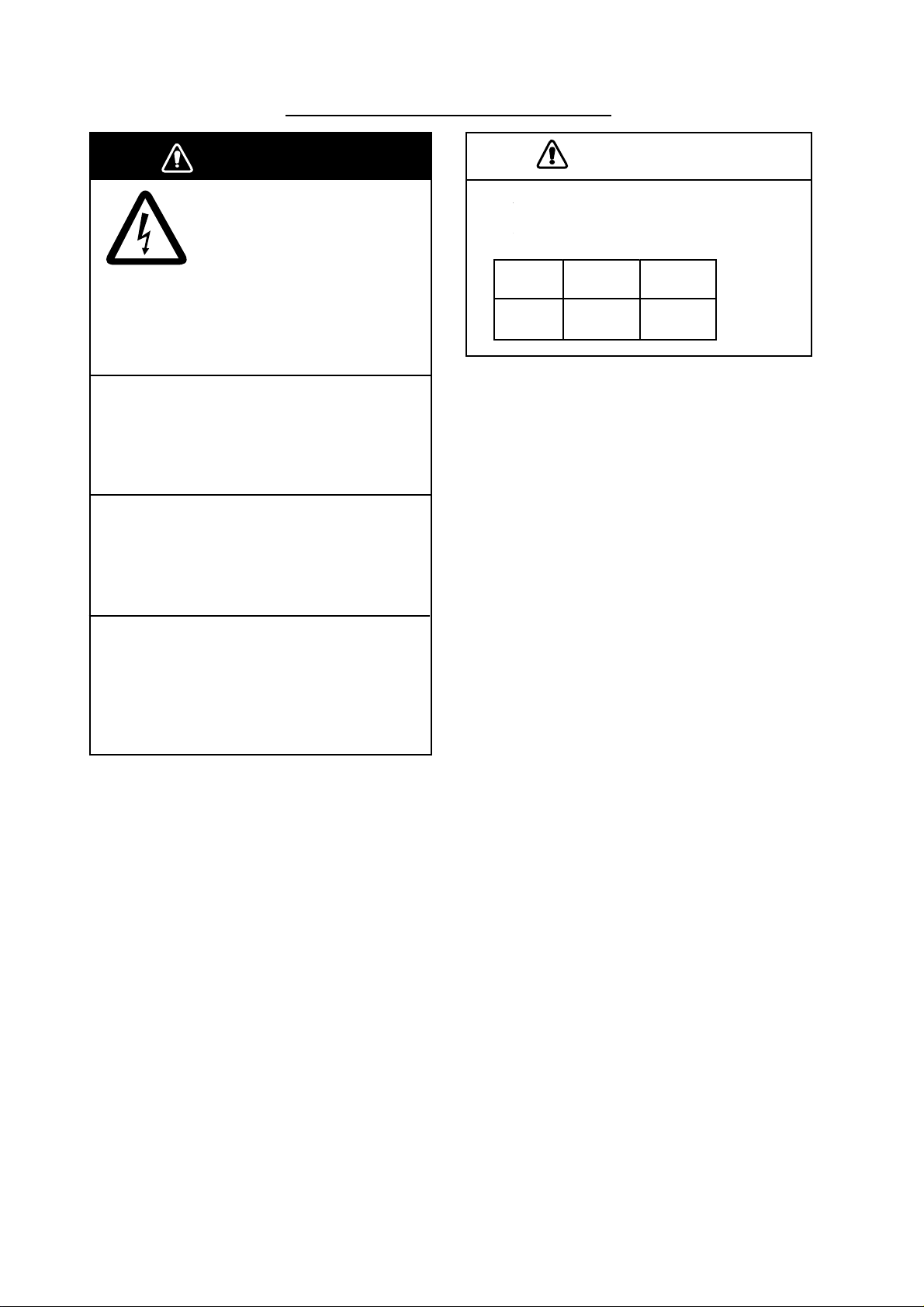
Observe the following compass safe
distances to prevent interference to a
magnetic compass:
Standard Steering
compass compass
Facsimile
Receiver
0.9 m 0.6 m
Be sure that the power supply is
compatible with the voltage rating of
the equipment.
Connection of an incorrect power supply
can cause fire or damage the equipment.
ii
offered by Busse-Yachtshop.com
Page 5

TABLE OF CONTENTS
FOREWORD ..................................................................................................................vi
SYSTEM CONFIGURATION ..........................................................................................ix
EQUIPMENT LISTS .......................................................................................................xi
OVERVIEW, SETUP ................................................................................................ 1-1
1.
1.1 Overview, Setup: NavNet.........................................................................................................1-1
1.1.1 Controls ......................................................................................................................... 1-1
1.1.2 Preparations for using the FAX-30 ................................................................................1-2
1.1.3 Accessing the FAX mode ..............................................................................................1-3
1.1.4 Choosing the receive mode........................................................................................... 1-4
1.1.5 Receive notification .......................................................................................................1-5
1.2 Overview, Setup: PC................................................................................................................ 1-6
1.2.1 Accessing the FAX-30 top display................................................................................. 1-6
1.2.2 Choosing the receive mode........................................................................................... 1-8
1.2.3 Logging out ....................................................................................................................1-8
2. FAX OPERATION: NAVNET.................................................................................... 2-1
2.1 Automatic Receiving ................................................................................................................ 2-1
2.1.1 Choosing channel .......................................................................................................... 2-1
2.1.2 Previewing image being received.................................................................................. 2-4
2.1.3 Stopping automatic receiving ........................................................................................ 2-4
2.2 Manually Starting, Stopping Receiving ....................................................................................2-5
2.2.1 Manually starting receiving ............................................................................................ 2-5
2.2.2 Manually stopping receiving .......................................................................................... 2-6
2.3 Timer Receiving .......................................................................................................................2-7
2.3.1 Setting timer receiving schedule ...................................................................................2-7
2.3.2 Turning on/off specific timer programs ........................................................................ 2-11
2.3.4 Clearing all timer programs ......................................................................................... 2-11
2.4 Displaying Facsimile Images ................................................................................................. 2-12
2.5 Processing Facsimile Images ................................................................................................ 2-13
2.5.1 Phase mismatch ..........................................................................................................2-13
2.5.2 Phasing signal out of synchronization ......................................................................... 2-14
2.5.3 Noise rejection............................................................................................................. 2-14
2.5.4 Image color .................................................................................................................. 2-15
2.5.5 Image format................................................................................................................2-15
2.5.6 Zooming images ..........................................................................................................2-16
2.5.7 Rotating images ........................................................................................................... 2-16
2.6 Erasing Facsimile Images...................................................................................................... 2-16
2.7 Preventing Erasure of Facsimile Images............................................................................... 2-17
2.8 Adding Facsimile Channels ...................................................................................................2-18
3. FAX OPERATION: PC............................................................................................. 3-1
3.1 Automatic Receiving ................................................................................................................ 3-1
3.1.1 Starting receiving ........................................................................................................... 3-1
3.1.2 Stopping receiving .........................................................................................................3-1
3.2 Timer Receiving .......................................................................................................................3-2
3.2.1 Setting, changing timer receiving schedule................................................................... 3-2
iii
offered by Busse-Yachtshop.com
Page 6

3.2.3 Turning on/off specific timer programs .......................................................................... 3-4
3.2.4 Clearing all timer programs ...........................................................................................3-4
3.3 Displaying Facsimile Images ................................................................................................... 3-5
3.4 Processing Facsimile Images .................................................................................................. 3-6
3.4.1 Phase mismatch ............................................................................................................ 3-6
3.4.2 Phasing signal out of synchronization ........................................................................... 3-7
3.4.3 Noise rejection............................................................................................................... 3-7
3.4.4 Image color .................................................................................................................... 3-8
3.4.5 Image format.................................................................................................................. 3-8
3.4.6 Rotating images............................................................................................................. 3-9
3.4.7 Zooming images ............................................................................................................ 3-9
3.4.8 Saving images ............................................................................................................... 3-9
3.5 Erasing Facsimile Images........................................................................................................3-9
3.6 Preventing Erasure of Facsimile Images............................................................................... 3-10
3.7 Adding Facsimile Channels ................................................................................................... 3-11
4. NAVTEX OPERATION: NAVNET............................................................................4-1
4.1 About Navtex Messages.......................................................................................................... 4-1
4.1.1 Message categories ......................................................................................................4-1
4.1.2 Receiving navtex messages.......................................................................................... 4-1
4.2 Setting Up Navtex Stations, Messages, Alarms...................................................................... 4-2
4.3 Previewing Incoming Navtex Messages.................................................................................. 4-5
4.4 Displaying Navtex Messages...................................................................................................4-6
4.4.1 Displaying navtex messages......................................................................................... 4-6
4.4.2 Remarks on navtex messages ...................................................................................... 4-7
4.5 Displaying the Navtex Station List ...........................................................................................4-8
4.6 Adding Navtex Stations............................................................................................................ 4-9
5. NAVTEX OPERATION: PC ......................................................................................5-1
5.1 About Navtex Messages.......................................................................................................... 5-1
5.1.1 Message categories ......................................................................................................5-1
5.1.2 Receiving navtex messages.......................................................................................... 5-1
5.2 Setting Up Navtex Stations, Messages ................................................................................... 5-2
5.3 Displaying Navtex Messages...................................................................................................5-3
5.4 Displaying the Navtex Station List ...........................................................................................5-4
5.5 Adding Navtex Stations............................................................................................................ 5-5
5.6 Editing Navtex Stations............................................................................................................ 5-6
5.7 Deleting Navtex Stations.......................................................................................................... 5-7
6. MAINTENANCE, TROUBLESHOOTING.................................................................6-1
6.1 Maintenance ............................................................................................................................6-1
6.2 Replacement of Fuse...............................................................................................................6-2
6.3 Troubleshooting ....................................................................................................................... 6-2
6.4 Diagnostics: NavNet ................................................................................................................6-3
6.5 Diagnostics: PC .......................................................................................................................6-4
6.6 Clearing Data: NavNet .............................................................................................................6-5
6.7 Clearing Data: PC .................................................................................................................... 6-6
6.8 All Clear (for technicians only)................................................................................................. 6-7
6.9 Simulation Mode ...................................................................................................................... 6-8
6.9.1 Accessing the simulation mode through NavNet ..........................................................6-8
6.9.2 Accessing the simulation mode through PC .................................................................6-9
iv
offered by Busse-Yachtshop.com
Page 7

7. INSTALLATION........................................................................................................ 7-1
7.1 Facsimile Receiver................................................................................................................... 7-1
7.2 Antenna Unit ............................................................................................................................7-2
7.2.1 General antenna connection ......................................................................................... 7-2
7.2.2 Wire antenna or whip antenna ......................................................................................7-2
7.2.3 Installation of preamp unit FAX-5 (option).....................................................................7-3
7.3 Wiring .......................................................................................................................................7-4
7.4 Supplying Power to the Preamp Unit....................................................................................... 7-6
7.5 Browser, PC Settings............................................................................................................... 7-7
7.5.1 Browser settings ............................................................................................................7-7
7.5.2 PC settings ....................................................................................................................7-8
APPENDIX ............................................................................................................... AP-1
Facsimile Stations........................................................................................................................ AP-1
Navtex Stations............................................................................................................................ AP-4
Menu Tree.................................................................................................................................... AP-9
SPECIFICATIONS.....................................................................................................SP-1
PACKING LIST
OUTLINE DRAWINGS
INTERCONNECTION DIAGRAM
SCHEMATIC DIAGRAM
INDEX.........................................................................................................................IN-1
v
offered by Busse-Yachtshop.com
Page 8

FOREWORD
A Word to the Owner of the FAX-30
FURUNO Electric Company thanks you for purchasing the FURUNO FAX-30 Facsimile
Receiver. We are confident you will discover why the FURUNO name has become
synonymous with quality and reliability.
For over 50 years FURUNO Electric Company has enjoyed an enviable reputation for
quality and reliability throughout the world. This dedication to excellence is furthered by our
extensive global network of agents and dealers.
Your equipment is designed and constructed to meet the rigorous demands of the marine
environment. However, no machine can perform its intended function unless properly
installed and maintained. Please carefully read and follow the operation, installation and
maintenance procedures set forth in this manual.
We would appreciate feedback from you, the end-user, about whether we are achieving our
purposes.
Thank you for considering and purchasing FURUNO.
Features
Connected to a 10.4-inch NavNet series display unit or a PC, the FAX-30 receives facsimile
images and navtex messages, transmitted from facsimile and navtex stations.
• Programmed with all existing facsimile stations and frequencies. User may program 320
channels.
• Fully automatic facsimile operation with built-in schedule timer. Storage for 30 timer
programs.
• Fully automatic selection of speed, IOC, phase alignment and frequency. Manual
selection also available.
• Connection to printer via a PC to print facsimile images and navtex messages.
• Facsimile images in monochrome, gray scale (8 tones) or color (three patterns).
• Built in navtex receiver. (The receiver does not conform to GMDSS regulations.)
vi
offered by Busse-Yachtshop.com
Page 9

Operational Characteristics
General
•
The equipment receives one facsimile image or naxtex message at a time. Thus, a
navtex message cannot be received when a facsimile image is being received and vice
versa, regardless of navtex message category.
•
Three receiving modes are available, facsimile, navtex, and facsimile(timer) & navtex.
When using the facsimile(timer) and navtex, the order of priority is
Facsimile(timer) (highest priority) → Navtex (lowest priority)
•
The FAX-30 does not have an internal clock, so time is input from the NavNet display or
the PC. (For PC-only configuration, time data is read when the browser accesses the
FAX-30. Therefore, turn on the FAX-30 before accessing it from the PC to allow for input
of time data, which is necessary for facsimile timer recording.) To receive time data, do
the following:
NavNet: Output the date and time data sentence ZDA through the NavNet network.
PC: Set the PC’s clock to the correct time.
•
If both a NavNet series unit and a PC are used, it is recommended to operate the FAX-30
from the PC because of the two different communication protocols. (Use the NavNet
series unit to feed navigation data to the PC.)
•
Navigation data must be fed through the network to use the automatic navtex mode.
Therefore, this mode is not available in the PC-only configuration.
NavNet
•
•
PC
•
•
The FAX-30 cannot be accessed from the NavNet for 15 seconds after the FAX-30 has
been turned on.
NavNet requirements:
Navionics: Ver. 15, Boot Ver. 2 (1950006002)
C-MAP: Ver. 11, Boot Ver. 2 (1950006002)
The FAX-30 cannot be accessed from the PC while the FAX-30 is loading data at start up.
Wait until the POWER LED flashing interval changes from 0.4 to two seconds before
accessing the FAX-30.
Most operating procedures in this manual are written for use with the Internet Explorer.
Menu items, control button names, etc. may be different on the Netscape Navigator.
•
PC requirements:
OS: Windows 98, 2000, XP
Memory: Min.128 MB
CPU: Min. 600 MHz
Resolution: 1024x768 pixels
vii
offered by Busse-Yachtshop.com
Page 10

•
Browser requirements:
Internet Explorer: Ver.5.01/5.5/6.0
Netscape Navigator: Ver.4.78/6.2/7.0
•
OS and browser compatibility
Internet Explorer Netscape Navigator
Ver. 5.01 Ver. 5.5 Ver 6.0 Ver. 4.78 Ver. 6.2 Ver. 7.0
Windows 98 OK OK # *1, *2 *2 NO, *3
Windows 2000 OK OK OK *1 # OK
Windows XP # # OK # # OK
*1 A facsimile image may not be updated after it has been processed (noise limiter,
zoom, etc.). To update the image, click the right button on the mouse while holding
down the [SHIFT] key and then choose Reload.
*2 Connection is occasionally interrupted. In case of 4.78 + Win 98, the message “A
network error occurred: unable to connect to server (TCP Error: Not enough
memory). The server may be down or unreachable. Try connecting again later.” is
displayed. To restore the connection, press [Ctrl]+[Alt]+[Delete] to force quit Netscape.
Then, reopen Netscape and try to connect again.
*3 Connection is frequently interrupted and cannot be restored.
# Not verified.
•
Use of older OS with recent browser will result in extremely slow operation.
•
If the browser goes into timeout while an image is being received, access to the FAX-30
may be interrupted. In this case, click the right button on the mouse and click Refresh.
•
Most PC operations are done with the left button on the mouse. The exception is saving a
facsimile image which is done with the right button.
•
The FAX-30 cannot be simultaneously accessed by multiple PCs. For this reason, be
sure to use the logout feature to logout a PC from the FAX-30 when its use is not
required.
•
If the FAX-30 appears to be abnormal, the browser version may not be compatible or
browser settings may be wrong. See the browser requirements on the previous page, the
browser and OS compatibility table above and the browser settings in paragraph 7.5.1.
•
The FAX-30’s HTTP and HTML versions are as below.
HTTP: Ver. 1.0
HTML: Ver. 4.01
viii
offered by Busse-Yachtshop.com
Page 11
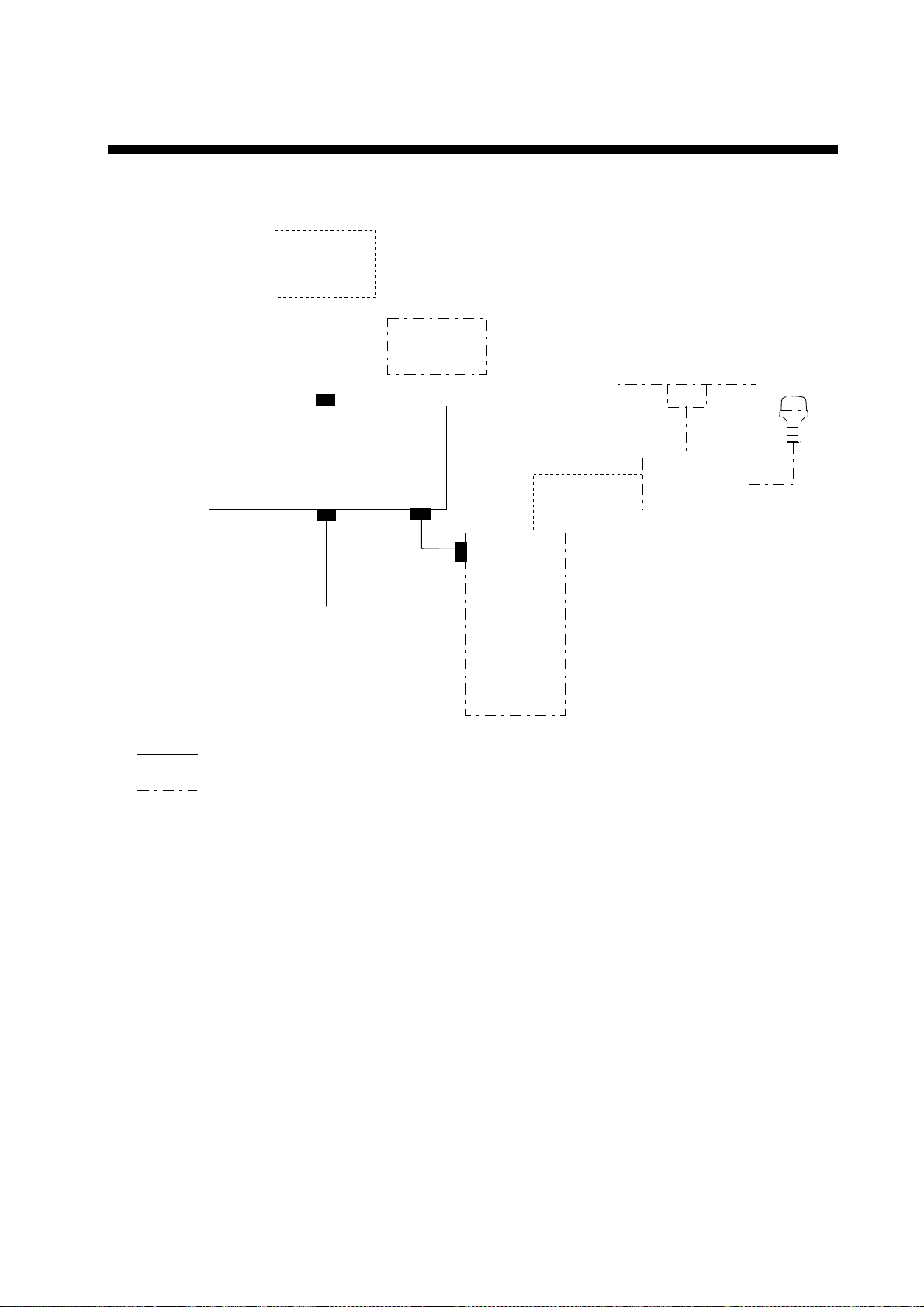
SYSTEM CONFIGURATION
Network installation
PREAMP
FAX-5
Wire
Antenna
FACSCIMILE RECEIVER
FAX-30
Radar,
Plotter
Ship’s Mains
12-24 VDC
: Standard
: Option
: User Supply
10.4" NavNet Series
HUB*
* = HUB is not required to connect
NavNet display unit directly.
Network installation
ix
offered by Busse-Yachtshop.com
Page 12
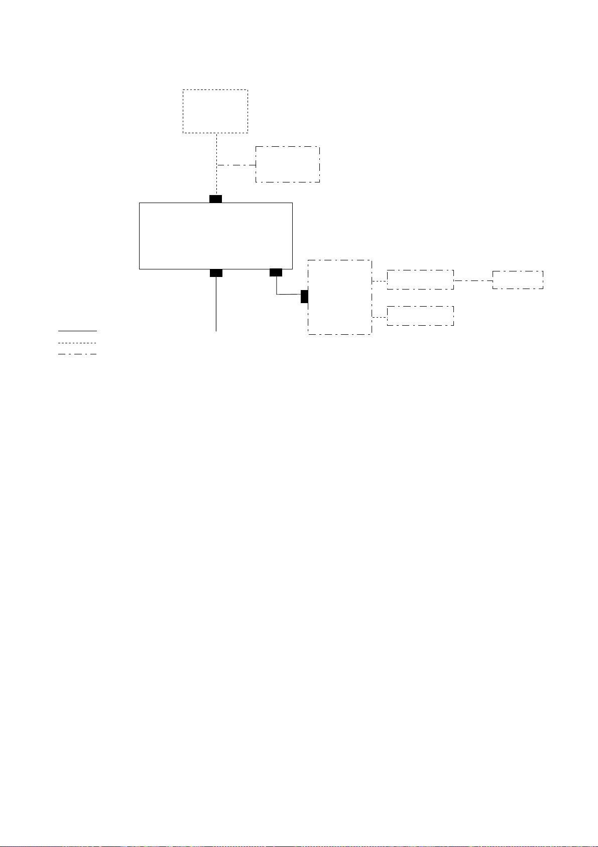
PC installation
PREAMP
FAX-5
Wire
Antenna
FACSIMILE
RECEIVER
FAX-30
: Standard
: Option
: Local Supply
* = HUB is not required to connect single PC.
Ship’s Mains
12-24 VDC
HUB*
PC
PC
FAX-30 cannot be
accessed by more
than one PC at a time.
Printer
x
offered by Busse-Yachtshop.com
Page 13

EQUIPMENT LISTS
Standard supply
Name Type Code No. Qty Remarks
Facsimile
Receiver
Spare Parts SP08-01901 005-952-780 1 set Fuse, 2 pcs.
Installation
Materials
FAX-30-E-AN — With Net cable
FAX-30-E-AP — With PC cable
FAX-30-E-N —
CP08-01700 000-057-103 • Power Cable
CP08-01710 000-057-104 • Power Cable
CP08-01720 000-057-105
Select
one
Choose
one
No connection cable
MJ-A3SPF0024-035
• Net Cable
MJ-A6SPF0014-050
• Tapping screw (5 X 20)
MJ-A3SPF0024-035
• PC Cable
MJ-A6SPF/TM11AP8C050
• Tapping screw (5X20)
• Power Cable
MJ-A3SPF0024-035
• Tapping screw (5X20)
xi
offered by Busse-Yachtshop.com
Page 14

Optional supply
Name Type Code No. Remarks
Preamp Unit FAX-5 000-075-016 w/15 m cable
Hose Clamp OP08-11 005-946-960 For fixing FAX-5 to a mast
Whip Antenna 04S4176 000-112-845 2.6 m, for FAX-5
Extension Cable
Kit
Cable Assy. MJA6SRMD/TM11AP8-005 000-144-463 Net conversion cable, for HUB,
Cable Assy. MJ-A6SPF/TM11AP8C050 000-146-289 Net conversion cable, for HUB,
Coaxial Plug FM-MP-7 000-108-859 For cable 7C2V, RG8/U, etc.
Adaptor MP-M3A 000-108-860 For cable 3C2V, 3D2V, etc.
Adaptor MP-M5A 000-108-861 For cable 5C2V, 5D2V, etc.
Cable Assy. MJ
OP-04-2 *10* 000-041-174
OP-04-2 *20* 000-041-175
OP-04-2 *30* 000-041-176
OP-04-2 *40* 000-041-177
OP-04-2 *50* 000-041-178
MJ-A6SPF0014-010 000-144-421 1 m
MJ-A6SPF0014-050 000-144-422 5 m
MJ-A6SPF0014-100 000-144-423 10 m
MJ-A6SPF0014-200 000-144-424 20 m
MJ-A6SPF0014-300 000-144-425 30 m
M-connector at both ends
NavNet
PC
Net cable
xii
offered by Busse-Yachtshop.com
Page 15
1. OVERVIEW, SETUP
1.1 Overview, Setup: NavNet
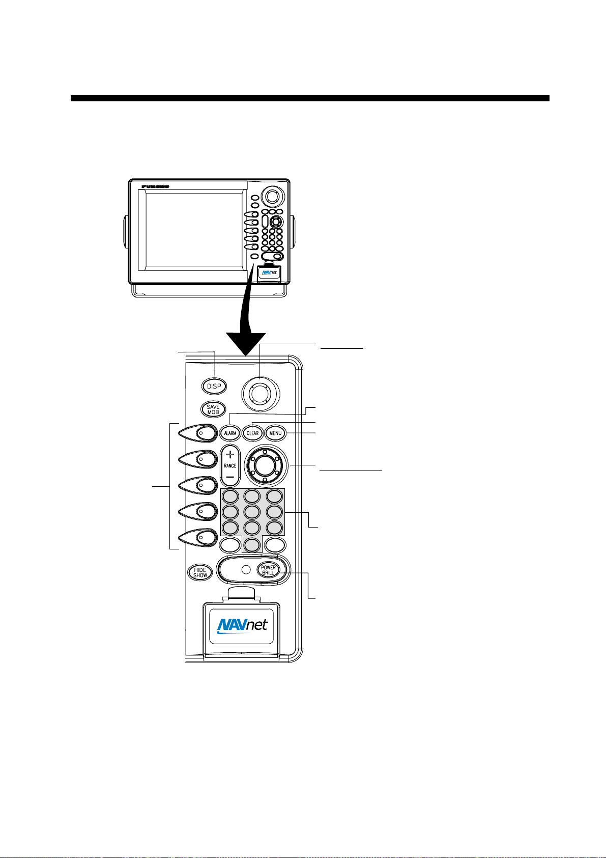
1.1.1 Controls
Displays the mode
selection window.
Soft keys
ABC
JKL
STU
EBL
VRM
Trackball
Chooses menu items and options.
Displays alarm message board.
Clears data.
Opens FAX-30 menu; returns to standby.
ENTER knob
Push: Registers setting.
DEF
MNO
VWX
_'#
GHI
2
3
PQR
5
6
YZ&
8
9
GAIN
0
1
4
7
Rotate: Selects menu items and options.
May also be used to enter alphanumeric data.
Enter alphanumeric data.
Long press: Turns power off.
Momentary press: Turns the power on;
opens the display for adjustment of brilliance.
Controls
Note 1: For NavNet operating procedures, see the operator’s manual of the
NavNet display unit.
Note 2: The example screens shown in this manual may not match the screens
you see. The screen you see depends on your equipment settings and
system configuration.
1-1
offered by Busse-Yachtshop.com
Page 16
1. OVERVIEW, SETUP
1.1.2 Preparations for using the FAX-30
The NavNet series display unit must output the date and time data sentence
ZDA through the network in order to use the facsimile timer recording feature.
Further, automatic navtex requires the geographical position data sentence GGA
(GPS position fix data) or GLL (geographic position, latitude/longitude). Output
appropriate data sentences from the NavNet display unit to the FAX-30 as
follows:
1. Turn on the NavNet display unit. From the radar, plotter or echo sounder
display, press the [MENU] key.
2. Press the SYSTEM CONFIGURATION soft key.
3. Press the SYSTEM SETUP soft key.
4. Press the PORT SETUP soft key.
5. Press the OUTPUT THROUGH NETWORK soft key.
AAM
APB
BOD
BWR*
DPT
GGA
GLL
GTD
MTW
RMA
RMB
RMC
VHW
VTG
WPL
XTE
ZDA
HDT
HDG
MWV
TTM
--
ON
--
--
--
--
ON
--
--
-ON
ON
-ON
--
-ON
--
--
--
--
SELECT
SNTNC
ON/OFF
RETURN
*: BWR: Rhumb line
BWC: Great circle
Select sentence window
6. Rotate the [ENTER] knob to choose GGA, GLL or ZDA.
7. Press the ON/OFF soft key to display ON.
8. Repeat steps 6 and 7 to set the other two sentences to ON.
9. Press the [MENU] key to close the menu.
1-2
offered by Busse-Yachtshop.com
Page 17
1.1.3 Accessing the FAX mode
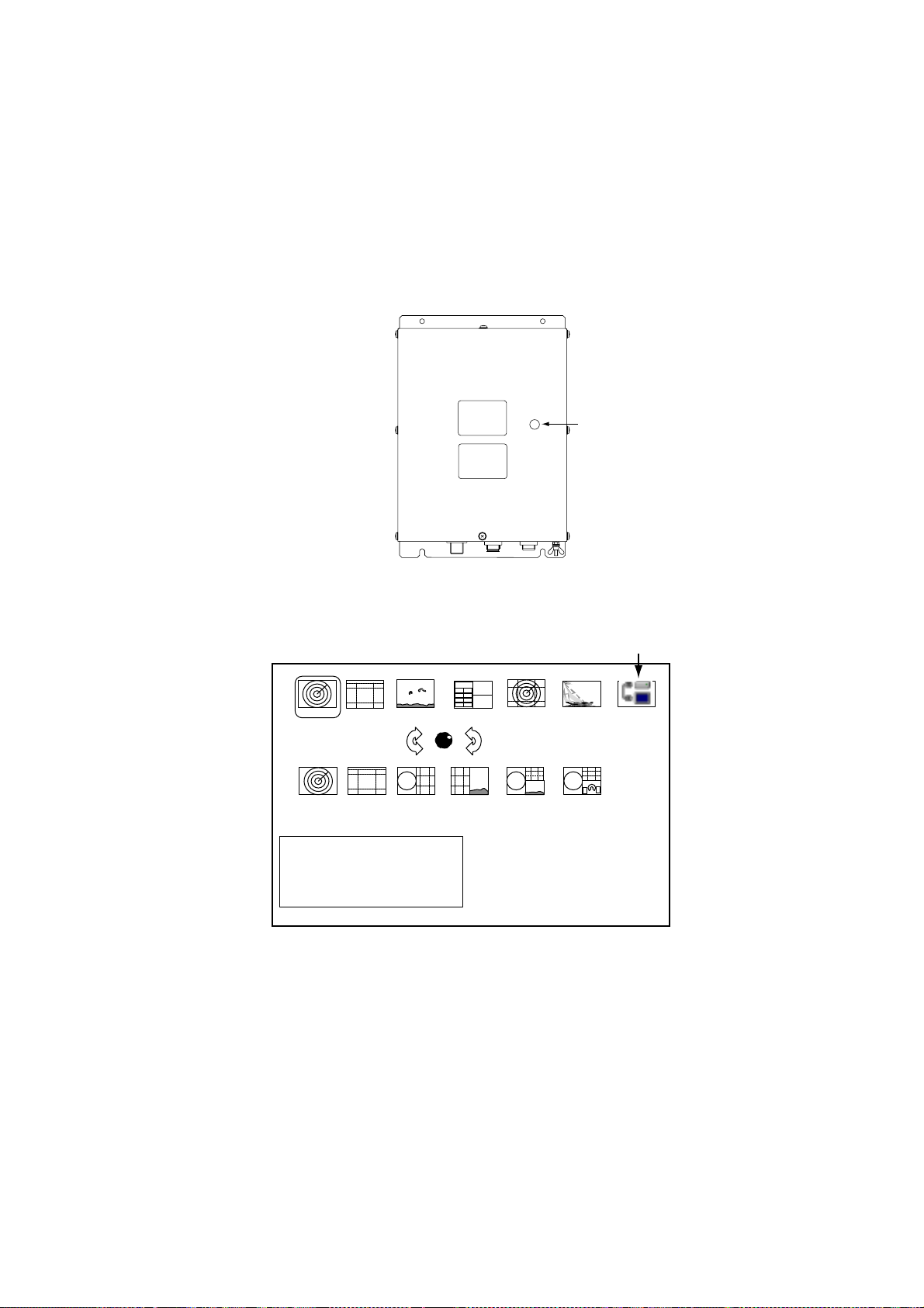
1. Turn on the FAX-30 at the ship’s mains switchboard. The FAX-30 proceeds in
the following sequence:
a) The FAX-30 starts initial set up, which takes about 15 seconds.
b) The FAX-30 transfers (loads) data from the ROM to the RAM. At this time the
LED flashes every 0.4 seconds.
c) After all data has been loaded, which takes about two minutes, the LED
flashes every two seconds, indicating the FAX-30 is ready for operation.
1. OVERVIEW, SETUP
LED
(green)
FAX-30, top view
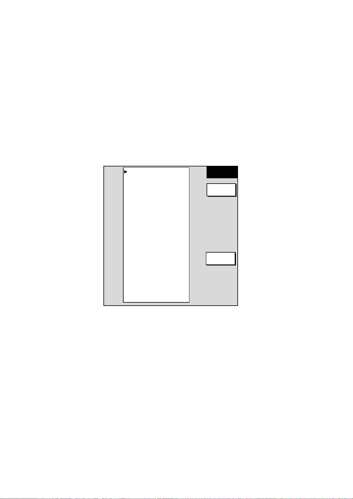
2. Press the [DISP] key to show the display selection window.
Fax mode icon
RADAR
HOTPAGE 1 HOTPAGE 2
· TURN KNOB TO SELECT MODE
AND PUSH KNOB TO ENTER.
· PUSH ANY SOFTKEY TO
SELECT IMAGE SOURCE.
PLOTTER
SOUNDER
HOTPAGE 3
NAV DATA
HOTPAGE 4
OVERLAY
HOTPAGE 5
EXT VIDEO
HOTPAGE 6
WXFAX
Display selection window
3. Rotate the [ENTER] knob to choose the WXFAX icon.
4. Push the [ENTER] knob to show the fax standby display.
Note 1: The FAX-30 cannot be accessed during the 15-second start up period
which occurs after the power has been turned on.
Note 2: If the FAX-30 is not connected to the NavNet display unit when the
display unit is powered, the message “AUX SOURCE IS
DISCONNECTED. PUSH ENT KNOB TO EXIT.” appears. Check
connections between the FAX-30 and the NavNet display unit.
Note 3: “LOAD IMAGES” is displayed while the FAX-30 is loading data.
1-3
offered by Busse-Yachtshop.com
Page 18
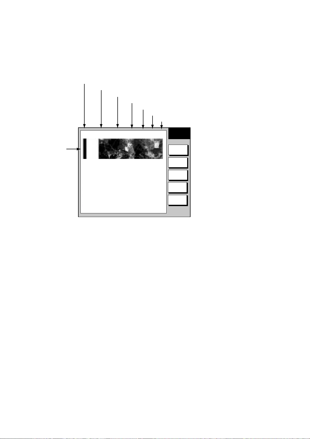
1. OVERVIEW, SETUP
The standby display is where you begin all facsimile and navtex operations. If a
facsimile image has been received, the latest facsimile image is displayed.
Facsimile image area
Standby display
1.1.4 Choosing the receive mode
The FAX-30 has three modes: facsimile only, navtex only, and facsimile (timer) &
navtex. Choose desired mode as follows:
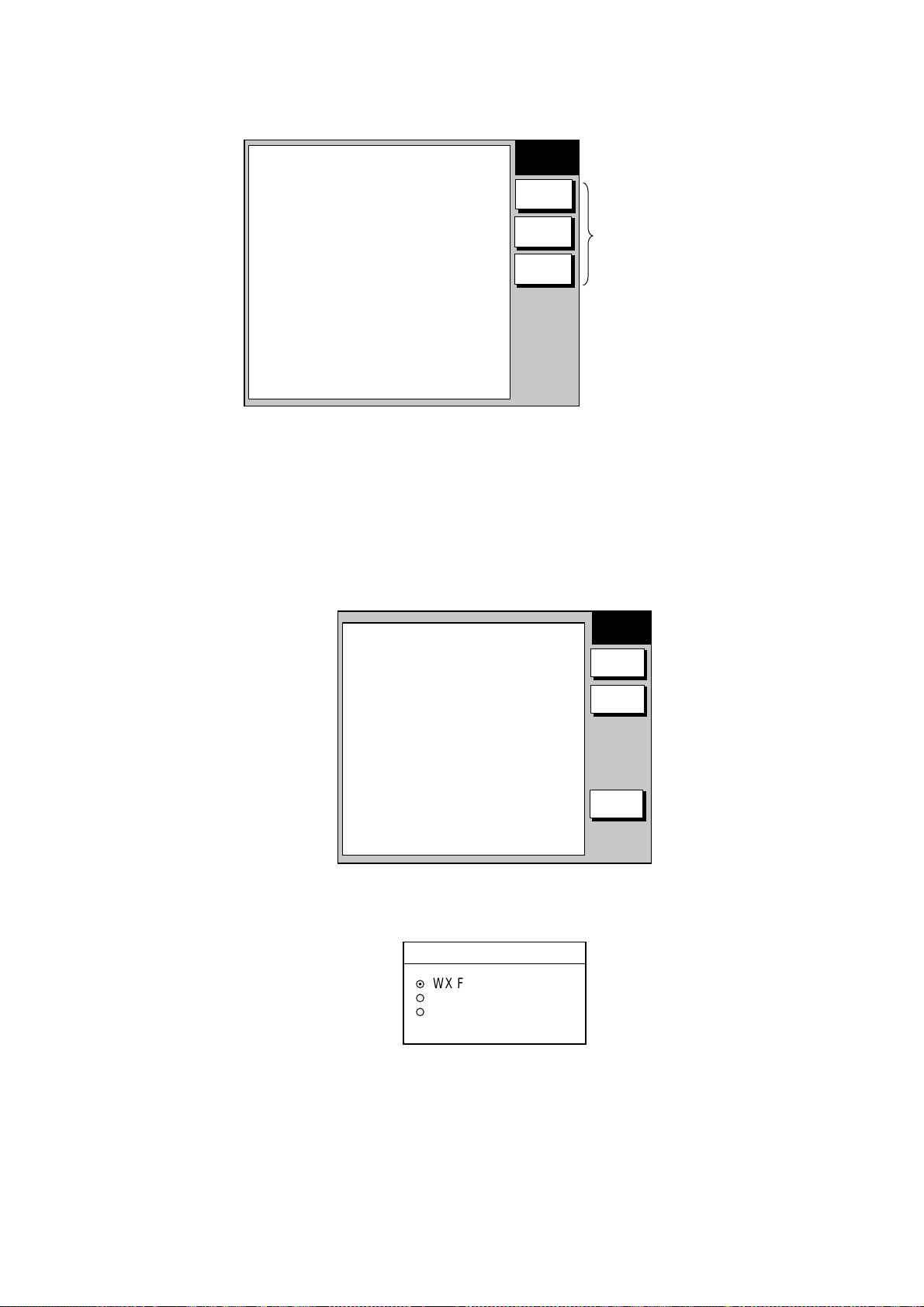
1. At the facsimile standby display, press the MODE SETUP soft key.
FAX-30
WX FAX
NAVTEX
MODE
SETUP
Soft keys
(Facsimile image area)
Receive mode setup screen
2. Press the RX MODE soft key.
RX MODE
▲
¤
WX FAX
¡
NAVTEX
¡
FAX (TIMER) & NAV
▼
RX mode options
MODE
SETUP
RX
MODE
RX
NOTICE
RETURN
3. Rotate the [ENTER] knob to choose receive mode desired and press the
ENTER soft key.
1-4
offered by Busse-Yachtshop.com
Page 19

1.1.5 Receive notification
1. OVERVIEW, SETUP
You may wish to be notified after a facsimile image or navtex message arrives.
A
U
Notification is done by showing the “fax/navtex received” icon (
) at the
X
left-hand side of the screen in display modes other than the fax mode.
1. At the facsimile standby display, press the MODE SETUP soft key.
2. Press the RX NOTICE soft key.
RX NOTICE
▲
¤
ON
¡
OFF
▼
RX notice options
3. Rotate the [ENTER] knob to choose ON or OFF as appropriate.
4. Press the ENTER soft key.
1-5
offered by Busse-Yachtshop.com
Page 20

1. OVERVIEW, SETUP
1.2 Overview, Setup: PC
1.2.1 Accessing the FAX-30 top display
1. Turn on the FAX-30 at the mains switchboard. The FAX-30 proceeds in the
following sequence:
a) The FAX-30 starts initial set up, which takes about 15 seconds.
b) The FAX-30 transfers (loads) data from the ROM to the RAM. At this time the
LED flashes every 0.4 seconds.
c) After all data has been loaded, which takes about two minutes, the LED
flashes every two seconds, indicating the FAX-30 is ready for operation.
2. Start up the browser software.
3. After the LED on the FAX-30 starts flashing every two seconds, type in the
FAX-30’s URL http://172.31.8.1 and then press the [Enter] key. The facsimile
receiver top display appears. (For one-touch access to the FAX-30 make a
bookmark.)
FACSIMILE RECEIVER
FAX-30
WX FAX
NAVTEX
LOGOUT
Facsimile receiver top display
4. Click WX FAX for facsimile or NAVTEX for navtex to show the corresponding
standby display, which is where you begin all facsimile (or navtex) operations.
1-6
offered by Busse-Yachtshop.com
Page 21
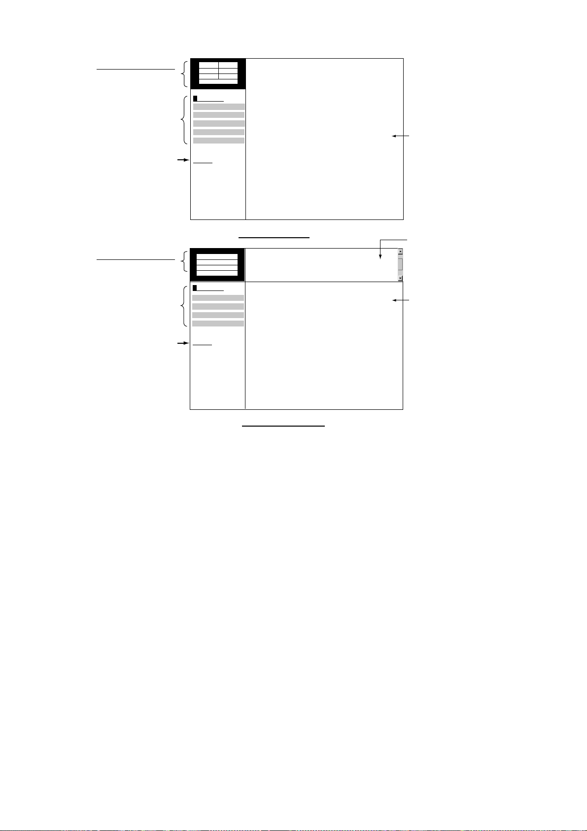
1. OVERVIEW, SETUP
Facsimile image data
(Changes with picture
received.)
Top menu
Click to return
to top display
Navtex message data
(Changes with message
received.)
Top menu
Click to return
to top display
100N 3625.kHz
IOCXX10 XXXrpm
SS=XXX SN=XX
STBY
MENU
CHANNEL SETUP
TIMER SETUP
EDIT STATION LIST
SYSTEM SETUP
RX MODE
<< Top
518kHz
AUTO LAT/LON OK
SS=10
STBY
MENU
RX SETUP
EDIT STATION LIST
SYSTEM SETUP
RX MODE
<< Top
Received facsimile image
thumbnails appear here.
Fax standby display
Navtex message list
appears here.
Navtex message
display area
Navtex standby display
Standby displays
After you are in a standby display time data is transferred from the PC to the
FAX-30.
Note 1: After turning on the FAX-30 be sure to access it from the PC. Then,
even if the PC is turned off, time data is stored in the FAX-30, for use
with timer recording.
Note 2: The example screens shown in this manual may not match the screens
you see. The screen you see depends on your equipment settings and
system configuration.
1-7
offered by Busse-Yachtshop.com
Page 22

1. OVERVIEW, SETUP
1.2.2 Choosing the receive mode
The FAX-30 has three modes: facsimile only, navtex only, and facsimile (timer) &
navtex. Choose desired mode as follows.
1. At the facsimile or navtex standby display, click RX MODE.
RX MODE
¤
WX FAX
¡
NAVTEX
¡
FAX(TIMER) & NAVTEX
OK
< back
RX mode options
2. Click receive mode desired and then click OK.
3. Click “<back” or Back button to return to the top menu.
1.2.3 Logging out
The FAX-30 cannot be accessed simultaneously by multiple PCs. For this
reason, log out a PC from the FAX-30 when its use is not required.
1. At the facsimile or navtex menu display, click “<Top” to return to the facsimile
receiver top display. (See the illustration at the top of the previous page.)
2. Click LOGOUT to logout the PC from FAX-30.
1-8
offered by Busse-Yachtshop.com
Page 23
2. FAX OPERATION: NAVNET
2.1 Automatic Receiving
Once you choose the facsimile station from which to receive, the system goes
into standby to await the start signal from the facsimile station.
2.1.1 Choosing channel
1. At the standby display, press the WX FAX soft key. Thumbnails of received
images are shown.
THUMBNAILS OF RECEIVED IMAGES
JMH JUN/04 02:46 JMH JUN/05 01:29 JMH JUN/05 01:32
JMH JUN/05 03:46 JMH JUN/05 04:29 JMH JUN/05 05:21
Thumbnails of received images
2. Press the RCV WX FAX soft key.
100N JMH 7305.0KHZ IOC288 180rpmSS=57 SN=31
THUMBNAILS
SELECT
IMAGE
RCV
WX FAX
RETURN
RECEIVE
WX FAX
CH
SETUP
TIMER
SETUP
START
RX
STOP
RX
RETURN
RECEIVE WX FAX display
2-1
offered by Busse-Yachtshop.com
Page 24
2. FAX OPERATION: NAVNET
3. Press the CH SETUP soft key.
Image data
Changes when facsimile
picture is received.
See paragraph 2.1.2.
100N JMH 3622.5kHz IOCXXX XXrpm SS=00 SN=00 RCV
Fax channel setup window
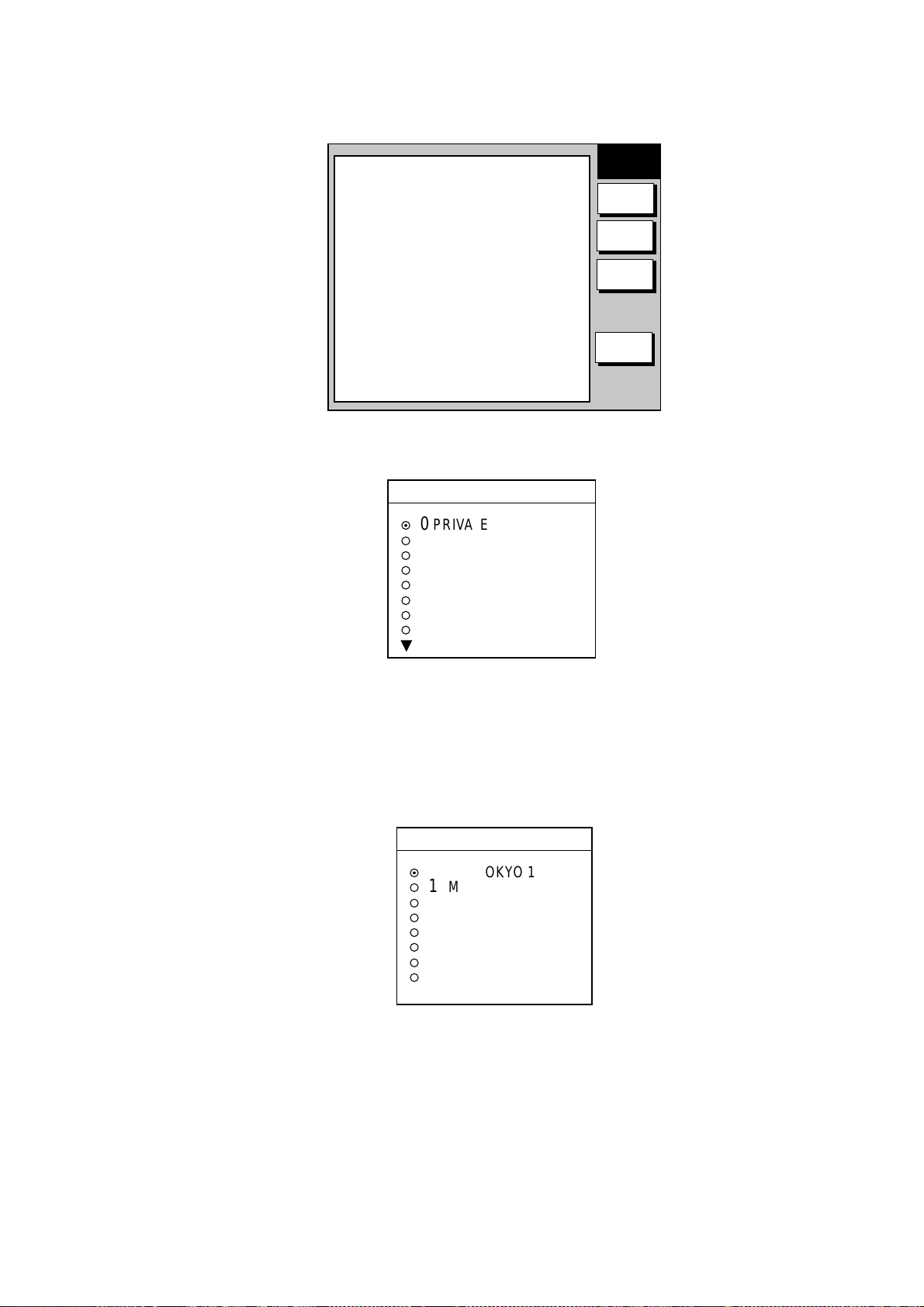
4. Press the ZONE soft key to display the ZONE options.
ZONE
▲
¤
0
PRIVATE
1
NORTHWEST PACIFIC
¡
¡
2
NORTHEAST PACIFIC
¡
3
SOUTH PACIFIC/INDIAN
¡
4
SOUTH ATLANTIC
¡
5
NORTHWEST ATLANTIC
¡
6
NORTHEAST ATLANTIC
¡
7
NORTH ATLANTIC
▼
CHANNEL
SETUP
ZONE
STA
CH
FREQ
RETURN
Zone options
5. Rotate the [ENTER] knob to choose zone desired and push the ENTER soft
key. (Zone 0 and 9 are for user-set zones.)
6. Press the STATION soft key to show the STATION options. If the ZONE
chosen at step 5 is “1 NORTHWEST PACIFIC,” for example, the STATION
options are as below.
STATION
▲
¤
0
JMH /TOKYO 1
1
JMJ /TOKYO 2
¡
¡
2
JJC /KYODO 9MG
¡
3
JFA /CHUO GYOGYOU
¡
4
3SD /BEIJING
¡
5
BAF /BEIJING
¡
6
BDF /SHANGHAI
¡
7
BMF /TAIPEI
▼
Station options (Example: stations of northwest pacific)
7. Rotate the [ENTER] knob to choose desired station and press the ENTER
soft key.
2-2
offered by Busse-Yachtshop.com
Page 25
2. FAX OPERATION: NAVNET
8. Press the CHANNEL soft key to show the CHANNEL options. If you have
chosen “0 JMH/TOKYO 1” at step 7, for example, the CHANNEL options are
as below.
CHANNEL
▲
AUTO
¤
0 03622.5 kHz
¡
¡
1 04902.0 kHz
¡
2 07305.0 kHz
¡
3 09970.0 kHz
¡
4 13597.0 kHz
¡
5 18220.0 kHz
¡
6 23522.9 kHz
▼
Channel options (Example: JMH/Tokyo)
9. Rotate the [ENTER] knob to choose channel desired and press the ENTER
soft key.
10. If necessary you may fine tune the frequency. Press the FREQ soft key.
FREQUENCY
03622.5 kHz
Frequency entry window
11. Use the alphanumeric keys or the [ENTER] knob to enter appropriate
frequency and press the ENTER soft key. (You may choose the location
where to enter data by operating the trackball.)
12. Press the RETURN soft key several times to return to the standby display.
Then, the FAX-30 will receive the next scheduled broadcast from the station
selected. When the FAX-30 receives the start signal from the facsimile station it
automatically adjusts itself to match speed, IOC (Index of Cooperation) and
phase of the station’s transmitter. Facsimile images are received line by line,
taking 30-40 minutes to receive depending on the size of the image and rotation
speed of the drum at the facsimile transmitter. After a facsimile image is received
it is compressed and stored in image memory and then posted on the
“Thumbnails of received images” screen (see paragraph 2.4). This process takes
from three to five minutes. You can see the image being received by pressing
the WX FAX soft key on the fax standby display and then hitting the RCV WX
FAX soft key.
2-3
offered by Busse-Yachtshop.com
Page 26
2. FAX OPERATION: NAVNET
2.1.2 Previewing image being received
To preview an image while it is being received, do the following:
1. At the fax standby display, press the WX FAX soft key.
2. Press the RCV WX FAX soft key.
Zone/Station/Channel
Frequency
IOC (288 or 576)
Speed (60, 90, 120, 180, 240)
Signal Strength (Range: 0-99, Typical: 30-70)
Signal-to-Noise Ratio (Range: 0-99, Typical: 20-60)
100N JMH 3622.5kHz IOC288 180rpm SS=57 SN=31 RCV
Receiving facsimile image
RECEIVE
WX FAX
Image being
received
Facsimile receiving display
2.1.3 Stopping automatic receiving
You can stop automatic receiving at any time by doing the following:
1. At the standby display, press the WX FAX soft key.
2. Press the RCV WX FAX soft key.
3. Press the STOP RX soft key. The indication “RCV” is replaced with “STBY.”
4. Press the RETURN soft key.
CH
SETUP
TIMER
SETUP
START
RX
STOP
RX
RETURN
2-4
offered by Busse-Yachtshop.com
Page 27
2. FAX OPERATION: NAVNET
2.2 Manually Starting, Stopping Receiving
2.2.1 Manually starting receiving
This section shows you to manually receive a facsimile broadcast. For example,
you may want to receive a facsimile broadcast already in progress or receive
from a facsimile station that does not use start and stop signals. Further, you
may wish to stop reception to receive an image from a different station.
To manually receive a facsimile, you will first need to set a channel, referring to
paragraph 2.1. Then, do the following:
1. At the standby display, press the WX FAX soft key.
2. Press the RCV WX FAX soft key.
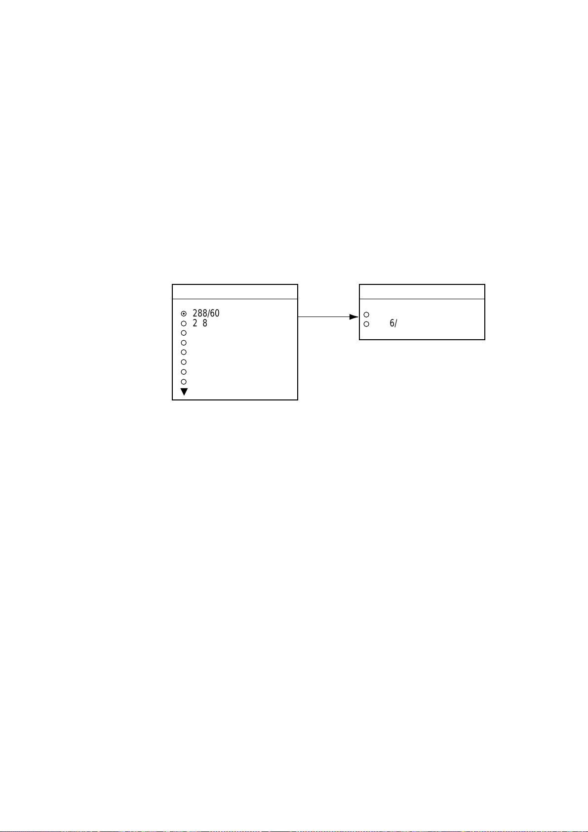
3. Press the START RX soft key.
The options shown are IOC (Index of Cooperation)/speed.
START RX
▲
¤
288/60
288/90
¡
¡
288/120
¡
288/180
¡
288/240
¡
576/90
¡
576/90
¡
576/120
▼
Rotate
[ENTER]
knob to
scroll.
Start RX options
START RX
▲
576/180
¡
576/240
¡
4. Rotate the [ENTER] knob to choose the correct combination of IOC and
speed of the facsimile transmitting station. IOC is the line density standard
assigned by WMO: IOC 576, high density, IOC 288, low density. Speed is the
rotation speed of the drum (on which the original image is fitted) at the
facsimile transmitter: 60, 90 ,120, 180 or 240 rpm.
5. Press the ENTER soft key.
6. Press the RETURN soft key.
Then, the FAX-30 will receive the current broadcast from the station selected.
Facsimile images are received line by line, taking 30-40 minutes to receive
depending on the size of the image and drum rotation speed at the facsimile
station. After a facsimile image is received it is compressed and stored in the
image memory and then posted on the “Thumbnails of received images” screen
(see paragraph 2.4). This process takes 3-5 minutes. You can see the image
being received by pressing the WX FAX soft key on the fax standby display and
then hitting the RCV WX FAX soft key.
2-5
offered by Busse-Yachtshop.com
Page 28
2. FAX OPERATION: NAVNET
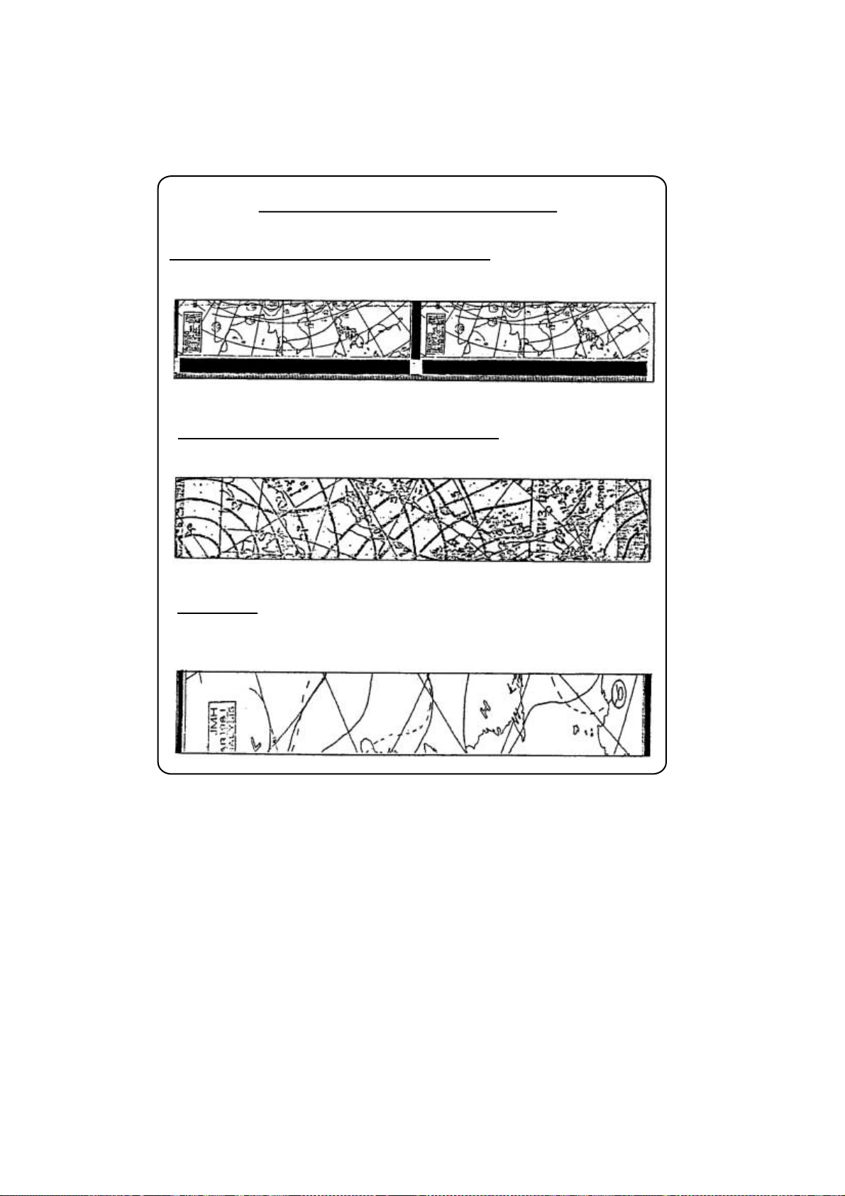
Be sure to choose the correct speed and IOC, otherwise the image will be
received as shown in the illustration below. You may change the IOC and speed
while the image is being received.
Wrong Speed or IOC and Image
Wrong speed: "60" chosen instead of "120"
Two images are displayed.
Wrong speed: "120" chosen instead of "60"
Overlapped image appears.
Wrong IOC
The image will be extended ( or foreshortened) when "288" (or 576)
is selected for transmission with the IOC of "576 (or 288)."
Wrong speed or IOC and image
2.2.2 Manually stopping receiving
1. At the standby display, press the WX FAX soft key.
2. Press the RCV WX FAX soft key.
3. Press the STOP RX soft key.
4. Press the RETURN soft key.
2-6
offered by Busse-Yachtshop.com
Page 29
2.3 Timer Receiving
Most facsimile stations transmit facsimiles in accordance with a schedule issued
by relative meteorological observatory. (You can find facsimile schedules in the
publication “Meteorological Facsimile Broadcasts,” available through
meteorological observatory bodies.) If you wish to receive a certain facsimile
broadcast on a daily basis, therefore, the timer receiving mode will virtually allow
you “hands-off” automatic operation. 30 timer programs may be set.
2.3.1 Setting timer receiving schedule
Note that the data sentence ZDA must be output through the network for the
timer to function.
1. At the standby display, press the WX FAX soft key.
2. Press the RCV WX FAX soft key.
3. Press the TIMER SETUP soft key.
2. FAX OPERATION: NAVNET
Timer schedule,
in time order
from closest
to furthest.
No. 05 10:30-14:05 100N JMH 3662.5 kHz
No. 06 14:30-16:40 100N JMH 3662.5 kHz
No. 07 16:40-19:00 100N JMH 3662.5 kHz
No. 01 19:05-19:15 100N JMH 3662.5 kHz
Only the latest
10 programs
are displayed.
Timer setup screen
4. Press the PROG LIST soft key.
Start, end time
▲
No.01 12:30-14:00 100N JMH ON
No.02 NOT PROGRAMMED
No.03 NOT PROGRAMMED
No.04 NOT PROGRAMMED
No.05 NOT PROGRAMMED
No.06 NOT PROGRAMMED
No.07 NOT PROGRAMMED
No.08 NOT PROGRAMMED
No.09 NOT PROGRAMMED
No.10 NOT PROGRAMMED
NEXT PAGE
Zone/Station/Channel
Facsimile station
Timer ON
PROGRAM
LIST
EDIT
ON/OFF
CLEAR
ALL
RETURN
TIMER
SETUP
START
TIMER
PROG
LIST
RETURN
Timer schedule list
2-7
offered by Busse-Yachtshop.com
Page 30
2. FAX OPERATION: NAVNET
5. Rotate the [ENTER] knob to choose program number desired and then press
the EDIT soft key.
▲
ZONE 1 NORTHWEST PACIFIC
STATION 0 JMH/TOKYO No.1
CHANNEL 0 3622.5 kHz
IOC AUTO
SPEED AUTO
START TIME 00:00
END TIME 00:00
FREQUENCY 00000.0 kHz
Timer schedule menu
6. ZONE is selected; press the EDIT soft key.
ZONE
▲
¤
0
PRIVATE
1
NORTHWEST PACIFIC
¡
¡
2
NORTHEAST PACIFIC
¡
3
SOUTH PACIFIC/INDIAN
¡
4
SOUTH ATLANTIC
¡
5
NORTHWEST ATLANTIC
¡
6
NORTHEAST ATLANTIC
¡
7
NORTH ATLANTIC
▼
EDIT
PROGRAM
EDIT
SAVE
CLEAR
CANCEL
Zone options
7. Rotate the [ENTER] knob to choose zone desired and press the ENTER soft
key.
8. Rotate the [ENTER] knob to choose STATION and press the EDIT soft key. If
you have chosen “1 NORTHWEST PACIFIC” at step 7, for example, the
STATION options are as below.
STATION
▲
¤
0
JMH /TOKYO 1
1
JMJ /TOKYO 2
¡
¡
2
JJC /KYODO 9MG
¡
3
JFA /CHUO GYOGYOU
¡
4
3SD /BEIJING
¡
5
BAF /BEIJING
¡
6
BDF /SHANGHAI
¡
7
BMF /TAIPEI
▼
Station options (Example: N Pacific W Part)
9. Rotate the [ENTER] knob to choose desired station and press the ENTER
soft key.
2-8
offered by Busse-Yachtshop.com
Page 31

2. FAX OPERATION: NAVNET
10. Rotate the [ENTER] knob to choose CHANNEL and press the EDIT soft key.
If you have chosen “0 JMH/TOKYO 1” at step 9, for example, the CHANNEL
display looks as below.
CHANNEL
▲
AUTO
¤
0
03622.5 kHz
¡
¡
1
04902.0 kHz
¡
2
07305.0 kHz
¡
3
09970.0 kHz
¡
4
13597.0 kHz
¡
5
18220.0 kHz
¡
6
23522.9 kHz
▼
Channel options (Example: station JMH)
11. Rotate the [ENTER] knob to choose channel desired and press the ENTER
soft key. Choose AUTO for automatic selection of channel. (Most stations
transmit the same message over several frequencies, so if you are unsure of
the channel choose AUTO.)
12. Rotate the [ENTER] knob to choose IOC and press the EDIT soft key.
IOC
▲
¤
AUTO
288
¡
¡
576
▼
IOC options
13. Rotate the [ENTER] knob to choose the IOC of the facsimile station and
press the ENTER soft key. If you are unsure of the IOC, choose AUTO for
automatic selection of IOC.
14. Rotate the [ENTER] knob to choose SPEED and press the EDIT soft key.
SPEED
▲
¤
AUTO
60
¡
¡
90
¡
120
¡
180
¡
240
▼
Drum speed options
15. Rotate the [ENTER] knob to choose drum rotating speed at the facsimile
station and press the ENTER soft key. If you are unsure of the speed, choose
AUTO for automatic selection of speed.
16. Rotate the [ENTER] knob to choose START TIME and press the EDIT soft
key.
START TIME
00:00
Start time entry window
2-9
offered by Busse-Yachtshop.com
Page 32

2. FAX OPERATION: NAVNET
17. Enter a start time in 24-hour notation, about two minutes earlier than actual
start time to allow for detection of the start signal and press the ENTER soft
key.
18. Rotate the [ENTER] knob to choose END TIME and press the EDIT soft key.
19. Enter end time in 24-hour notation about two minutes later than actual end
time to allow for detection of the stop signal, and press the ENTER soft key.
Note: Two programs which overlap each other will cause the program having
the later start time to be disregarded. For example, if the start and end
times of program no. 1 are 01:00 and 02:00 and those of program no.
2 are 01:30 to 3:00, program no. 2 will be disregarded.
END TIME
00:00
End time entry window
20. If necessary you may fine tune the receive frequency. Rotate the [ENTER]
knob to choose FREQUENCY and press the EDIT soft key. The frequency
selected at step 10 appears.
FREQUENCY
03522.5 kHz
Frequency entry window
21. Enter frequency with the numeric keys and press the ENTER soft key.
22. Press the SAVE soft key.
SAVE
▲
YES
¡
NO
¤
▼
Save window
23. Rotate the [ENTER] knob to choose YES and push the [ENTER] knob.
24. Repeat steps 4-23 to set other timer schedules.
25. Press the RETURN soft key.
26. Press the START TIMER soft key.
2-10
START TIMER
¡
START
¤
STOP
Start timer options
26. Rotate the [ENTER] knob to choose START and press the ENTER soft key.
27. Press the RETURN soft key.
offered by Busse-Yachtshop.com
Page 33

Then, the FAX-30 will receive facsimile broadcasts according to the timer
schedule. Facsimile images are received line by line, taking 30-40 minutes to
receive depending on the size of the image and drum rotation speed at the
facsimile station. After a facsimile image is received it is compressed and stored
in the image memory and then posted on the facsimile standby display screen.
This process takes 3-5 minutes. You can see the image being received by
pressing the WX FAX soft key on the fax standby display and then hitting the
RCV WX FAX soft key.
Note: To disable all timer programs do the following:
1. At the standby display, press the WX FAX soft key.
2. Press the RCV WX FAX soft key.
3. Press the TIMER SETUP soft key.
4. Rotate the [ENTER] knob to choose STOP.
5. Press the ENTER soft key.
6. Press the RETURN soft key.
2.3.2 Turning on/off specific timer programs
2. FAX OPERATION: NAVNET
You may turn specific timer programs on or off as appropriate as follows:
1. At the standby display, press the WX FAX soft key.
2. Press the RCV WX FAX soft key.
3. Press the TIMER SETUP soft key.
4. Press the PROG LIST soft key.
5. Rotate the [ENTER] knob to choose a timer receiving schedule.
6. Press the ON/OFF soft key to display ON or OFF next to timer program data.
7. Press the RETURN soft key several times to return to the standby display.
2.3.4 Clearing all timer programs
You may clear all timer programs as follows:
1. At the standby display, press the WX FAX soft key.
2. Press the RCV WX FAX soft key.
3. Press the TIMER SETUP soft key.
4. Press the PROG LIST soft key.
5. Press the CLEAR ALL soft key.
CLEAR ALL
▲
¡
YES
¤
NO
▼
Clear all options
6. Rotate the [ENTER] knob to choose YES and push the ENTER knob.
All timer programs disappear.
7. Press the RETURN soft key several times to return to the standby display.
2-11
offered by Busse-Yachtshop.com
Page 34

2. FAX OPERATION: NAVNET
2.4 Displaying Facsimile Images
1. At the standby display, press the WX FAX soft key. Thumbnails of images
received are shown on the display. The equipment stores as many as 12
images, on two pages. If more than six images are stored, PREV PAGE and
NEXT PAGE soft keys appear in order to navigate between pages. When the
image storage capacity is exceeded, the oldest image is automatically
deleted to make room for the latest.
THUMBNAILS
SELECT
IMAGE
RCV
WX FAX
NEXT
PAGE
RETURN
Receive data
Station, date and
time image received
Note: If date or time
is incorrect, confirm
that data sentence
ZDA is output.
THUMBNAILS OF RECEIVED IMAGES
JMH JUN/04 02:46 JMH JUN/05 01:29 JMH JUN/05 01:32
JMH JUN/05 03:46 JMH JUN/05 04:29 JMH JUN/05 05:21
Thumbnails of received images
2. Use the [ENTER] knob to select the facsimile image to process and then
press the SELECT IMAGE soft key or push the [ENTER] knob. You can
scroll the image with the trackball.
Zone/Station/Channel
Station
Scale
Used for
phase tuning.
See para 2.5.1
Frequency
Index of Cooperation
Drum speed at fax station
Date received
Time received
102N JMH 7305.0kHz IOC576 120rpm JUN/05 01:26
0
10
20
30
40
Facsimile image
WXFAX
IMAGE
EDIT
IMAGE
ZOOM
IN
ROTATE
LOCK/
ERASE
RETURN
2-12
offered by Busse-Yachtshop.com
Page 35

2.5 Processing Facsimile Imag es
2.5.1 Phase mismatch
When the FAX-30 starts receiving a broadcast already in progress, or noise
prevents detection of the phasing signal, the image may be divided into two
parts by a thick black (or white) stripe called a dead sector. This phenomenon is
due to phase mismatching. When this occurs, correct phase mismatching, after
the facsimile has been received.
2. FAX OPERATION: NAVNET
0
10 20 30 40
Dead sector (can be white)
Dead sector
center at "15"
Example of phase mismatching
1. With a facsimile image displayed (see paragraph 2.4), press the EDIT
IMAGE soft key.
102N JMH 7305.0kHz IOC576 120rpm JUN/05 01:26
0
10
20
30
EDIT
IMAGE
40
PHASE
SYNC
NOISE
REJECT
EDIT
COLOR
RETURN
Facsimile image with dead sector
2. Press the PHASE soft key.
PHASE
▲
00
▼
Phase entry window
3. Read the scale to find the center of the dead sector and enter it in the phase
entry window. For example, in the illustration above the dead sector is
centered at "15" on the scale, so you would enter “15”. The setting range is
00 to 40.
4. Press the ENTER soft key.
5. Press the RETURN soft key several times to return to the standby display.
2-13
offered by Busse-Yachtshop.com
Page 36

2. FAX OPERATION: NAVNET
2.5.2 Phasing signal out of synchronization
The SYNC soft key functions to fine tune the phasing signal. If the dead sector is
plotted at an angle even when the phase is properly selected, adjust the
synchronization to display the dead sector straightly.
Example of phasing signal out of synchronizati on
1. With a facsimile image displayed (see paragraph 2.4), press the EDIT
IMAGE soft key.
2. Press the SYNC soft key.
SYNC
▲
+00
▼
Sync entry window
3. Enter a sync value that displays the dead sector straightly. If the dead
sectors appears as in the left-hand figure in example of phasing signals in the
illustration above, enter a larger value and for the right-hand figure, enter a
smaller value. The setting range is –50 to +50.
4. Press the ENTER soft key.
5. Press the RETURN soft key several times to return to the standby display.
2.5.3 Noise rejection
If noise speckles appear on the image, turn on the noise rejector as below to
remove the noise.
1. With a facsimile image displayed (see paragraph 2.4), press the EDIT
IMAGE soft key.
2. Press the NOISE REJECT soft key.
NOISE REJECT
▲
¤
OFF
LOW
¡
¡
MEDIUM
¡
HIGH
▼
Noise rejector options
3. Rotate the [ENTER] knob to choose the noise rejection level desired. HIGH
provides the greatest degree of noise rejection.
4. Press the ENTER soft key.
5. Press the RETURN soft key several times to return to the standby display.
2-14
offered by Busse-Yachtshop.com
Page 37

2.5.4 Image color
The facsimile image is transmitted in monochrome (black and white) or gray
scale (16 gradations). After an image has been received, you can choose the
color arrangement among monochrome, gray scale and color (three patterns).
1. With a facsimile image displayed (see paragraph 2.4), press the EDIT
IMAGE soft key.
2. Press the EDIT COLOR soft key.
3. Press the COLOR soft key.
4. Rotate the [ENTER] knob to choose MONOCHROME, GRAY SCALE,
BLUE-RED, WHITE-BLUE or PINK-BLACK as appropriate.
COLOR
▲
¡
MONOCHROME
¤
GRAY SCALE
¡
BLUE-RED
¡
WHITE-BLUE
¡
PINK-BLACK
▼
Color options
2. FAX OPERATION: NAVNET
MONOCHROME: Monochrome black and white
GRAY SCALE: 16 gray tones
BLUE-RED: Shades of blue to red
WHITE-BLUE: Shades of white to blue
PINK-BLACK: Shades of pink to black
5. Press the ENTER soft key.
6. Press the RETURN soft keys several times to return to the standby display.
2.5.5 Image format
The facsimile image is usually transmitted with black text on a white background.
Some stations, however, print white characters on a black background. If, for
some reason, the image received cannot be read in its transmitted image format
you may change it as follows:
1. With a facsimile image displayed (see paragraph 2.4), press the EDIT
IMAGE soft key.
2. Press the EDIT COLOR soft key.
3. Press the REVERSE IMAGE soft key.
REVERSE IMAGE
▲
¤
NORMAL
REVERSE
¡
▼
Reverse image options
4. Rotate the [ENTER] knob to choose NORMAL or REVERSE as appropriate.
5. Press the ENTER soft key.
6. Press the RETURN soft key several times to return to the standby display.
2-15
offered by Busse-Yachtshop.com
Page 38

2. FAX OPERATION: NAVNET
2.5.6 Zooming images
You may double the size of a facsimile image as follows:
1. Display the facsimile image you wish to process, referring to paragraph 2.4.
2. Press the ZOOM IN soft key.
To restore the normal size image, press the ZOOM OUT key.
2.5.7 Rotating images
You may rotate facsimile images as follows:
1. Display the facsimile image you wish to process, referring to paragraph 2.4.
2. Press the ROTATE soft key.
3. Press the CW (Clockwise) soft key to rotate the image 90° clockwise; CCW
(Counterclockwise) soft key to rotate it 90° counterclockwise.
2.6 Erasing Facsimile Images
You may erase facsimile images as below.
1. Press the WX FAX key at the standby display.
2. Rotate the [ENTER] knob to select an image.
3. Push the [ENTER] knob or press the SELECT IMAGE soft key.
102N JMH 7305.0kHz JUN/05 01:26
0
10
20
Facsimile image
4. Press the LOCK/ERASE soft key followed by the ERASE IMAGE soft key.
30
WXFAX
IMAGE
40
EDIT
IMAGE
ZOOM
IN
ROTATE
LOCK/
ERASE
RETURN
2-16
ERASE IMAGE
▲
¡
YES
¤
NO
▼
Erase image options
5. Rotate the [ENTER] knob to choose YES and press the ENTER soft key.
6. Press the RETURN soft key several times to return to the standby display.
offered by Busse-Yachtshop.com
Page 39

2. FAX OPERATION: NAVNET
2.7 Preventing Erasure of Facsimile Images
When facsimile image storage capacity is exceeded, the oldest facsimile image
is erased to make room for the latest. If you have an image which you want to
keep, you can prevent its erasure by using the “lock image” feature. You can lock
all images, however you may not be able to receive a new image if there is not
sufficient memory remaining to store the new image.
1. Press the WX FAX key at the standby display.
2. Rotate the [ENTER] knob to select an image and then push the [ENTER]
knob or press the SELECT IMAGE soft key.
3. Press the LOCK/ERASE soft key followed by the LOCK IMAGE soft key.
4. Rotate the [ENTER] knob to choose ON and press the ENTER soft key.
5. Press the RETURN soft key several times to return to the standby display.
The locked image’s data appears in red at the THUMBNAILS OF RECEIVED
IMAGES screen. To release the lock image feature for a particular image,
choose OFF at the step 4 in the above procedure.
2-17
offered by Busse-Yachtshop.com
Page 40

2. FAX OPERATION: NAVNET
2.8 Adding Facsimile Channels
The FAX-30 provides a free memory for the user to store 320 channels.
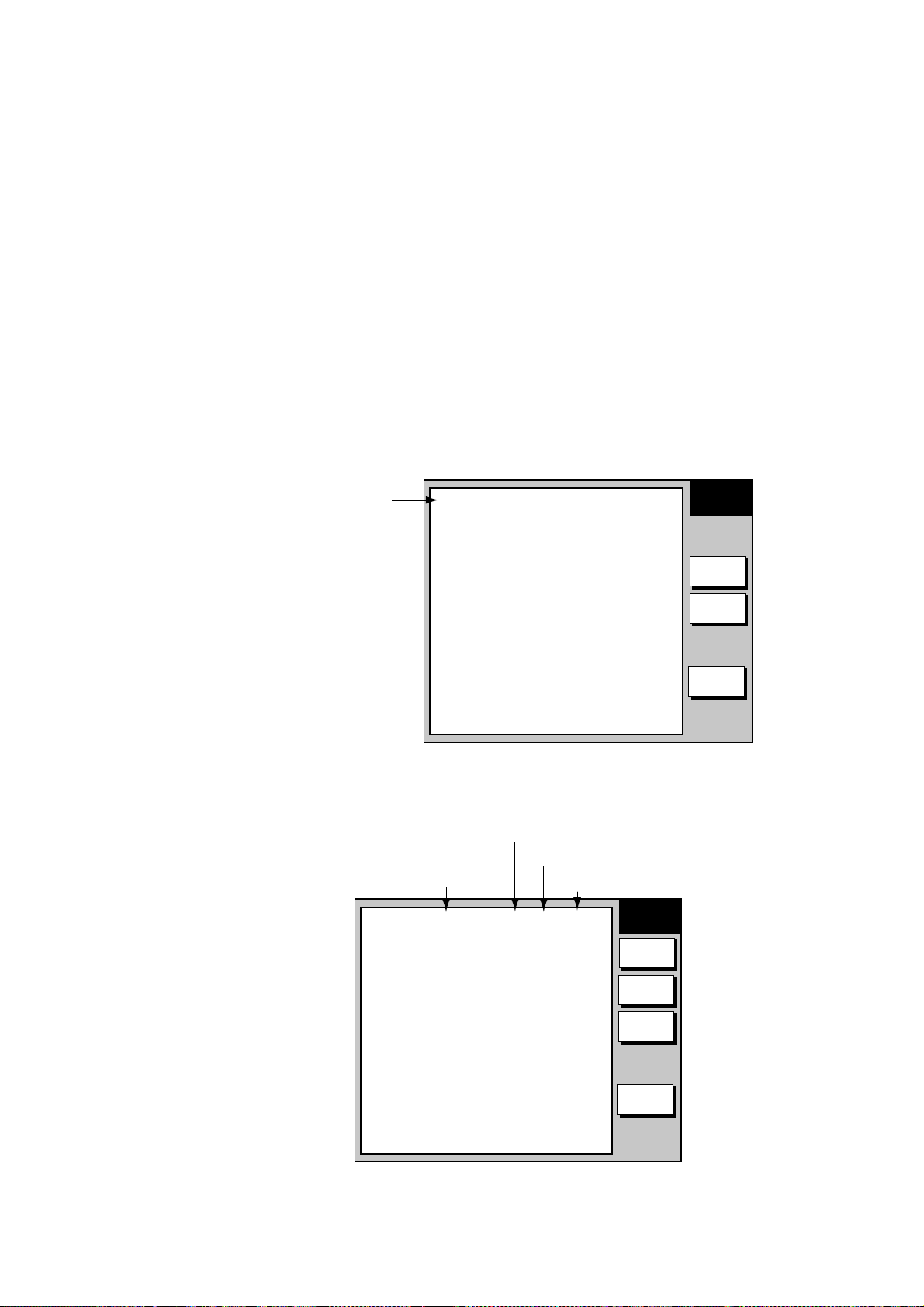
1. Press the [MENU] key to show the FAX-30 menu.
EDIT WX FAX STATION
EDIT NAVTEX STATION
FAX-30 SYSTEM SETUP
FAX-30 top
2. Press the EDIT WX FAX STATION soft key.
FAX-30
▲
ZONE
STATION
CHANNEL
REVERSE IMAGE NORMAL
FREQUENCY 00079.9 kHz
CALL SIGN PRV
STATION NAME
0
PRIVATE
0
PRV/
0
00079.9 kHz
- - - - - - - - - - - - -
Edit facsimile station menu
3. ZONE is selected; press the EDIT soft key.
ZONE
▲
¤
0
PRIVATE
1
NORTHWEST PACIFIC
¡
¡
2
NORTHEAST PACIFIC
¡
3
SOUTH PACIFIC/INDIAN
¡
4
SOUTH ATLANTIC
¡
5
NORTHWEST ATLANTIC
¡
6
NORTHEAST ATLANTIC
¡
7
NORTH ATLANTIC
▼
EDIT
STATION
EDIT
SAVE
RETURN
2-18
Zone options
4. Rotate the [ENTER] knob to choose a zone and push the EDIT soft key.
(Zone 0 and 9 are for user zones.)
offered by Busse-Yachtshop.com
Page 41

2. FAX OPERATION: NAVNET
5. Rotate the [ENTER] knob to choose STATION and press the EDIT soft key. If
the ZONE chosen at step 4 is “1 NORTHWEST PACIFIC,” for example, the
STATION options are as below.
STATION
▲
¤
0
JMH /TOKYO 1
1
JMJ /TOKYO 2
¡
¡
2
JJC /KYODO 9MG
¡
3
JFA /CHUO GYOGYOU
¡
4
3SD /BEIJING
¡
5
BAF /BEIJING
¡
6
BDF /SHANGHAI
¡
7
BMF /TAIPEI
▼
Station options (Example: stations of northwest pacific)
6. Rotate the [ENTER] knob to choose a station and press the ENTER soft key.
7. Rotate the [ENTER] knob to choose CHANNEL and press the EDIT soft key.
If the station chosen at step 8 is “0 JMH/TOKYO No.1,” for example, the
CHANNEL options are as below.
CHANNEL
▲
AUTO
¤
0
03622.5 kHz
¡
¡
1
04902.0 kHz
¡
2
07305.0 kHz
¡
3
09970.0 kHz
¡
4
13597.0 kHz
¡
5
18220.0 kHz
¡
6
23522.9 kHz
▼
Channel options (Example: JMH/Tokyo)
8. Rotate the [ENTER] knob to choose a channel and press the ENTER soft
key.
9. Rotate the [ENTER] knob to choose REVERSE IMAGE and press the EDIT
soft key.
REVERSE IMAGE
▲
¤
NORMAL
REVERSE
¡
▼
Reverse image options
10. The normal facsimile image format has black text on a white background.
Some stations, however, print white characters on a black background. This
information is programmed into the memory thus you need not designate
image format. However, if you are entering frequency data of a newly
established station whose image format is reverse of the normal image,
rotate the [ENTER] knob to choose REVERSE. Press the ENTER soft key
after making your selection.
2-19
offered by Busse-Yachtshop.com
Page 42

2. FAX OPERATION: NAVNET
11. If you want to enter a frequency, call sign or station name other than that
shown at CHANNEL and STATION, respectively, rotate the [ENTER] knob to
choose FREQUENCY, CALL SIGN or STATION NAME as appropriate and
press the EDIT soft key. One of the following displays appears depending on
your selection.
FREQUENCY
00003.4 kHz
Frequency Call Sign Station Name
CALL SIGN
JMH
STATION NAME
TOKYO
Frequency, call sign and station name entry windows
12. Use the alphanumeric keys or the [ENTER] knob to enter appropriate data
and press the ENTER soft key. You can shift the cursor by rotating the
trackball.
13. Press the SAVE soft key.
14. Rotate the trackball to choose YES and then push the [ENTER] knob.
15. Press the [MENU] key to close the menu.
2-20
offered by Busse-Yachtshop.com
Page 43

3. FAX OPERATION: PC
3.1 Automatic Receiving
3.1.1 Starting receiving
1. At the facsimile standby display, click CHANNEL SETUP on the top menu.
CHANNEL SETUP
ZONE
STATION
CHANNEL
FREQUENCY
OK
RCV STOP
< back
2. Click the arrow button on ZONE and choose desired zone.
3. Click the arrow button on STATION and choose desired station. See page
AP-2 for station number.
4. Click the arrow button on CHANNEL and choose desired channel. Choose
AUTO if you are unsure of channel. (Most stations transmit the same
message over several frequencies, so if you are unsure of the channel
choose AUTO.)
5. If necessary you may fine tune the frequency. Click anywhere inside the
FREQUENCY box and enter frequency.
6. Click OK and then click “<back” or Back button to return to the top menu.
Then, the FAX-30 will receive the next scheduled broadcast from the station
selected. When the FAX-30 receives the start signal from the facsimile station it
automatically adjusts itself to match speed, IOC (Index of Cooperation) and
phase of the station’s transmitter. After a facsimile image is received it is
compressed and stored in the image memory and then posted on the facsimile
standby display screen. This process takes 3-5 minutes.
3.1.2 Stopping receiving
1: NORTHWEST PACIFIC
0: JMH/TOKYO 1
AUTO
03622.5 kHz
Channel setup menu
You may stop receiving at any time by doing the following:
1. At the facsimile standby display, click CHANNEL SETUP on the top menu.
2. Click RCV STOP.
3-1
offered by Busse-Yachtshop.com
Page 44

3. FAX OPERATION: PC
3.2 Timer Receiving
Most facsimile stations transmit facsimile signals in accordance with a schedule
issued by relative meteorological observatory. (You can find facsimile schedules
in the publication “Meteorological Facsimile Broadcasts,” available through
meteorological observatory bodies.) If you wish to receive a certain facsimile
broadcast on a daily basis, therefore, the timer receiving mode will virtually allow
you “hands-off” automatic operation. 30 timer programs may be set.
3.2.1 Setting, changing timer receiving schedule
1. At the facsimile standby display, click TIMER SETUP followed by PROGRAM
LIST to show the timer schedule.
Facsimile station
TX frequency of facsimile station
Index Of Cooperation
Start,
end time
No. LIST ON/OFF
1 12:30-14:00 JMH 3662.5kHz IOC288 60rpm ON
2 NOT PROGRAMMED OFF
3 NOT PROGRAMMED OFF
4 NOT PROGRAMMED OFF
5 NOT PROGRAMMED OFF
6 NOT PROGRAMMED OFF
7 NOT PROGRAMMED OFF
8 NOT PROGRAMMED OFF
9 NOT PROGRAMMED OFF
10 NOT PROGRAMMED OFF
11 NOT PROGRAMMED OFF
12 NOT PROGRAMMED OFF
13 NOT PROGRAMMED OFF
14 NOT PROGRAMMED OFF
15 NOT PROGRAMMED OFF
16 NOT PROGRAMMED OFF
17 NOT PROGRAMMED OFF
18 NOT PROGRAMMED OFF
19 NOT PROGRAMMED OFF
20 NOT PROGRAMMED OFF
21 NOT PROGRAMMED OFF
22 NOT PROGRAMMED OFF
23 NOT PROGRAMMED OFF
24 NOT PROGRAMMED OFF
25 NOT PROGRAMMED OFF
26 NOT PROGRAMMED OFF
27 NOT PROGRAMMED OFF
28 NOT PROGRAMMED OFF
29 NOT PROGRAMMED OFF
30 NOT PROGRAMMED OFF
Timer program list
Drum rotation speed
at facsimile station
3-2
offered by Busse-Yachtshop.com
Page 45

3. FAX OPERATION: PC
2. Click the location in the center column of the timer program list corresponding
to the timer program no. you want to set. For example, click the center
column of No.2. The following timer program menu appears.
TIMER PROGRAM No.2
ZONE
STATI ON
CHANNEL
IOC
SPEED
START TIME
END TIME
FREQUENCY
OK
ERASE
< back
1: NORTHWEST PACIFIC
0: JMH/TOKYO 1
AUTO
AUTO
AUTO
00 00
00 00
00000.0 kHz
¡
ON ¤OFF
Timer program menu
3. Click the arrow button on ZONE and choose desired zone.
4. Click the arrow button on STATION and choose desired station.
5. Click the arrow button on CHANNEL and choose desired channel. (Most
stations transmit the same message over several frequencies, so if you are
unsure of the channel choose AUTO.)
6. Click the arrow button on IOC and choose desired IOC. IOC stands Index of
Cooperation and is the line density standard assigned by WMO: IOC 576,
high density, IOC 288, low density. If you are unsure of the IOC, choose
AUTO for automatic selection of IOC.
7. Click the arrow button on SPEED and choose desired speed. This is the
drum rotating speed at the facsimile station. If you are unsure of the speed,
choose AUTO for automatic selection of speed.
8. Key in the start time in 24-hour notation. Key in a start time about two
minutes earlier than actual start time to allow for detection of the start signal
and press the ENTER soft key.
9. Key in the end time in 24-hour notation and press the ENTER soft key. Key in
an end time about two minutes later than actual end time to allow for
detection of the stop signal.
Note: Two programs which overlap each other will cause the program having
the later start time to be disregarded. For example, if the start and end
times of program no. 1 are 01:00 and 02:00 and those of program no.
2 are 01:30 to 3:00, program no. 2 will be disregarded.
10. If necessary you may fine tune the frequency at FREQUENCY.
3-3
offered by Busse-Yachtshop.com
Page 46

3. FAX OPERATION: PC
11. Click ON below FREQUENCY.
12. Click OK.
13. Click “<back” or Back button several times to return to the top menu.
14. Repeat steps 1-13 to set other timer schedule.
15. At the facsimile standby display, click TIMER SETUP.
16. Click PROGRAM LIST.
17. Click START.
18. Click OK.
19. Click “<back” or Back button to return to the top menu.
Then, the FAX-30 will receive facsimile broadcasts according to the timer
schedule. Facsimile images are received line by line, taking 30-40 minutes to
receive depending on the size of the image and drum rotation speed at the
facsimile station. After a facsimile image is received it is compressed and stored
in the image memory and then posted on the facsimile standby display screen.
This process takes 3-5 minutes.
3.2.3 Turning on/off specific timer programs
1. At the facsimile standby display, click TIMER SETUP.
2. Click PROGRAM LIST.
3. Click the center column of the program no. you want to turn on or off.
4. Click ON or OFF as appropriate.
5. Click OK.
6. Click “<back” or Back button to return to the top menu.
3.2.4 Clearing all timer programs
You may clear all timer programs as follows:
1. At the facsimile standby display, click TIMER SETUP.
2. Click PROGRAM LIST.
3. Click CLEAR ALL at the top of the screen.
4. You are asked “Are you sure to clear all?”
5. Click Yes to reset; Cancel to escape.
6. Click “<back” or Back button to return to the top menu.
3-4
offered by Busse-Yachtshop.com
Page 47

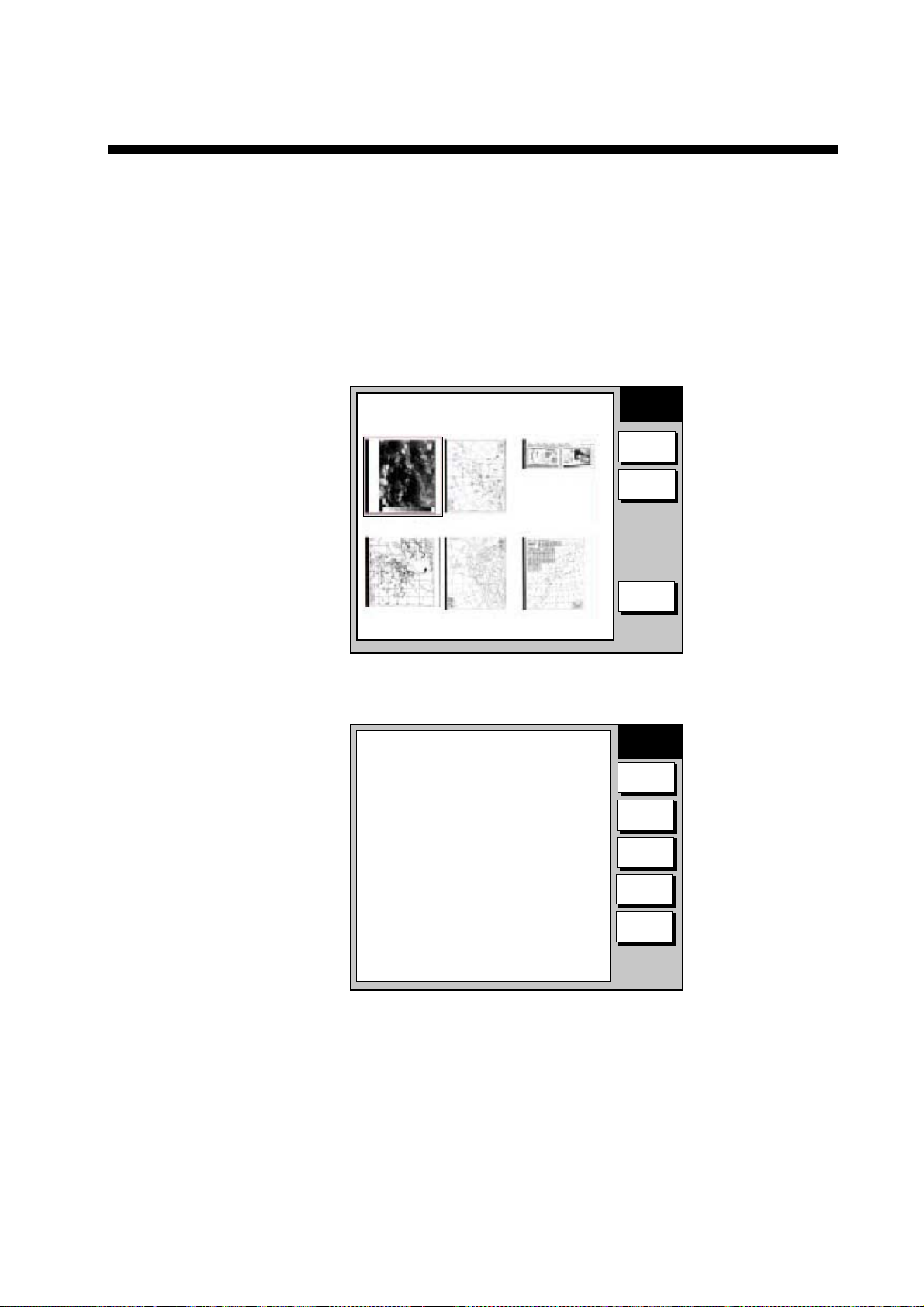
3.3 Displaying Facsimile Images
1. Show the facsimile standby display. Thumbnails of images received are
shown on the display. The equipment stores as many as 12 images, on two
pages. When the image storage capacity is exceeded, the oldest image is
automatically deleted to make room for the latest.
3. FAX OPERATION: PC
100N 3625.kHz
IOCXX10 XXXrpm
SS=XXX SN=XX
STBY
MENU
CHANNEL SETUP
TIMER SETUP
EDIT STATION LIST
SYSTEM SETUP
RX MODE
<< Top
JMH JUN/04 02:46 JMH JUN/05 01:29 JMH JUN/05 01:32
JMH JUN/05 03:46 JMH JUN/05 04:29 JMH JUN/05 05:21
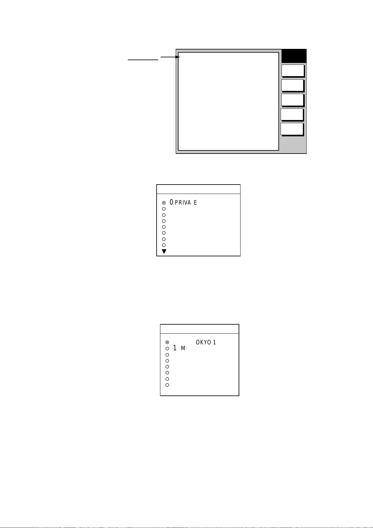
2. Click desired image.
Click to return to thumbnails display.
100N 3625.kHz
IOCXX10 XXXrpm
SS=XXX SN=XX
STBY
MENU
CHANNEL SETUP
TIMER SETUP
EDIT STATION LIST
SYSTEM SETUP
RX MODE
<<THUMBNAILS
ZOOM IN
ROTATE CW
PHASE
102N JMH 7305.0kHz IOC576 120rpm JUN/05 01:26
0
NEXT PAGE 1/2
Facsimile standby display
SYNC
10
ROTATE CCW
NOISE REJECT
LOCK
30
ERASE
REVERSE IMAGE
40
COLOR
20
Click NEXT PAGE to
go to next page.
Receive data
Station, date and
time image received
Image processing functions
Click to execute. See para. 3.4.
Scale
Used for phase tuning.
See para. 3.4.1.
<< Top
Image data
102N: Zone
JMH: Station
7305.0 kHz: Channel
IOC576: Index of Cooperation
120 rpm: Drum speed at fax station
JUN/05: Date received
01:26: Time received
Facsimile image
Note: If the FAX-30 is not accessed from the PC after it has been turned on,
time data is not sent to the FAX-30. The timer recording feature may
receive a facsimile image using incorrect time data, however the image
may not be correctly stored.
3-5
offered by Busse-Yachtshop.com
Page 48

3. FAX OPERATION: PC
3.4 Processing Facsimile Imag es
3.4.1 Phase mismatch
When the FAX-30 starts receiving a broadcast already in progress, or noise
prevents detection of the phasing signal, the image may be divided into two
parts by a thick black (or white) stripe called a dead sector. This phenomenon is
due to phase mismatching. When this occurs, correct phase mismatching, after
the facsimile has been received.
0
10 20 30 40
Dead sector (can be white)
Dead sector
center at "15"
Example of phase mismatching
1. With a facsimile image displayed, click PHASE.
PHASE
0
OK
< back
Phase entry window
2. Read the scale to find the center of the dead sector and enter it in the phase
entry window. For example, if dead sector is centered at "15" on the scale, as
in the illustration at the top of the page, enter “15”. The setting range is 00 to
40.
3. Click OK and then click “<back” or Back button to return to the top menu.
3-6
offered by Busse-Yachtshop.com
Page 49

3.4.2 Phasing signal out of synchronization
The SYNC soft key functions to fine tune the phasing signal. If the dead sector is
plotted at an angle even when the phase is properly selected, adjust the
synchronization to display the dead sector straightly.
Example of phasing signal out of synchronizati o
1. With a facsimile image displayed, click SYNC.
SYNC
0
3. FAX OPERATION: PC
2. Enter a sync value that displays the dead sector straightly and then click OK.
If the dead sectors appears as in the left-hand figure above, enter a larger
value and for the right-hand figure, enter a smaller value. The setting range
is –50 to +50.
3. Click OK and then “<back” or Back button to return to the top menu.
3.4.3 Noise rejection
If noise speckles appear on the image, turn on the noise rejector as below to
remove the noise.
1. With a facsimile image displayed, click NOISE REJECT.
OK
< back
Sync options
NOISE REJECT
OFF
LOW
MEDIUM
HIGH
OK
< back
Noise rejector options
2. Click the noise rejection level desired and then click OK. HIGH provides the
greatest degree of noise rejection.
3. Click OK and then “<back” or Back button to return to the top menu.
3-7
offered by Busse-Yachtshop.com
Page 50

3. FAX OPERATION: PC
3.4.4 Image color
The facsimile image is transmitted in monochrome (black and white) or gray
scale (16 gradations). After an image has been received, you can choose the
color arrangement among monochrome, gray scale and color (three patterns).
1. With a facsimile image displayed, click COLOR.
COLOR
MONOCHROME
GRAY SCALE
BLUE-RED
WHITE-BLUE
PINK-BLACK
OK
< back
2. Click MONOCHROME, GRAY SCALE, BLUE-RED, WHITE-BLUE or
PINK-BLACK as appropriate.
MONOCHROME: Monochrome black and white
GRAY SCALE: 16 gray tones (eight gray tones when power is turned off
BLUE-RED: Shades of blue to red
WHITE-BLUE: Shades of white to blue
PINK-BLACK: Shades of pink to black
3. Click OK and then click “<back” or Back button to return to the top menu.
3.4.5 Image format
The facsimile image is usually transmitted with black text on a white background.
Some stations, however, print white characters on a black background. If, for
some reason, the image received cannot be read in its transmitted image format
you may change it as follows:
1. With a facsimile image displayed, click REVERSE IMAGE.
Color options
and on again)
3-8
REVERSE IMAGE
NORMAL
REVERSE
OK
< back
Reverse image options
2. Click NORMAL or REVERSE as appropriate.
3. Click OK and then click “<back” or Back button to return to the top menu.
offered by Busse-Yachtshop.com
Page 51

3.4.6 Rotating images
With a facsimile image displayed, click ROTATE CW or ROTATE CCW as
appropriate. The image is rotated 90° in the direction selected.
3.4.7 Zooming images
You may double the size of a facsimile image as follows:
1. Display the facsimile image you wish to process.
2. Click ZOOM IN.
To restore the normal size image, click ZOOM OUT.
3.4.8 Saving images
You may save images to your PC for future reference.
1. At the thumbnails display, click the facsimile image you wish to save.
2. Click ZOOM IN to enlarge the image. (The image is too small if not
enlarged.)
3. Place the cursor on the facsimile image and click the right button on the
mouse.
4. Click the “Save Picture As…” The “Save” window appears.
5. Choose directory, enter file name and click the Save button.
3. FAX OPERATION: PC
3.5 Erasing Facsimile Images
You may erase facsimile images as below.
1. Display the facsimile image you wish to erase.
2. Click ERASE.
3. You are asked if you are sure to erase the image. Click OK to erase the
image; Cancel to escape.
3-9
offered by Busse-Yachtshop.com
Page 52

3. FAX OPERATION: PC
3.6 Preventing Erasure of Facsimile Images
When facsimile image storage capacity is exceeded, the oldest facsimile image
is erased to make room for the latest. If you have an image which you want to
keep, you can prevent its erasure by using the “lock” feature. You can lock all
images, however you may not be able to receive a new image if there is not
sufficient memory remaining to store the new image.
1. Display the facsimile image you want to lock.
2. Click LOCK.
LOCK
ON
OFF
OK
< back
Lock options
3. Choose ON.
4. Click OK and then click “<back” or Back button to return to the top menu.
The locked image’s data appears in red, at the facsimile standby display. To
release the lock feature for a particular image, choose OFF at the step 3 in the
above procedure.
3-10
offered by Busse-Yachtshop.com
Page 53

3.7 Adding Facsimile Channels
The FAX-30 provides a free memory for the user to store 320 channels.
1. At the standby display, click EDIT STATION LIST.
EDIT STATION LIST
3. FAX OPERATION: PC
ZONE
STATION
CHANNEL
REVERSE
IMAGE
FREQUENCY
CALL SIGN
STATI ON
NAME
OK
< back
0: PRIVATE
0: PRV/
0: 79.9 kHz
NORMAL
79.9 kHz
PRV
Edit station list menu
2. Click the arrow button on ZONE and choose desired zone.
3. Click the arrow button on STATION and choose desired station.
4. Click the arrow button on CHANNEL and choose desired image format.
5. The normal facsimile image format has black text on a white background.
Some stations, however, print white characters on a black background. This
information is programmed into the memory thus you need not designate
image format. However, if you are entering frequency data of a newly
established station whose image format is reverse of the normal image,
choose REVERSE.
6. If necessary, you may fine tune the frequency shown in FREQUENCY.
7. Enter station’s CALL SIGN.
8. Enter STATION’S NAME.
9. Click OK.
9. Click “<back” or Back button to return to the top menu.
3-11
offered by Busse-Yachtshop.com
Page 54

3. FAX OPERATION: PC
(This page intentionally left blank.)
3-12
offered by Busse-Yachtshop.com
Page 55

4. NAVTEX OPERATION: NAVNET
4.1 About Navtex Messages
4.1.1 Message categories
Navtex stations throughout the world provide mariners with weather and
navigational navtex messages. These messages carry a four character header
code which identifies transmitting station, category of message, and message
number, numbered from 00 to 99. Message number 00 is reserved for important
emergency messages. The categories of messages available in the navtex
system are as below.
A: Coastal navigational warning H: Loran message
B: Meteorlogical warning I: Omega message
C: Ice report J: Differential Omega message
D: Search and Rescue Alert K: Other electronic navigator system message
E: Meteorological forecast L: Navarea warnings
F: Pilot message V to Y: No category allocated
G: Decca message Z: QRU (no message on hand)
The user may select which message categories to receive and the stations from
which to receive them.
Note: It is recommended to minimally receive categories A, B, D and L because
they are important for navigation.
4.1.2 Receiving navtex messages
To receive navtex messages, set the receive mode for “navtex only” or
“fax(timer) & navtex”, referring to paragraph 1.1.3 for the procedure.
4-1
offered by Busse-Yachtshop.com
Page 56

4. NAVTEX OPERATION: NAVNET
4.2 Setting Up Navtex Stations, Messages, Alarms
You may freely select the navtex stations from which to receive and the
messages categories to receive. Further, you may enable or disable received
message alarms.
1. At the standby display, press the NAVTEX soft key. If you have received
some navtex messages, their data are shown as below.
▲
1. IA55 JUN/06 03:57 518kHz
2. IA53 JUN/06 03:58 518kHz
3. IA52 JUN/06 03:59 518kHz
4. IA48 JUN/06 04:01 518kHz
Navtex message data display
2. Press the RX SETUP soft key.
▲
FREQUENCY 518 kHz
STA. SELECTION MODE MANUAL
STATION SELECTION .
MESSAGE SELECTION
MAX ERROR RATE 33%
ALARM (SAR MSG) OFF
ALARM (WARNING MSG) OFF
NAVTEX
SELECT
MSG
RCV
NAVTEX
RX
SETUP
RETURN
Appears when the mode is
NAVTEX or FAX(TIMER)&NAVTEX
RX
SETUP
EDIT
RETURN
RX setup menu
3. FREQUENCY is selected, press the EDIT soft key.
FREQUENCY
▲
¤
490 kHz
518 kHz
¡
▼
Navtex frequency options
4. Rotate the [ENTER] knob to choose 490 kHz or 518 kHz depending on the
station and press the ENTER soft key.
4-2
offered by Busse-Yachtshop.com
Page 57

4. NAVTEX OPERATION: NAVNET
5. Rotate the [ENTER] knob to choose STA. SELECTION MODE and press the
EDIT soft key.
STA. SELECTION MODE
▲
¡
MANUAL
AUTO
¤
▼
Navtex station mode options
6. Rotate the [ENTER] knob to choose navtex station selection method and
press the [ENTER] soft key. AUTO requires position data, output through the
network using the data sentence GGA or GLL. (See page 1-2.)
7. If you selected MANUAL at step 6, rotate the [ENTER] knob to choose
STATION SELECTION and press the EDIT soft key, to choose station(s)
from which to receive. For AUTO, go to step 9.
STATION SELECTION
▲
A
B
C
D
E
F
G
H
▼
Navtex station options
8. Select or deselect stations as desired: Rotate [ENTER] knob to choose
station and push it to select or deselect. Check mark indicates station is
selected; no check mark means deselected.
9. Press the ENTER soft key to return the RX SETUP menu.
10. Rotate the [ENTER] knob to choose MESSAGE SELECTION and press the
EDIT soft key.
MESSAGE SELECTION
▲
A NAVIGATIONAL WARNING
B METEOR. WARNING
C ICE REPORT
D SAR INFORMATION
E METEOR. FORECAST
F PILOT MESSAGE
G DECCA MESSAGE
H LORAN MESSAGE
▼
Navtex message options
11. Select or deselect message categories as desired: Rotate [ENTER] knob to
choose message category and push it to select or deselect. Check mark
indicates message is selected; no check mark means deselected.
12. Press the ENTER soft key.
13. Rotate the [ENTER] knob to choose MAX ERROR RATE and press the EDIT
soft key.
4-3
offered by Busse-Yachtshop.com
Page 58

4. NAVTEX OPERATION: NAVNET
14. Rotate the [ENTER] knob to enter maximum allowable error rate to use. The
setting range is 0-33%. Any message with an error rate higher than that
entered here will be rejected.
15. Press the ENTER soft key.
16. Rotate the [ENTER] knob to choose ALARM (SAR MSG) and press the EDIT
soft key.
MAX ERROR RATE
33%
Max error rate entry window
ALARM (SAR MSG)
▲
¡
ON
¤
OFF
▼
Alarm (SAR MSG) options
17. Rotate the [ENTER] knob to choose ON to get the audio alarm when an SAR
(Search and Rescue) message is received, or OFF for no audio alarm when
an SAR message is received.
Note: Message category D must be selected to get the audio alarm.
18. Press the ENTER soft key.
19. Rotate the [ENTER] knob to choose ALARM (WARNING MSG) and press the
EDIT soft key.
ALARM (WARNING MSG)
▲
¡
ON
¤
OFF
▼
Alarm (warning msg) options
20. Rotate the [ENTER] knob to choose ON to get the audio alarm when an A, B,
or L category message is received, or choose OFF for no audio alarm.
Note: Message category A, B or L must be selected to get the audio alarm.
21. Press the [RETURN] soft key.
Note: When the above alarms are enabled, the audio alarm sounds and the
speaker icon (
) appears when an SAR message or category A, B, D or L
message is received. Press the [CLEAR] key to silence the audio alarm.
You can see which type of message you have received by pressing the
[ALARM] key to display the alarm message board.
4-4
offered by Busse-Yachtshop.com
Page 59

4. NAVTEX OPERATION: NAVNET
4.3 Previewing Incoming Navtex Messages
If you want to view a navtex message while it is being received, do the following:
1. At the standby display, press the NAVTEX soft key. If no messages have
been received the display shows “NO RECEIVED MESSAGES AVAILABLE.”
NAVTEX
SELECT
MSG
RCV
NAVTEX
RX
SETUP
RETURN
Navtex message selection screen
2. Press the RCV NAVTEX soft key.
RECEIVE
NAVTEX
RETURN
Message
being
received
518kHz MANUAL* SS=52 RCV
ZCZC IA55
160520 UTC JUNE 05
JAPAN NAVTEX N.W. NR 0775/2002
* =
"AUTO LAT/LON" and OK or NG (No Good)
shown in automatic reception.
Navtex message preview display
3. Press the RETURN soft key several times to return to standby display.
4-5
offered by Busse-Yachtshop.com
Page 60

4. NAVTEX OPERATION: NAVNET
4.4 Displaying Navtex Messages
4.4.1 Displaying navtex messages
1. At the standby display, press the NAVTEX soft key.
Station ID, Category, No.
Date received
Time received
Frequency
▲
1. IA55 JUN/06 03:57 518kHz SAR*
2. IA53 JUN/06 03:58 518kHz NEW#
3. IA52 JUN/06 03:59 518kHz NEW
4. IA48 JUN/06 04:01 518kHz NEW
NAVTEX
SELECT
MSG
RCV
NAVTEX
RX
SETUP
RETURN
* = "SAR" denotes SAR message.
# = NEW means unread message, and it disappears when
the power is turned off.
Navtex message selection screen
2. Rotate the [ENTER] knob to choose the message to display.
3. Press the SELECT MSG soft key or push the [ENTER] knob.
Station ID (I), Category (A), Message No. (55)
Date received
Time received
Frequency
Error Rate
SELECT
MSG
RETURN
Message
1
A55 JUN/05 03:57 518kHz ERROR RATE=0.0%
ZCZC IA55
160520 UTC JUNE 05
JAPAN NAVTEX N.W. NR 0775/2002
ASHIKURI MISAKI, SOUTHWARD.
FLARE DROPPING. 150930Z TO 151100Z JUNE,
ALTERNATE 160930Z TO 161100Z JUNE.
WITHIN 10 MILES OF 31-00N 133-00E.
GEODETIC DATUM UNKNOWN.
NNNN
Sample navtex message
4. Press the RETURN soft key several times to return to the standby display.
4-6
offered by Busse-Yachtshop.com
Page 61

4.4.2 Remarks on navtex messages
• All navtex messages begin with “ZCZC” (navtex message ID) and end with
“NNNN”. Immediately following ZCZC, the transmitting station ID, message
category and message number are shown. In the example illustration at the
bottom of the previous page this data is “IA55.”
I = Transmitting station’s ID
A = Message category
55 = Message number
• An asterisk (*) is displayed in place of actual character when the character
could not be read.
• Message number 00 contains important emergency information.
• The FAX-30 holds 130 navtex messages. When the navtex message storage
capacity is exceeded, the oldest navtex message is automatically deleted to
make room for the latest.
4. NAVTEX OPERATION: NAVNET
4-7
offered by Busse-Yachtshop.com
Page 62

4. NAVTEX OPERATION: NAVNET
4.5 Displaying the Navtex Station List
You may display the navtex stations stored in the FAX-30, as follows:
1. Press the [MENU] key to open the FAX-30 menu.
2. Press the EDIT NAVTEX STATION soft key.
3. Press the 490 kHz STATION LIST soft key or the 518 kHz STATION LIST soft
key as appropriate. The illustration below shows the nav areas for 490 kHz.
▲
NAV AREA 01 UNITED KINGDOM
NAV AREA 02 FRANCE
NAV AREA 03 SPAIN
NAV AREA 04 U.S.A.
NAV AREA 05 BRAZIL
NAV AREA 06 ARGENTIA
NAV AREA 07 SOUTH AFRICA
NAV AREA 08 INDIA
NAV AREA 09 PAKISTAN
NAV AREA 10 AUSTRALIA
NEXT PAGE
NAVAREA
EDIT
RETURN
Nav areas for 490 kHz navtex stations
4. Choose nav area desired and push the [ENTER] knob. For example, choose
nav area 0I of 490 kHz to show the 490 kHz station list.
(To choose nav area 11 to 16, choose NEXT PAGE and push the [ENTER]
knob.)
▲
I, U 55°02’N 001°26’W CULLERCOATS
C 54
°
51’N 005°07’W PORTPATRICK
°
35’N 001°18’W NITON
I, T 30
STATION
LIST
EDIT
RETURN
490 kHz stations of nav area I
5. If you want to view or edit the contents of a navtex station, rotate the
[ENTER] knob to choose a station and press EDIT soft key. Follow the
instructions in the previous paragraph to edit a station.
6. Press the [MENU] key to return to the standby screen.
4-8
offered by Busse-Yachtshop.com
Page 63

4.6 Adding Navtex Stations
You may add newly established navtex stations to the navtex station list as
follows:
1. Press the [MENU] key to open the FAX-30 menu.
2. Press the EDIT NAVTEX STATION soft key.
ADD NAVTEX STATION
518 kHz STATION LIST
490 kHz STATION LIST
4. NAVTEX OPERATION: NAVNET
EDIT
STATION
RETURN
Edit station menu
3. Press the ADD NAVTEX STATION soft key.
▲
NAV AREA 01
STATION NAME _ _ _ _ _ _ _ _ _ _
518 kHz STATION ID1 _
518 kHz STATION ID2 _
490 kHz STATION ID1 _
490 kHz STATION ID2 _
LATITUDE 00
LONGITUDE 000
°
00’ N
°
00’ E
Edit navtex station menu
4. NAV AREA is selected; press the EDIT soft key.
NAV AREA
EDIT
STATION
EDIT
SAVE
RETURN
▲
01
▼
Nav area selection window
5. Choose appropriate area, referring to the navtex station map in the Appendix,
and press the ENTER soft key.
4-9
offered by Busse-Yachtshop.com
Page 64

4. NAVTEX OPERATION: NAVNET
6. Rotate the [ENTER] knob to choose STATION NAME and press the EDIT
soft key.
7. Enter station name with the alphanumeric keys and trackball and then press
the ENTER soft key.
8. Rotate the [ENTER] knob to choose 518 STATION ID1 or 490 STATION ID1
as appropriate and press the EDIT soft key.
STATION NAME
_ _ _ _ _ _ _ _ _ _
Station name entry window
518 kHz STATION ID1
_
Station ID1 entry window
9. Enter station ID (A-Z) and press the ENTER soft key.
10. If there are multiple stations, enter station ID in 518 kHz STATION ID2 or 490
kHz STATION ID2 as appropriate.
11. Rotate the [ENTER] knob to choose LATITUDE and press the EDIT soft key.
LATITUDE
00°00' N
Latitude entry window
12. Enter the latitude of the station and press the ENTER soft key. Use the
[N↔S] soft key to switch from North latitude to South latitude and vice versa.
13. Rotate the [ENTER] knob to choose LONGITUDE and press the EDIT soft
key. Enter longitude of the station similar to how you entered latitude. Use
the [W↔E] soft key to switch from West longitude to East longitude and vice
versa.
14. Press the SAVE soft key.
15. Rotate the [ENTER] knob to choose YES and then push the [ENTER] knob.
16. Press the [MENU] key to close the menu.
4-10
offered by Busse-Yachtshop.com
Page 65

5. NAVTEX OPERATION: PC
5.1 About Navtex Messages
5.1.1 Message categories
Navtex stations throughout the world provide mariners with weather and
navigational navtex messages. These messages carry a four character header
code which identifies transmitting station, category of message, and message
number, numbered from 00 to 99. Message number 00 is reserved for important
emergency messages. The categories of messages available in the navtex
system are as below.
A: Coastal navigational warning H: Loran message
B: Meteorlogical warning I: Omega message
C: Ice report J: Differential Omega message
D: Search and Rescue Alert K: Other electronic navigator system message
E: Meteorological forecast L: Navarea warnings
F: Pilot message V to Y: No category allocated
G: Decca message Z: QRU (no message on hand)
The user may select which message categories to receive and the stations from
which to receive them.
Note 1: It is recommended to minimally receive categories A, B, D and L
because they are important for navigation.
Note 2: To learn more about navtex messages, see paragraph 4.4.2.
5.1.2 Receiving navtex messages
To receive navtex messages, set the receive mode for “navtex only” or “fax &
navtex”, referring to paragraph 1.2.2 for the procedure.
5-1
offered by Busse-Yachtshop.com
Page 66

5. NAVTEX OPERATION: PC
5.2 Setting Up Navtex Stations, Messages
You may freely select the navtex stations from which to receive and the
messages categories to receive as follows:
1. At the navtex top menu, click RX SETUP.
RX SETUP
FREQUENCY
STATION
SELECTION
MODE
STATION ID SELECTION
AB CD
EF GH
IJKL
MN O P
QR S T
UV WX
Y Z
490 kHz STATION LIST
518 kHz STATION LIST
MESSAGE ID SELECTION
AB CD
EF GH
IJKL
MN O P
QR S T
UV WX
518 kHz
MANUAL
Y Z
MESSAGE LIST
MAX. ERROR
RATE (033%)
OK
< back
33
%
RX setup menu
2. Click the arrow button on FREQUENCY and choose desired frequency.
3. Click the arrow button on STATION SELECTION MODE and choose desired
mode, AUTO or MANUAL.
AUTO requires connection to the NavNet network and is not available in the
PC-only configuration. The FAX-30 requires position data (data sentence
GGA or GLL) and time data (data sentence ZDA), fed through the NavNet
network.
5-2
offered by Busse-Yachtshop.com
Page 67

4. Click desired stations in STATION ID SELECTION. Check mark indicates
item is selected. (If you need help with station selection, click 490 kHz
STATION LIST or 518 kHz STATION LIST for details.)
5. Check desired messages in MESSAGE ID SELECTION. Check mark
indicates item is selected. (If you need help with message selection, click
MESSAGE LIST for details.)
6. At MAX. ERROR RATE, enter the maximum allowable error rate to use. The
setting range is 0-33 (%). Any message with an error rate higher than entered
here will be rejected.
7. Click OK and then click “<back” or Back button to return to the top menu.
5.3 Displaying Navtex Messages
At the navtex standby display, click the desired message number at the top of
the display.
Received messages (click to display)
5. NAVTEX OPERATION: PC
518kHz
AUTO LAT/LON OK
SS=10
STBY
MENU
RX SETUP
EDIT STATION LIST
SYSTEM SETUP
RX MODE
<< Top
1. 1A55 06/22 00:26 518kHz ERROR RATE=0.0%
2. 1A55 06/20 01:22 518kHz ERROR RATE=0.0%
3. 1A55 06/18 15:31 518kHz ERROR RATE=0.0%
4. 1A55 06/17 07:11 518kHz ERROR RATE=0.0%
5. 1A55 06/15 03:44 518kHz ERROR RATE=0.0%
1A55 06/05 03:57 518kHz ERROR RATE=0.0%
ZCZC IA55
160520 UTC JUNE 05
JAPAN NAVTEX N.W. NR 0775/2002
ASHIKURI MISAKI, SOUTHWARD.
FLARE DROPPING. 150930Z TO 151100Z JUNE,
ALTERNATE 160930Z TO 161100Z JUNE.
WITHIN 10 MILES OF 31-00N 133-00E.
GEODETIC DATUM UNKNOWN.
NNNN
NEXT PAGE 1/2
PREV NEXT
Use scroll bar
to scroll list.
Navtex message data
IA55: Station ID (I), Category (A),
Message No. (55)
06/05: Date received
03:57: Time received
518kHz: Frequency
Error rate
Text of message
Navtex standby display
5-3
offered by Busse-Yachtshop.com
Page 68

5. NAVTEX OPERATION: PC
5.4 Displaying the Navtex Station List
You may display the navtex stations stored in the FAX-30 as follows:
1. At the navtex top menu, click EDIT STATION LIST.
2. Click 490 kHz STATION LIST or 518 kHz STATION LIST as appropriate. The
illustration below shows the 490 kHz list.
490kHz STATION LIST
NAVAREA
I, U 55°02’N 001°26’W CULLERCOATS
S54°51’N 005°07’W PORTPATRICK
I, T 50°35’N 001°18’W NITON
1: UNITED KINGDOM
STATION LIST
Navtex station list
3. Pull down the arrow button on NAVAREA to choose nav area desired.
5-4
offered by Busse-Yachtshop.com
Page 69

5.5 Adding Navtex Stations
You may add newly established navtex stations to the navtex station list as
follows:
1. At the navtex standby display, click EDIT STATION LIST.
EDIT STATION LIST
5. NAVTEX OPERATION: PC
NAVAREA
STATION
NAME
518kHz
STATION ID1
518kHz
STATION ID2
490kHz
STATION ID1
490kHz
STATION ID2
LATITUDE
LONGITUDE
ADD
CANCEL
490 kHz STATION LIST
518 kHz STATION LIST
I
00 00
000
00
N
E
< back
Edit station list
2. Click the arrow button on NAVAREA and choose desired navarea.
3. Enter the station name in STATION NAME.
4. Enter station ID (A-Z) in STATION ID1 (and STATION ID2 if it has two IDs).
5. Enter latitude and longitude position of station.
6. Click ADD to register data entered.
7. To register another station, click NEW and repeat steps 2-6.
8. Click “<back” or Back button to return to the navtex top menu.
5-5
offered by Busse-Yachtshop.com
Page 70

5. NAVTEX OPERATION: PC
5.6 Editing Navtex Stations
You may edit navtex stations as follows:
1. At the navtex standby display, click EDIT STATION LIST.
2. Click 490 kHz STATION LIST or 518 kHz STATION LIST, whichever you want
to process. For example, click 490 kHz STATION LIST.
3. Click the arrow button on NAVAREA and choose desired navarea. For
example, choose UNITED KINGDOM.
4. In the station list, click the station to process. For example, click
CULLERCOATS.
EDIT STATION LIST
If you want to register a new
station from this screen, click
NEW. The screen shown on
page 5-5 appears. Follow the
procedure on page 5-5.
NAVAREA
STATION
NAME
518kHz
STATION ID1
518kHz
STATION ID2
490kHz
STATION ID1
490kHz
STATION ID2
LATITUDE
LONGITUDE
SAVE
CANCEL ERASE
NEW
490 kHz STATION LIST
518 kHz STATION LIST
I
CULLERCOATS
G
I
U
55 02
001
26
N
W
< back
Edit station list
5. Edit the data.
6. Click SAVE to save data.
7. Click “<back” or Back button to return to the navtex top menu.
5-6
offered by Busse-Yachtshop.com
Page 71

5.7 Deleting Navtex Stations
You may delete navtex stations from the navtex station list as below.
1. At the navtex standby display, click EDIT STATION LIST.
2. Click 490 kHz STATION LIST or 518 kHz STATION LIST, whichever you want
to process.
3. Click the arrow button on NAVAREA and choose desired navarea.
4. In the station list, click the station to process.
5. Click ERASE.
6. Click OK to erase the station, or the Cancel button to escape.
7. Click “<back” or Back button to return to the navtex top menu.
5. NAVTEX OPERATION: PC
5-7
offered by Busse-Yachtshop.com
Page 72

5. NAVTEX OPERATION: PC
(This page intentionally left blank.)
5-8
offered by Busse-Yachtshop.com
Page 73

6. MAINTENANCE, TROUBLESHOOTING
WARNING
ELECTRICAL SHOCK HAZARD
Do not open the equipment.
Only qualified personnel
should work inside the
equipment.
6.1 Maintenance
This unit is designed and manufactured to provide many years of trouble-free
performance. However, no machine can perform to the utmost of its ability
unless properly maintained. A maintenance program should be established and it
should include the items listed in the table below.
Maintenance points
Check Point Action
Whip antenna Check for damage. Replace if damaged.
Antenna wire Check for damage. Replace if damaged.
Junction between
whip antenna and
preamp (option)
Coaxial cable Check for damage and tight connection. Replace if damaged.
Power cable Check for tight connection at battery and FAX-30.
Ground terminal Check for tight connection and corrosion. Replace if corroded.
Unit cleanliness Dust and dirt should be removed with a soft cloth. Do not use
Check for corrosion and tight connection. Clean and
waterproof with sealing compound if necessary.
solvents such as benzine and toulene to clean the unit – they
can remove paint and markings or deform the equipment.
6-1
offered by Busse-Yachtshop.com
Page 74

6. MAINTENANCE, TROUBLESHOOTING
6.2 Replacement of Fuse
The 2A fuse in the power cable protects the equipment from equipment fault and
reverse polarity of the ship’s mains. If the fuse blows find the cause before
replacing it. If it blows again after replacement, contact your dealer for advice.
CAUTION
Use the proper fuse.
Use of a wrong fuse may cause
serious damage to the equipment
and void the warranty.
6.3 Troubleshooting
This section provides simple troubleshooting that the user may follow to restore
normal operation.
Troubleshooting
Trouble Problem Remedy
NavNet display unit
freezes
Command from
NavNet display unit
not accepted
Cannot read
characters
Noise but no signal • Loosened antenna
Multiple or overlapped
image
Image is split. • Image is out of phase. • Set phase manually.
Image is shrunk (or
enlarged) vertically.
Image is filled with
noise.
Timer schedule does
not start as
scheduled.
Cannot access
FAX-30 from PC.
• Jumbled memory
• Network not connected • Reselect the FAX mode.
• Corrupted memory • Clear memory.
connector
• Coaxial cable in antenna
cable is shorted or
damaged.
• Wrong speed setting • Set correct speed. Speed
• Wrong IOC • Change IOC. IOC may be
• Noise • Use the noise rejector to
• Improper setting of
schedule
• Incorrect IP address or
subnet mask set on PC.
• Turn the NavNet display unit
off and on again.
• Fasten antenna connector.
• Replace antenna cable.
may be adjusted when
manually receiving an
image.
adjusted when manually
receiving an image.
remove noise.
• Review schedule.
• Check setting referring to
page 7-8.
6-2
offered by Busse-Yachtshop.com
Page 75

6.4 Diagnostics: NavNet
The diagnostics test displays program no. and tests the ROMs, RAM, receive
ability, signal strength, signal-to-noise ratio and position data. The test results
are displayed as OK or NG (No Good) for ROM, RAM, receive ability and
position data. For any NG or abnormal value, contact your dealer for advice.
1. Press the [MENU] key to show the FAX-30 menu.
EDIT WX FAX STATION
EDIT NAVTEX STATION
FAX-30 SYSTEM SETUP
6. MAINTENANCE, TROUBLESHOOTING
FAX-30
FAX-30 menu
2. Press the FAX-30 SYSTEM SETUP soft key.
TEST
SIMULATION SETUP
CLEAR MEMORY
System setup menu
SYSTEM
SETUP
6-3
offered by Busse-Yachtshop.com
Page 76

6. MAINTENANCE, TROUBLESHOOTING
3. Press the TEST soft key to start the test. The test results appears as shown
below.
PROGRAM NO. 0850188-XX
Asterisk marks item
currently being tested
* ROM1 : OK
ROM2 : OK
SDRAM : OK
RECEIVE UNLOCK : OK
SS*1 : 60
SN*2 : 60
LAT/LON*3 : OK
Diagnostic test results
4. Press the RETURN key to escape from the test.
6.5 Diagnostics: PC
The diagnostics test displays program no. and tests the ROMs and RAM,
receive ability and position data. The test results are displayed as OK or NG (No
Good). For any NG or abnormal value, contact your dealer for advice.
1. At the facsimile or navtex standby display, click FAX-30 SYSTEM SETUP.
2. Click TEST. The test results appears as shown below.
0850189-XX
TEST
RETURN
XX = Version no.
*1 SS = Signal Strength
Display Range: 0-99
Typical Reading: 30-70
*2 SN = Signal-to-Noise Ratio
Display Range: 0-99
Typical Reading: 20-60
*3 Requires data sentence
GGA or GLL, output
through the network.
PROGRAM
NO.
0850188-XX.XX
0850189-XX.XX
XX.XX = Program Version No.
ROM1 OK
ROM2 OK
SDRAM OK
RECEIVE
UNLOCK
OK
LAT/LON* OK * = Requires data sentence GGA or GLL.
Diagnostic test results
3. Click STOP TEST to stop the test and restore normal operation and enable
receiving.
4. Click “<back” or Back button several times to return to the top menu.
6-4
offered by Busse-Yachtshop.com
Page 77

6.6 Clearing Data: NavNet
You may clear all facsimile images, navtex messages and the entire memory
contents to start afresh.
1. Press the [MENU] key to open the FAX-30 menu.
2. Press the FAX-30 SYSTEM SETUP soft key.
3. Press the CLEAR MEMORY soft key.
6. MAINTENANCE, TROUBLESHOOTING
▲
CLEAR ALL IMAGES NO
CLEAR ALL MESSAGES NO
CLEAR ALL MEMORY NO
CLEAR
MEMORY
EDIT
RETURN
Clear memory menu
4. Rotate the [ENTER] knob to choose the item you wish to clear and press the
EDIT soft key. (Clearing all memories erases all fax images, navtex
messages and all setting data (for example, user-set stations)).
For example, choose CLEAR ALL IMAGES and press the EDIT soft key to
clear all facsimile images.
CLEAR ALL IMAGES
▲
¡
YES
¤
NO
▼
Clear all images options
5. Rotate the [ENTER] knob to choose YES and push the [ENTER] knob.
6. Press the RETURN soft key to close the menu and return to the standby
display.
6-5
offered by Busse-Yachtshop.com
Page 78

6. MAINTENANCE, TROUBLESHOOTING
6.7 Clearing Data: PC
You may clear all facsimile images, navtex messages and the entire memory
contents to start afresh.
1. At the facsimile or navtex standby display, click SYSTEM SETUP.
2. Click CLEAR MEMORY.
CLEAR MEMORY
CLEAR ALL IMAGES Yes N o
CLEAR ALL MESSAGES
CLEAR ALL MEMORY
OK
< back
Yes N o
Yes N o
Clear memory options
3. Click Yes for the memory(s) to clear.
Note: Clearing all memories erases all fax images, navtex messages and all
setting data (for example, user-set stations).
4. Click OK.
5. You are asked if you are sure to clear the memory(s) selected. Click OK to
clear; Cancel to escape.
6. Click “<back” or Back button several times to return to the top menu.
6-6
offered by Busse-Yachtshop.com
Page 79

6. MAINTENANCE, TROUBLESHOOTING
6.8 All Clear (for technicians only)
If the FAX-30 cannot be operated from the NavNet display unit, do the following:
1. Unplug the power connector from the FAX-30.
2. Open the cover.
S1
FAX-30, cover opened
3. Turn on the #1 segment of S1 on the MAIN board (08P3218).
4. Connect the power connector and turn on the NavNet display unit.
5. Confirm that the LED on the FAX-30 is flashing.
6. Turn off the NavNet display unit and disconnect the FAX-30’s power cable.
7. Turn off the #1 segment of S1.
8. Close the cover and reconnect the power cable.
6-7
offered by Busse-Yachtshop.com
Page 80

6. MAINTENANCE, TROUBLESHOOTING
6.9 Simulation Mode
The simulation mode provides simulated operation of the equipment, using an
internally generated fax image and navtex message. The fax image may be
processed as desired. This mode is mainly used for exhibition purposes.
Note: All current fax images and navtex messages will be erased when
activating the simulation mode.
6.9.1 Accessing the simulation mode through NavNet
1. At the facsimile standby display, press the [MENU] key.
2. Press the FAX-30 SYSTEM SETUP soft key.
3. Press the SIMULATION SETUP soft key.
▲
WX FAX LIVE
NAVTEX LIVE
SIM
SETUP
EDIT
RETURN
Simulation setup menu
4. Choose WX FAX or NAVTEX as appropriate and press the EDIT soft key.
The illustration below shows the dialog box for WX FAX; the dialog box for
NAVTEX is similar.
WX FAX
▲
¡
SIMULATION
¤
LIVE
▼
5. Rotate the [ENTER] knob to choose SIMULATION and press the ENTER soft
key.
The fax image and navtex message will then be posted to the respective
standby display.
6-8
offered by Busse-Yachtshop.com
Page 81

6. MAINTENANCE, TROUBLESHOOTING
6.9.2 Accessing the simulation mode through PC
1. At the facsimile or navtex standby display, click SYSTEM SETUP.
2. Click SIMULATION SETUP.
SIMULATION SETUP
WX FAX
NAVTEX
OK
< back
¡
SIMULATION
¤
LIVE
¡
SIMULATION
¤
LIVE
Simulation setup menu
3. Choose SIMULATION for WX FAX and/or NAVTEX as appropriate.
4. Click OK.
5. Click “<back” or Back button to return to the top.
The fax image and navtex message will then be posted to respective standby
display.
6-9
offered by Busse-Yachtshop.com
Page 82

6. MAINTENANCE, TROUBLESHOOTING
(This page intentionally left blank.)
6-10
offered by Busse-Yachtshop.com
Page 83

7. INSTALLATION
7.1 Facsimile Receiver
The facsimile receiver may be mounted on the deck or a bulkhead. When
selecting a mounting location, keep in mind the following points:
• Locate the unit out of direct sunlight because of heat that can build up inside
the cabinet.
• Select a location where the connectors can be easily accessed.
• Leave sufficient space around the unit for servicing and maintenance. See the
outline drawing for recommended servicing space.
• For mounting on a bulkhead, be sure the mounting location is strong enough
to support the weight of the unit.
• Locate the unit away from areas subject to water splash and rain.
• A magnetic compass will be disturbed if the FAX-30 is placed too close to it.
Separate the FAX-30 from a magnetic compass by the distances below to
prevent interference to a magnetic compass.
Steering compass, 0.9 m, Standard compass, 0.6 m.
• Fix the receiver to the mounting location with four 5 X 20 tapping screws
(supplied).
210
150
285
300
Mounting dimensions of facsimile receiver FAX-30
7-1
offered by Busse-Yachtshop.com
Page 84

7. INSTALLATION
7.2 Antenna Unit
The performance of the facsimile receiver is directly related to the antenna
installation. In general, the antenna should be installed as high as possible on
the vessel, free from the influence of nearby antennas, rigging and masts. Be
sure to locate the antenna well away from TX antennas and noise generating
equipment. Pay particular attention to the antennas of MF and HF radio
equipment - they can damage the facsimile receiver through induction. (For
better protection against induction, use the preamp unit.)
7.2.1 General antenna connection
Connect the antenna to the facsimile receiver as shown below. If the preamp unit
is installed, set jumper block J23 on the RCV Board (in the FAX-30) to the
"ACTIVE" position. See paragraph 7.4.
2.6 m Whip Antenna
Preamp
(FAX-5)
Coaxial Cable
6 m Whip
Antenna
Wire Antenna
Select
one.
Junction
Box
Facsimile
Receiver
Preamp Used Preamp Not Used
Antenna wiring and preamp status
7.2.2 Wire antenna or whip antenna
• Either a long wire or whip antenna may be used. A wire antenna should be 15
meters or longer including the vertical section. A whip antenna should be 6
meters long.
• The antenna can be shared with other receivers; use an antenna switch or
junction box.
• Connect the antenna to the facsimile receiver with a coaxial cable of which the
diameter is larger than coaxial cable type 5D-2V. (5D-2V is a JIS (Japan
Industry Standard) Cable. Use equivalent cable, referring to the table in
paragraph 7.3.
• If sensitivity of the wire antenna is low, use the preamp unit.
Facsimile
Receiver
7-2
offered by Busse-Yachtshop.com
Page 85

7.2.3 Installation of preamp unit FAX-5 (option)
Small boats may not afford the space to install a long wire antenna. In this case
it is recommended to install the preamp unit with 2.6 meter whip antenna. The
preamp unit can be installed two ways:
• The base of the preamp unit is designed to accept a threaded extension of
one-inch diameter. The pitch of the thread should be 14 threads per inch. The
mast itself should be no longer than 1.5 meters to prevent flexing in heavy
winds.
• Attach the preamp unit to a post with stainless steel hose clamps (option).
1. Fix the preamp unit to the mounting location.
2. Screw the whip antenna onto the preamp unit.
3. If the mast is metallic, run a ground wire (local supply) between the mast and
the ground terminal on the preamp unit.
4. Waterproof the junction and other exposed metallic parts with silicone
sealant.
7. INSTALLATION
50
Inch Pipe
Spring
Washer
Hose
Clamp
(option)
HOSE CLAMP (option) ON POST
Screw
WIRE ANTENNA
Thread
(14 threads/inch)
INCH PIPE
2.6 m Whip
Antenna
Post
Ground
Spot
Antenna Wire
Wire Antenna
Fixture
Preamp Unit
How to mount the preamp unit FAX-5
Note 1: An antenna wire several meters in length can be connected instead of
the whip antenna. In this case, install the wire antenna fixture (supplied
with preamp unit) between the antenna wire and the preamp unit as
illustrated above.
Note 2: The preamp unit is powered by the facsimile receiver. To power the
preamp unit, set J23 on the RCV Board (in the FAX-30) to the
"ACTIVE" position. See paragraph 7.4.
7-3
offered by Busse-Yachtshop.com
Page 86

7. INSTALLATION
7.3 Wiring
Four cables are connected to the facsimile receiver: antenna cable, Net Cable
(or PC cable), power cable, ground wire. Connect them as shown in the figure
below. For detailed information, see the interconnection diagram on page S-1.
Connect core only.
External Conductor
Whip Antenna*
Antenna Feeder*
Antenna
Swtich*
2.6 m Whip Antenna
(option)
Vinyl Tape
* = Local Supply
Coaxial
Cable*
ANT
12-24 VDC NETWORK
FAX-5
Preamp
(option)
Optional cable 10, 20, 30,
40 or 50 m is available.
Ground Wire*
(IV-2sp)
Ground
Power Cable
MJ-A3SPF0024-035
Black (-)
NavNet series display unit, Hub or PC
Net Cable: MJ-A6SPF0014-050, 5 m**
PC Cable: MJ-A6SPF/TM11AP8C050
** Optional cable 1 m, 10 m,
White (+)
Shield
20 m or 30 m is available.
Wiring
7-4
offered by Busse-Yachtshop.com
Page 87

7. INSTALLATION
Power cable
Connect the power cable (supplied) to the power source; white wire to positive
[+] terminal and black wire to negative [-] terminal.
Ground wire
Ground the equipment to prevent noise and interference and enable reception of
weak signals. Run the ground wire (local supply) between the ground terminal
on the facsimile receiver and the ship's grounding bus.
Preamp unit
Connect its coaxial cable directly to the antenna connector on the FAX-30. Note
that an extension cable kit (option) is available, in lengths of 10, 20, 30, 40 and
50 m.
Wire or whip antenna
A junction box or antenna switch (local supply) is required since the connection
at the FAX-30 is made with a coaxial cable. Connect a feeder wire between the
antenna and the junction box or antenna switch. Attach coaxial connector
(option) to a 50 ohm coaxial cable as below and connect the cable between the
junction box and the FAX-30. If the connector does not fit the cable, use
appropriate adaptor (option).
Cable type 7C-2V, RG-8/U, RG-213/U, etc.
Sheath
Braided
shield
30 mm
5 mm
2 mm
Conductor
Insulator
Plug assembly
Coupling
ring
Contact sleeve
Solder here.
Cut conductor here.
Solder both
sides of hole.
Cable type 5D-2V, 5C-2V, RG-5/U, 3C-2V, RG-58/U, etc.
Sheath
Braided
shield
30 mm
7 mm
3.5
mm
Conductor
Insulator
Reducer
3.5 mm
Solder both
sides of hole.
Screw tightly.
Coupling
ring
Contact sleeve
Solder here.
Cut conductor here.
Attachment of antenna connector
Note: The cables 3C-2V, 5C-2V, 5D-2V and 7C-2V are JIS (Japan Industry
Standard) cables. If these are not available use equivalent cables,
referring to the table on the next page for specifications.
7-5
offered by Busse-Yachtshop.com
Page 88

7. INSTALLATION
JIS cable specifications
Inner Conductor Insulation Outer Conductor Jacket
Type
3C-2V 1/0.5
5C-2V 1/0.8
7C-2V 7/0.4
5D-2V 1/1.4
Stranding
(No./mm)
Dia.
Thick
Dia
(mm)
(mm)
(mm)
0.5 1.3 3.1 0.14/5/24 26 3.8 0.8 5.4±0.5 91.4 42 67±3 42
0.8 2.05 4.9 0.14/7/24 42 5.7 0.9 7.4±0.5 35.9 27 67±3 74
1.2 3.05 7.3 0.18//8/24 45 8.2 1.1 10.4±0.5 20.7 22 67±3 140
1.4 1.7 4.8 0.14/7/24 42 5.5 0.9 7.3±0.5 11.7 27 100±4 80
Braid
Dia./ Pitch
Dia.
(mm)
Thick
(mm)
Dia.
(mm)
Cond.
resistance
(Max.)
(20°C)
(Ω/km)
7.4 Supplying Power to the Preamp Unit
The preamp unit is powered with 12 VDC power fed from the facsimile receiver.
To power the preamp unit, do the following:
1. Disconnect the power cable from the FAX-30.
2. Unfasten eight screws marked with the arrows below to remove the cover.
Nominal
attenuation
10 MHz
(dB/km)
Capacitance
(pF/m)
Approx.
mass
(kg/km)
FAX-30, top view
3. Set the jumper block J23 in the “ACT(IVE)” position. See the figure below for
the “ACT” position.
RCV Board 08P3219
J23
MAIN Board 08P3218
J23
ACT WIRE
FAX-30, top view, cover removed
4. Close the cover and connect the power cable.
7-6
offered by Busse-Yachtshop.com
Page 89

7.5 Browser, PC Settings
7.5.1 Browser settings
Set your browser as shown in the procedures below. The procedure may be
different depending on browser version.
7. INSTALLATION
Internet Explorer (Version 5.5)
1. Start up the Internet Explorer.
2. Click Tools on the menu bar.
3. Click Internet Options.
4. General is selected; click “Settings” at “Temporary Internet files.”
5. Click the radio button “Every visit to the page” at “Check for newer versions
of stored pages.”
6. Click OK.
7. Click Security tab.
8. Click Custom Level button.
9. At the item Scripting, click Enable for both “Active scripting” and “Scripting of
Java Applets.”
10. Click OK.
11. Click Connections tab.
12. Click LAN Settings button.
13. Uncheck “Use a proxy server” at “Proxy server.”
14. Click OK.
15. Click OK again.
Netscape Navigator (Version 4.78)
1. Start up the Netscape Navigator.
2. Click the Edit menu.
3. Click Preferences.
3. Open the Advanced menu.
4. Check “Automatically load images and other data types,” “Enable Java,”
“Enable Java script” and “Enable style sheets.”
5. Click “Cache” at Advanced.
6. Choose “Every time” in “Page in cache is compared to page on
network.”
7. Click “Proxies” at Advanced.
8. Choose “Direct connection to internet.”
9. Click OK.
7-7
offered by Busse-Yachtshop.com
Page 90

7. INSTALLATION
7.5.2 PC settings
The PC communicates with the FAX-30 via Internet protocol TCP/IP. Therefore,
set IP address on the PC as below.
1. Start up the PC and open the Control Panel folder.
2. Open the Network and Dial-up Connections folder.
3. Double-click Local Area Connection.
4. Click Properties.
5. Check Internet Protocol (TCP/IP).
6. Click Properties.
7. Choose “Use the following IP address.”
8. Set the IP address for 172.31.100.100.
9. Set the Subnet mask for 255.255.0.0.
FACSIMILE RECEIVER
FAX-30
IP Address: 172.31.8.1
* = HUB is not required to connect single PC.
Subnet Mask: 255.255.0.0
PC
HUB*
IP Address:
172.31.100.100
PC
IP Address:
172.31.100.101
IP address
10. Click OK.
11. Click OK.
12. Click Close button.
13. Turn the PC off and on again.
14. Start up the browser.
15. Enter the FAX-30’s URL: http://172.31.8.1 and press the [Enter] key.
The facsimile receiver top display should appear. If it does not appear, recheck
above settings.
FACSIMILE RECEIVER
FAX-30
WX FAX
NAVTEX
LOGOUT
Facsimile receiver top display
7-8
offered by Busse-Yachtshop.com
Page 91

A
APPENDIX
Facsimile Stations
Facsimile station map
ZONE 7
ZONE 1
ZONE 2
ZONE 3
ZONE 8
ZONE 6
ZONE 5
ZONE 4
ZONE 2
Location of facsimile stations
P-1
offered by Busse-Yachtshop.com
Page 92

APPENDIX
Facsimile station list (by zone)
GERMANY
GERMANY
DENMARK
CZECHOSLOVAKIA
SWEDEN
RUSSIA
FINLAND
FINLAND
ITALY
GREECE
YUGOSLAVIA
BULGARIA
TURKEY
UZBEKISTAN
UZBEKISTAN
EGYPT
SAUDI ARABIA
GRUZIJA
TRANSMITTED FROM
NORTH ATLANTIC OCEAN
NORTHERN PART
Offenbach
DCF
SIGN
CALL
0
ZONE 7
STA-
TION
CUBA
TRANSMITTED FROM
SOUTH A TLANTIC OCEAN
Casablanca
CLX
SIGN
CALL
012
ZONE 4
STA-
TION
Offenbach
Copenhagen
Praha-Modrany
Norrkoping
Murmansk
Helsinki
Vaasa
OLT
OXT
DDK
DDH *
123456789
MARTINIQUE
ARGENTINA
Fort de France
Puerto Brelgrano
FFP
GYA
LOR
3
OFA
SMA
RBW
BRASIL
BRASIL
ARGENTINA
ANTARCTICA
Rio de Janeiro
Orinda
Buenos Aires
Casey
LRO
VLM
PWZ
PRO *
4
56789
OFW
South Shetland Is.
CMIRL FREI
CAN
TRANSMITTED FROM
MEDITERRANEAN SEA
AUX
NOV
ANTARCTIC
CHILE
CNURLMARAMBIO
Valparaiso
LSB
CBV
SIGN
CALL
ZONE 8
STA-
TION
TRANSMITTED FROM
NORTH ATLANTIC OCEAN
WESTERN PART
SIGN
CALL
ZONE 5
STA-
TION
Rome
Athens
Beograde
Sofia
Ankara
Tashikent 1
Tashikent 2
Cairo
IMB
SVJ
YZZ
RBV
RBX
YMA
LZJ2
012345678
USA
USA
USA
CANADA
CANADA
New Orleans
Boston
Boston
Halifax
RESOLUTE
NIK
VFF
CFH
NMF
NMG
012345678
SUU
GREENLAND
Skamlebaek
OXT
AUX
AUX
Jeddah
Tbilisi
RIS
JED
9
AUX
AUX
9
UK
TRANSMITTED FROM
NORTH ATLANTIC OCEAN
EASTERN PART
Northwood
GYA
SIGN
CALL
012345678
ZONE 6
STA-
TION
FACSIMILE STATION LIST
SPAIN
SPAIN
MOROCCO
SENEGAL
Rota
Madrid
Kenitora
Dakar
6VU
AOK
NHY
MAD
ZONE [0] and [9] are allocated for private channels.
(10 channels each for 12 stations)
*: Callsign not displayed.
AUX
AUX
AUX
AUX
AUX
9
JAPAN
JAPAN
TRANSMITTED FROM
NORTH PACIFIC OCEAN
WESTERN PART
Tokyo
Tokyo
JMJ
JMH
SIGN
CALL
0
STA-
TION
1
ZONE 1
AP-2
JAPAN
Via MALAYSIA
CHINA
CHINA
Tokyo
Tokyo
Tokyo
Beijing
JFA
JJC
3SD
9MG *
2
3456789
MARIANA IS.
PHILIPPINES
THAILAND
USA
CHINA
TAIWAN
Beijing
Shanghai
BAF
BDF
KOREA
Taipei
Seoul
HLL
BMF
NORTH PACIFIC OCEAN
AUX
TRANSMITTED FROM
EASTERN PART
Guam
NPN
SIGN
CALL
012345678
ZONE 2
STA-
TION
USA
Sanglay Point
Bangkok
Pearl Harbor
Honolulu
NPO
KVM
NPM
HSW
offered by Busse-Yachtshop.com
USA
CANADA
USA
USA
Kodiak, Alaska
Esquimalt
California
Nebraska
ELK
NOJ
CKN
NMC
SOUTH PACIFIC OCEAN,
AUX
9
AUSTRALIA
AUSTRALIA
NEW ZEALAND
Via A USTRALIA
Via JAPAN
INDIA
IRAN
KENYA
SOUTH AFRICA
MAURITIUS
TRANSMITTED FROM
INDIAN OCEAN, PERSIAN GULF
Australia west
Australia east
Auckland
Guam
Guam
New Delhi
Teheran
Nairobi
CAPE NAVAL
Denis METEO
ATA
ZSJ
5YE
EPD
VMC
VMW
SIGN
CALL
012
ZONE 3
STA-
TION
NPN
ZKLF
3456789
HXP
RUSSIA
Molodezhnaya
RUZU
Page 93

A
Facsimile station list (alphabetic al order)
US Navy
Via Australia
Call
sign
NPN
NPN
Via Japan
NPN
FFP
HXP
NHY
ZKLF
US Navy
NPO
6VU
JED
US Navy
ZRO
CAN
AOK
MAD
SMA
BMF
HSW
YMA
For S.A.
GYA
NIK
NMF
KVM
NOJ
ELK
NMG
US Navy
NPM
NMC
RBV
RBX
RUZU
RBW
APPENDIX
DDK
DDH
DCF
YZZ
Station
No.
Zone
No.
Nation City Remarks
03318
23343
Guam
Fort de France
MARIANA IS.
MARTINIQUE
M
3
6
Sain Denis
Kenitora
MAURITIUS
MOROCCO
2
1
4
8
3
2
6
8
Auckland
Sanglay Point
Dakar
Jeddah
NEW ZEALAND
PHILIPPINES
SENEGAL
SAUDI ARABIA
P
N
S
771
2
4
346
6
7
Pretoria
Meteorologic
Rota
Madrid
Norrkoping
SOUTH AFRICA
SOUTH SHETLAND IS.
SPAIN
SWEDEN
724
128
Taipei
Bangkok
Ankara
TAIWAN
THAILAND
TURKEYUKUSA
T
0214580375695
6552225228837
Northwood
Boston
Boston
Honolulu
Kodiak Alaska
Nebraska
New Orleans
Pearl Harbor
San Francisco
Tashikent 1
Tashikent 2
Molodezhnaya
UZBEKISTAN
RUSSIA
U
No.1
No.2
1
7
Murmansk
Hamburg
GERMANY
W
JMSA & Kyodo
Chuo Gyogyo
0
7
Offenbach
2
8
Belgrade
YUGOSLAVIA
Y
Call
sign
Station
No.
Zone
No.
Nation City Remarks
VLM
LSB
LRO
LOR
68530
44443
Casey
Meteorologic.
Buenos Aires
Puerto Belgrano
ANTARCTIC
ARGENTINE
A
AXI
AXM
PPO
1
443
3
448
Darwin
Melbourne
Olinda
AUSTRALIA
BRAZIL
B
PWZ
LZJ2
VFF
CKN
463945603
525411147
Rio de Janeiro
Sofia
Iqaluit
Esquimalt
BULGARIA
CANADA
C
CFH
CBV
Halifax
Valparaiso
CHILE
3SD
BAF
Beijing
Beijing
CHINA
BDF
CLX
OLT
Shanghai
Casablanca
Praha-Modrany
CUBA
CZECHOSLOVAKIA
OXT
SUU
2
7
7
8
Copenhagen
Cairo
DENMARK
EGYPT
E
D
OFA
OFW
6
7
7
7
Helsinki
Vaasa
FINLAND
F
SVJ
OXT
ATA
1
5
450
8
5
338
Athens
Skamlebeak
New Delhi
GREECE
GREENLAND
INDIA
I
G
EPD
IMB
Teheran
Rome
IRAN
ITALY
JMH
JMJ
012
111
Tokyo
Tokyo
JAPAN
J
JJC
Tokyo
9VF
JFA
5YE
HLL
3
6
8
1
3
1
Tokyo
Nairobi
Seoul
KENYA
KOREA
K
P-3
offered by Busse-Yachtshop.com
Page 94

APPENDIX
Navtex Stations
Navtex stations map
AP-4
Location of navtex stations
offered by Busse-Yachtshop.com
Page 95

A
Navtex stations list
APPENDIX
Nav
area
I
II
III
Country Station Station Latitude Longitude
Belgium Oostende Oostende 51 11N 02 48E M, T
Estonia Tallinn Tallinn 59 30N 24 30E E, U
Iceland
Ireland
Netherlands
Norway
Sweden
United Kingdom
Russian
Federation
Cameroon Douala Douala No info No info
Cape Verde
France
Mauritania
Morocco
Portugal
Spain
Bulgaria Varna Varna 43 04N 27 46E J
Croatia Split Split 43 30N 16 29E Q
Cyprus Cyprus Cyprus 35 03N 33 17E M
Egypt
France
Greece
Israel Haifa Haifa 32 49N 35 00E P
Reykjavik
Radio Reykjavik 64 05N 21 51W R, X
Valencia Valencia 51 56N 10 21W W
Malin Head Malin Head 55 22N 07 21W Q
Netherlands
Coast Guard
Bodo Radio Bodo 67 16N 14 23E B
Rogaland
Radio Rogaland 58 39N 05 36E L
Vardoe Radio Vardoe 70 22N 31 06E V
Svalbard Svalbard 78 02N 13 40E A
Harnosand Harnosand 64 28N 21 36E H
Karlskrona Karlskrona 55 29N 14 19E J
Stockholm
Radio Stockholm 59 16N 18 43E U, D
Cullercoats Cullercoats 55 02N 01 26W G I, U
Portpatrick Portpatrick 54 51N 05 07W O C
Niton Niton 50 35N 01 18W K, S I, T
Murmansk Murmansk 68 58N 33 05E C
Archangel Archangel 64 33N 40 32E F
Sao Vicente
Radio Sao Vicente No info No info
Cross Corsen
Nouadhibou
Radio Nouadhibou No info No info
Casablanca
Radio
Horta Radio Horta Radio 38 32N 28 38W F J
Monsanto
Radio Monsanto 38 44N 09 11W R G
Corunna Corunna 42 54N 09 16W D
Tarifa Tarifa 36 01N 05 34W G
Las Palmas Las Palmas 28 10N 15 25W I
Serapeum Serapeum 30 28N 32 22E X
Alexandria Alexandria 31 12N 29 52E N
Cross La
Garde La Garde 43 06N 05 59E W S
Heraklion Heraklion 35 20N 25 07E H
Corfu Corfu 39 37N 19 55E K
Lemnos Lemnos 39 52N 25 04E L
Netherlands 52 06N 04 15E P
Cross
Corsen 48 28N 05 03E A E
Casablanca 33 36N 07 38W M
518
kHz
490
kHz
P-5
offered by Busse-Yachtshop.com
Page 96

APPENDIX
Nav
area
III
IV
V
VI
Country Station Station Latitude Longitude
Roma Roma 41 37N 12 29E R
Italy
Malta Malta Malta 35 49N 14 32E O
Russian
Federation
Spain
Turkey
Ukraine
Bermuda(UK) Bermuda Bermuda 32 23N 64 41W B
Canada
Denmark(GreenlandWest Coast)
United States
Netherlands
Antilles
Uruguay
Argentina
Augusta Augusta 37 14N 15 14E S, V
Cagliari Cagliari 39 13N 09 14E T
Trieste Trieste 45 40N 13 46E U
Novorossiysk Novorossiyk 44 42N 37 44E A
Astrakhan Astrakhan 46 18N 47 58E W
Cabo de la
Nao Cabo la Nao 38 43N 00 09E X
Istanbul Istanbul 41 04N 28 57E D
Samsun Samsun 41 17N 36 20E E
Antalya Antalya 36 53N 30 42E F
Izmir Izmir 38 22N 26 36E I
Mariupol Mariupol 47 06N 37 33E B
Odessa Odessa 46 29N 30 44E C
Iqaluit Iqaluit 63 44N 68 33W T S
Sept Iles Sept Iles 50 12N 66 07W C, D
Prescott Prescott 44 56N 81 14W H
St. Johns St. Johns 47 37N 52 40W O
Thunder Bay Thunder Bay 48 34N 88 39W P
Sydney, Nova
Scotia Nova Scotia 46 11N 59 54W Q, J
Fundy Fundy 43 44N 66 07W U, V
Montreal Montreal 45 41N 73 16W W, T
Labrador Labrador 53 42N 57 02W X
Godthaab
(Nuuk)
Miami Miami 25 37N 80 23W A
Boston Boston 41 39N 70 33W F
New Orleans New Orleans 29 53N 89 57W G
Chesapeake Chesapeake 36 35N 76 01W N
San Juan San Juan 18 28N 67 07W R
Curacao Curacao 12 10N 68 52W H
Colonia Colonia No info No info
Laguna del
Sauce
La Paloma La Paloma 34 40S 54 09W F A
Montevideo Montevideo No info No info
Punta del
Este
Salto Salto No info No info
Ushaia Ushaia 54 48S 68 08W A, M
Rio Gallegos Rio Gallegos 51 37S 65 03W B, N
Comodoro
Rivadavia
Bahia Blanca
Nuuk 64 04N 52 01W W
Laguna
Sauce No info No info
Punta del
Este
Comodoro
Rivadavia 45 51S 67 25W C, O
Bahia
Blanca 38 43S 62 06W D, P
No info No info
518
kHz
490
kHz
AP-6
offered by Busse-Yachtshop.com
Page 97

APPENDIX
A
Nav
area
VII
VIII
IX
X NONE
XI
Country
Argentina
Namibia Walvis Bay Walvis Bay 23 03S 14 37E B
South Africa
India
Mauritius
Bahrain Hamala Hamala 26 09N 50 28E B
Egypt
Iran
Saudi Arabia
Oman Muscat Muscat 23 36N 58 30E M
Pakistan Karachi Karachi 24 51N 67 03E P
China
Indonesia
Japan
Korea, Republic of
Malaysia
Philippines
Singapore Singapore Singapore 01 25N 103 52E C
Thailand
United States Guam Guam 13 29N 144 50E V
Station Station Latitude Longitude
Mar del Plata
Buenos Aires
Cape Town Cape Town 33 40S 18 43E C
Port Elizabeth
Durban Durban 30 00S 31 30E O
Bombay Bombay 19 05N 72 50E G
Madras Madras 13 05N 80 17E P
Mauritius
Radio Mauritius 20 26S 57 41E C
Serapeum
(Ismailia) Serapeum 30 28N 32 22E X
Bushehr Bushehr 28 59N 50 50E A
Bandar
Abbas
Dammam Dammam 26 26N 50 06E G
Jeddah Jeddah 21 23N 39 10E H
Sanya Sanya 18 15N 109 30E M
Guangzhou Guangzhou 23 09N 113 29E N
Fuzhou Fuzhou 26 02N 119 18E O
Shanghai Shanghai 31 07N 121 33E Q
Dalian Dalian 38 51N 121 31E R
Jayapura Jayapura 02 31S 140 43E A
Ambon Ambon 03 42S 128 12E B
Makassar Makassar 05 06S 119 26E D
Jakarta Jakarta 06 06S 106 54E E
Otaru Otaru 43 19N 140 27E J
Kushiro Kushiro 42 57N 144 36E K
Yokohama Yokohama 35 14N 139 55E I
Moji Moji 34 01N 130 56E H
Naha Naha 26 05N 127 40E G
Chukpyun Chukpyun 37 03N 129 25E V
Pyonsan Pyonsan 35 36N 126 29E W
Penang Penang 05 25N 100 24E U
Miri Miri 04 25N 114 01E T
Sandakan Sandakan 05 54N 118 00E S
Manila Manila 14 35N 121 03E J
Puerto
Princesa P.Princesa 09 44N 118 43E I
Davao Davao 07 04N 125 36E K
Bangkok
Radio
Mar del Plata
Buenos Aires
Port Elizabeth
Bandar Abbas
Bangkok 13 44N 100 34E F
38 03S 57 32W E, Q VI
34 36S 58 22W F, R
34 02S 25 33E I
27 07N 56 04E F
518
kHz
490
kHz
P-7
offered by Busse-Yachtshop.com
Page 98

APPENDIX
Nav
area
XI
XII
XIII
XIV NONE
XV
XVI
Country Station Station Latitude Longitude
Ho Chi Minh Ho Chi Minh 10 47N 106 40E X
Vietnam
Taiwan Chilung Chilung 25 09N 121 44E P
Associate Member
of IMO Hong Kong Hong Kong 22 13N 114 15E L
Canada
United States
Russian
Federation
Chile
Peru
Ecuador Guayaquil Guayaquil 02 17S 79 52W M
Haiphong Haiphong 20 44N 106 44E P W
Danang Danang 16 05N 108 13E W, K
Prince Rupert
Tofino Tofino 48 55N 125 33W H
San Francisco
Kodiak Kodiak 57 46N 152 34W J, X
Honolulu Honolulu 21 16N 158 09W O
Cambria Cambria 35 31N 121 03W Q
Astoria Astoria 46 12N 123 57W W
Adak Adak 51 54N 176 38W X
Vladivostok Vladivostok 43 07N 131 53E A
Kholmsk Kholmsk 47 02N 142 03E B
Petropavlovsk
Magadan Magadan 59 40N 151 01E D
Beringovskiy Beringovskiy 63 03N 179 20E E
Provideniya Provideniya 64 40N 173 10W F
Astrakhan Astrakhan 44 20N 48 02W W
Antofagasta Antofagasta 23 39S 70 25W A, H
Valparaiso Valparaiso 32 48S 71 29W B, I
Talcahuano Talcahuano 36 43S 73 06W C, J
Puerto Montt Puerto Montt 41 30S 72 58W D, K
Punta Arenas
Isla de
Pascua
Paita Paita 05 05S 81 07W S
Callao Callao 12 03S 77 09W U
Mollendo Mollendo 17 01S 72 01W W
Prince Rupert
San
Francisco 37 56N 122 44W C
Petropavlovsk
Punta
Arenas 53 12S 70 56W E, L
Isla de
Pascua 27 09S 109 25W F, G
54 18N 130 25W D
53 00N 158 40E C
518
kHz
490
kHz
AP-8
offered by Busse-Yachtshop.com
Page 99

A
Menu Tree
NavNet menu tree
Soft keys
APPENDIX
WX FAX
soft key
NAVTEX
soft key
SELECT IMAGE EDIT IMAGE PHASE (00 - 40, 0)
SYNC (-50 - +50, 0)
NOISE REJECT (OFF, LOW, MEDIUM, HIGH)
EDIT COLOR COLOR MONOCHROME
GRAY SCALE
BLUE-RED
WHITE-BLUE
PINK-BLACK
REVERSE IMAGE (NORMAL, REVERSE)
ZOOM IN (ZOOM OUT)
ROTATE (CW and CCW soft keys)
LOCK/ERASE IMAGE (LOCK IMAGE and ERASE IMAGE soft keys)
RCV WX CH SETUP ZONE (0-9, 1)
FAX STA (0-9, 0)
CH (0-9, AUTO; 0)
FREQ
TIMER SETUP START TIMER
PROG LIST
START RX (288/60, 288/90, 288/120, 288/180, 288/240,
576/60, 576/90, 576/120, 576/180, 576/240)
STOP RX
SELECT MSG
RCV NAVTEX
RX SETUP FREQUENCY (490 kHz, 518 kHz)
STA. SELECTION MODE (MANUAL, AUTO)
STATION SELECTION (A-Z, all stations ON)
MESSAGE SELECTION (A-Z, A-E, L, V)
MAX ERROR RATE (0-33) (%)
ALARM (SAR MSG) (ON, OFF)
ALARM (WARNING MSG) (ON, OFF)
MODE
RX MODE soft key (WX FAX, NAVTEX, FAX (TIMER) & NAV)
SETUP
RX NOTICE soft key (ON, OFF)
soft key
P-9
offered by Busse-Yachtshop.com
Page 100

APPENDIX
MENU key
MENU
Key
EDIT WX ZONE (0-9, 0)
FAX STATION (0-9, 0)
STATION CHANNEL (0-9, AUTO; 0)
REVERSE IMAGE (NORMAL, REVERSE)
FREQUENCY (80.0 kHz)
CALL SIGN (PRV)
STATION NAME
EDIT ADD NAVTEX STATION
NAVTEX NAV AREA (1-16, 1)
STATION STATION NAME
518 kHz STATION ID1
518 kHz STATION ID2
490 kHz STATION ID1
490 kHz STATION ID2
STATION ID2
LATITUDE
LONGITUDE
518 kHz STATION LIST
490 kHz STATION LIST
FAX-30 TEST
SYSTEM SIMULATION SETUP
SETUP CLEAR MEMORY (ICLEAR ALL IMAGES, CLEAR ALL
MESSAGES, CLEAR ALL MEMORY)
AP-10
offered by Busse-Yachtshop.com
 Loading...