

Page 1

OPERATOR'S MANUAL
MULTI BEAM SONAR
Model
DFF-3D
www.furuno.com
Page 2

$VKLKDUDFKR
1LVKLQRPL\D-$3$1
7KHSDSHUXVHGLQWKLVPDQXDO
LVHOHPHQWDOFKORULQHIUHH
࣭)85812$XWKRUL]HG'LVWULEXWRU'HDOHU
$OOULJKWVUHVHUYHG
3XE1R 20(&
'$0, '))'
3ULQWHGLQ-DSDQ
$ '(&
& 2&7
Page 3
IMPORTANT NOTICES
Cd
Ni-Cd Pb
General
• This manual has been authored with simplified grammar, to meet the needs of international users.
• The operator of this equipment must read and follow the descriptions in this manual.
Wrong operation or maintenance can cancel the warranty or cause injury.
• Do not copy any part of this manual without written permission from FURUNO.
• If this manual is lost or worn, contact your dealer about replacement.
• The contents of this manual and equipment specifications can change without notice.
• The example screens (or illustrations) shown in this manual can be different from the screens you
see on your display. The screens you see depend on your system configuration and equipment
settings.
• Save this manual for future reference.
• Any modification of the equipment (including software) by persons not authorized by FURUNO will
cancel the warranty.
• The following concern acts as our importer in Europe, as defined in DECISION No 768/2008/EC.
- Name: FURUNO EUROPE B.V.
- Address: Ridderhaven 19B, 2984 BT Ridderkerk, The Netherlands
• All brand and product names are trademarks, registered trademarks or service marks of their
respective holders.
How to discard this product
Discard this product according to local regulations for the disposal of industrial waste. For disposal in
the USA, see the homepage of the Electronics Industries Alliance (http://www.eiae.org/) for the
correct method of disposal.
How to discard a used battery
Some FURUNO products have a battery(ies). To see if your product has a battery, see the chapter on Maintenance. Follow the instructions below if a battery is used. Tape the + and - terminals
of battery before disposal to prevent fire, heat generation caused by short circuit.
In the European Union
The crossed-out trash can symbol indicates that all types of batteries must
not be discarded in standard trash, or at a trash site. Take the used batteries to a battery collection site according to your national legislation and the
Batteries Directive 2006/66/EU.
In the USA
The Mobius loop symbol (three chasing arrows) indicates that
Ni-Cd and lead-acid rechargeable batteries must be recycled.
Take the used batteries to a battery collection site according to
local laws.
In the other countries
There are no international standards for the battery recycle symbol. The number of symbols can
increase when the other countries make their own recycle symbols in the future.
i
Page 4
SAFETY INSTRUCTIONS
Do not operate the equipment with
wet hands.
Electrical shock can result.
Do not place liquid-filled containers
on the top of the equipment.
Electrical shock can result.
Use the proper fuse.
Use of a wrong fuse can damage the
equipment and may cause fire.
WARNING
Indicates a potentially hazardous situation which, if not avoided,
could result in death or serious injury.
CAUTION
Indicates a potentially hazardous situation which, if not avoided,
may result in minor or moderate injury.
Warning, Caution
Mandatory Action
Prohibitive Action
The installer and user must read the applicable safety instructions before attempting to install
or operate the equipment.
WARNING
WARNING
Do not open the equipment.
Only qualified personnel can work inside
the equipment.
Do not disassemble or modify the
equipment.
Fire, electrical shock or serious injury can
result.
Turn off the power immediately if the
equipment is emitting smoke or fire.
Fire or electrical shock can result if the
power is left on.
Turn off the power immediately if water
leaks into the equipment or an object is
dropped inside the equipment.
Continued use can cause fire or electrical
shock.
Turn off the power immediately if you
feel the equipment is acting abnormally.
If the equipment is hot to the touch or is
emitting strange noises, turn off the power
immediately and contact your dealer for
advice.
WARNING
Safety instructions for the operator
ii
Page 5
SAFETY INSTRUCTIONS
CAUTIONCAUTION
The transducer cable must be handled
carefully, following the guidelines
below.
• Keep fuels and oils away from the
cable.
• Locate the cable away from chemicals.
• Locate the cable away from locations
where it might be damaged.
Do not disconnect the motion sensor
while the sonar is powered.
The sensor may be damaged.
Do not apply the power with the
transducer exposed to air.
The transducer may be damaged.
A magnetic compass may receive interference if it is placed too close to this
unit. Observe the compass safe
distances shown below to prevent
interference to a magnetic compass.
Standard compass: 1.25 m
Steering compass: 0.80 m
WARNING
WARNING
Do not work inside the equipment
unless qualified to do so.
Electrical shock can occur.
Turn off the power before beginning
the installation.
Fire or electrical shock can result if the
power is on.
Be sure no water leaks at the mounting
location for the transducer.
Water leakage can sink the vessel. Also,
confirm that the transducer will not loosen
by vibration. The installer is solely
responsible for the installation.
Confirm that the power supply voltage
is within the rating of this equipment.
Incorrect voltage will damage the equipment and may cause fire.
Safety instructions for the installer
iii
Page 6

TABLE OF CONTENTS
FOREWORD ...................................................................................................................vi
SYSTEM CONFIGURATION .........................................................................................vii
1. INSTALLATION .....................................................................................................1-1
1.1 Equipment Lists..........................................................................................................1-1
1.2 How to Install the Sonar.............................................................................................1-2
1.3 Transducer.................................................................................................................1-3
2. WIRING ..................................................................................................................2-1
2.1 Ground .......................................................................................................................2-1
2.2 Transducer Cable....................................................................................................... 2-2
2.3 External KP Cable...................................................................................................... 2-5
2.4 LAN Cable..................................................................................................................2-9
3. INITIAL SETTINGS ................................................................................................3-1
3.1 DIP Switch Setting ..................................................................................................... 3-1
3.2 Operation Check ........................................................................................................ 3-3
3.3 Multi Function Display Initial Settings.........................................................................3-4
4. OPERATION ..........................................................................................................4-1
4.1 Display Screens Overview .........................................................................................4-1
4.2 Multi-Sounder Display Operations .............................................................................4-4
4.2.1 How to switch between TX and STBY ........................................................... 4-4
4.2.2 How to switch between single beam and triple beam presentations..............4-4
4.2.3 How to set the TX beam angle....................................................................... 4-4
4.2.4 How to set the TX beam width ....................................................................... 4-4
4.2.5 How to show or hide the scale box ................................................................ 4-4
4.2.6 Availability of points and event marks registration, and go to a point ............ 4-5
4.3 Side Scan Display Operations ................................................................................... 4-6
4.3.1 How to switch between TX and STBY ........................................................... 4-6
4.3.2 How to change echo color..............................................................................4-6
4.3.3 How to show or hide the scale box ................................................................ 4-6
4.3.4 Availability of points and event marks registration, and go to a point ............ 4-7
4.4 Cross Section Display Operations .............................................................................4-8
4.4.1 How to switch between TX and STBY ........................................................... 4-8
4.4.2 How to show or hide the grid.......................................................................... 4-8
4.4.3 Zoom display..................................................................................................4-8
4.4.4 How to smooth echoes (distance).................................................................. 4-8
4.4.5 How to smooth echoes (time) ........................................................................ 4-9
4.4.6 How to apply correction to the speed of sound..............................................4-9
4.4.7 How to show or hide the scale box ................................................................ 4-9
4.4.8 Availability of points and event marks registration, and go to a point .......... 4-10
4.5 3D Sounder History Display Operations .................................................................. 4-11
4.5.1 How to switch between TX and STBY ......................................................... 4-11
4.5.2 How to move, zoom in, zoom out the viewpoint position ............................. 4-11
4.5.3 How to mark school of fish........................................................................... 4-11
4.5.4 How to stop advancement of the display ..................................................... 4-12
4.5.5 How to adjust the echo detection level.........................................................4-12
4.5.6 How to calibrate the seabed echo................................................................ 4-12
4.5.7 How to use the noise filter............................................................................ 4-12
4.5.8 How to use terrain shading .......................................................................... 4-13
4.5.9 Depth/Color Shading display........................................................................ 4-13
iv
Page 7

TABLE OF CONTENTS
4.5.10 How to show or hide the scale box...............................................................4-16
4.5.11 Availability of points and event marks registration, and go to a point...........4-17
5. MAINTENANCE, TROUBLESHOOTING ..............................................................5-1
5.1 Maintenance...............................................................................................................5-1
5.2 How to Replace the Fuse ...........................................................................................5-2
5.3 How to Restore Default Settings ................................................................................5-2
APPENDIX 1 MENU TREE .......................................................................................AP-1
APPENDIX 2 JIS CABLE GUIDE .............................................................................AP-3
APPENDIX 3 INSTALLATION OF TRANSDUCER B54 .......................................... AP-4
APPENDIX 4 INSTALLATION OF TRANSDUCER TM54........................................AP-8
SPECIFICATIONS .....................................................................................................SP-1
INDEX ......................................................................................................................... IN-1
v
Page 8

FOREWORD
A Word to the Owner of the DFF-3D
Congratulations on your choice of the FURUNO DFF-3D Multi Beam Sonar. We are confident you
will see why the FURUNO name has become synonymous with quality and reliability.
Since 1948, FURUNO Electric Company has enjoyed an enviable reputation for quality marine
electronics equipment. This dedication to excellence is furthered by our extensive global network
of agents and dealers.
This equipment is designed and constructed to meet the rigorous demands of the marine environment. However, no machine can perform its intended function unless installed, operated and
maintained properly. Please carefully read and follow the recommended procedures for installation, operation and maintenance.
Thank you for considering and purchasing FURUNO.
Features
The DFF-3D Multi Beam Sonar provides high definition images of underwater conditions and the
seabed. Connected to the NavNet TZtouch/NavNet TZtouch2 Multi Function Display, the DFF-3D
distributes images of the undersea throughout the NavNet network, via LAN.
The main features of the DFF-3D are as follows.
• TX beam detects undersea conditions 120° in port and starboard directions.
• The motion sensor, provided standard, stabilizes the display to give clear and stable images
even under rough sea conditions.
CE declaration
With regards to CE declarations, please refer to our website (www.furuno.com) for further information about RoHS conformity declarations.
vi
Page 9
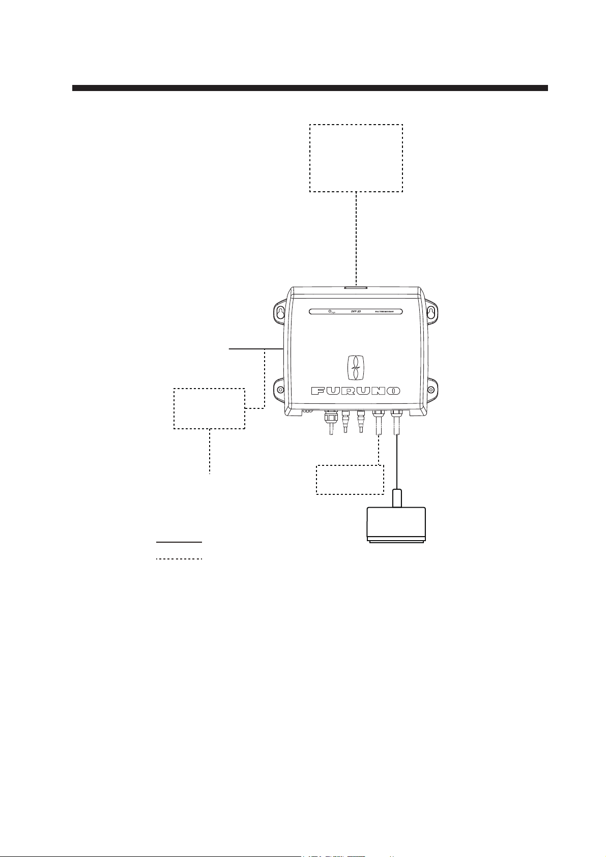
SYSTEM CONFIGURATION
NavNet TZtouch
TZT9/14/BB
NavNet TZtouch2
TZTL12F/15F
MULTI BEAM SONAR
DFF-3D
12-24 VDC
Rectifier
PR-62
100/110/220/230 VAC
1ø, 50/60 Hz
: Standard supply
: Optional or local supply
External
KP
Transducer
B54 or TM54
vii
Page 10

SYSTEM CONFIGURATION
This page is intentionally left blank.
viii
Page 11

1. INSTALLATION
1.1 Equipment Lists
Standard supply
Name Type Code No. Qty Remarks
Multi Beam Sonar DFF-3D - 1
Transducer B54 - 1 Select one.
TM54 -
Spare Parts SP02-05601 001-033-740 1 set Fuses
Installation Materials CP02-09400 000-029-992 1 set • Power cable assy. (3.5 m)
Optional supply
B54: Thru-hull mount
TM54: Transom mount
• LAN cable assy. (5 m)
• Self-tapping screws
• Conductive tape
Name Type Code No. Remarks
Connector Kit for TX Sync OP02-86 001-205-780
Cable Assembly MOD-Z072-020+ 001-167-880-10 2 m, for HUB-101
Cable Assembly MOD-Z072-100+ 001-167-900-10 10 m, for HUB-101
Rectifier PR-62 000-013-484 100 VAC
000-013-485 110 VAC
000-013-486 220 VAC
000-013-487 230 VAC
1-1
Page 12

1. INSTALLATION
1.2 How to Install the Sonar
This sonar can be installed on a deck or on a bulkhead. When selecting a mounting
location, keep the following points in mind:
• Install the unit indoors.
• The operating temperature range of this unit is -15°C to 55°C (-27°F to 99°F). Be
sure the mounting location satisfies this requirement.
• Locate the unit away from exhaust pipes and vents.
• The mounting location should be well ventilated.
• Mount the unit where shock and vibration are minimal.
• Keep the unit away from electromagnetic field-generating equipment such as motors and generators.
• Observe the minimum recommended maintenance space shown in the outline
drawing at the back of this manual. Also, leave slack in cables for maintenance and
servicing ease.
• A magnetic compass may receive interference if it is placed too close to this unit.
Observe the compass safe distances noted in the safety instructions to prevent interference to the magnetic compass.
• For mounting on a bulkhead, the connectors must face downward.
Fasten the unit to the mounting location with four self-tapping screws (5×20, supplied),
referring to the outline drawing at the back of this manual for mounting dimensions.
1-2
Page 13
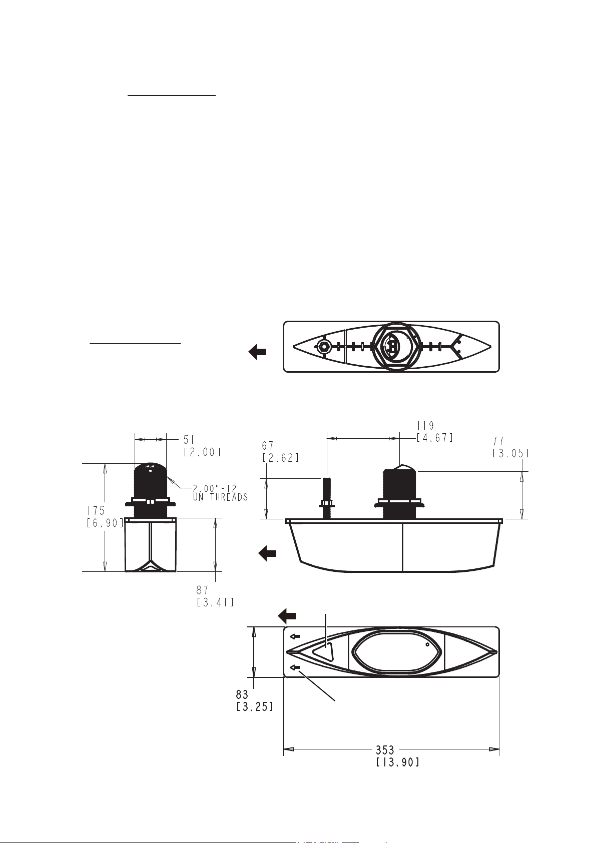
1.3 Transducer
Thru-hull mount
The installation position of the transducer directly affects the performance of the transducer. For best performance, keep the following points in mind when selecting the
mounting location.
• Select a location where the influence of water flow and air bubbles is minimal.
• Select a place least influenced by engine noise.
• Do not install the transducer inboard.
• For FRP vessel, do not cover the transducer with fiberglass, to prevent damage to
the transducer if the temperature rises.
• Bottom slope angle less than 24°
The illustration below is the transducer with fairing, and was created by the Airmar
Technology Corporation. The BOW mark (arrow) on the fairing and the triangular recess should be facing the bow.
1. INSTALLATION
®
Unit of measurement
Top: millimeter
Bottom: inch
BOW
BOW
BOW
Triangular recess
BOW mark
1-3
Page 14
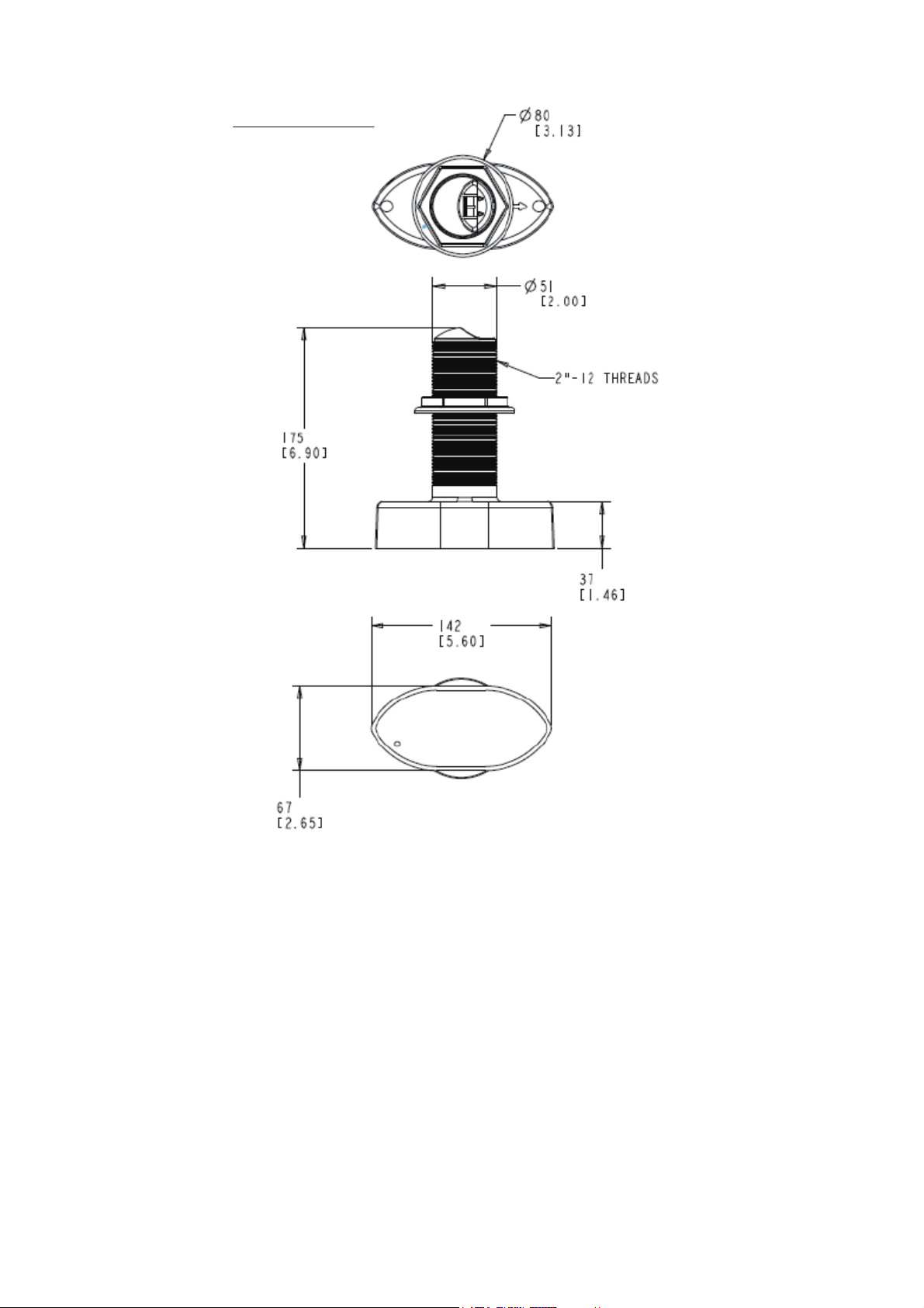
1. INSTALLATION
Unit of measurement
Top: millimeter
Bottom: inch
1-4
Page 15
1. INSTALLATION
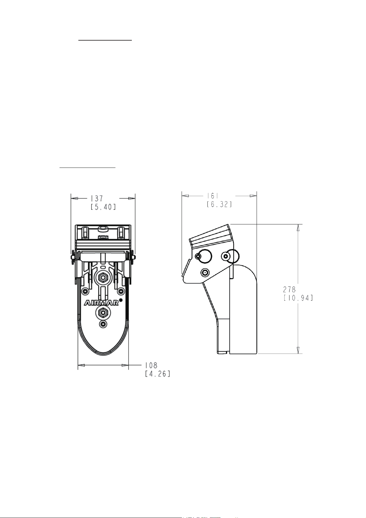
Transom mount
For a vessel with an inboard engine, the transducer cannot be installed aft of the propeller screw because of the turbulence created by the propeller ahead of the transducer. Determine the mounting location considering the guidelines shown below and the
instructions on page AP-8.
• Select a location as far as possible from the propeller screw.
• Select a location where the propeller screw is not within 120° of the beam range of
the transducer.
Be sure to select the location considering these guidelines, to prevent echo noise on
the display.
The illustration below was created by the Airmar
Unit of measurement
Top: millimeter
Bottom: inch
®
Technology Corporation.
1-5
Page 16

1. INSTALLATION
This page is intentionally left blank.
1-6
Page 17

2. WIRING
Connect the power cable and transducer cable as shown below. See the next page
for how to fabricate the transducer cable.
TZT9/TZT14/TZTBB
TZTL12F/TZTL15F
MOD-Z072-050+, 5 m
(option: 2/10 m)
1.4-0.7A
Ground wire
(IV-2 sq)
GROUND
2.1 Ground
Connect a ground wire (IV-2 sq, local supply) between the ground terminal and ship’s
ground to prevent interference to the sounder picture. Make the length of the wire as
short as possible. For FRP vessels, install a ground plate (approx. 20 cm by 30 cm)
on the outside of the hull bottom and connect the ground wire there.
MJ-A3SPF0013-035C
(3.5 m)
External
KP
Power supply
(12-24 VDC)
Transducer
B54 or TM54
2-1
Page 18
2. WIRING
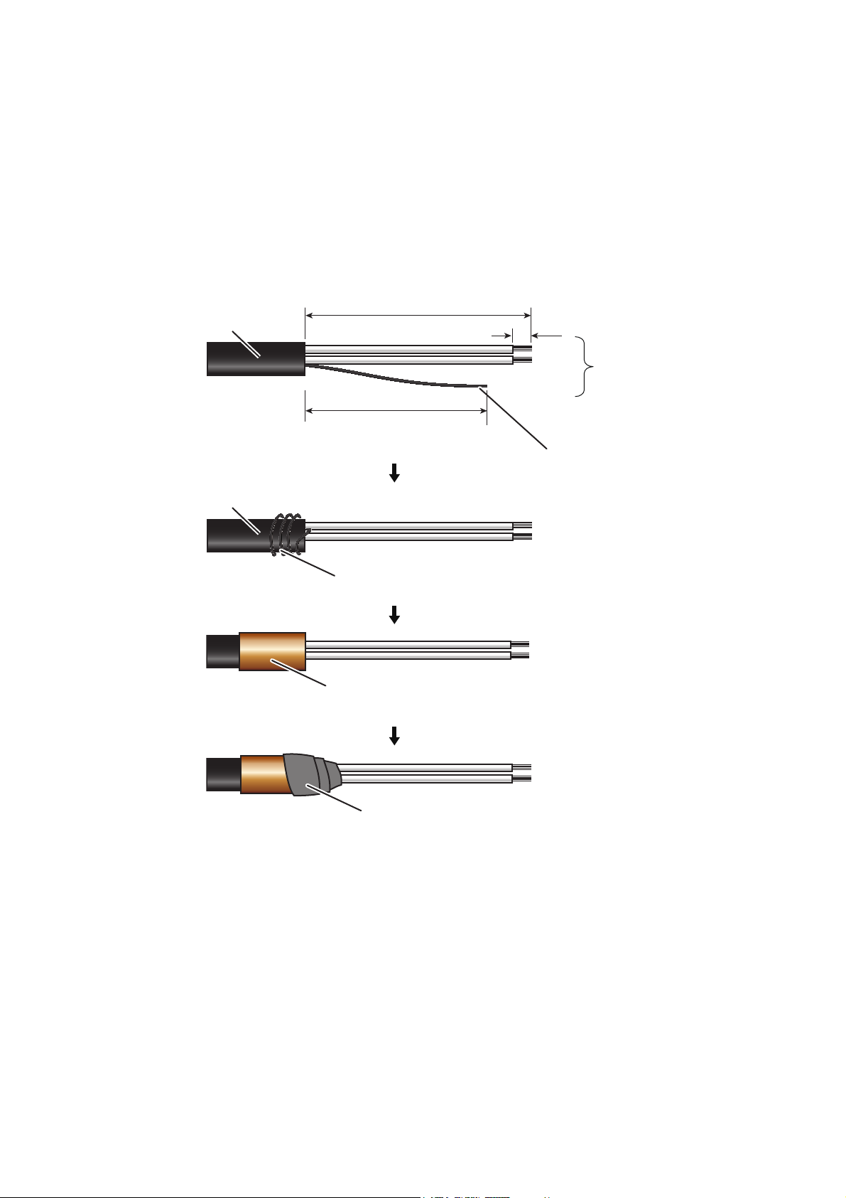
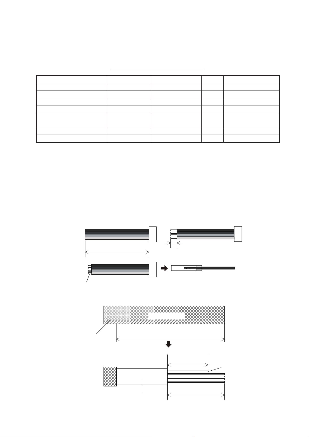
Unit: mm
Sheath
x9x9
ShieldShield
110
6
80
Wrap with vinyl tape (width: 30 mm).
Sheath
2.2 Transducer Cable
Separate the transducer cable as far as possible from power cables to prevent interference to the sonar. Keep the transducer cable away from televisions and monitors
to prevent noise in the cable.
Fabricate the cable as shown in the procedure below, then connect it inside the unit
with a WAGO connector.
1. Fabricate the cable as shown below.
Note: Keep the recommended lengths to prevent noise in the cable.
Wrap shield around sheath.
Wrap shield with conductive tape.
2. Remove the outer cover.
3. Unfasten four screws to remove the inner chassis cover.
2-2
Page 19
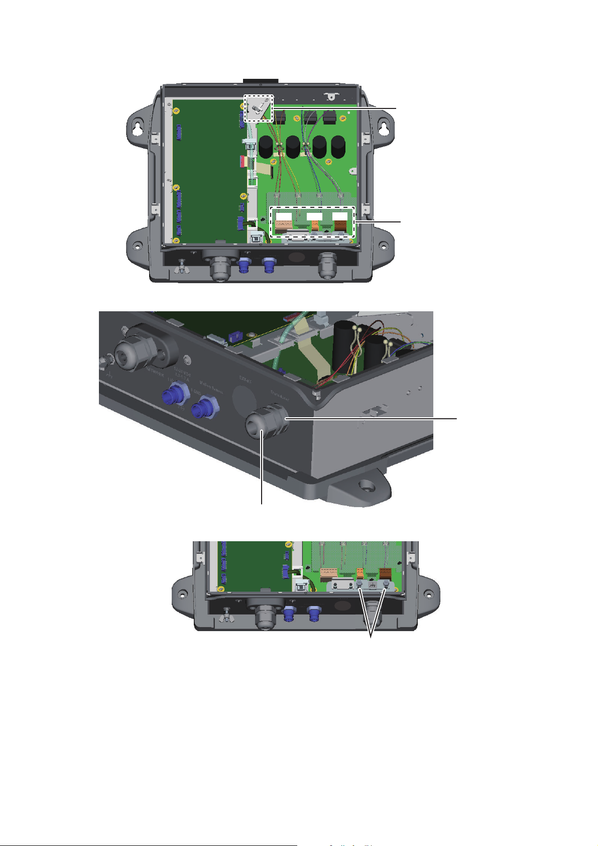
4. Detach three WAGO connectors, TB1, TB2, TB3.
WAGO connector
opener
WAGO connector
Super gland
Sealing nut
TB1TB2TB3
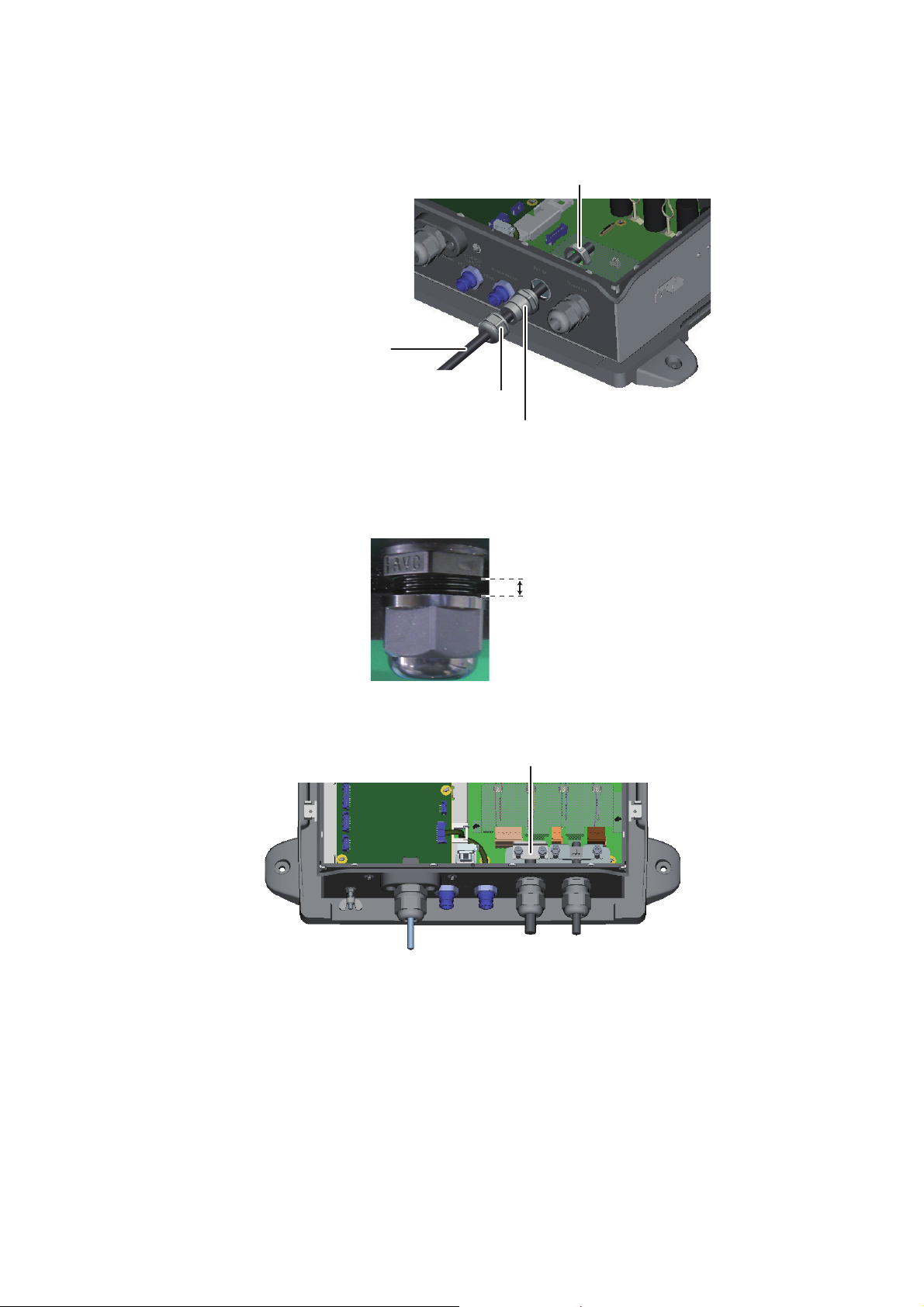
5. Unfasten the sealing nut from the super gland for the transducer cable.
2. WIRING
6. Unfasten two screws to remove the clamping plate for the transducer cable.
Unfasten these screws to
remove the clamping plate.
7. Pass the transducer cable through the sealing nut (unfastened at step 5), then
pass the cable through the super gland and into the unit.
2-3
Page 20
2. WIRING
How to connect cable to WAGO connector
Push down
Opener
WAGO
connector
8. Referring to the interconnection diagram (at the back of this manual) and the illustration below, connect the transducer cable to WAGO connectors. (The WAGO
connector opener is provided inside the unit. See the figure at step 4 for the location.)
<Procedure>
1. Twist core.
2. Insert opener in hole and
push down.
Wire
Twist
3. Insert core into hole.
4. Release opener.
5. Tug on wire to confirm tight
connection.
9. Reattach the WAGO connectors.
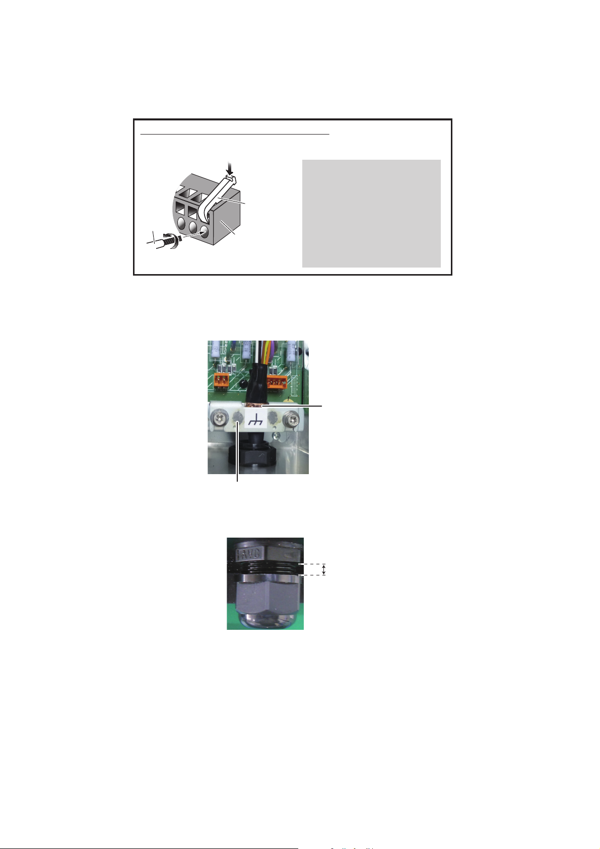
10. Set the cable where the clamping plate was removed (at step 6). As shown in the
figure below, lay the cable such that its conductive tape lies beneath the clamping
plate. Hold the clamping plate in place with your fingers then fasten the plate.
Conductive
tape
Clamping plate
11. Fasten the sealing nut into the super gland. The gap between the sealing nut end
and the super gland should be 2 mm. The fastening torque is 1.8 - 2.0 N•m.
2 mm
12. Reattach the inner and outer covers.
2-4
Page 21
2. WIRING
(b)
Approx. 10 mm
(a)
Approx. 100 mm
(c)
Fold back core.
A
2.3 External KP Cable
The Connector Kit for TX Sync (see the table below) and the cable MPYC(SLA)-4 are
required to connect external KP.
Contents of Connector kit for TX sync
Name Type Code No. Qty Remarks
Upset UI Screw-B M4u20 000-163-756-10 2
Super Gland MGB20M-12B 000-177-248-10 1
PH Connector Assembly 02-1097 (4P) 001-206-000 1
Cable Clamping Plate 02-167-1528 100-379-090-10 1
Rainproof Panel 02-167-1529 100-379-100-10 1 No use. May be
discarded.
EMI Core GRFC-10 000-177-010-10 1
Crimp-on Lug NCW-1.25 000-157-213-10 4
Note: FURUNO recommends use of the JIS cable MPYC(SLA)-4 (or equivalent, see
Appendix 1). However, if the wiring environment is such that the cable may contact
seawater, use a cable whose armor is covered with a vinyl sheath to prevent corrosion.
1. Fabricate the cable for the external KP as shown below.
a) Make the length of the wires of the PH connector assembly (supplied) 100 mm.
b) Remove the sheath from the cores 10 mm.
c) Fold back the cores in half. Attach crimp-on lug NCW-1.25 (supplied) to each
core.
d) Remove the armor 300 mm and cut off the vinyl sheath 130 mm
MPYC(SLA)-4
rmor
Vinyl sheath
300 mm
80 mm
Shield
130 mm
2-5
Page 22
2. WIRING
This part is fixed with
the sealing nut.
Lay this part in
the cable clamp.
Armor
Vinyl sheath
NCW-1.25
Wrap with
vinyl tape.
Wrap with
vinyl tape.
Crimp-on lug
FV1.25-4(LF) RED
Protective sheet
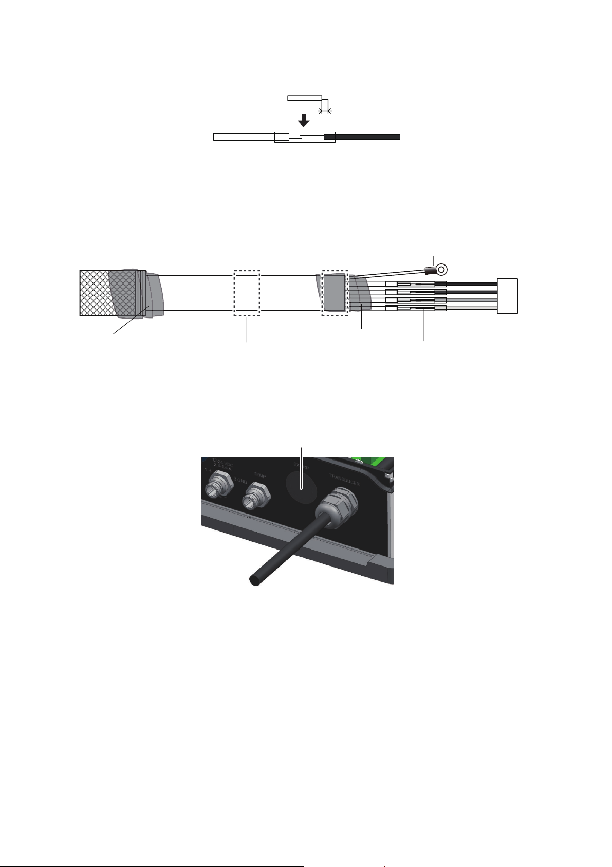
e) Remove 5 mm of the vinyl sheath from the cores then connect a crimp-on lug
to each core as shown below.
Approx. 5 mm
f) Attach supplied crimp-on lug (FV1.25-4(LF) RED)) to the shield.
g) Referring to the illustration below, wrap the armor with vinyl tape at the loca-
tions shown. Pass the cable through its cable gland. Fix the cable with the cable clamp and sealing nut.
2. Remove the outer cover.
3. Loosen four screws to remove the inner chassis cover.
4. Detach the protective sheet from the location for the external KP cable.
2-6
Page 23
2. WIRING
Secure cable with cable clamping plate.
5. Unfasten the sealing nut and lock nut from the supplied super gland. As shown
below, pass the cable through the sealing nut, super gland, hole in the unit and
the lock nut.
Lock nut
Cable for external KP
(MPYC(SLA)-4)
Sealing nut
Super gland
6. Fasten the lock nut to fix the super gland to the unit.
7. Fasten the sealing nut into the super gland. The gap between the sealing nut end
and the super gland should be 4 mm. The fastening torque is 1.8 - 2.0 N m.
4 mm
8. Position the cable so its vinyl sheath lies in the cable clamp. Use the supplied cable clamping plate to secure the cable.
2-7
Page 24

2. WIRING
Cable saddle
EMI core
10 mm
Super gland
J9
9. Connect the KP cable. Pass the PH connector through the clamp shown below,
then connect it to J9 on th DIGI board. Make sure the cable does not contact the
WAGO connector (TB3). Also, secure the shield of the external KP cable to the
plate where the transducer cable is fixed.
Make sure cable does
not contact TB3.
Shield
Clamp
Lay vinyl sheath in the cable clamp and
secure the cable with the cable clamp.
Note 1: As shown in the figure below, pass the cable through the cable saddle.
Make sure the crimp connectors are not clamped by the cable saddle.
Note 2: Confirm that the direction of the clamping plate is as shown below.
Clamping
plate
Crimp connectors
10. Attach the supplied EMI core (GRFC-10) to the cable for the external KP, approx.
10 mm from the super gland.
2-8
10 mm
11. Reattach the inner and outer covers.
Super gland
EMI core
Page 25

2.4 LAN Cable
How to detach clamping claw
Hold the clamping
claw/seal assy. as shown
left, with the teeth of
the clamping claw toward
you.
Push in the sealing insert
with your thumbs.
Sealing nut
Seal assy.Seal assy.
Clamping
claw
Sealing
insert
Super
gland
Sealing nut
LAN cable
Sealing insert
(Push cable into slit.)
Clamping claw
Do as follows to connect the supplied LAN cable (MOD-Z072-050+) or the optional
LAN cable (MOD-Z072-020+, MOD-Z072-100+).
1. Unfasten the sealing nut from the LAN connector then remove the sealing insert
and clamping claw.
2. Detach the sealing insert from the clamping claw as shown below.
2. WIRING
3. Pass the sealing nut, clamping claw and sealing insert onto the LAN cable in the
order shown in the figure below. Connect the cable to the LAN connector. (Note
the orientation of the sealing insert when passing it onto the cable. Push the cable
into the slit in the sealing insert.)
4. Set the sealing insert and clamping claw into the sealing nut then tighten the nut.
2-9
Page 26

2. WIRING
5. Fasten the sealing nut to fasten the LAN cable. The clearance between the sealing nut and the super gland shall be 3 mm. The fastening torque for the sealing
nut is 1.8 - 2.0 Nm.
3 mm
How to disconnect the LAN cable
Loosen the two screws on the gland to access the cable’s connector. A lock washer
is fitted to the gland, so the screws cannot be unfastened completely.
Gland
Screw (2 pcs.)
2-10
Page 27

3. INITIAL SETTINGS
WARNING
Do not open the equipment unless totally
familiar with electrical circuits.
Only qualified personnel are permitted to
work inside the equipment.
3.1 DIP Switch Setting
The DIP switches S2 and S3 should be left in the default position (OFF).
S2S3
DIP switch S2
12345678
OFF
DIP switch S3
1234
OFF
3-1
Page 28

3. INITIAL SETTINGS
DIP switch S2 setting options (reference only)
Switch
No.
1 Automatic IP address assignment OFF: Fixed (static) IP address. Set the IP address
2 IP address no. Effective when #1 segment is OFF. (See the table
3 Restore default settings (other than
LAN)
4 Restore ALL default settings See section 5.3.
5 - 6 Keep these switches in the OFF position.
7 No use.
8 No use.
#2 Host name IP address
OFF ES092021 172.031.092.021
ON ES092022 172.031.092.022
Function Setting
with switch #2.
ON: IP address assigned automatically.
below for IP address. Currently, this function has no
use.)
See section 5.3.
After setting up the transducer for the DFF3D, set the transducer type at the NavNet
device (NavNet TZtouch/NavNet TZtouch2). See respective Installation Manual for
the procedure.
3-2
Page 29

3.2 Operation Check
After connecting the NavNet TZtouch/NavNet TZtouch2, power the unit on/off from the
ship’s switchboard. The LED on the cover of the DFF-3D lights or flashes according
to equipment state, as described in the table below.
LED state Meaning
Lit continuously Standby state. (If no signal is received via LAN for more
Blinking every two seconds Normal operation
㻸㻱㻰
3. INITIAL SETTINGS
LED state and meaning
than 10 minutes, the equipment automatically goes into
standby to lessen power consumption.)
3-3
Page 30

3. INITIAL SETTINGS
3.3 Multi Function Display Initial Settings
How to open the menu
NavNet TZtouch:
1. Push the Home button (or tap the home icon) to display the menu icon bar.
2. Select [Menu], [Multibeam Sonar].
3. Enter initial settings referring to the table below.
NavNet TZtouch2:
1. Tap the Home icon to go to the home screen.
2. Select [Settings], [Multibeam Sonar].
3. Enter initial settings referring to the tables that follow.
Multibeam Sonar menu
Menu item Description Options (setting range)
[Transducer Draft] Set the distance between the transducer
and the draft line to show the distance
from the sea surface.
[Salt Water] Select [ON] to use this equipment in salt
water.
[Transducer Setup] Set page 3-6 “Transducer Setup”.
[Transmission Power Au-
to]
[Transmission Power]
[External KP] Select [ON] to synchronize with external
[Bottom Level] The default bottom level setting (0) de-
[Auto Gain Offset (Multi
Sounder)],
[Auto Gain Offset (Side
Scan)],
[Auto Gain Offset (Cross
Section)]
Turn on to automatically adjust trans-
mission power to display the seabed
echo properly.
Set the TX power level manually. Inter-
ference may appear on your display
when a sonar of the same frequency as
yours is being operated on a vessel
nearby. When this occurs, lower the
transmission power and request the
nearby vessel to lower its sonar’s TX
power to reduce the interference. The
setting range is 0 to 10 and 10 is maxi-
mum power.
sounder’s keying pulse.
termines that two strong echoes re-
ceived in sequence are seabed echoes.
If the depth indication is not stable in the
default setting, adjust the bottom level
here. If you can not discriminate the fish
near the seabed from the seabed echo,
increase the bottom level.
In the auto mode, lower or raise the gain
as necessary.
[0.0m] to [99.9m]
[OFF], [ON]
[OFF], [ON]
[0] to [10]
[ON], [OFF]
[-40] to [40]
[-5] to [5]
3-4
Page 31

3. INITIAL SETTINGS
Menu item Description Options (setting range)
[STC (Side Scan)],
[STC (Multi Sounder)]
[TX Pulse] The pulse length is automatically set ac-
[DFF-3D Monitoring] Display pitch and roll (measured by internal sensor) and B voltage.
[Set Hardware to Factory
Default]
[Restore Default Settings] Restore all menu settings to default. [OK], [Cancel]
STC reduces surface layer noise, to discriminate surface fish from surface layer
noise. [0] is OFF and [10] reduces noise
approx. 5 m from the transducer. Too
high a setting may erase wanted fish
echoes.
cording to range. Use a short pulse for
better resolution and a long pulse when
detection range is important. To improve
resolution on the side scan display, etc.,
use [Short 1] or [Short 2].
• [Short 1] improves the detection resolution, but the detection range is
shorter than with [Std] (pulse length is
1/4 of [Std]).
• [Short 2] raises the detection resolution, however detection range is
shorter (pulse length is about 1/2 of
[Std]) than [Std].
• [Std] is the standard pulse length, and
is suitable for general use.
• [Long] increases the detection range
but lowers the resolution (about 1/2
compared to the [Std] pulse length)
Reset the external fish finder to its factory default settings.
[0] to [10]
[Short1], [Short2],
[Standard], [Long]
[OK], [Cancel]
3-5
Page 32

3. INITIAL SETTINGS
GCTD
GC
TD
Up dir.: "+"
Stern dir.: “+”
Port dir.: "+"
Top view
Starboard view
GC: Gravity Center, TD: Transducer
Transducer Setup menu
For the oscillation center see “Motion Sensor menu” on the next page.
If the center of gravity is not known, see the drawing below.
W/2
Engine
W
L/3
H
Engine
GC: Gravity Center
GC
L
GC
H/2
Note: The location of the center of gravity may be different than as shown in the figures above, depending on hull shape, engine position and the installation status of
other equipment.
Menu item Description
[Transducer Mis-
Set to [ON] if the transducer is installed facing the stern. [ON], [OFF]
mount Correction]
[Transducer Position
Bow/Stern]
Set the distance from the transducer to the ship’s center
of gravity in the bow/stern direction. For stern location,
set a positive value.
[Transducer Position
Up/Down]
Set the distance from the transducer to the ship’s center
of gravity in the up/down (vertical) direction. For upward
location, set a positive value.
[Transducer Position
Port/Starboard]
Set the distance from the transducer to the ship’s center
of gravity in the port/starboard direction. For port location,
set a positive value.
Top view
Starboard view
Options
(setting range)
-100.0 to 100.0
(m)
-100.0 to 100.0
(m)
-100.0 to 100.0
(m)
3-6
Page 33

3. INITIAL SETTINGS
GC
GC
W
W/2
Top view
Starboard view
Engine
H
H/2
L/3
L
GC: Gravity Center
GC: Gravity Center, TD: Transducer
Engine
Motion Sensor menu
Select [Transducer Setup] on the [Multibeam Sonar] menu to show the [Motion Sensor] menu (below the [Transducer Setup] menu).
Port dir.: "+"
SC
GCTD
Stern dir.: "+"
SC
Up dir.: "+"
GC
TD
GC: Gravity Center, TD: Transducer,
Top view
Starboard view
SC: Satellite Compass
If the center of gravity is not known, see the drawing below.
Note: The location of the center of gravity may be different than as shown in the figures above, depending on hull shape, engine position and the installation status of
other equipment.
Menu item Description
[Motion Sensor
Source]
[Motion Sensor
Pos. Bow/Stern]
Options
(setting range)
Select the sensor connected to you NavNet TZtouch2 unit. [SC], [Internal],
[OFF]
Set the distance from the transducer to the motion sensor
-100 to 100.0 (m)
in the bow-stern direction. For the stern side, set a positive
value.
Note: This menu appears if the motion sensor source is
selected to [SC].
3-7
Page 34

3. INITIAL SETTINGS
Heading sensor time lag: 20 msec
DFF-3D
SC-30
-----------------Ethernet
CAN bus
------------
Motion sensor time lag: 20 msec
Position sensor time lag: 20 msec
Multi Function
Display
Menu item Description
[Motion Sensor
Pos. Up/Down]
[Motion Sensor
Pos. Port/Starboard]
[GPS Sensor
Pos. Bow/Stern]
[GPS Sensor
Pos. Up/Down]
[GPS Sensor
Pos. Port/Starboard]
[Roll Sensor Offset]
Set the distance from the transducer to the motion sensor
in the up/down (vertical) direction. Use a "+" value for upward direction.
Note: This menu appears if the motion sensor source is
selected to [SC].
Set the distance from the transducer to the motion sensor
in the port-starboard direction. For port location, set a positive value.
Note: This menu appears if the motion sensor source is
selected to [SC].
Set the distance from the transducer to the GPS sensor in
the bow-stern direction. For stern location, set a positive
value.
Set the distance from the transducer to the GPS sensor in
the up/down (vertical) direction. Use a "+" value for upward
direction.
Set the distance from the transducer to the GPS sensor in
the port-starboard direction. For port location, set a positive value.
Set the roll offset to use with the internal motion sensor.
Note: This menu appears if the motion sensor source is
selected to [Internal].
Options
(setting range)
-100 to 100.0 (m)
-100 to 100.0 (m)
-100 to 100.0 (m)
-100 to 100.0 (m)
-100 to 100.0 (m)
-45.0 to 45.0
[Pitch Sensor
Offset]
[Motion Sensor
Time Lag (in ms)]
[Heading Sensor
Time Lag (in ms)]
[Position Sensor
Time Lag (in ms)]
Sync (time lag) setting
• If the equipment is connected as shown below, no adjustment to the time lag settings is necessary.
Set the pitch offset to use with the internal motion sensor.
Note: This menu appears if the motion sensor source is
selected to [Internal].
Set the time lag to use with the external motion sensor.
Note: This menu appears if the motion sensor source is
selected to [SC].
Set the time lag for the data received from the position sensor.
Set the time lag for the data received from the position sensor.
-45.0 to 45.0
0 to 400
0 to 3500
0 to 3500
3-8
Page 35

3. INITIAL SETTINGS
Heading sensor time lag: 65 msec
DFF-3D
PG-700 (Motion data and heading data)
-----------------Ethernet CAN bus
------------------
Motion sensor time lag: 65 msec
Position sensor time lag: 65 msec
-----------
㻂
㻂
GP-330B (Position data)
Multi Function
Display
• If the equipment is connected as shown in the figure below, change the time lag settings as indicated.
• If the connection is different from those mentioned here, calculate the time lag for
each sensor and enter them accordingly, using the following formula.
Time lag = Transmission delay + Propagation delay
Transmission delay: Delay required for calculation and output by the motion sensor, heading sensor, and position sensor.
SC-30: Use 5 msec for the calculation.
PG-700: Use 50 msec for the calculation.
GP-330B: Use 50 msec for the calculation.
Propagation delay: Time required for the data to reach the DFF-3D, via repeater
and data route. For the multi function display connected by CAN bus, use 15 msec
for the calculation. If NMEA data is fed to the DFF-3D via the NMEA Data Converter
(IF-NMEA2K2), set the calculation figure according to the baud rate between the
sensor and the IF-NMEA2K2 as shown below.
38400 bps: Use 40 msec for the calculation.
4800 bps: Use 145 msec for the calculation.
For example, the sensor feeding data to the multi function display via the IFNMEA2K2 has a transmission delay of 30 msec and a baud rate of 38400 bps.
Then, the time lag would be as shown in the calculation below.
Time lag 70 msec = Transmission delay 30 msec + Propagation delay 40 msec
3-9
Page 36

3. INITIAL SETTINGS
This page is intentionally left blank.
3-10
Page 37

4. OPERATION
A-scope
Frequency
Depth scaleDepth scale
19.5
Below transducerBelow transducer
Seabed
echo
Max. display depthMax. display depth
Depth
This chapter describes the display and operations for the Multi Beam Sonar. For basic
operations with the NavNet TZtouch multi function display, such as touch operations
and power on/off, see the Operator’s Manual for the NavNet TZtouch.
The DFF-3D has four display screens (modes), multi sounder, side scan, cross section, and 3D sounder history.
4.1 Display Screens Overview
Multi-sounder display
Tap the multi-sounder display icon on the home screen to show the multi-sounder display.
The multi-sounder display operates similar to the conventional fish finder, providing information about the seabed and underwater conditions. The video display scrolls from
the right to left with the passing of time.
The echoes appearing at the right edge of the display are the latest echoes. Echoes
from individual fish, schools of fish and the seabed are shown. With the gain set properly, the distance to the seabed appears on the screen.
The gain, clutter suppressor and TVG are adjusted according to the mode selected,
auto fishing or auto cruising. Manual adjustment of those controls is also possible.
The single beam presentation displays the information detected by the downwardlooking beam. The triple beam presentation displays the information detected by the
port beam, starboard beam, and downward-looking beam.
Single beam display
4-1
Page 38

4. OPERATION
19.5
Depth
scale
Depth
scale
Seabed
echo
Frequency
Depth
PortPort StarboardStarboardDownwardDownward
Max. display depthMax. display depth
Fish bed
Fish bed
Frequency
Max. display depth
Underwater
Underwater
Seabed
Seabed
Side scan display
Tap the side scan display icon on the home screen to show the side scan display.
Triple beam display
The side scan display shows the echoes received from the port and starboard directions.
The side scan display starts from the center of the vessel, and traces in the port and
starboard directions. The most recent echoes are at the top of the screen and the oldest are at the bottom of the screen.
The side scan display is different from the other modes employed by this equipment it clearly displays the shape of echoes (fish bed, etc.).
Depth scale
Seabed
Fish bed
Depth
Underwater
Max. display depth
Frequency
Underwater
Seabed
Fish bed
4-2
Port direction echoes Starboard direction echoes
Page 39

4. OPERATION
Horizontal range scaleHorizontal range scale
SeabedSeabed
FrequencyFrequency
GridGrid
Depth
Depth
scale
Depth
scale
Max. display depthMax. display depth
Transducer
position
Transducer
position
UnderwaterUnderwater
DownwardDownwardPortPort StarboardStarboard
Horizontal range scale
Frequency
Own ship
Max. display depth
Depth scale
School of fish
Seabed
Cross section display
㻻㼣㼚㻿㼔㼕㼜㻻㼣㼚㻿㼔㼕㼜
STBDPORT
Tap the cross section display icon
on the home screen to show the
cross section display.
The cross section display, shows
seabed and underwater conditions.
Seabed
School of
fish
This multi beam sonar uses a 120°
beam (downward to port 60°; downward to starboard 60°), providing highly accurate
underwater images.
3D sounder history display
Tap the 3D sounder history display icon on the home screen to show the D sounder
history display.
The 3D sounder history provides a 3D graphic of the past seabed and underwater
echoes detected by your vessel. The display can be used to detect schools of fish.
Horizontal range scale
Depth/Color Shading
color scale
Depth
Depth scale
School of fish
Frequency
Own ship
Seabed
Max. display depth
4-3
Page 40

4. OPERATION
4.2 Multi-Sounder Display Operations
This section covers the functions available with the multi-sounder display. For the
menu items shared with the conventional fish finder, see the applicable Operator’s
Manual.
4.2.1 How to switch between TX and STBY
Tap the multi-sounder display to show the pop-up menu. Select [TX] to start transmitting. [ST-BY] appears at the center of the screen when transmission is stopped.
4.2.2 How to switch between single beam and triple beam presentations
1. Tap the multi-sounder display to show the pop-up menu.
2. Select [Mode].
3. Select [Single Beam] or [Triple Beam] as required.
4. Select [Close] to close the pop-up menu.
4.2.3 How to set the TX beam angle
You can set the TX beam angle for the port, starboard and downward beams.
1. Tap the multi-sounder display to show the pop-up menu.
2. Select [Beam Angle].
3. Set the beam angle as required.
4.2.4 How to set the TX beam width
You can set the TX beam width for the port, starboard and downward beams.
1. Tap the multi-sounder display to show the pop-up menu.
2. Select [Beam Width].
3. Set the beam width as required.
4.2.5 How to show or hide the scale box
The scale box, shown at the bottom left corner on the display, shows depth, current
range, and TX frequency. You can show the box as follows.
1. Tap the multi-sounder display to show the pop-up menu.
4-4
2. Select [Scale Box] to show the scale box.
Page 41

4. OPERATION
Port
Starboard
Downward
4.2.6 Availability of points and event marks registration, and go to a point
For how to register points and event marks, see the NavNet TZtouch or NavNet TZtouch2 manual.
The table below shows function availability according to latitude/longitude, heading
data presence or absence. If there is no latitude/longitude data, none of the functions
below are available.
For NavNet TZtouch or NavNet TZtouch2, input PGN data. The PGN data available is
as shown below.
Latitude/longitude data
• 129025 Position, Rapid Update
• 129029 GNNS Position Data
Heading data
• 127237 Heading/Track Control
• 127250 Vessel Heading
• 130577 Direction Data
Latitude/Longitude / Heading data: YES
Item Starboard Downward Port
Point registration Yes Yes Yes
Go to point Yes Yes Yes
Event mark registration Yes Yes Yes
Latitude/Longitude: YES, Heading data: NO
Item Starboard Downward Port
Point registration No Yes No
Go to point No Yes No
Event mark registration Yes Yes Yes
Port
Downward
Starboard
4-5
Page 42

4. OPERATION
4.3 Side Scan Display Operations
This section covers the functions available with the side scan display. For the menu
items shared with the conventional fish finder, see the applicable Operator’s Manual.
4.3.1 How to switch between TX and STBY
Tap the side scan display to show the pop-up menu. Select [TX] to start transmitting.
[ST-BY] appears at the center of the screen when transmission is stopped.
4.3.2 How to change echo color
1. Select [Menu] from the menu icon bar to show the menu.
2. Select [Multibeam Sonar].
3. Select [Echo Color].
4. Select [White], [Blue] or [Brown] as required.
5. Select [Close] to close the pop-up menu.
4.3.3 How to show or hide the scale box
The scale box, shown at the bottom left corner on the display, shows depth, current
range, and TX frequency. You can show the box as follows.
1. Tap the side scan display to show the pop-up menu.
2. Select [Scale Box] to show the scale box.
4-6
Page 43

4. OPERATION
4.3.4 Availability of points and event marks registration, and go to a point
For how to register points and event marks, see the NavNet TZtouch or NavNet TZtouch2 manual.
The table below shows function availability according to latitude/longitude, heading
data presence or absence. If there is no latitude/longitude data, none of the functions
below are available.
For NavNet TZtouch or NavNet TZtouch2, input PGN data. The PGN data available is
as shown below.
Latitude/longitude data
• 129025 Position, Rapid Update
• 129029 GNNS Position Data
Heading data
• 127237 Heading/Track Control
• 127250 Vessel Heading
• 130577 Direction Data
Latitude/Longitude / Heading data: YES
Item Starboard Port
Point registration Yes Yes
Go to point Yes Yes
Event mark registration Yes Yes
Latitude/Longitude: YES, Heading data: NO
Item Starboard Port
Point registration No No
Go to point No No
Event mark registration Yes Yes
4-7
Page 44

4. OPERATION
4.4 Cross Section Display Operations
This section covers the functions available with the cross section display. For the
menu items shared with the conventional fish finder, see the applicable Operator’s
Manual.
4.4.1 How to switch between TX and STBY
Tap the cross section display to show the pop-up menu. Select [TX] to start transmitting. [ST-BY] appears at the center of the screen when transmission is stopped.
4.4.2 How to show or hide the grid
The grid, which is useful for measuring the distance to a target, can be shown or hidden as follows.
1. Tap the cross section display to show the pop-up menu.
2. Select [Grid] to show the grid.
4.4.3 Zoom display
The seabed echo can be zoomed.
1. Tap the cross section display to show the pop-up menu.
2. Select [Zoom] to zoom the seabed echo. Select [Zoom] again to restore the normal display.
Zoomed display Normal display
4.4.4 How to smooth echoes (distance)
If echoes are “disconnected” because of an undulating seabed, change the setting to
[Low], [Medium] or [High] as necessary. Smoothing is done in the range direction to
smooth the echo presentation.
4-8
1. Select [Menu] from the menu icon bar to show the menu.
2. Select [Multibeam Sonar].
3. Select [Echo Smoothing (Distance)].
4. Select [Low], [Medium] or [High] as required. The default setting is [Medium]. Select [OFF] to stop smoothing.
5. Select [Close] to close the pop-up menu.
Page 45

4.4.5 How to smooth echoes (time)
If echoes are difficult to see because they appear “speckled,” use the echo smoothing
feature to suppress the speckling by time.
1. Select [Menu] from the menu icon bar to show the menu.
2. Select [Multibeam Sonar].
3. Select [Echo Smoothing (Time)].
4. Select [Low], [Medium] or [High] as required. The default setting is [Medium]. Select [OFF] to stop smoothing.
5. Select [Close] to close the pop-up menu.
4.4.6 How to apply correction to the speed of sound
Even though the sea bottom is flat, the left or right edge, up or down may be distorted.
To compensate for this problem, adjust the speed of sound.
Manual correction
1. Select [Menu] from the menu icon to show the menu.
4. OPERATION
2. Select [Multibeam Sonar].
3. Select [Sound Speed Correction], then enter a correction. The setting range is
-200 to +200.
4. Select [Close] to close the menu.
Automatic correction
1. Select [Menu] from the menu icon to show the menu.
2. Select [Multibeam Sonar].
3. Select [Temp.-based Correction], then select [ON].
Select [OFF] to remove the correction.
4. Select [Close] to close the menu.
4.4.7 How to show or hide the scale box
The scale box, shown at the bottom-left corner on the display, shows depth, current
range, and TX frequency. You can show the box as follows.
1. Tap the cross section display to show the pop-up menu.
2. Select [Scale Box] to show the scale box.
4-9
Page 46

4. OPERATION
4.4.8 Availability of points and event marks registration, and go to a point
For how to register points and event marks, see the NavNet TZtouch or NavNet TZtouch2 manual.
The table below shows function availability according to latitude/longitude, heading
data presence or absence. If there is no latitude/longitude data, none of the functions
below are available.
For NavNet TZtouch or NavNet TZtouch2, input PGN data. The PGN data available is
as shown below.
Latitude/longitude data
• 129025 Position, Rapid Update
• 129029 GNNS Position Data
Heading data
• 127237 Heading/Track Control
• 127250 Vessel Heading
• 130577 Direction Data
Latitude/Longitude / Heading data: YES
Point registration Yes
Go to point No
Event mark registration Yes
Latitude/Longitude: YES, Heading data: NO
Point registration No
Go to point No
Event mark registration Yes
Item Cross section
Item Starboard
4-10
Page 47

4. OPERATION
Zoom in Zoom out
4.5 3D Sounder History Display Operations
This section covers the functions available with the 3D sounder history display. For the
menu items shared with the conventional fish finder, see the applicable Operator’s
Manual.
4.5.1 How to switch between TX and STBY
Tap the 3D sounder history display to show the pop-up menu. Select [TX] to start
transmitting. [ST-BY] appears at the center of the screen when transmission is
stopped.
4.5.2 How to move, zoom in, zoom out the viewpoint position
How to move the viewpoint
The viewpoint can be moved by dragging.
How to zoom in, zoom out
How to restore default view
If you get lost in viewpoint or zoom, you can restore the default view as follows.
1. Tap the 3D sounder history display to show the pop-up menu.
2. Select [Default View] to show the depth/frequency box.
4.5.3 How to mark school of fish
A detected school of fish can be marked with a “dot” mark for
easy identification.
1. Tap the 3D sounder history display to show the pop-up menu.
2. Select [Fish School Icon] to mark the detected school of fish
with the dot mark.
4-11
Page 48

4. OPERATION
4.5.4 How to stop advancement of the display
You can stop advancement of the history display to observe the distribution of sea
floor topography and school of fish.
1. Tap the 3D sounder history display to show the pop-up menu.
2. Select [Pause] to stop the display.
4.5.5 How to adjust the echo detection level
Adjust the echo detection level if schools of fish are detected unstably.
1. Select [Menu] from the menu icon to show the menu.
2. Select [Multibeam Sonar].
3. Select [Fish Detection Level].
4. Select [Low], [Medium] or [High] as required. The default setting is [Medium]. If too
many schools of fish are being detected, select [Low]. If too few schools are detected, select [High].
5. Select [Close] to close the menu.
4.5.6 How to calibrate the seabed echo
If schools of fish or a fish reef are detected and displayed as the seabed echo, adjust
the strength of the seabed echo as shown below to correctly identify the seabed echo.
1. Select [Menu] from the menu icon to show the menu.
2. Select [Multibeam Sonar].
3. Select [Seabed Echo Calibration]. Drag the slider bar to adjust.
The setting range is -15 to +15. A large figure helps distinguish bottom fish from
the seabed echo; however, it is difficult to distinguish a fish bed. Use a small figure
to distinguish a fish bed; however, it is difficult to distinguish bottom fish from the
seabed echo.
4. Select [Close] to close the menu.
4.5.7 How to use the noise filter
If the seabed echo is displayed with undulations, use the noise filter to smooth the seabed echo.
1. Select [Menu] from the menu icon to show the menu.
2. Select [Multibeam Sonar].
4-12
3. Select [Noise Filter].
4. Select [Low], [Medium] or [High] as required. The default setting is [Medium].
5. Select [Close] to close the menu.
Page 49

4.5.8 How to use terrain shading
Setting: 0 Setting: 50
Setting: 100
Depth/Color Shading
display
Depth/Color Shading
display
Depth/Color
Shading display
Color Scale
[Color Mode] selected to [Seabed]
[Color Mode] selected to [Fish]
Depth/Color Shading
display
Depth/Color Shading
display
Depth/Color
Shading display
Color Scale
The thickness of the shading for the bottom terrain can be adjusted.
1. Select [Menu] from the menu icon to show the menu.
2. Select [Multibeam Sonar].
3. Select [Terrain Shading]. Drag the slider bar to adjust.
The default setting is 50. See the figure below for setting and resulting terrain
shading
4. Select [Close] to close the menu.
4. OPERATION
4.5.9 Depth/Color Shading display
The seabed echo and schools of fish can be shown in shades of colors according to
depth, to help you see the differences in depths more easily.
Color shading display
Color shading can be applied to the seabed echo or schools of fish. For the bottom
display, the bottom color can be multi tone or single tone, and schools of fish can be
shown in single tone or single color. For the schools of fish display, schools can be
shown in multi tone or single tone and the bottom color is in a single tone.
1. Tap the 3D sounder history display to show the pop-up menu.
2. Select [Color Mode].
3. Select [Seabed] or [Fish] as required.
4-13
Page 50

4. OPERATION
Minimum Value
Maximum Value
Auto Seabed Shading
Minimum Value
Maximum Value
Auto Fish Shading
Fish Color
Seabed Monochrome Color
0 m
50 m
0 m
50 m
Classic Hue
Gray Hue
[Color Mode] selected to [Seabed] [Color Mode] selected to [Fish]
How to set color shading
Open the menu, select Multi Beam to show the menu for setting color shading.
Seabed Color
Fish Monochrome Color
Auto Seabed Shading
Minimum Value
Maximum Value
Auto Fish Shading
Minimum Value
Maximum Value
Classic Hue
Gray Hue
0 m
50 m
0 m
50 m
[Color Mode] selected to [Seabed]
Menu item Description Setting options
[Seabed Color] For setting multi tone or single tone. [Classic Hue]
[Inverted Classic Hue]
[Red Hue]
[Blue Hue]
[Green Hue]
[Yellow Hue]
[Fish Monochrome Color] For setting single tone or single color. [Gray Hue]
[Brown Hue]
[Red]
[Green]
[Blue]
[Cyan]
[Magenta]
[Black Or White]
[Pink]
[Light Green]
[Yellow]
[Auto Seabed Shading] Use automatic or manual seabed shading. [ON], [OFF]
Tap here to turn the automatic
seabed shading scale [ON] or [OFF].
0.0 m
0.0 m
AUTO
ON
AUTO
50.0 m
50.0 m
OFF
(AUTO is greyed out)
4-14
Page 51

Menu item Description Setting options
[Minimum Value] Use the software keyboard to set the shal-
lowest depth to use. [Auto Seabed Shading]
must be OFF to enter depth.
Alternatively, tap the minimum value indication on the color bar scale to show the slider
bar. Drag the slider bar to set.
4. OPERATION
0 to 1200 (m)
0.0 m
[Minimum Value]
Shallowest depth value
AUTO
[Maximum Value] Use the software keyboard to set the deepest
50.0 m
0 to 1200 (m)
depth to use. [Auto Seabed Shading] must be
OFF to enter depth.
Alternatively, tap the maximum value indication on the color bar scale to show the slider
bar. Drag the slider bar to set.
0.0 m
AUTO
[Maximum Value]
Shallowest depth value
50.0 m
[Color Mode] selected to [Fish]
Menu item Description Setting options
[Fish Color] For setting multi tone or single tone. [Classic Hue]
[Inverted Classic Hue]
[Red Hue]
[Blue Hue]
[Green Hue]
[Yellow Hue]
[Fish Monochrome
Color]
For setting single tone or single color. [Gray Hue]
[Brown Hue]
[Auto Fish Shading] Use automatic or manual fish shading. [ON], [OFF]
Tap here to turn the automatic fish
shading scale [ON] or [OFF].
0.0 m
0.0 m
AUTO
ON
AUTO
OFF
(AUTO is greyed out)
50.0 m
50.0 m
4-15
Page 52

4. OPERATION
0.0 m
50.0 m
AUTO
0.0 m
50.0 m
AUTO
Menu item Description Setting options
[Minimum Value] Use the software keyboard to set the shal-
lowest depth to use. [Auto Fish Shading]
must be OFF to enter depth.
Alternatively, tap the minimum value indication on the color bar scale to show the slider
bar. Drag the slider bar to set.
[Minimum Value]
Shallowest depth value
0 to 1200 (m)
[Maximum Value] Use the software keyboard to set the deepest
depth to use. [Auto Fish Shading] must be
OFF to enter depth.
Alternatively, tap the maximum value indication on the color bar scale to show the slider
bar. Drag the slider bar to set.
[Maximum Value]
Shallowest depth value
4.5.10 How to show or hide the scale box
The scale box, shown at the bottom left corner on the display, shows depth, current
range, and TX frequency. You can show the box as follows.
1. Tap the 3D sounder history display to show the pop-up menu.
2. Select [Scale Box] to show the scale box.
0 to 1200 (m)
4-16
Page 53

4. OPERATION
4.5.11 Availability of points and event marks registration, and go to a point
For how to register points and event marks, see the multi function display operator’s
manual.
The table below shows function availability according to latitude/longitude, heading
data presence or absence. If there is no latitude/longitude data, none of the functions
below are available.
For the multi function display, input PGN data. The PGN data available is as shown
below.
Latitude/longitude data
• 129025 Position, Rapid Update
• 129029 GNNS Position Data
Heading data
• 127237 Heading/Track Control
• 127250 Vessel Heading
• 130577 Direction Data
Latitude/Longitude / Heading data: YES
Item Fish Seabed
Point registration Yes Yes No
Go to point Yes Yes No
Event mark registration No No Yes
Latitude/Longitude: YES, Heading data: NO
Item Fish Seabed
Point registration No No No
Go to point No No No
Event mark registration No No Yes
Other than Fish
or Seabed
Other than Fish
or Seabed
4-17
Page 54

4. OPERATION
This page is intentionally left blank.
4-18
Page 55

5. MAINTENANCE,
WARNING
NOTICE
Do not apply paint, anti-corrosive sealant or
contact spray to coating or plastic parts of
the equipment.
Those items contain organic solvents that can
damage coating and plastic parts, especially
plastic connectors.
ELECTRICAL SHOCK HAZARD
Do not open the equipment.
Only qualified personnel are
permitted to work inside the
equipment.
TROUBLESHOOTING
5.1 Maintenance
Regular maintenance is essential for good performance. Check the items listed in the
table below at the suggested interval to help keep your equipment in good shape for
years to come.
Item Check point, action Check interval
Cable condition Check that cables are not damaged. Replace if
damaged.
Cable connector Check that the connector of each cable is tightly
fastened and not damaged. Refasten if necessary. Replace if damaged.
Ground terminal, ground
wire
Power supply voltage Check voltage. If out of rating correct problem. Once a month
Cabinet cleanliness Dust or dirt on the cabinet may be removed with a
Transducer Marine life on the transducer face will result in a
Check for corrosion. Clean if necessary. Replace
ground wire if damaged.
dry cloth. Do not use chemical-based cleaners to
clean the cabinet; they can remove markings and
damage the cabinet.
gradual decrease in sensitivity. Check the transducer face for cleanliness each time the boat is
removed from the water. Carefully remove any
marine life with a piece of wood or fine-grade
sandpaper.
Once a month
Once a month
Once a month
Once a month
When the vessel is
removed from the
water.
5-1
Page 56

5. MAINTENANCE, TROUBLESHOOTING
WARNING
5.2 How to Replace the Fuse
The 5 A fuse (Type: FGBO-A 125V 5A PBF, Code No. 000-155-853-10) in the snapin fuse holder on the power cable protects the equipment from equipment fault and
reverse polarity of the power supply. If the equipment cannot be powered, the fuse
may have blown. Find out the cause for the blown fuse before replacing the fuse. If the
fuse blows again after replacement, contact a FURUNO agent or dealer for instructions.
Use the proper fuse.
Use of a wrong fuse can damage the equipment and cause fire.
5.3 How to Restore Default Settings
This procedure restores all default multibeam sonar settings on the NavNet TZtouch/
NavNet TZtouch2 device. You can restore all default settings or restore those other
than LAN. This procedure should only be performed by a suitably qualified FURUNO
technician.
1. Disconnect the power and LAN cables from the DFF-3D.
2. Open the outer cover and shield cover. Turn on the #3 or #4 switch of DIP Switch
S2 as applicable.
#3: Restore default settings (IP address, etc.) except LAN related.
#4: Restore all default settings. Use this when changing transducers.
3. Connect the power cable to the DFF-3D, then turn on the power at the ship’s
switchboard.
If #4 of DIP Switch S2 is set to ON, the LED blinks every 0.4 seconds.
4. Set up the transducer at the NavNet equipment, referring to chapter 3.
5-2
Page 57

APPENDIX 1 MENU TREE
MENU
Multibeam
Sonar
Day Background Color (White, Light Blue, Black, Blue)
Night Background Color (Black, Dark Blue)
Bottom Range Shift Area (15~85(%); 50)
Transmit Rate Auto (OFF, ON)
Default settings in boldface italic.
Transmit Rate Manual (0~21; 20)
Sounder Transmit (OFF, ON)
Multi-Sounder
A-Scope Peak Hold (OFF, ON)
HIgh Resolution (OFF, ON)
Picture Advance (4/1, 2/1, 1/1, 1/2,1/4, 1/8, 1/16, Stop)
Clutter (0~100(%); 0)
TVG (0~9; 5)
TVG Distance (10~1000; 400m)
Side Scan
Echo Color (White, Blue, Brown)
Picture Advance (4/1, 2/1, 1/1, 1/2, 1/4, 1/8, 1/16, Stop)
Clutter (0~100(%); 0)
TVG (0~9; 5)
Cross Section
Clutter (0~100(%); 0)
TVG (0~9; 5)
Echo Width (2~10; 8)
Echo Smoothing (Distance) (OFF, Low, Medium, High)
Echo Smoothing (Time) (OFF, Low, Medium, High)
Sound Speed Correction (-15~15; 0)
3D Sounder History
Fish Detection Level (Low, Medium, High)
Seabed Echo Calibration (-15~15; 0)
Temp.-Based Correction (OFF; ON)
Noise Filter (Off, Low, Medium, High)
Terrain Shading (~100(%); 50)
Color Mode (Bottom, Fish)
Seabed Color
*1
(Classic Hue, Inverted Classic Hue, Red Hue, Blue Hue,
Green Hue, Yellow Hue)
Fish Monochrome Color
*1
(Gray Hue, Brown Hue, Red, Green, Blue, Cyan,
Magenta, BlackOrWhite, Pink, Light Green, Yellow)
Auto Bottom Shading (OFF, ON)
Minimum Value
Maximum Value
*3
(0~1200; 0m)
*3
(0~1200; 50m)
Auto Fish Shading (OFF, ON)
Minimum Value
Maximum Value
*4
(0~1200; 0m)
*4
(0~1200; 50m)
*1
Settable when Color Mode is
set to Seabed.
*2
Settable when Color Mode is
set to Fish.
*3
Settable when Auto Seabed Shading
is set to ON.
*4
Settable when Auto Fish Shading
is set to ON.
AP-1
Page 58

APPENDIX 1 MENU TREE
Fish Finder Alarms
Initial Setup
Fish Alarm (OFF, ON) Range Minimum Value (0~1200; 0m)
Range Maximum Value (0~1200; 3m)
Fish Alarm Level (Low, Medium, High)
Transducer Draft (0~99.9; 0)
Salt Water (OFF, ON)
Transducer Setup (Show the menu for setting up the transducer)
Transmission Power Auto (OFF, ON)
Transmission Power (0~10; 10)
External KP (OFF, ON)
Bottom Level (-40~40; 0)
Auto Gain Offset (Multi-Sounder) (-5~5; 0)
Auto Gain Offset (Side Scan) (-5~5; 0)
Auto Gain Offset (Cross Section) (-5~5; 0)
STC (Side Scan) (0~10; 5)
STC (Multi-Sounder) (0~10; 5)
TX Pulse (Short1, Short2, Std, Long)
DFF-3D Monitoring
Set Hardware to Factory Default
Reset Default Settings
AP-2
Page 59

APPENDIX 2 JIS CABLE GUIDE
Cables listed in the manual are usually shown as Japanese Industrial Standard (JIS). Use the following guide to locate
an equivalent cable locally.
JIS cable names may have up to 6 alphabetical characters, followed by a dash and a numerical value (example:
DPYC-2.5).
For core types D and T, the numerical designation indicates the cross-sectional Area (mm
cable.
For core types M and TT, the numerical designation indicates the number of core wires in the cable.
2
) of the core wire(s) in the
1. Core Type
Double core power line
D:
Triple core power line
T:
Multi core
M:
Twisted pair communications
TT:
2. Insulation Type
Ethylene Propylene
P:
Rubber
3. Sheath Type
PVC (Vinyl)
Y:
DPYCY
(1Q=quad cable)
4. Armor Type
Steel
C:
5. Sheath Type
Anticorrosive vinyl
Y:
sheath
6. Shielding Type
All cores in one sheath
S:
Individually sheathed cores
-S:
All cores in one shield, plastic
SLA:
TPYCY
tape w/aluminum tape
-SLA:
plastic tape w/aluminum tape
1 2 3 4 5 6 1 2 3 4
EX: TTYCYSLA - 4 MPYC - 4
Designation type
# of twisted pairs
Designation type
# of cores
MPYC-4
TTYCSLA-4
ndividually shielded cores,
I
The following reference table lists gives the measurements of JIS cables commonly used with Furuno products:
Type Area Diameter
Core
Cable
Diameter
DPYC-1.5 1.5mm2 1.56mm 11.7mm
2
DPYC-2.5 2.5mm
DPYC-4 4.0mm
DPYC-6 6.0mm
DPYC-10 10.0mm
DPYCY-1.5 1.5mm
DPYCY-2.5 2.5mm
DPYCY-4 4.0mm
MPYC-2 1.0mm
MPYC-4 1.0mm
MPYCSLA-4 1.0mm
MPYC-7 1.0mm
MPYC-12 1.0mm
TPYC-1.5 1.5mm
TPYC-2.5 2.5mm
TPYC-4 4.0mm
TPYCY-1.5 1.5mm
TPYCY-2.5 2.5mm
TPYCY-4 4.0mm
2.01mm 12.8mm
2
2.55mm 13.9mm
2
3.12mm 15.2mm
2
4.05mm 17.1mm
2
1.56mm 13.7mm
2
2.01mm 14.8mm
2
2.55mm 15.9mm
2
1.29mm 10.0mm
2
1.29mm 11.2mm
2
1.29mm 11.4mm
2
1.29mm 13.2mm
2
1.29mm 16.8mm
2
1.56mm 12.5mm
2
2.01mm 13.5mm
2
2.55mm 14.7mm
2
1.56mm 14.5mm
2
2.01mm 15.5mm
2
2.55mm 16.9mm
Type Area Diameter
TTYCS-1 0.75mm
TTYCS-1T 0.75mm
TTYCS-1Q 0.75mm
TTYCS-4 0.75mm
TTYCSLA-1 0.75mm
TTYCSLA-1T 0.75mm
TTYCSLA-1Q 0.75mm
TTYCSLA-4 0.75mm
TTYCY-1 0.75mm
TTYCY-1T 0.75mm
TTYCY-1Q 0.75mm
TTYCY-4 0.75mm
TTYCY-4S 0.75mm
TTYCY-4SLA 0.75mm
TTYCYS-1 0.75mm
TTYCYS-4 0.75mm
TTYCYSLA-1 0.75mm
TTYCYSLA-4 0.75mm
Core
Cable
Diameter
2
1.11mm 10.1mm
2
1.11mm 10.6mm
2
1.11mm 11.3mm
2
1.11mm 16.3mm
2
1.11mm 9.4mm
2
1.11mm 10.1mm
2
1.11mm 10.8mm
2
1.11mm 15.7mm
2
1.11mm 11.0mm
2
1.11mm 11.7mm
2
1.11mm 12.6mm
2
1.11mm 17.7mm
2
1.11mm 21.1mm
2
1.11mm 19.5mm
2
1.11mm 12.1mm
2
1.11mm 18.5mm
2
1.11mm 11.2mm
2
1.11mm 17.9mm
AP-3
Page 60

APPENDIX 3 INSTALLATION OF
17-621-01-rev. 02 01/06/17
INSTALLATION INSTRUCTIONS
WARNING
Installation of the anti-rotation bolt is mandatory!
The anti-rotation bolt holds the fairing firmly in place. Failure to install the antirotation bolt may result in the fairing rotating while the boat is underway. The
effect may be violent movement and loss of steering.
This could result in serious
injury or death to passengers and/or damage to the boat or other property.
B54 Depth Transducer with Temperature Sensor & High-Performance Fairing
Applications
• Bronze transducer recommended for fiberglass or wood hull.
• Maximum deadrise angle of 24°
Tools & Materials
Safety goggles
Dust mask
Ear plugs
Electric drill
Drill bits and hole saws:
Pilot hole 3mm or 1/8"
mm1545Bor 2"
Anti-rotation bolt 11 mm or 7/16"
Angle finder
Band saw (sharp blade)
Rasp
or power tool
Sandpaper
Mild household detergent
or weak solvent (such as alcohol)
Marine sealant (suitable for below waterline)
Slip-joint pliers
Mallet
Grommets (some installations)
Cable ties
Water-based anti-fouling paint (mandatory in salt water )
Installation in a cored fiberglass hull (see page 4)
Hole saw for hull interior—transducer min. 65 mm or 2-5/8"
Drill bit for hull interior—anti-rotation bolt min. 25 mm or 1"
Cylinders, wax, tape, and casting epoxy
triangular
cutting
recess for
anti-rotation bolt
guide
Follow the precautions below for optimal product
performance and to reduce the risk of property damage,
personal injury, and/or death.
WARNING: A High-Performance Fairing must be installed
following the installation instructions that accompany the fairing.
WARNING: Always wear safety goggles, a dust mask, and
ear plugs when installing.
WARNING: The fairing must be installed parallel to the keel
to ensure proper boat handling.
WARNING: Do not install a fairing that has been mis-cut.
Replace it.
• Cutting the fairing at an angle greater than the maximum
allowed will cut into the transducer and/ or bolt pocket,
thus weakening the fairing.
• Do not allow any gap between the fairing and the hull that is
greater than 3mm (1/8"). When the boat is underway,
water will enter any gaps and push against the fairing with
considerable force, possibly rotating it.
WARNING: Immediately check for leaks when the boat is
placed in the water. Do not leave the boat unchecked for
more than three hours. Even a small leak may allow
considerable water to accumulate.
CAUTION: Never mount a bronze transducer in a metal hull,
because electrolytic corrosion will occur.
CAUTION: Never install a bronze transducer on a vessel
with a positive ground system.
CAUTION: Never pull, carry, or hold the transducer by the
cable as this may sever internal connections.
CAUTION: Never strike the transducer.
CAUTION: Do not over-tighten the hull nut and the nut on
the anti-rotation bolt, crushing the fairing and/ or hull.
CAUTION: The transducer and the yellow triangular plug
must be flush with the fairing for smooth water flow under the
transducer.
CAUTION: Never use solvents. Cleaner, fuel, sealant, paint,
and other products may contain solvents that can damage
plastic parts, especially the transducer’s face.
IMPORTANT: Read the instructions completely before
proceeding with the installation. These instructions supersede
any other instructions in your instrument manual if they differ.
TRANSDUCER B54
This appendix provides a copy of the installation instructions and Installation supplement for the
®
AIRMAR
see the materials provided with the transducer.
Technology Corporation Transducer B54. For the latest version of these instructions,
AP-4
Page 61

APPENDIX 3 INSTALLATION OF TRANSDUCER B54
H
displacement hull
pressure waves
1/3 aft
LWL
(Load Waterline Length)
outboard and I/O
Figure 1.
Copyright © 2005 Airmar Technology Corp.
planing hulls
stepped hull
Best location for the transducer
inboard
150- 300mm
(6-12")
Mounting Location
CAUTION: Do not mount in line with or near water intake or
discharge openings or behind strakes, struts, fittings, or hull
irregularities.
• The water flowing under the hull must be smooth with a
minimum of bubbles and turbulence (especially at high speeds).
• The transducer’s face must be continuously immersed in water.
• The transducer beam must be unobstructed by the keel or
propeller shaft(s).
• Choose a location away from interference caused by power and
radiation sources such as: the propeller(s) and shaft(s), other
machinery, other echosounders, and other cables. The lower
the noise level, the higher the echosounder gain setting that
can be used.
• Choose a location with a minimum deadrise angle.
• Choose an accessible spot inside the vessel with adequate
headroom for the height of the stem and tightening the nut.
Boat Types
(see Figure 1)
• Displacement hull powerboat—Locate 1/3 of the way back
along the LWL and 150–300 mm (6– 12") off the centerline. The
starboard side of the hull where the propeller blades are moving
downward is preferred.
• Planing hull powerboat—Mount well aft near the centerline and
well inboard of the first set of lifting strakes to insure that it is in
contact with the water at high speeds. The starboard side of the
hull where the propeller blades are moving downward is preferred.
Outboard and I/O —Mount just forward and to the side of the
engine(s).
Inboard—Mount well ahead of the propeller(s) and shaft(s).
Stepped hull—Mount just ahead of the first step.
Boat capable of speeds above 25kn (29 MPH)—Review
transducer location and operating results of similar boats before
proceeding.
Installation
Cored Fiberglass Hull —Follow separate instructions on page 4.
ole Drilling: Transducer
1. Drill a 3mm or 1/8" pilot hole perpendicular to the waterline from
inside the hull (see Figure 2). If there is a rib, strut or other hull
irregularity near the selected mounting location, drill from the
outside.
2
aft view
backing block
min. fairing
thickness
45mm (1-3/4")
2. Using a
stem
transducer
transducer face
Figure 2. Deadrise angle and fairing thickness
51mm or 2"
Copyright © 2016 Airmar Technology Corp.
drill bit or hole saw, cut a hole from outside
hull nut
hull
slope of hull
deadrise
angle
parallel to
water surface
fairing
NOTE: fairing must
be flush with housing
the hull. Be sure to hold the drill plumb, so the hole will be
perpendicular to the water surface.
Cutting the High-Performance Fairing
CAUTION: The end of the fairing with the arrows/ triangular
recess always points forward toward the bow when installed. Be
sure to orient the fairing on the band saw, so the angle cut
matches the intended side of the hull and not the mirror image.
1. Measure the deadrise angle of the hull at the selected mounting
location using an angle finder (see Figure 2). Check to be sure
the angle does not exceed 24°.
2. Tilt the band saw table to the measured angle and secure the
cutting fence (see Figure 3). Do not exceed 24°.
3. Place the fairing on the table, so the cutting guide rests against
the fence. The end with the arrows and triangular recess will be
pointing toward you for installation on the starboard side of the
boat or away from you for installation on the port side.
4. Adjust the cutting fence, so the fairing will be cut in about two equal
parts. The section that will become the fairing must be a minimum
of 45mm (1-3/4") at its thinest dimension (see Figure 2).
5. Recheck steps 1 through 4. Then cut the fairing.
6. When the boat is underway, especially at high speeds, water
will enter any gaps and push against the fairing with
considerable force, possibly rotating it. Shape the fairing to the
hull as precisely as possible with a rasp or power tool. If there is
a gap of more than 3mm (1/8"), replace the fairing.
cutting
guide
fence
Figure 3. Cutting the High-Performance Fairing
Copyright © 2005 - 2010 Airmar Technolo gy Corp.
band saw
table
deadrise
angle
end with arrows and
triangular recess
for installation
on starboard side
of the hull
AP-5
Page 62

APPENDIX 3 INSTALLATION OF TRANSDUCER B54
stem
hull nut
backing
block
transducer
anti-rotation
bolt
nut &
washer
HighPerformance
Fairing
hull
BOW
►
NOTE: Be sure
the arrow on the
transducer
points forward
toward the bow.
marine sealant on following (shown in red):
- transducer, extending above hull nut 1/4" (NOT surface that will touch water)
- fairing that contacts hull
- backing block that contacts hull
- hull nut that contacts backing block
- anti-rotation bolt including bolt head, extending above nut 1/4"
- anti-rotation washer that contacts backing block
- yellow triangular plug: fill hollow half way (NOT curved surface that will touch water)
Figure 4. Bedding and installing
Copyright © 2016 Airmar Technology Corp.
7. Check to be sure the transducer is flush with the fairing. If it is
recessed more than 0.5mm (1/64") inside the fairing, you may
shim the transducer or carefully file/ sand the fairing.
8. The remaining section of the fairing with the cutting guide will
be used as the backing block inside the hull. It will provide a
level surface for tightening the nuts.
Hole Drilling: Anti-rotation Bolt
To locate and drill the hole for the anti-rotation bolt, use the fairing
as a guide. This will ensure that the hole is perpendicular to the
waterline and not drilled at the angle of the hull.
1. Dry fit the transducer in the fairing. Thread the cable through the
large hole in the fairing and through the mounting hole in the hull.
Seat the transducer firmly within the recess in the fairing (see
Figure 4). Be sure the arrow on the transducer points toward the
triangular recess in the fairing.
2. Slide the transducer with the fairing in place into the mounting
hole. Using the bolt hole in the fairing as your guide, drill a 3mm
(1/8”) pilot hole through the hull for the anti-rotation bolt.
3. Using the
11mm or 7/16"
drill bit or hole saw, hold the fairing in
place and drill a hole for the anti-rotation bolt.
4. Remove the assembly and cable from the mounting hole.
5. Sand and clean the area around both holes, inside and outside,
to ensure that the sealant will adhere properly to the hull. If
there is any petroleum residue inside the hull, remove it with
either mild household detergent or a weak solvent such as
alcohol before sanding.
Bedding the Transducer
CAUTION: Be sure the surfaces to be bedded are clean and dry.
1. Remove the transducer from the fairing.
2. Apply a 2mm (1/16") thick layer of marine sealant to the surface
of the transducer that will contact the fairing and up the stem
(see Figure 4 areas in red). The sealant must extend 6mm
(1/4") higher than the combined thickness of the fairing, hull,
backing block, and hull nut. This will ensure there is marine
sealant in the threads to seal the hull and hold the hull nut
securely in place.
triangular plug
with curved
surface facing
outward
3. Apply a 2mm (1/16") thick layer of marine sealant to the
following surfaces:
• Fairing that will contact the hull
• Backing block that will contact the inside of the hull
• Hull nut that will contact the backing block
4. Thread the transducer cable through the fairing and seat the
transducer firmly within the recess. Be sure the arrow on the
transducer points toward the triangular recess in the fairing.
Installing the Transducer
1. From outside the hull, thread the transducer cable through the
mounting hole. Push the stem of the transducer (with the fairing
in place) into the mounting hole using a twisting motion to
squeeze out excess sealant (see Figure 4). Be sure the arrow
on the transducer points forward toward the bow.
NOTE: The transducer must be FLUSH with the fairing. If it is
recessed more than 0.5mm (1/64") inside the fairing, you may
shim the transducer or carefully file/ sand the fairing.
2. From inside the hull, slide the backing block onto the transducer
cable and stem, seating the backing block firmly against the
hull. Screw the hull nut in place, but do not tighten it at this time.
Bedding & Installing the Anti-rotation Bolt
CAUTION: Be sure the surfaces to be bedded are clean and dry.
1. Apply a 2mm (1/16") thick layer of marine sealant to the antirotation bolt including the flange (see Figure 4). The sealant
must be 6mm (1/4") higher than the combined thickness of the
fairing, hull, backing block, washer, and nut. This will ensure that
there is marine sealant on the threads to seal the hull and hold
the nut securely in place.
2. Apply a 2mm (1/16") thick layer of marine sealant to the side of
the washer that will contact the backing block.
3. Push the anti-rotation bolt through the fairing and the hull.
4. From inside the hull, screw the washer (sealant side down) and
the nut onto the anti-rotation bolt.
5. Use slip-joint pliers to tighten the hull nut. Then tighten the nut
on the anti-rotation bolt. Do not over-tighten, crushing the
fairing or hull.
Cored fiberglass hull —Do not over tighten, crushing the hull.
Wood hull —Allow for the wood to swell before tightening the nut.
3
AP-6
Page 63

APPENDIX 3 INSTALLATION OF TRANSDUCER B54
A
6. Use marine sealant to half-fill the hollow in the yellow triangular
plug. Apply a 2mm (1/16") thick layer of marine sealant to the
three sides of the plug that form the triangle. The sealant will
hold the plug firmly within the fairing and fill any gap between
the anti-rotation bolt and the plug.
7. The yellow triangular plug fits one way only. Push the yellow
plug into the recess in the fairing until it is FLUSH with the
pour in
casting
epoxy
Dimension equal to
the thickness of the
hull’s outer skin to
ensure adequate
clearance
inner skin
core
outside of the fairing. This will squeeze out excess sealant. If
necessary, tap it into place with a mallet.
NOTE: If the triangular plug is slightly recessed within the
fairing, use sealant to fill the gap. The plug must be FLUSH with
the fairing for good performance.
8. When the boat is underway, especially at high speeds, water
will enter any gaps and push against the fairing with
considerable force, possibly rotating it. Fill any gaps between
the fairing and the hull with marine sealant. If there is any gap
greater than 3mm (1/8"), replace the fairing.
excess sealant on the outside of the fairing and hull to ensure
Remove the
smooth water flow under the transducer.
Cable Routing & Connecting
CAUTION: If the sensor came with a connector, do not remove it
to ease cable routing. If the cable must be cut and spliced, use
irmar’s splash-proof Junction Box No. 33-035 and follow the
instructions supplied. Removing the waterproof connector or
cutting the cable, except when using a water-tight junction box,
will void the sensor warranty.
1. Route the cable to the instrument being careful not to tear the
cable jacket when passing it through the bulkhead(s) and other
parts of the boat. Use grommet(s) to prevent chafing. To reduce
electrical interference, separate the transducer cable from other
electrical wiring and the engine. Coil any excess cable and
secure it in place with cable ties to prevent damage.
2. Refer to the instrument owner’s manual to connect the
transducer to the instrument.
Using the appropriate size drill bit or hole saw, cut through the
skin and most of the core from inside the hull keeping the drill
perpendicular to the hull. The core material can be very soft. Apply
only light pressure to the hole saw after cutting through the inner
skin to avoid accidentally cutting the outer skin.
4. Remove the plug of core material, so the
and the inner core of the hull is fully exposed. Sand and clean the
inner skin, core, and the outer skin around the hole.
5. Coat a hollow or solid cylinder of the correct diameter with wax and
tape it in place. Fill the gap between the cylinder and hull with
casting epoxy. After the epoxy has set, remove the cylinder.
6. Sand and clean the area around the hole, inside and outside, to
ensure that the sealant will adhere properly to the hull. If there is
any petroleum residue inside the hull, remove it with either mild
household detergent or a weak solvent, such as alcohol, before
sanding.
7. Follow the same procedure to prepare the hull for the anti-rotation
bolt. Repeat steps 2 through 6.
8. Proceed with the installation beginning with "Cutting the Fairing" on
page 2. Note that all holes are already drilled.
hull
solid or hollow
cylinder
Figure 5. Preparing a cored fiberglass hull
Copyright © 2005 Airmar Technology Corp.
inside
of the outer skin
outer skin
inner
Checking for Leaks
When the boat is placed in the water, immediately check around the
transducer for leaks. Note that very small leaks may not be readily
observed. Do not leave the boat in the water for more than 3 hours
before checking it again. If there is a small leak, there may be
considerable bilge water accumulation after 24 hours. If a leak is
observed, repeat “Bedding” and “Installing” immediately (see page 3).
Installation in a Cored Fiberglass Hull
The core (wood or foam) must be cut and sealed carefully. The
core must be protected from water seepage, and the hull must be
reinforced to prevent it from crushing under the hull nut allowing
the transducer to become loose.
CAUTION: Completely seal the hull to prevent water seeping into
the core.
1. Drill a 3mm or 1/8" pilot hole perpendicular to the waterline from
inside the hull (see Figure 5). If there is a rib, strut, or other hull
irregularity near the selected mounting location, drill from the
outside. If the hole is drilled in the wrong location, drill a second hole
in a better location. Apply masking tape to the outside of the hull
over the incorrect hole and fill it with epoxy.
2. Using the appropriate size drill bit or hole saw, cut a hole from
outside the hull through the outer skin only. Be sure to hold the drill
plumb, so the hole will be perpendicular to the water surface.
3. The optimal interior hole diameter is affected by the hull’s thickness
and deadrise angle. It must be large enough in diameter to allow
the core to be completely sealed.
Anti-fouling Paint
Surfaces exposed to salt water must be coated with anti-fouling
paint. Use water-based anti-fouling paint only. Never use ketonebased paint since ketones can attack many plastics possibly
damaging the transducer. Reapply anti-fouling paint every 6
months or at the beginning of each boating season.
Maintenance, Parts & Replacement
Cleaning
Aquatic growth can accumulate rapidly on the transducer’s face
reducing its performance within weeks. Clean the surface with a
Scotch-Brite® scour pad and mild household detergent taking
care to avoid making scratches. If the fouling is severe, lightly wet
sand with fine grade wet/dry paper.
Replacement Transducer & Parts
The information needed to order a replacement transducer is
printed on the cable tag. Do not remove this tag. When ordering,
specify the part number, date, and frequency in kHz. For
convenient reference, record this information below.
Part No.________________Date___________Frequency_________kHz
Lost, broken, and worn parts should be replaced immediately.
Hull nut 02-030
Fairing 04-883-01
Please contact your Furuno dealer to obtain parts.
4
Copyright©2017AirmarTechnologyCorporation.Allrightsreserved.
AP-7
Page 64

APPENDIX 4 INSTALLATION OF TRANSDUCER TM54
This appendix provides a copy of the installation instructions and Installation supplement for the
®
AIRMAR
see the materials provided with the transducer.
Technology Corporation Transducer TM54. For the latest version of these instructions,
INSTALLATION INSTRUCTIONSOWNER’ S GUIDE &
Transom Mount, 1kW with Release Bracket
Depth Transducer
with Temperature Sensor
Model TM54
Follow the precautions below for optimal
product performance and to reduce the risk of
property damage, personal injury, and/or death.
17-299-04 rev. 02 08/21/17
WARNING: Always wear safety goggles and a dust
mask when installing.
WARNING: When the boat is placed in the water,
immediately check for leaks around the screws and
any other holes drilled in the hull.
CAUTION: Never pull, carry, or hold the transducer by
the cables as this may sever internal connections.
CAUTION: Never strike the transducer to release it.
When mounted on the bracket, remove the transducer
by removing the locking pin and hinge pin.
CAUTION: Never use solvents. Cleaner, fuel, sealant,
paint and other products may contain solvents that can
damage plastic parts, especially the transducer’s face.
IMPORTANT: Please read the instructions completely
before proceeding with the installation. These
instructions supersede any other instructions in your
instrument manual if they differ.
Record the information found on the cable tag for future reference.
Part No.________________ Date___________ Frequency________ kHz
TM54
bracket with shims in
operational position
Applications
• Recommended for outboard and inboard /outboard sport fishing
powerboats 8m (25') and up
• Not recommended for inboard powerboats
• Not recommended for stepped hulls
• Adjusts to transom angles from 3°–21°
• Bracket protects transducer from frontal impact only
Mounting Location
Guidelines
CAUTION: Do not mount the transducer in line with or near water
intake or discharge openings or behind strakes, fittings, or hull
irregularities that may disturb the water flow.
CAUTION: Avoid mounting the transducer where the boat may be
supported during trailering, launching, hauling, or storage.
• For best performance, the transducer’s face must be in contact
with smooth water. To identify an area of “clean” water, observe
the flow off the transom while the boat is underway.
• Allow space above the bracket for it to release and rotate the
transducer upward.
• Mounting on the side of the transom where the propeller blades
are moving downward is preferred (see Figure 1).
• Mount the transducer as far away from the propeller as possible
while ensuring the transducer’s face remains in the water when
the boat is turning.
Tools & Materials
Safety goggles
Dust mask
Angle finder
Masking tape (some installations)
Pencil
Electric drill
Drill bits and hole saws:
Bracket holes 5mm, #4, or 7/32"
Transom hole (optional) 21mm or 13/16"
Cable clamp holes 3 mm or 1/8"
Marine sealant (suitable for below waterline)
Socket wrench
Straight edge
Small screwdriver
Grommet(s) (some installations)
Cable ties
Water-based anti-fouling paint (mandatory in salt water )
AP-8
NOTES:
-To avoid noise interference, it is recommended that the propeller is
located outside the transducer beam coverage of 120°.
-Starboard side of hull where propeller blades are moving downward is
hull projection
0–3mm (0–1/8")
120°
Figure 1. Mounting location on single drive boat
Copyright © 2009 - 2017 Airmar Technology Cor p.
parallel to
waterline
Page 65

APPENDIX 4 INSTALLATION OF TRANSDUCER TM54
A
Compensating for Transom Angle: Shims
For the best performance, the transducer beam must be aimed
straight at the bottom. Since the transom of most boats is angled,
the bracket must compensate for it. Measure the transom angle of
the boat with an angle finder.
TM54: 244mm (9-3/4")
Figure 2. Stepped transom space requirement
Copyright © 2009 - 2014 Airmar Technology Corp.
Boat Types
• Single drive —Mount a minimum of 15 cm (6") beyond the
swing radius of the propeller (see Figure 1).
• Twin drive —Mount between the drives a minimum of 15cm
(6") beyond the swing radius of the propeller.
• Trim tabs —Mount inside the trim tab, space permitting.
• Stepped transom —Mount the transducer on the lowest step
being sure there is enough space above the bracket for it to
release and rotate the transducer upward (see Figure 2).
Installation
ssembling the Transducer & Bracket
1. There are two cables. Thread each cable through the
corresponding hole in the transducer support (see Figure 3).
2. Fasten the support to the transducer using the three sockethead-cap screws and washers supplied. Tighten the screws
with the 3/16" Allen wrench supplied.
3. Attach a safety ring to one end of each pin (see Figure 4).
4. While holding the transducer assembly against the bracket, insert
a pin through the upper hole in the bracket and the support.
Slide the spacer onto the pin and push it through the remaining
hole in the support and the bracket. Attach a second safety ring.
This pin will function as a hinge when the transducer is released.
5. Slide a washer onto the remaining pin. Push it through the
lower hole in the bracket, slide it along the channel in the
support, and through the second hole in the bracket. Slide the
second washer onto the free end of the pin and attach the
second safety ring. This will function as the locking pin to hold
the transducer in the operational position when underway.
• Standard transom (12° transom angle)—The bracket is
designed for a standard 12° transom angle. No shim is needed
for this installation. If your boat is capable of speeds above
20kn (28 MPH), install the bracket with one 3° shim, taper
down. This will ensure that the transducer is in contact with the
water at high speeds.
• Using shims —The bracket is supplied with three shims; each
one has a 3° angle. Up to three shims can be combined for a
maximum of 9°. The shims are designed to mate together. Two
bosses on the face fit into recesses in the back of another shim or
the holes in the bracket.
- Transom angles greater than 12°
—Add the appropriate
number of shims with the taper up to the 12° bracket angle.
- Transom angles less than 12°
—To reduce the bracket’s
12° angle, group the appropriate number of shims with the
taper down.
• If you are unsure about using the shim(s), experiment with
the them by following the instructions “Mounting & Adjusting the
Bracket.”
Hole Drilling
CAUTION: To prevent drilling too deeply, wrap masking tape
around the bit 22mm (7/8") from the point.
NOTE: Fiberglass hull—Minimize surface cracking by running the
drill in reverse until the gelcoat is penetrated.
1. At the selected mounting location, position the assembly so the
transducer projects 3mm (1/8") below the bottom edge of the
transom (see Figure 1). Be sure any shim(s) is in place. (You
may want to tape the shim(s) to the bracket temporarily.) With
the transducer in the operational position, mark the bottom
corners of the bracket.
2. Remove the transducer assembly from the bracket by removing
the locking pin and the hinge pin (see Figure 4). Hold the
bracket with any shim(s) in place against the transom at the
marked location. Draw an “X” at 12mm (1/2") from the top and
the bottom of each slot (see Figure 6).
3. Using a 5mm, #4, or 7/32" drill bit, drill four holes 22mm (7/8")
deep at the marked locations.
cable
screw (3)
washer (3)
support
transducer
Figure 3. Assembling the transducer
Copyright © 2009 Airmar Technology Cor p.
2
spacer
bracket
support
transducer
channel
hinge
pin
locking
pin
washer (2)
Figure 4. Attaching the transducer to the bracket
Copyright © 2009 Airmar Technol ogy Corp.
safety
ring (4)
detail
AP-9
Page 66

APPENDIX 4 INSTALLATION OF TRANSDUCER TM54
Mounting & Adjusting the Bracket
CAUTION: Do not position the leading edge of the transducer
lower than the trailing edge because aeration will occur.
CAUTION: Do not position the transducer deeper in the water
than necessary to avoid increasing drag, spray, and water noise
and reducing boat speed.
CAUTION: The stainless steel bracket must be isolated from a
metal hull to prevent electrolytic corrosion. If no shim is being
used, place non-metal insulating washers between the bracket
and the metal hull.
1. Apply marine sealant to the threads of four of the hex-washerhead screws to prevent water seepage into the transom. Being
sure any shim(s) is in place, screw the bracket to the hull using
a socket wrench (see Figure 4). Do not tighten the screws at this
time.
2. Reinstall the transducer. While holding the transducer assembly
against the bracket, insert the hinge pin through the upper hole
in the bracket and the support. Slide the spacer onto the pin
and push it through the remaining hole in the support and the
bracket. Reattach the safety ring.
3. Slide a washer onto the locking pin. Push it through the lower
hole in the bracket, slide it along the channel in the support, and
through the second hole in the bracket. Slide the second
washer onto the free end of the pin and reattach the safety ring.
4. With the transducer in the operational position, Use a straight edge
to sight the underside of the transducer relative to the underside of
the hull (see Figure 5). The trailing edge of the transducer should
be 1– 6mm (1/16 –1/4") below the leading edge.
5. Using the vertical adjustment space in the bracket slots, slide the
assembly up or down until the bottom inside corner of the
transducer projections 0– 3mm (0 –1/8") below the bottom of the
hull (see Figure 1). When you are satisfied with the position of the
transducer, tighten the four bracket screws. For clear access to
the screws, remove the transducer assembly from the bracket
(see Figure 4). When reattaching, be sure to include the spacer.
Testing on the Water
1. Test the transducer at 165kHz with the engine off.
2. Become familiar with your echosounder’s performance at a
speed of 4kn (5 MPH).
3. Gradually increase the boat speed and observe the gradual
decline of performance due to turbulent water flowing under the
transducer’s face.
NOTE: As the speed increases the performance at 50kHz will
deteriorate more rapidly because more acoustic noise is
generated at low frequencies.
4. If the decline in performance is sudden (not gradual), identify
the boat speed at which the onset occurred. Return the boat to
this speed, then gradually increase speed while making
moderate turns in both directions.
5. If the performance improves while turning to the side on which the
transducer is installed, it’s position probably needs adjustment.
The transducer is probably in turbulent or aerated water.
To improve performance, try the following, one at a time,
in the order given .
a. Increase the transducer’s angle in the water. Review
“Compensating for Transom Angle: Shims” and see Figure 5.
b. Move the transducer deeper into the water in increments of
3mm (1/8") (see Figure 1).
c. Move the transducer closer to the centerline of the boat.
Fill unused screw holes with marine sealant.
6. Calibration —To match the speed shown on the display to the
actual speed of the boat, you may need to calibrate the
instrument. Refer to your instrument owner’s manual.
Stabilizing the Bracket
1. Prevent the bracket from moving out of position using the
remaining hex-washer-head screw. Drill the hole for the
stabilizing screw through the center hole of the bracket, any
shim(s), and the hull (see Figure 6).
3
12° transom angle
13° transom angle
Figure 5. Adjusting the transducer angle
21° transom angle9° transom angle
parallel
slight angle
one
shim
three shims
taper down
slight angle
parallel
one shim
taper down
parallel
May improve operation
above 20kn (23MPH)
May improve operation
above 20kn (23 MPH)
slight angle
two shims
taper down
slight angle
May improve operation
above 20kn (23 MPH)
May improve operation
above 20kn (23 MPH)
one
shim
taper down
more angle
Copyright © 2009 Airmar Technology Cor p.
Figure 6. Screw locations on bracket
screw (4)
stabilizing screw
Copyright © 2009 Airmar Technology Corp.
NOTE: Draw an “X”
at 12mm (1/2") from
the top and bottom
of both slots.
taper up
two shims
taper up
hole (2) mate
with bosses
on shim
AP-10
Page 67

2. Apply sealant to the threads of the remaining screw to prevent
water seeping into the transom.
3. Fasten the stabilizing screw into place with a socket wrench.
For clear access to the screw, remove the transducer assembly
from the bracket (see Figure 4). When reattaching the
transducer, be sure to include the spacer.
Cable Routing & Connecting
APPENDIX 4 INSTALLATION OF TRANSDUCER TM54
cable cover (2)
cable clamp (4)
CAUTION: Do not remove the connectors to ease cable routing. If
the cables must be cut and spliced, use Airmar’s splash-proof
Junction Box No. 33-035 and follow the instructions provided.
Removing the waterproof connectors or cutting the cables, except
when using a water-tight junction box, will void the sensor warranty.
Route the cables over the transom for a detachable installation.
For permanent mounting, route the cables through a drain hole or
through new holes drilled in the transom above the waterline .
1. If holes must be drilled through the transom,
well above the waterline (see Figure 7). Check for obstructions
such as trim tabs, pumps, or wiring inside the hull. Mark the
locations with a pencil. Drill each hole using a 21mm or 13/16"bit
to
accommodate the connector.
2. Route the cables over or through the transom.
3. On the outside of the hull, secure each cable against the
transom using the cable clamps supplied. For the first cable,
position one cable clamp 30cm (12") above the bracket. Mark
the mounting hole with a pencil.
4. Position the second cable clamp halfway between the first
clamp and the cable hole. Mark this mounting hole.
5. If a hole has been drilled through the transom, open the large
slot in each transom cable cover. Position a cover over the
cable where it enters the hull. Mark the two mounting holes.
6. For the second cable, repeat steps 3, 4, and 5.
7. At each of the marked locations, use a 3 mm or 1/8" bit to drill a
hole 10mm (3/8") deep.
8. Apply marine sealant to the threads of the #6 x 1/2" self-tapping
screws to prevent water from seeping into the transom. If you
have drilled holes through the transom, apply marine sealant to
the space around the cables where they pass through the
transom.
9. Position the four cable clamps and fasten them in place. If
used, push a cable cover over each cable and screw them in
place.
10.Route the cables to the instrument being careful not to tear the
cable jackets when passing it through the bulkhead(s) and
other parts of the boat. Use grommet(s) to prevent chafing. To
reduce electrical interference, separate the transducer cables
from other electrical wiring and the engine(s). Coil any excess
cable and secure it in place with cable ties to prevent damage.
11.Refer to your echosounder owner’s manual to connect the
transducer to the instrument.
choose a location
30cm (12")
Figure 7. Cable routing
Copyright © 20017 Airmar Technology Corp.
Checking for Leaks
When the boat is placed in the water, immediately check for
leaks around the screws and any other holes drilled in the hull.
Note that very small leaks may not be readily observed. Do not
leave the boat in the water unchecked for more than three hours.
Maintenance
Anti-fouling Paint
CAUTION: Do not paint the exposed temperature button. Doing
so will slow the sensor’s response time.
Aquatic growth can accumulate rapidly on the transducer’s face
reducing performance within weeks. Surfaces exposed to salt
water that do not interlock must be coated with anti-fouling paint.
Use water-based anti-fouling paint only. Never use ketone-based
paint, since ketones can attack many types of plastic possibly
damaging the transducer. Repaint every 6 months or at the
beginning of each boating season.
Cleaning
CAUTION: Do not use a lubricant on the bracket; grit will stick to
it, increasing friction and wear.
Clean the sensor with a Scotch-Brite® scour pad and mild
household detergent, taking care to avoid making scratches on
the transducer’s face. If the fouling is severe, lightly wet sand with
fine grade wet/ dry paper.
Transducer Replacement & Parts
The information needed to order a replacement transducer is printed
on the cable tag. Do not remove this tag. When ordering, specify the
part number, date, and frequency in kHz. For convenient reference,
record this information on the top of page one.
Lost, broken, and worn parts should be replaced immediately.
10-947-33ylbmessA tekcarB
Please contact your Furuno dealer to obtain parts.
4
AP-11
Page 68

APPENDIX 4 INSTALLATION OF TRANSDUCER TM54
This page is intentionally left blank.
AP-12
Page 69

FURUNO
SPECIFICATIONS OF MULTI BEAM SONAR
DFF-3D
1 GENERAL
1.1 TX frequency 165 kHz
1.2 Output power 800 W nominal
1.3 Amplifier type Straight amplifier (H/L gain sampling simultaneously)
1.4 Minimum range 3 m
1.5 Display mode Multi-sounder, Side scan, Section, 3D history
1.6 Depth range and Pulse repetition rate (PRR) (TX rate: 20, Pulse length: standard)
Range (m) PRR (times/min, max.)
5 600
10 600
40 484
100 200
200 100
500 40
1200 37
DFF-3D
2 INTERFACE
2.1 Number of port
LAN 1 port, Ethernet 10/100Base-TX
External KP 1 port (optional external KP kit required)
3 POWER SUPPLY
3.1 Multi beam sonar 12-24 VDC: 1.4-0.7 A
3.2 Rectifier (PR-62, option) 100/110/220/230 VAC, 1 phase, 50/60Hz
4 ENVIRONMENTAL CONDITIONS
4.1 Ambient temperature
Main unit -15°C to +55°C
Transducer -5°C to +35°C
4.2 Relative humidity 93% or less at +40°C
4.3 Degree of protection IP55
4.4 Vibration IEC 60945 Ed.4
5 UNIT COLOR
N2.5 (fixed)
SP - 1 E1352S01C
161124
Page 70

㹎㸿㹁㹉㹇㹌㹅ࠉ㹊㹇㹑㹒
*5;
'))'
1$0(
287/,1(
'(6&5,37,21&2'(θ
47<
ࣘࢽࢵࢺ
81,7
㺭㺷㺟㺩㺼㺎㺯㺝㺣㺎
08/7,%($0621$5
'))'
ணഛရ
63$5(3$576
63
㺩㺋㺎㺛㺼
*/$6678%()86(
)*%$9$3%)
ᕤᮦᩱ
,167$//$7,210$7(5,$/6
㺗㺎㺪㺼㺷⤌ရ/$1
/$1&$%/($66(0%/<
02'=
㺗㺎㺪㺼㺷⤌ရ0-
&$%/($66(0%/<
0-$63)&$
ᕤᮦᩱ
,167$//$7,210$7(5,$/6
&3
ᅗ᭩
'2&80(17
ྲྀᢅㄝ᭩
23(5$72560$18$/
20
䡶㻙䢀䢚␒ྕᮎᑿ䛾㼇㻖㻖㼉䛿䚸㑅ᢥရ䛾௦⾲䡶䡬䢀䢚䜢⾲䛧䜎䛩䚹
㻯㻻㻰㻱㻌㻺㼁㻹㻮㻱㻾㻌㻱㻺㻰㻵㻺㻳㻌㼃㻵㼀㻴㻌 㻎㻖㻖㻎㻌㻵㻺㻰㻵㻯㻭㼀㻱㻿㻌㼀㻴㻱㻌㻯㻻㻰㻱㻌㻺㼁㻹㻮㻱㻾㻌㻻㻲㻌㻾㻱㻼㻾㻱 㻿㻱㻺㼀㻭㼀㻵㼂㻱㻌㻹㻭㼀㻱㻾㻵㻭㻸㻚
䠄␎ᅗ䛾ᑍἲ䛿䚸ཧ⪃್䛷䛩䚹㻌㻌㻰㻵㻹㻱㻺㻿㻵㻻㻺㻿㻌㻵㻺㻌㻰㻾㻭㼃㻵㻺㻳㻌㻲㻻㻾㻌㻾㻱㻲㻱㻾㻱㻺㻯㻱㻌㻻㻺㻸㼅㻚䠅
.5
A
&2'(12
7<3(
&3
␎ࠉࠉᅗ
287/,1(
ྡࠉࠉ⛠
1$0(
ᩘ㔞
47<
⏝㏵㸭ഛ⪃
5(0$5.6
␒ྕ
12
ᆺྡ㸭つ᱁
'(6&5,37,216
,167$//$7,210$7(5,$/6
ᕤᮦᩱ⾲
*5;
㺢㺵㺛㺞㺍㺩㺽㺻㺦㺚㺼ࠉ㺚㺋
6(/)7$33,1*6&5(:
;686
&2'(
12
ᅽ╔➃Ꮚ
&5,0321/8*
)9/)5('
&2'(
12
ᑟ㟁ᛶ㺡㺎㺪㺽
&21'8&7,9(7$3(
12;<00
&2'(
12
㸦␎ᅗࡢᑍἲࡣࠊཧ⪃್࡛ࡍࠋࠉ',0(16,216,1'5$:,1*)255()(5(1&(21/<㸧
㹄㹓㹐㹓㹌㹍ࠉ㹃㹊㹃㹁㹒㹐㹇㹁ࠉ㹁㹍ࠉ㸬㸪㹊㹒㹂
.5
A
-2
&0%
-1
&=$
Page 71

D-1
20/Sep/2016 H.MAKI
20/Sep/2016 H.MAKI
20/Sep/2016 H.MAKI
20/Sep/2016 H.MAKI
Page 72

S-1
'))'
࣐ࣝࢳࣅ࣮࣒ࢯࢼ࣮
┦⤖⥺ᅗ
08/7, %($0 621$5
,17(5&211(&7,21 ',$*5$0
࣮ࢧࢿࢵࢺࣁࣈ
(7+(51(7 +8%
+8%
ࡲࡓࡣ 25
08/7, )81&7,21 ',63/$<
࣐ࣝࢳࣇࣥࢡࢩࣙࣥࢹࢫࣉࣞ
7=77=77=7%%
7=7/)7=7/)
7,7/(
ྡ⛠
1$0(
.3 287
.3 ,1
02'=P
P
5- 5-
-
1(7:25.
࣐ࣝࢳࣅ࣮࣒ࢯࢼ࣮
08/7, %($0 621$5
'))'
9'&
0-$63)
%/.
:+7ࢩࣟ
ࢡࣟ
$
*51
㺮㺢㺼㺶
7%
7'
75$16'8&(5
ࢳࣕ %51
7'
࢜ %/8
1&
7'B&20021
%/.
ࢡࣟ
,9VT
7%
7'
ࢩࣟ :+7
7'
㺮㺢㺼㺶 *51
7%
1&
7'
7'1&7'
ࢲ 25*
࢟ <(/
6+,(/'
-
ࣁ *5<
7'
㺯㺵㺙㺕 33/
3%
Pȭ
027,21 6(1625
-
0-$63)
03<&6/$
.3 .,7
(;7 .3
-3+3
Pȭ
75,*B,1B3
75,*B,1B1
㏦ཷἼჾ
75,*B287B3
75,*B287B1
3%
%
75$16'8&(5
70
,9VT
'5$:1
7<$0$6$.,
+0$.,
6HS
6HS
&+(&.('
$33529('
5()1R
NJ
&& '
13/Sep/2017 H.MAKI
':*1R
6&$/( 0$66
35
ᩚὶჾ
$
'3<&
5(&7,),(5
9$&
ȭ+]
127(
6+,3<$5' 6833/<
ὀグ
㸨㸯㸧㐀⯪ᡤᡭ㓄ࠋ
㸨㸰㸧࢜ࣉࢩࣙࣥࠋ
%
&
237,21
0-$63)&P
9'&
*1'
Page 73

INDEX
Numerics
3D sounder history display
echo detection level .............................. 4-12
example................................................... 4-3
function availability ................................ 4-17
marking school of fish ........................... 4-11
noise filter.............................................. 4-12
picture advancement............................. 4-12
scale box ............................................... 4-16
terrain shading ...................................... 4-13
TX and ST-BY ....................................... 4-11
viewpoint position.................................. 4-11
B
Beam angle (multi-sounder display).......... 4-4
Beam type selection
(multi-sounder display)............................ 4-4
Beam width (multi-sounder display) .......... 4-4
Bottom echo calibration........................... 4-12
C
Cross section display
example................................................... 4-3
function availability ................................ 4-10
grid .......................................................... 4-8
scale box ................................................. 4-9
speed of sound correction....................... 4-9
TX and ST-BY ......................................... 4-8
D
Default settings ......................................... 5-2
Depth/color shading ................................ 4-13
DIP switch settings.................................... 3-1
E
Echo color (side scan display) .................. 4-6
Echo detection level ................................ 4-12
Echo smoothing
distance................................................... 4-8
time ......................................................... 4-9
External KP cable installation.................... 2-5
F
Function availability
3D sounder history display .................... 4-17
cross section display ............................. 4-10
multi-sounder display .............................. 4-5
side scan display..................................... 4-7
Fuse replacement ..................................... 5-2
G
Grid (cross section display)....................... 4-8
ground ..................................................... 2-1
LAN cable................................................ 2-9
multi beam sonar..................................... 1-2
multi function display settings.................. 3-4
operation check....................................... 3-3
transducer ........................... 1-3
transducer cable...................................... 2-2
wiring....................................................... 2-1
, AP-4, AP-8
J
JIS cable guide........................................AP-3
L
LAN cable installation................................ 2-9
M
Maintenance.............................................. 5-1
Menu tree ................................................AP-1
Multi-sounder display
beam angle ............................................. 4-4
beam type selection ................................ 4-4
beam width.............................................. 4-4
example................................................... 4-1
function availability .................................. 4-5
scale box ................................................. 4-4
TX and ST-BY ......................................... 4-4
N
Noise filter ............................................... 4-12
S
Scale box
3D sounder history display.................... 4-16
cross section display ............................... 4-9
multi-sounder display .............................. 4-4
side scan display..................................... 4-6
Side scan display
echo color................................................ 4-6
example................................................... 4-2
function availability .................................. 4-7
scale box ................................................. 4-6
TX and ST-BY ......................................... 4-6
T
Terrain shading ....................................... 4-13
Transducer cable installation .................... 2-2
Transducer installation .......... 1-3
TX and ST-BY
3D sounder history display.................... 4-11
cross section display ............................... 4-8
multi-sounder display .............................. 4-4
side scan display..................................... 4-6
, AP-4, AP-8
I
Installation ................................................. 1-2
DIP switch settings.................................. 3-1
external KP cable .................................... 2-5
V
Viewpoint position
(3D sounder history display) ................. 4-11
IN-1
Page 74

INDEX
Z
Zoom display..............................................4-8
IN-2
Page 75

(
(
)
Publication No. DOCQA1025
9-52 Ashihara-cho, Nishinomiya, 662-8580, Japan
Tel: +81 (798) 65-2111㻌 Fax: +81 (798) 65-1020
www.furuno.com
EC Declaration of Conformity
We FURUNO ELECTRIC CO., LTD.
-----------------------------------------------------------------------------------------------------------------------------------------------
9-52 Ashihara-Cho, Nishinomiya City, 662-8580, Hyogo, Japan
-----------------------------------------------------------------------------------------------------------------------------------------------
declare under our sole responsibility that the product
MULTI BEAM SONAR DFF-3D
-----------------------------------------------------------------------------------------------------------------------------------------------
to which this declaration relates is in conformity with the following standard(s) or other normative
document(s)
IEC 60945 Ed.4.0: 2002 incl. Corr. 1: 2008
-----------------------------------------------------------------------------------------------------------------------------------------------
(title and/or number and date of issue of the standard(s) or other normative document(s))
For assessment, see
(Manufacturer)
(Address)
(Model name, type number)
• Test Report LIC 12-15-164, LIC 12-15-165 and LIC 12-15-166, February 16, 2016 prepared by
Labotech International Co., Ltd.
This declaration is issued according to the Directive 2014/30/EU of the European Parliament and of
the Council of 26 February 2014 on the harmonisation of the laws of the Member States relating to
electromagnetic compatibility.
Nishinomiya City, Japan
April 20, 2016
------------------------------------------------------
Place and date of issue)
On behalf of Furuno Electric Co., Ltd.
Yoshitaka Shogaki
Department General Manager
Quality Assurance Department
----------------------------------------------------------------------------------
name and signature or equivalent marking of authorized person
 Loading...