

Page 1

OPERATOR'S MANUAL
NETWORK SOUNDER
MODEL
DFF3
www.furuno.co.jp
Page 2

IMPORTANT NOTICES
• The descriptions in this manual are intended for readers with a solid knowledge of English.
• No part of this manual may be copied or reproduced without written permission.
• If this manual is lost or worn, contact your dealer about r eplacement.
• The contents of this manual and equipment specifications are subject to change withou t notice.
• Store this manual in a convenient place for future reference.
• FURUNO will assume no responsibility for the damage caused by impr oper use or modification
of the equipment (including software) by an unauthorized agent or a third party.
• When it is time to discard thi s product it must be done accord ing to local regulations f or disposal
of industrial waste. For disposal in the USA, refer to the Electronics Industries Alliance (http://
www.eiae.org/).
i
Page 3
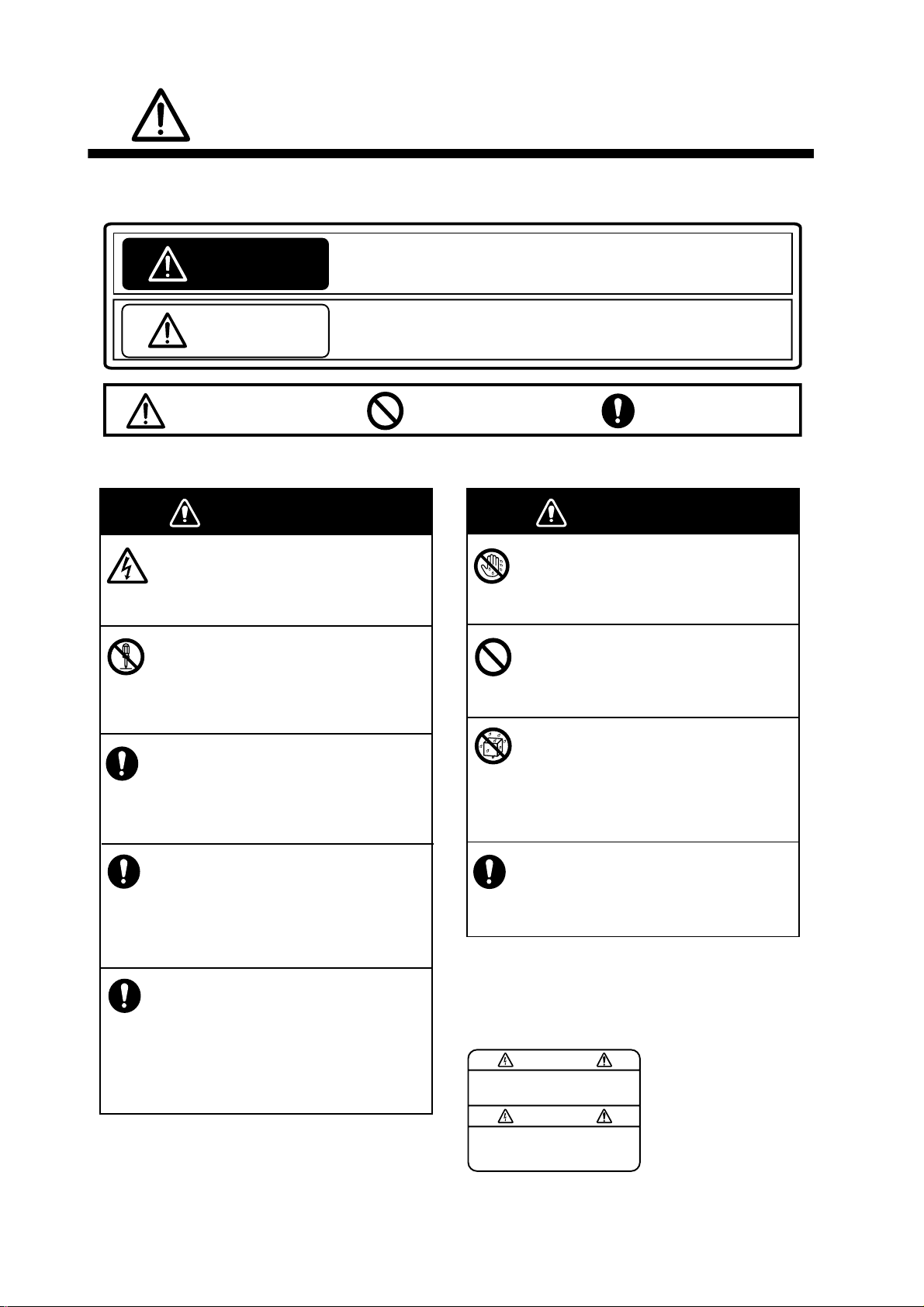
SAFETY INSTRUCTIONS
The user and installer must read the appropriate safety instructions before attempting to install
or operate the equipment.
Indicates a potentially hazardous situation which, if not avoided,
WARNING
CAUTION
Warning, Caution
Safety instructions for the operator
could result in death or serious injury.
Indicates a potentially hazardous situation which, if not avoided,
may result in minor or moderate injury.
Prohibitive Action
Mandatory Action
WARNING
Do not open the equipment.
Only qualified personnel should work
inside the equipment.
Do not disassemble or modify the
equipment.
Fire, electrical shock or serious injury can
result.
Turn off the power immediately if the
equipment is emitting smoke or fire.
Fire or electrical shock can result if the
power is left on.
Turn off the power immediately if water
leaks into the equipment or an object
is dropped inside the equipment.
Continued use can cause fire or electrical
shock.
Turn off the power immediately if you
feel the equipment is acting abnormally.
If the equipment is hot to the touch or is
emitting strange noises, turn off the power
immediately and contact your dealer for
advice.
WARNING
WARNING
Do not operate the equipment with
wet hands.
Electrical shock can result.
Do not place liquid-filled containers
on the top of the equipment.
Electrical shock can result.
Do not install the equipment where
it may be subjected to rain or water
splash.
Fire or electrical shock can result if water
gets inside the equipment.
Use the proper fuse.
Use of a wrong fuse can damage the
equipment and may cause fire.
A warning label is attached to the equipment.
Do not remove this label. If the label is missing
or illegible, contact a FURUNO agent or dealer
about replacement.
To avoid electrical shock,
do not remove cover. No
user-serviceable parts
WARNING
Name: Warning Label (1)
Type: 86-003-1011-3
Code No.: 100-236-233-10
ii
Page 4
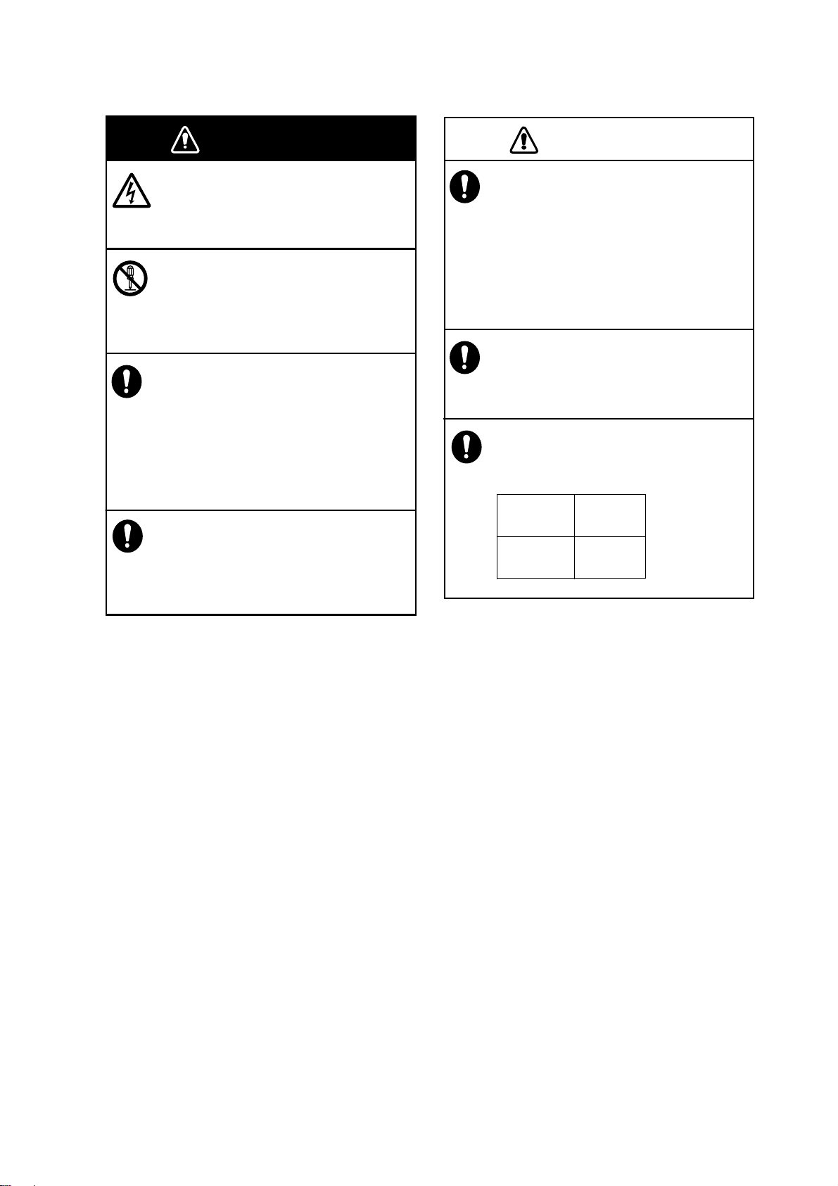
CAUTION
Safety instructions for the installer
SAFETY INSTRUCTIONS
WARNING
Do not open the equipment.
Only qualified personnel should work
inside the equipment.
Turn off the power before beginning
the installation.
Fire or electrical shock can result if the
power is left on.
Be sure no water leaks at the transducer
and temperature sensor.
Water leakage can sink the vessel. Also,
confirm that neither the transducer or
sensor will loosen by vibration. The
installer is solely responsible for the
installation.
Confirm that the power supply voltage
is within the rating of this equipment.
Incorrect voltage will damage the equipment and may cause fire.
WARNING
CAUTION
The transducer cable must be handled
carefully, following the guidelines
below.
• Keep fuels and oils away from the
cable.
• Locate the cable away from chemicals.
• Locate the cable away from locations
where it might be damaged.
Do not apply the power with the
transducer exposed to air.
Damage to the transducer may result.
Observe the following compass safe
distances to prevent interference to a
magnetic compass:
Standard
compass
0.95 m 0.60 m
Steering
compass
iii
Page 5

TABLE OF CONTENTS
FOREWORD....................................................................................................................v
SYSTEM CONFIGURATION ..........................................................................................vi
1. MOUNTING...............................................................................................................1
1.1 Equipment Lis ts........ ... ..................................................................................................1
1.2 Network Sounder..........................................................................................................8
1.3 Transducer.................................................................................................................... 9
1.4 Optional Speed/Temperat ure Sensors ST-02MSB, ST-02PSB................ .. ..................9
1.4.1 Mounting considerations........................................................................................9
1.4.2 Mounting procedure...............................................................................................9
1.5 Optional Temperature Sensors...................................................................................10
1.5.1 Transom mount temperature sensor T-02MTB ...................................................10
1.5.2 Thru-hull temperature sensor T-02MSB, T-03MSB............................................. 11
2. WIRING ...................................................................................................................12
2.1 Wiring Outline........... ...................................................................................................12
2.2 Transducer Cable........................................................................................................ 13
3. INITIAL SETTINGS.................................................................................................15
3.1 Tap Setting..................................................................................................................15
3.2 DIP Switch Sett in g ................... .. .. ............................................................................... 16
3.3 Operation Check......................................................................................................... 18
4. MAINTENANCE......................................................................................................19
4.1 Maintenance................................................................................................................ 19
4.2 Replacing the Fuse ..................................................................................................... 20
4.3 Restoring Default Settings .......................................................................................... 20
iv
Page 6

FOREWORD
A Word to the Owner of the DFF3
Congratulations on your choice of the FURUNO DFF3 Network Sounder. We are confident you
will see why the FURUNO name has become synonymous with quality and reliability.
For 60 years FURUNO Electric Company has enjoyed an enviable reputation for quality marine
electronics equipment. Thi s dedicati on to exc ellence i s furthere d by our extensiv e global net work
of agents and dealers.
This equipment is designed and cons tructed to me et the rigorous demands of the marine envi ronment. However, no machine can perform its intended function unless operated and maintained
properly. Please carefully read and follow the recommended procedures for operation and maintenance.
Thank you for considering and purchasing FURUNO.
Features
The DFF3 network sounder is a dual fr equency echo sounder designed for use with t he FURUNO
NavNet/NavNet vx2/NavNet 3D series. The DFF3 feeds data about underwate r conditions via a
LAN.
A few of the features are
• FURUNO Free Synthesizer (FFS) transceiver design allows use of user-selectable operating
frequencies (28 - 200 kHz).
• Automatic operation selects correct range and gain to show fish echoes and bottom in both
shallow and deep waters.
• Improved discrimination of near-surface fish by eliminating the transmission line.
• Heaving compensation* stabilizes the picture against ship’s pitching and rolling.
* Requires NavNet 3D display device and Satellite Compass SC-30, heading data fed in NMEA
®
2000
• ACCU-FISH
(Transducer 50/200-1T only for use with Na vNet 3D.)
• 1/2/3 kW output
Note: The terms “NavNet” and “Navnet 3D” refer to the models listed below.
Model 17x2 Series, Model 17x2C Series,
Model 17x4 Series, Model 17x4C Series,
GD-1720, GD-1720C,
Model 18x3C(-BB) Series, Model 18x4C(-BB) Series,
Model 19x3C(-BB) Series, Model 19x4C(-BB) Series,
GD-1900C(-BB), GD-1920C(-BB)
format.
®
feature estimates length and depth of individual fish.
Navnet/NavN et vx 2 NavNet 3D
MFDBB, MFD8, MFD12
v
Page 7
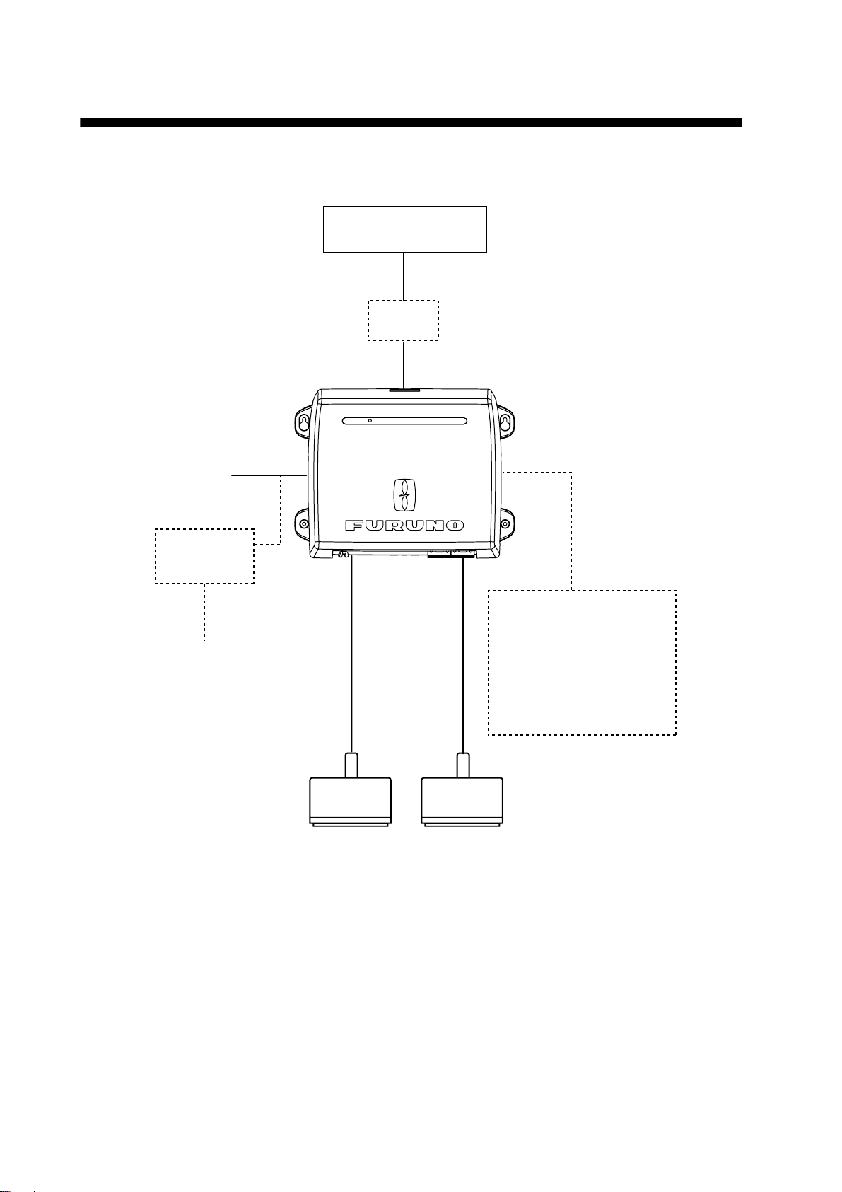
SYSTEM CONFIGURATION
Basic configuration shown with solid line.
NavNet Series
NavNet 3D Series
12-24 VDC
Rectifier
PR-62
100/110/115/
220/230 VAC
1
φ,
50/60 Hz
HUB*
ST-BY
* HUB-100 (For NavNet)
HUB-101 (For NavNet 3D)
Network Sounder
DFF3
NETWORK SOUNDER
DFF3
Speed/Temperature Sensor
ST-02MSB
ST-02PSB
Temperature Sensor
T-02MTB
T-02MSB
T-03MSB
High
Freq.
Transducer
Low
Freq.
Transducer
vi
Page 8

1. MOUNTING
1.1 Equipment Lists
Standard supply
Name Type Code No. Qty Remarks
Network Sounder DFF3
Spare Parts SP02-05601 001-033-740 1 set Fuse
Installation M aterials CP02-08500 000- 011-917 1 set - Power cable (3.5 m)
—
1
- LAN cable (5 m for NavNet 3D)
- Self-tapping screws
Optional supply
Name Type Code No. Remarks
Transducer 1/2/3kW available. See
Thru-hull pipe —
Tank —
Cable Assembly MJ-A6SPF0017-010C 001-159-704-10 1 m, for NavNet
next page for choices.
MJ-A6SPF0017-050C 001-159-705-10 5 m, for NavNet
MJ-A6SPF0017-100C 001-159-706-10 10 m, for Na vNet
MJ-A6SPF0017-200C 001-159-707-11 20 m, for Na vNet
—
MJ-A6SPF0017-300C 001-159-708-11 30 m, for Na vNet
MOD-Z072-020+ 000-167-175- 10 2 m, for NavNet 3D (HUB-101)
MOD-Z072-100+ 001-167-177- 10 10 m, for NavNet 3D (HUB-101 )
Speed/Temperature
Sensor
Temperature
Sensor
Rectifier PR-62 000-013-484 100 VAC
ST-02MSB 000-137-986 Thru-hull mount, steel hull
ST-02PSB 000-137-987 Thru-hull mount, plastic hull
T-02MTB 000-040-026 Transom mount
T-02MSB 000-040-040 Thru-hull mount
T-03MSB 000-040-027 Thru-hull mount
000-013-485 110 VAC
000-013-486 220 VAC
000-013-487 230 VAC
1
Page 9

1. MOUNTING
Transducer, thru-hull pipe and tank com bination s
Output
(W)
1k/1k 28/50 Steel 28F-8
1k/2k 28/200 Steel 28F-8
Frequency
(kHz)
28/88 Steel 28F-8
50/88 Steel 50B-9B
50/200 Steel 50/200-1T or TFB-5000(1) T-603
50/200 Steel 50B-9B
Ship type Transducer
FRP - -
FRP - -
FRP - -
FRP 50/200-1ST - T-603F
Steel 50/200-12M - FRP - -
FRP - -
FRP - -
50B-9B
88B-8
88B-8
200B-8/8B
200B-8/8B
Thru-hull
pipe
TWB-6000(2) T-656
TWB-6000(2) T-657
TWB-6000(2) T-658
TWB-6000(2) T-657
TWB-6000(2) T-658
Tank
88/200 Steel 88B-8
FRP - -
200B-8/8B
TWB-6000(2) T-659
2
Page 10

1. MOUNTING
Output
(W)
2k/2k 28/50 Steel 28F-18
Frequency
(kHz)
28/82 Steel 28F-18
28/88 Steel 28F-18
28/200 Steel 28F-18
38/200 Steel 38BL-9HR
50/82 Steel 50B-12
Ship type Transducer
FRP TRB-1100(2) T-634-F
FRP TRB-1100(2) T-636-F
FRP TRB-1100(2) T-636-F
FRP TRB-1100(2) T-638-F
Steel 28BL-6HR
FRP TRB-1100(2) T-693-F
FRP TRB-1100(2) T-693-F
FRP TRB-1100(2) T-643-F
50B-12
82B-35R
88B-10
200B-8/8B
200B-8/8B
200B-8/8B
82B-35R
Thru-hull
pipe
TFB-7000(2) T-634
TFB-7000(2) T-636
TFB-7000(2) T-636
TFB-7000(2) T-638
TFB-7000(2) T-693
TFB-7000(2) T-693
TFB-7000(2) T-643
Tank
50/88 Steel 50B-12
FRP TRB-1100(2) T-643-F
50/200 Steel 50B-12
FRP TRB-1100(2) T-645-F
Steel 50BL-12HR
FRP TRB-1100(2) T-693-F
Steel 50BL-12
FRP TRB-1100(2) T-693-F
82/200 Steel 82B-35R
FRP TRB-1100(2) T-649-F
88/200 Steel 88B-10
FRP TRB-1100(2) T-649-F
28/107 Steel 28F-18
FRP TRB-1100(2) T-636-F
88B-10
200B-8/8B
200B-8/8B
200B-8/8B
200B-8/8B
200B-8/8B
100B-10R
TFB-7000(2) T-643
TFB-7000(2) T-645
TFB-7000(2) T-693
TFB-7000(2) T-693
TFB-7000(2) T-649
TFB-7000(2) T-649
TFB-7000(2) T-636
3
Page 11

1. MOUNTING
Output
(W)
2k/3k 28/150 Steel 28F-18
3k/2k 68/200 Steel 68F-30H
3k/3k 28/38 Steel 28BL-12HR
Frequency
(kHz)
50/107 Steel 50B-12
50/150 Steel 50B-12
107/200 Steel 100B-10R
Ship type Transducer
FRP TRB-1100(2) T-637-F
FRP TRB-1100(2) T-643-F
FRP TRB-1100(2) T-644-F
FRP TRB-1100(2) T-647-F
FRP TRB-1100(2) T-649-F
FRP TRB-1100(2) T-681-F
Steel 28F/24H
FRP TRB-1100(2) T-681-F
150B-12H
100B-10R
150B-12H
200B-8/8B
200B-8/8B
38BL-15HR
38BL-15HR
Thru-hull
pipe
TFB-7000(2) T-637
TFB-7000(2) T-643
TFB-7000(2) T-644
TFB-7000(2) T-647
TFB-7000(2) T-649
TFB-7000(2) T-681
TFB-7000(2) T-681
Tank
28/50 Steel 28BL-12HR
FRP TRB-1100(2) T-681-F
Steel 28BL-12HR
FRP TRB-1100(2) T-681-F
Steel 28F-24H
FRP TRB-1100(2) T-696-F
Steel 28F-24H
FRP TRB-1100(2) T-681-F
Steel 28F-24H
FRP TRB-1100(2) T-681-F
50BL-24HR
50F-24H
50BL-24H
50BL-24HR
50F-24H
TFB-7000(2) T-681
TFB-7000(2) T-681
TFB-7000(2) T-696
TFB-7000(2) T-681
TFB-7000(2) T-681
4
Page 12

1. MOUNTING
Output
3k/3k
(con’t)
(W)
Frequency
(kHz)
28/88 Steel 28BL-12HR
28/150 Steel 28BL-12HR
28/200 Steel 28BL-12HR
38/50 Steel 38BL-15HR
Ship type Transducer
FRP TRB-1100(2) T-682-F
Steel 28F-24H
FRP TRB-1100(2) T-682-F
FRP TRB-1100(2) T-683-F
Steel 28F-24H
FRP TRB-1100(2) T-683-F
FRP TRB-1100(2) T-683-F
Steel 28F-24H
FRP TRB-1100(2) T-683-F
FRP TRB-1100(2) T-681-F
88F-126H
88F-126H
150B-12H
150B-12H
200B-12H
200B-12H
50BL-24HR
Thru-hull
pipe
TFB-7000(2) T-682
TFB-7000(2) T-682
TFB-7000(2) T-683
TFB-7000(2) T-683
TFB-7000(2) T-683
TFB-7000(2) T-683
TFB-7000(2) T-681
Tank
Steel 38BL-15HR
FRP TRB-1100(2) T-681-F
38/88 Steel 38BL-15HR
FRP TRB-1100(2) T-682-F
38/150 Steel 38BL-15HR
FRP TRB-1100(2) T-683-F
38/200 Steel 38BL-15HR
FRP TRB-1100(2) T-683-F
50/88 Steel 50BL-24H
FRP TRB-1100(2) T-697-F
Steel 50BL-24HR
FRP TRB-1100(2) T-682-F
Steel 50F-24H
FRP TRB-1100(2) T-682-F
50/150 Steel 50BL-24HR
FRP TRB-1100(2) T-683-F
50F-24H
88F-126H
150B-12H
200B-12H
88F-126H
88F-126H
88F-126H
150B-12H
TFB-7000(2) T-681
TFB-7000(2) T-682
TFB-7000(2) T-683
TFB-7000(2) T-683
TFB-7000(2) T-697
TFB-7000(2) T-682
TFB-7000(2) T-682
TFB-7000(2) T-683
Steel 50F-24H
FRP TRB-1100(2) T-683-F
150B-12H
TFB-7000(2) T-683
5
Page 13

1. MOUNTING
Output
3k/3k
(con’t)
(W)
Frequency
(kHz)
50/200 Steel 50BL-24H
68/150 Steel 68F-30H
68/200 Steel 68F-30H
88/150 Steel 88F-126H
88/200 Steel 88F-126H
Ship type Transducer
FRP TRB-1100(2) T-695-F
Steel 50BL-24HR
FRP TRB-1100(2) T-683-F
Steel 50F-24H
FRP TRB-1100(2) T-683-F
FRP TRB-1100(2) T-646-F
FRP TRB-1100(2) T-646-F
FRP TRB-1100(2) T-685-F
FRP TRB-1100(2) T-685-F
200B-12H
200B-12H
200B-12H
150B-12H
200B-12H
150B-12H
200B-12H
Thru-hull
pipe
TFB-7000(2) T-695
TFB-7000(2) T-683
TFB-7000(2) T-683
TFB-7000(2) T-646
TFB-7000(2) T-646
TFB-7000(2) T-685
TFB-7000(2) T-685
Tank
1k 28 Steel 28F-8 TFB-5000(1) T-604
FRP TRB-1000(1) T-604-F
50 Steel 50B-6/6B TFB-5000(1) T-605
FRP TRB-1000(1) T-605-F
Steel 50B-9B TFB-5000(1) T-603
FRP TRB-1000(1) T-603-F
68 Steel 68F-8H TFB-5000(1) T-621
FRP TRB-1000(1) T-621-F
88 Steel 88B-8 TFB-5000(1) T-606
FRP TRB-1000(1) T-606-F
200 Steel 200B-5S TFB-5000(1) T-605
FRP TRB-1000(1) T-605-F
2k 28 Steel 28F-18 TFB-5000(1) T-612
FRP TRB-1000(1) T-612-F
Steel 28BL-6HR TFB-5000(1) T-702
FRP TRB-1000(1) T-702-F
38 Steel 38BL-9HR TFB-5000(1) T-702
FRP TRB-1000(1) T-702-F
6
Page 14

1. MOUNTING
Output
(W)
2k (con’t) 50 Steel 50B-12 TFB-5000(1) T-611
Frequency
(kHz)
82 Steel 82B-35R TFB-5000(1) T-609
88 Steel 88B-10 TFB-5000(1) T-609
200 Steel 200B-8/8B TFB-5000(1) T-608
Ship type Transducer
FRP TRB-1000(1) T-611-F
Steel 50BL-12 TFB-5000(1) T-702
FRP TRB-1000(1) T-702-F
Steel 50BL-12HR TFB-5000(1) T-702
FRP TRB-1000(1) T-702-F
FRP TRB-1000(1) T-609-F
FRP TRB-1000(1) T-609-F
FRP TRB-1000(1) T-608-F
Thru-hull
pipe
Tank
7
Page 15

1. MOUNTING
Output
(W)
3k 28 Steel 28F-24H TFB-4000(1) T-616
Frequency
(kHz)
38 Steel 38BL-15HR TRB-4000(1) T-616-
50 Steel 50F-24H TFB-4000(1) T-616
68 Steel 68F-30H TFB-5000(1) T-614
Ship type Transducer
FRP TRB-1000(1) T-616-F
Steel 28BL-12HR TFB-4000(1) T-616
FRP TRB-1000(1) T-616-F
FRP TRB-1000(1) T-616-F
FRP TRB-1000(1) T-616-F
Steel 50BL-24HR TFB-4000(1) T-616
FRP TRB-1000(1) T-616-F
Steel 50BL-24H TFB-4000(1) T-694
FRP TRB-1000(1) T-694-F
Thru-hull
pipe
Tank
FRP TRB-1000(1) T-614-F
88 Steel 88F-126H TFB-4000(1) T-618
FRP TRB-1000(1) T-618-F
107 Steel 100B-10R TFB-5000(1) T-609
FRP TRB-1000(1) T-609-F
150 Steel 150B-12H TFB-5000(1) T-615
FRP TRB-1000(1) T-615-F
200 Steel 200B-12H TFB-5000(1) T-615
FRP TRB-1000(1) T-615-F
1.2 Network Sounder
The network sounder can be installed on a desktop, deck or on a bulkhead. When selecting a
mounting location for the network sounder, kee p the fol lowing in mind:
• The temperature and humidity at the mounting site shou ld be mod e rate and stable.
• Locate the unit away from exhaust pipes and vents.
• The mounting location should be well ventilated.
• Mount the unit where shock and vibration are minimal.
• Keep the unit away from electromagnetic field-generating equipment such as motors and generators.
• Leave slack in cables for maintenance and servicing ease.
8
Page 16

1. MOUNTING
• A magnetic compass will be affected if the network sounder is placed too close to it. Observe
the compass safe distances noted i n the safety instructions to prevent disturbance to the magnetic compass.
Fasten the network sounder to the mounting location with four se lf-tapping screws (5×20), referring to the outline drawing at the back of this manual for mounti ng dimensions.
1.3 Transducer
The performance of the echo sounder largely depends upon the transducer posi tion. Select a
place least affected by air bubbles since turbulence blocks the sounding path. Further, select a
place least influenced by engine noi se. I t is known that ai r bubbles ar e fe west at the p lace wher e
the bow first falls and the next wave rises, at usual cruising speed.
Note: The face of the trans ducer must be facing the sea bottom in nor mal cruising tr im of the boat.
1.4 Optional Speed/Temperature Sensors
ST-02MSB, ST-02PSB
1.4.1 Mounting considerations
Select a suitable mounting location considering the following points:
• Select a mid-boat flat positi on. The sensor does not have to be in stalled perfectly perpendi cular.
However, the sensor must not be damaged in dry-docking operation.
• Select a place apart from equipment generating heat.
• Select a place in the for ward direction viewing f rom the drain hole, to allow for circulation of cooling water.
• Select a place free from vibration.
• Do not install near the transducer of an echo sounder, to prevent interference to the echo
sounder.
1.4.2 Mounting procedure
1. Dry dock the boat.
2. Make a hole of approx. 51 mm in diameter in the
mounting location.
3. Unfasten locknut and remove the sensor section.
4. Apply high-grade sealant to the flange of the sen-
sor.
5. Pass the sensor casing through the hole.
6. Face the notch on the sensor toward boat's bow
and tighten the flange.
7. Set the sensor section to the sensor casing and
tighten the locknut.
Face "notch"
toward bow.
Flange nut
Coat with
silicone sealant.
51
Brim
φ77
Locknut
123
8. Launch the boat and check for water leakage
around the sensor.
9
Page 17

1. MOUNTING
1.5 Optional Temperat ure Sen sors
1.5.1 Transom mount temperature sensor T-02MTB
• Fix the cable at a convenient location with cable clamp.
• When the cable is led in through the transom board, make a hole of approx. 17 mm in diamete r
to pass the connector. After passing the cable, fill the hole with a sealing compound.
D>50cm
D
5x20
Mount sensor
flush with hull bottom.
10
Page 18

1. MOUNTING
1.5.2 Thru-hull temperature sensor T-02MSB, T-03MSB
Select a suitable mounting location considering the following points:
• Select a mid-boat flat positi on. The sensor does not have to be in stalled perfectly perpendi cular.
However, the location should not be such that the trans ducer may be damaged when the boat
is dry-docked.
• Locate away from equipment which gives off heat.
• Locate away from drain pipes.
• Select a location where vibration is minimal.
T-02MSB T-03MSB
Sensor Holder
cable
8 m
Sensor
cable
8 m
Locknut
Washer
Gasket
Locknut
Locknut
φ21 mm
M20
Coat with
70 mm
φ42 mm
Mounting procedure
1. Drill a hole of 21 mm in diameter in
the mounting location.
2. Pass the sensor cable through the
hole.
3. Pass gasket, washer and locknut
onto cable in that order.
4. Coat the sensor flange with high
quality sealant and then fasten the
sensor with the locknut.
(Torque: max. 59N·m)
5. Launch the boat to check for water
leakage around the sensor.
sealant.
Washer
Gasket
φ25 mm
M24
70 mm
φ50 mm
Holder Guide
Mounting procedure
1. Drill a hole of 25 mm in diameter in the mounting
location.
2. Coat holder guide with high quality sealant, and
pass gasket, washer and locknut onto holder
guide in that order and then tighten the locknut.
3. Set the sensor holder to the holder guide from
inside the boat and then tighten the locknut.
4. Launch the boat to check for water leakage
around the sensor.
Coat with
sealant.
Plate thickness within
25 mm
11
Page 19

2. WIRING
r
2.1 Wiring Outline
Connect the power cable, transducer cables, sensor cable, net work cable and ground wire to their
respective locations on the n etwork sounder. See the next page for how to connect t he transducer
cables.
NavNet 3D
or HUB-101
DFF3
Ground wire
(IV-2 sq)
NavNet
or HUB-100
GROUND
MJ-A6SPF0017 cable
(1/5/10/20/30 m)
MOD-Z072 Cable
- Standard: 5 m
- Option: 2 m, 10 m
NETWORK
12-24VDC
2.8-1.4A
TEMP
(3.5 m)
Temperature or
Speed/Temperature
MJ-A3SPF0013-035C
Black
Sensor
White
H TRANSDUCER L
Shield (green)
High Freq.
Transducer
Low Freq.
Transduce
BATTERY
12 - 24 VDC
Ground
Connect a ground wire (IV-2 sq, local supply) between the
ground terminal and ship’s ground to prevent interfer ence to
the sounder picture. Make the length of th e wire as short as
possible. For FRP vessels, install a ground plate that measures about 20 cm by 30 cm on the outside of the hull bottom and connect the ground wire there.
12
CAUTION
Ground the equipment
to prevent mutual
interference.
Page 20

2. WIRING
r
2.2 Transducer Cable
TD-ID transducer (Airmar make transduc er)
The TD-ID type transducer can be connected to t h is equipment. However, note the following limitations:
• TD-ID transducer cannot be used with NavNet, NavNet vx2.
• TD-ID transducer cannot be used with non-TD-ID transducer.
• Connect single TD-ID transducer to low frequency WAGO connector, regardless of actual frequency.
Cable fabrication
Fabricate the transducer cable as shown below. Separat e the transducer cable well away from
other electric cab les to prevent interf erence to the sounder. T his is especially i mportant in the case
of power cables from televisions and monitors.
Approx. 100
Braided shield
6
Extract cores from here and cut inner materials.
Vinyl tape
20
Draw out braided shield and wrap it around sheath.
Clamp this part with cable clamp.
Sheath
Cable connection
After fabricating the t ransducer cable, connect the transducer cab les to the equipment with WAGO
connectors.
1. Open the cover: Grasp the cover at two sides, spread cover slightl y and lift.
2. Unfasten six screws to remove the shield cover.
3. Detach the two WAGO connectors (low and high frequency) inside the equipment.
WAGO connector
(High frequency)
Opener for WAGO connecto
is here.
WAGO connector
(Low frequency)
13
Page 21

2. WIRING
4. Connect the transducer cabl e to the WAGO connect or, foll owing the i nstruc tions in the figur e
below and the interconnection diag ram. (The opener fo r the WAGO connector i s attached inside the equipment. See the figure above.)
Push
Opener (attached inside the equipment)
1. Twist conductors.
2. Insert opener as directed and press it down.
3. Insert core to hole.
Twist.
Core
4. Release opener.
5. Pull the core to make sure it is correctly inserted.
5. Unfasten the two screws labeled Screw A in the figure below.
6. Loosen the two screws labeled Screw B and slide cable clamp upward.
Cable
clamp
Screw B
Clamping
Screw A
plate
7. Pass the transducer cables through the cable entrance and connect their WAGO connectors
to respective terminals inside the equipment.
8. Slide the cable clamp downward and t ighten screws B and A in tha t order to f asten t he c able
clamp.
Transducer cable
14
Page 22

3. INITIAL SETTINGS
WARNING
Do not open the equipment
unless totally familiar with
electrical circuits.
Only qualified personnel
should work inside the
equipment.
3.1 Tap Setting
This equipment is preprogrammed for use with certain transducers. A jumper wire inside the
equipment is set according to transdu cer model. Check the jumper wire setting instructi ons on the
sticker attached to the chassis. Use the opener attached ins ide the unit to set the jumper wire. One
end of the jumper wire is connected to COMMON; connect the other end to A - E in the jumper
block as applicable.
For transducers not programmed, for example, Airmar make TD-ID transducer, consult a
FURUNO agent or dealer for advice.
Tap Setting LED
EDCBA
High Freq.
EDCBA
Low Freq.
Tap setting plug
(High freq.)
Tap setting plug
(Low freq.)
Common
Jumper
wire
D
E
Set in appropriate slot
according to sticker.
A
C
B
Note 1: For NavNet, the tap settings shown on the NETWORK SOUNDER SETUP are different
from actual ones. Therefore, follow the inst ructions on the sticker inside the equipment.
Note 2: For transducers 50/200-1ST, 50/200-1T an d 50/200-12M, use the tap settings f or 50/2001T (50: Tap B, 200: Tap C).
15
Page 23

3. INITIAL SETTINGS
3.2 DIP Switch Setting
The DIP switch S2 sets up the system according to the equipment connected. In the default setting
all switches (1-8) are OFF. The DIP switch S3 should not be adjust ed; leave all switches in the
OFF position.
1-8
S2
OFF
ON
1-8
S3
OFF
ON
DIP Switches
DIP switch S2 description
Switch
No.
1 Power on/off b y NavNe t or NavNet
3D
2 Automatic/Manual IP address
selection
Function Setting
OFF: Power sync (for NavNet 3D)
ON: No power sync (for NavNet)
OFF: Automatic IP address assignment. Use this
setting for NavNet 3D.
*1
ON: Manual I P address assi gnment. Use th is setting
for NavNet, and r efer to the tab le on the next page f or
IP addresses.
3 - 6 Manual IP address assignment Valid when switch no. 2 is ON. Fo r connection of mul-
tiple network sounders, assign each one an IP address with the Mode DIP switch, referring to the table
on the next page.
7 Restore defaul t settings (other than
See section 4.3.
LAN and transducer)
8 Restore ALL defa ult settings See section 4. 3.
*1: Power sync setting enabled at NavNet 3D.
16
Page 24

3. INITIAL SETTINGS
DIP SW S2 setting, sounder and IP address
SW No.3 SW No.4 SW No.5 SW No.6 Host Name IP Address
OFF OFF OFF OFF SOUNDER 172.031.092.001
ON OFF OFF OFF SOUNDER1 172.031.092.011
OFF ON OFF OFF SOUNDER2 172.031.092.012
ON ON OFF OFF SOUNDER3 172.031.092.013
OFF OFF ON OFF SOUNDER4 172.031.092.014
ON OFF ON OFF SOUNDER5 172.031.092.015
OFF ON ON OFF SOUNDER6 172.031.092.016
ON ON ON OFF SOUNDER7 172.031.092.017
OFF OFF OFF ON SOUNDER8 172.031.092.018
ON OFF OFF ON SOUNDER9 172.031.092.019
OFF ON OFF ON
ON ON OFF ON
OFF OFF ON ON
ON OFF ON ON
OFFONONON
ON ON ON ON
Transducer setting at NavNet/NavNet3D
After setting up the transducer at the DFF3, set transducer type at NavNet, NavNet 3D. See respective Installation Manual for the procedure.
17
Page 25

3. INITIAL SETTINGS
3.3 Operation Ch ec k
For NavNet, the DFF3 is powered on/off from ship’s switchboard. For NavNet 3D, it is powered
on/off from the display unit . The LED on the c over of the DFF3 lig hts or bl inks accor ding t o e quipment state, as described in the table below.
LED state and meaning
LED state Meaning
Lighting continuously • Standby state. (If, for NavN et, NavNet 3D no signal is received
via LAN for more than 10 minutes, the equipment automatically
goes into standby to lessen power consumption.)
• Power on (20 seconds during initialization)
• IP address not set
Blinking every two seconds Normal operation
Blinking every 0.4 seconds Transducer settings at NavNet, NavNet 3D not properly set.
LED
18
Page 26

4. MAINTENANCE
WARNING
ELECTRICAL SHOCK HAZARD
Do not open the equipment.
Only qualified personnel
should work inside the
equipment.
Do not apply paint, anti-corrosive
sealant or contact spray to coating
or plastic parts of the equipment.
Those items contain organic solvents
that can damage coating and plastic
parts, especially plastic connectors.
NOTICE
4.1 Maintenance
Regular maintenance is essential for good per formance. Check the items listed in th e table below
at the suggested interval to help keep your equipment in good shape for years to come.
Item Check point, action Check interval
Transducer cables Check that cables are tightly f astened and are not
damaged. Refasten if necessar y. Repl ace if da maged.
Once a month
Power cable, sensor
cable
Ground Check for corrosi on. Clean if necessary. Once a month
Power supply volta ge Check voltage. If out of rating correct problem. Once a month
Cleaning the network
sounder’s cabinet
Transducer Marine life on the transducer face will result in a
Check that these cables are tightly fastened and
not damaged. Refast en if necessary. Replace if
damaged.
Dust or dirt on th e cabinet may be r emoved with a
dry cloth. Do not use ch emical- based cleaner s to
clean the cabine t; they can remove markin gs and
damage the cabinet.
gradual decrease in sensitivity. Check the transducer face for cleanliness each time the boat is
dry-docked. Careful ly remove any marine life with
a piece of wood or fine-grade sandpaper.
Once a month
Once a month
When vessel is
dry-docked
19
Page 27

4. MAINTENANCE
4.2 Replacing the Fuse
The 5A fuse (Type: FGBO-A 125V 5A PBF, Code No. 000-155-85 3-10) in the snap- in fuse holder
on the power cable protects the equi pment from equipment f ault and rever se polarity of t he ship's
mains. If the equipment cannot be powered, the fuse may have blown. Find out the cause for
blown fuse before replacing it. If the fuse blows again after repl acement, contact a FURUNO agent
or dealer for advice.
WARNING
Use the proper fuse.
Use of a wrong fuse can damage the equipment and cause fire.
4.3 Restoring Default Settings
This procedure restores all default sounder settings on the NavNet, NavNet 3D. You can restore
all default settings or restore th ose other than transducer and LAN. This procedure should only be
performed by a suitably qualified FURUNO technician.
1. Disconnect the power and LAN cables from the DFF3.
2. Turn on the #1 and #2 switches of the Mode switch. See section 3.2 for the location.
3. Turn on the #7 or #8 switch of the Mode switch as applicable.
#7: Restore default settings other than LAN and transducer.
#8: Restore all default sett ings. Use this when changing transducers.
4. Connect the power cable to the DFF3, and turn on the power at the ship’s switchboard.
5. The LED blinks (every four seconds) when default settings are completely restored.
20
Page 28

PACKING LIST
A-1
DFF3-J/E
02GF-X-9851 -0
1/1
N A M E
O U T L I N E
DESCRIPTION/CODE №
ユニット UNIT
ネットワーク魚探
NETWORK SOUNDER
DFF3
000-011-916-00
予備品 SPARE PARTS SP02-05601
ヒューズ
FUSE GLASS TUBE TYPE
FGB0-A 125V 5A PBF
000-155-853-10
工事材料 INSTALLATION MATERIALS CP02-08500
+トラスタッピンネジ 1シュ
SELF-TAPPING SCREW
5X20 SUS304
000-162-608-10
ケーブル(組品)LAN
CABLE ASSY.
MOD-Z072-050+
000-167-176-10
ケーブル組品MJ
CABLE ASSY.
MJ-A3SPF0013-035C(5A)
000-157-939-10
図書 DOCUMENT
取扱説明書
OPERATOR'S MANUAL
OM*-20370-*
000-168-581-1*
Q'TY
1
2
4
1
1
1
**
コ-ド番号末尾の[**]は、選択品の代表コードを表します。
CODE NUMBER ENDING WITH "**" INDICATES THE CODE NUMBER OF REPRESENTATIVE MATERIAL.
型式/コード番号が2段の場合、下段より上段に代わる過渡期品であり、どちらかが入っています。 なお、品質は変わりません。
TWO TYPES AND CODES MAY BE LISTED FOR AN ITEM. THE LOWER PRODUCT MAY BE SHIPPED IN PLACE OF THE UPPER
PRODUCT. QUALITY IS THE SAME.
(略図の寸法は、参考値です。 DIMENSIONS IN DRAWING FOR REFERENCE ONLY.)
C2037‑Z01‑A
Page 29

FURUNO
SPECIFICATIONS OF NET WORK SOUNDER
DFF3
1 GENERAL
1.1 TX frequency 28-200 kHz, two frequencies alternately transmitted (selectable)
1.2 Output power 1/2/3 kW nominal
1.3 Amplifier type Wide dynamic range linear amplifier (double superheterodyne)
1.4 Depth range and Pulse repetition rate (PRR)
200 kHz, TX rate: 20
2 INTERFACE
Range (m) PRR ( /min.)
2 2403 (max)
5 2403
10 1621
40 476
100 222
200 117
400 58
1200 34
DFF3
2.1 Number of port LAN: 1 port, Transducer: 2 port, Temp/speed sensor: 1 port
2.2 Network Ethernet 10BASE-T/100BASE-TX
3 POWER SUPPLY
3.1 Network sounder 12-24 VDC: 2.8-1.4 A
3.2 Rectifier (PR-62, option) 100/110/220/230 VAC, 1 phase, 50/60 Hz
4 ENVIRONMENTAL CONDITION
4.1 Ambient temperature -15°C to +55°C
4.2 Relative humidity 93% at 40°C
4.3 Degree of protection IP20
4.4 Vibration requirement IEC 60945
5 COATING COLOR
N2.5 (not changed)
SP - 1 E2037S01A
080318
Page 30

D-1
Jan.18'08R.Esumi
Page 31

*2
S-1
*2
P
HUB-101
ETHERNET HUB
TXN
RXP
TXN
RXP
または OR
マルチファンクションディスプレイ
RXNNCNC
NC
NC
P
P
RXN
P_SW-P
P_SW-N
MULTI-FUNCTION DISPLAY
P
NC
MFD8/12
8
*2
MJ-A6SPF0017-050C
8
NC
1B1 02P6358
43
イーサネットハブ
TXP
1234567
RJ45
MOD-Z072-050+,5m(2/10m *2)
RJ45
1234567
J19
TXP
DFF3
NETWORK SOUNDER
2
ネットワーク魚探
(+)
(-)
123
SHIELD
SHIELD
TEMP
J2
12345
指示部
E_TD-P
12345
MJ-A6SPF
5m,φ6 (MAX.30m)
KP OUT
123
KPO
J23(PH4P)
TEMP_0V
SPEED
12V_P
DISPLAY UNIT
E_TD-N
GND
GND
6
(NAVNET 1/VX2)
E_RD-P
E_RD-NNCSHIELD
KP IN
4
KPI
GND
02P6360
1B3
6
NET KPNET_KP1_IO
123
GND
J24(XH3P)
SHIELD
J25(XH3P)
02P63591B2
123
GND
SHIELD
NET_KP2_IO
TD_HF-L
GND32
TD_HF-H
J7
TD_LF-L
GND
TD_LF-H
J6
TEMP_XDR-H
XDR-H_GND
TDID_XDR-H
NC
TD_HF-L
GND
TD_HF-H
J7(231-337/001-000)
TEMP_XDR-HL
XDR-HL_GND
TDID_XDR-HL
NC
TD_LF-L
GND
TD_LF-H
J6(231-337/001-000)
DFF3
ネットワーク魚探
相互結線図
NETWORK SOUNDER
INTERCONNECTION DIAGRAM
TITLE
名称
ミドリ
GRN
アオ
1
3
2
1
7
6
5
4
3
2
1
7
6
5
4
3
2
1
BLU
クロ BLK
アカ RED
BLK
RED
BLK
RED
*2
10m(1T/12M)
15m(1ST)
50/200-1T/1ST
送受波器
8/10/15m,φ12
HF
8/10/15m,φ12
LF
50/200-12M
TRANSDUCER
T.YAMASAKI
Feb. 26 '08
DRAWN
CHECKED
NAME
02-161-1001-0
REF.No.
kg
T.TAKENO
SCALE MASS
C2037-C01- A
DWG.No.
26/Mar/08R.Esumi
Feb. 27 '08
APPROVED
*1
MJ-A3SPF J1
WHT
BLK
シロクロミドリ
5A
MJ-A3SPF0013-035C,3.5m
1
(+)
(-)
GRN
GND
DPYC-1.5 *1
MJ-A6SPF
8m
GND
(-)
(+)
1 23
56
整流器
*2
RECTIFIER
PR-62
IV-2sq.
ST-02MSB/PSB
T-02MTB/MSB
TEMP/SPEED
SENSOR
T-03MSB
水温・船速
*1
IV-2sq.
センサー
100/110/
12-24VDC
220/230VAC
1φ,50/60Hz
NOTE
*1: SHIPYARD SUPPLY.
注記
*1)造船所手配。
*2)オプション。
A
B
C
*2: OPTION.
Page 32

9-52 Ashihara-cho,
*
00016858210
**00016858210
*
Nishinomiya, 662-8580, JAPAN
Telephone : +81-(0)798-65-2111
Fax :+81-(0)798-65-4200
The paper used in this manual
is elemental chlorine free.
・FURUNO Authorized Distributor/Dealer
All rights reserved.
Pub. No. OME-20370-A
(DAMI ) DFF3
Printed in Japan
A : MAR 2008
.
*00016858210**00016858210*
* 0 0 0 1 6 8 5 8 2 1 0 *
 Loading...