

Page 1
OPERATOR'S MANUAL
NETWORK SOUNDER
Model
DFF3
www.furuno.com
Page 2

Page 3
IMPORTANT NOTICES
General
• This manual has been authored with simplified grammar, to meet the needs of international users.
• The operator of this equipment must read and follow the descriptions in this manual. Wrong operation or maintenance can cancel the warranty or cause injury.
• Do not copy any part of this manual without written permission from FURUNO.
• If this manual is lost or worn, contact your dealer about replacement.
• The contents of this manual and equipment specifications can change without notice.
• The example screens (or illustrations) shown in this manual can be different from the screens
you see on your display. The screens you see depend on your system configuration and equipment settings.
• Save this manual for future reference.
• Any modification of the equipment (including software) by persons not authorized by FURUNO
will cancel the warranty.
• All brand and product names are trademarks, registered trademarks or service marks of their
respective holders.
How to discard this product
Discard this product according to local regulations for the disposal of industrial waste. For disposal
in the USA, see the homepage of the Electronics Industries Alliance (http://www.eiae.org/) for the
correct method of disposal.
How to discard a used battery
Some FURUNO products have a battery(ies). To see if your product has a battery, see the chapter
on Maintenance. Follow the instructions below if a battery is used. Tape the + and - terminals of
battery before disposal to prevent fire, heat generation caused by short circuit.
In the European Union
The crossed-out trash can symbol indicates that all types of batteries
must not be discarded in standard trash, or at a trash site. Take the
used batteries to a battery collection site according to your national
legislation and the Batteries Directive 2006/66/EU.
In the USA
The Mobius loop symbol (three chasing arrows) indicates that Ni-Cd
and lead-acid rechargeable batteries must be recycled. Take the used
batteries to a battery collection site according to local laws.
In the other countries
Ni-Cd Pb
Cd
There are no international standards for the battery recycle symbol. The number of symbols can
increase when the other countries make their own recycle symbols in the future.
i
Page 4
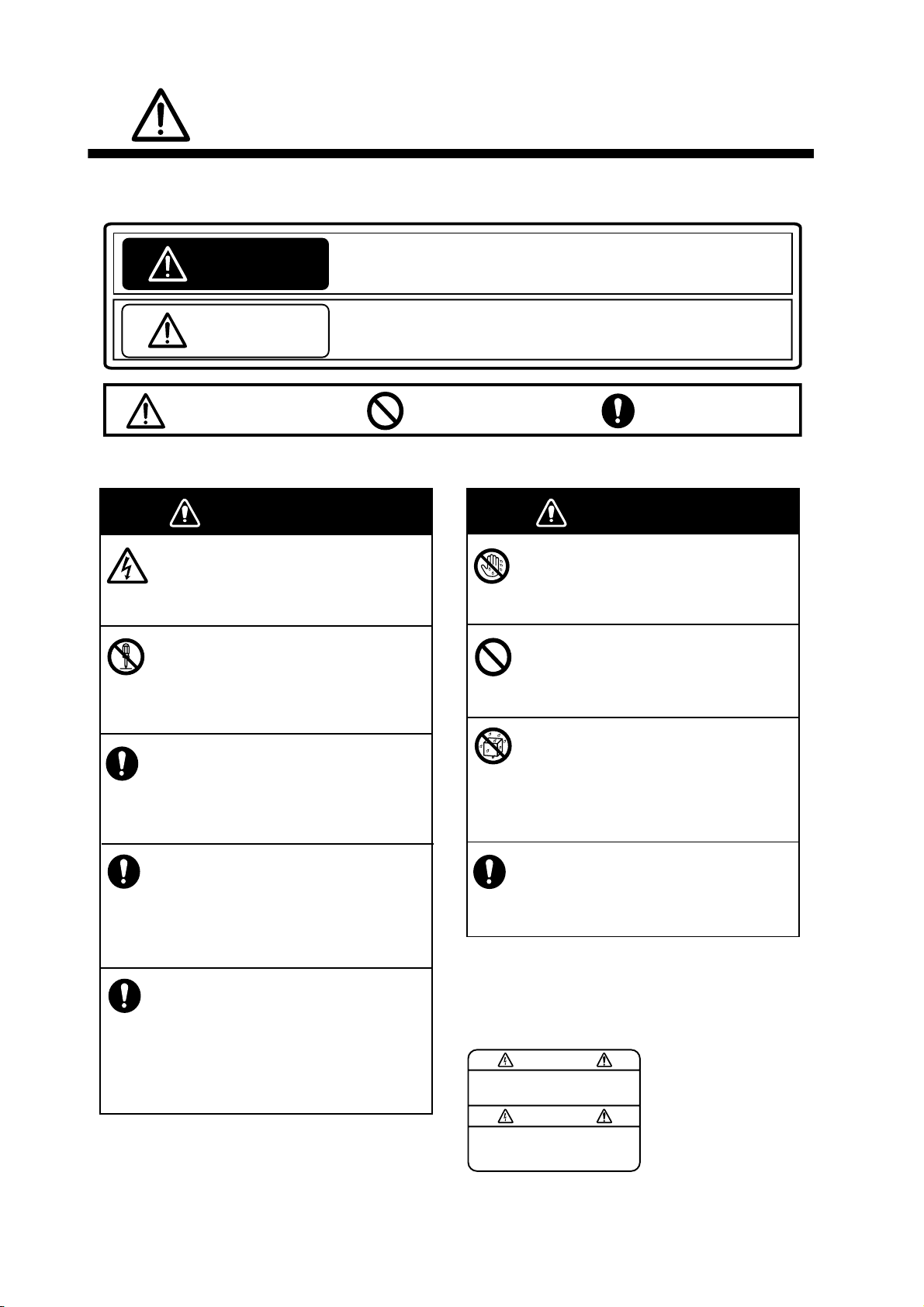
SAFETY INSTRUCTIONS
The user and installer must read the appropriate safety instructions before attempting to install
or operate the equipment.
Indicates a potentially hazardous situation which, if not avoided,
WARNING
CAUTION
Warning, Caution
Safety instructions for the operator
could result in death or serious injury.
Indicates a potentially hazardous situation which, if not avoided,
may result in minor or moderate injury.
Prohibitive Action
Mandatory Action
WARNING
Do not open the equipment.
Only qualified personnel should work
inside the equipment.
Do not disassemble or modify the
equipment.
Fire, electrical shock or serious injury can
result.
Turn off the power immediately if the
equipment is emitting smoke or fire.
Fire or electrical shock can result if the
power is left on.
Turn off the power immediately if water
leaks into the equipment or an object
is dropped inside the equipment.
Continued use can cause fire or electrical
shock.
Turn off the power immediately if you
feel the equipment is acting abnormally.
If the equipment is hot to the touch or is
emitting strange noises, turn off the power
immediately and contact your dealer for
advice.
WARNING
WARNING
Do not operate the equipment with
wet hands.
Electrical shock can result.
Do not place liquid-filled containers
on the top of the equipment.
Electrical shock can result.
Do not install the equipment where
it may be subjected to rain or water
splash.
Fire or electrical shock can result if water
gets inside the equipment.
Use the proper fuse.
Use of a wrong fuse can damage the
equipment and may cause fire.
A warning label is attached to the equipment.
Do not remove this label. If the label is missing
or illegible, contact a FURUNO agent or dealer
about replacement.
To avoid electrical shock,
do not remove cover. No
user-serviceable parts
WARNING
Name: Warning Label (1)
Type: 86-003-1011-3
Code No.: 100-236-233-10
ii
Page 5
CAUTION
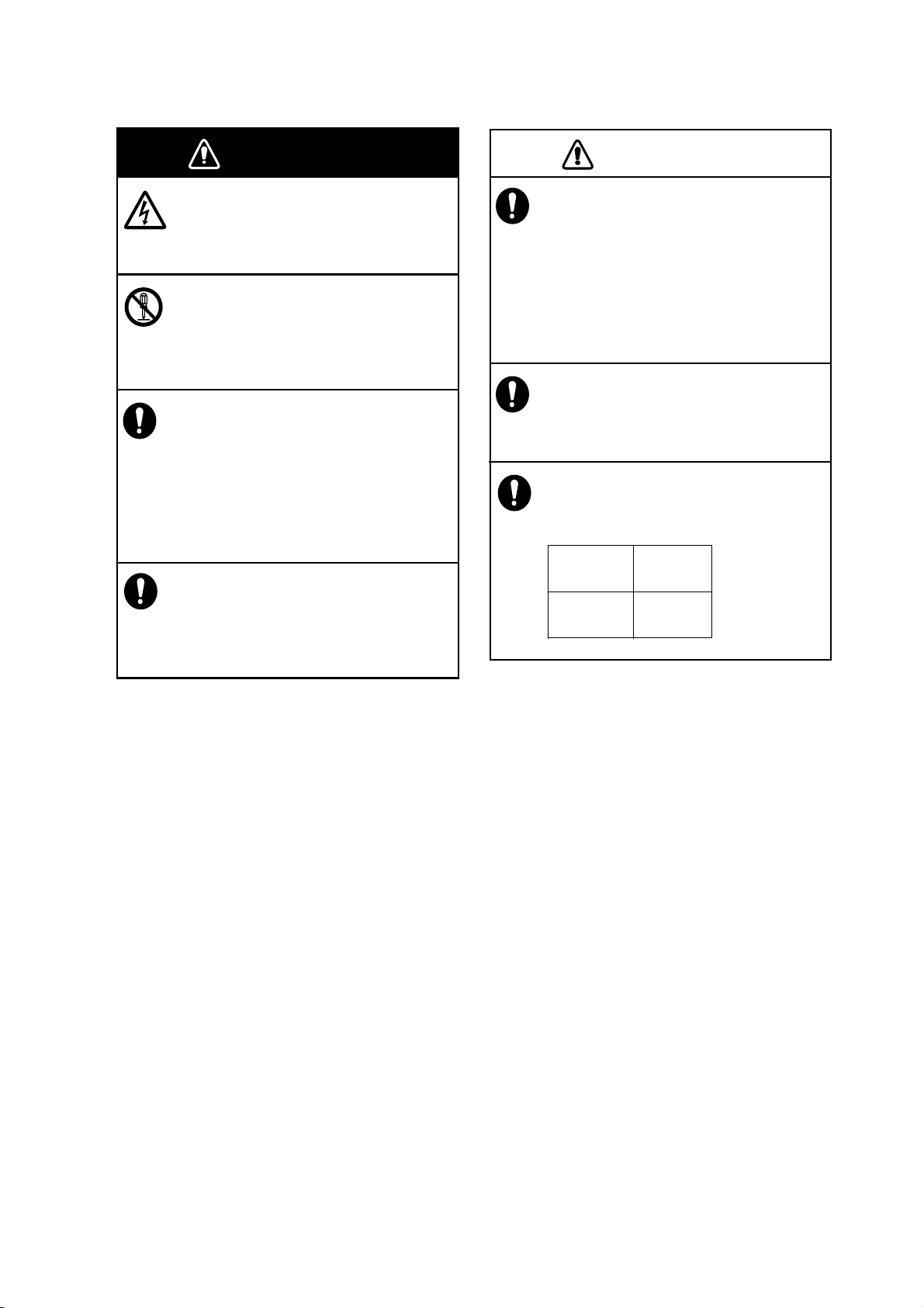
Safety instructions for the installer
SAFETY INSTRUCTIONS
WARNING
Do not open the equipment.
Only qualified personnel should work
inside the equipment.
Turn off the power before beginning
the installation.
Fire or electrical shock can result if the
power is left on.
Be sure no water leaks at the transducer
and temperature sensor.
Water leakage can sink the vessel. Also,
confirm that neither the transducer or
sensor will loosen by vibration. The
installer is solely responsible for the
installation.
Confirm that the power supply voltage
is within the rating of this equipment.
Incorrect voltage will damage the equipment and may cause fire.
WARNING
CAUTION
The transducer cable must be handled
carefully, following the guidelines
below.
• Keep fuels and oils away from the
cable.
• Locate the cable away from chemicals.
• Locate the cable away from locations
where it might be damaged.
Do not apply the power with the
transducer exposed to air.
Damage to the transducer may result.
Observe the following compass safe
distances to prevent interference to a
magnetic compass:
Standard
compass
0.95 m 0.60 m
Steering
compass
iii
Page 6

TABLE OF CONTENTS
FOREWORD....................................................................................................................v
SYSTEM CONFIGURATION ..........................................................................................vi
1. MOUNTING...............................................................................................................1
1.1 Equipment Lis ts........... .. ................................................................................................1
1.2 Network Sounder..........................................................................................................8
1.3 Transducer....................................................................................................................9
1.4 Optional Speed/Temperat ure Sensors ST-02MSB, ST-02PSB....................................9
1.4.1 Mounting considerations ........................................................................................9
1.4.2 Mounting procedure...............................................................................................9
1.5 Optional Temperature Sensors...................................................................................10
1.5.1 Transom mount temperature sensor T-02MTB ...................................................10
1.5.2 Thru-hull temperature sensor T-02MSB, T-03MSB............................................. 11
2. WIRING ...................................................................................................................12
2.1 Wiring Outline.............. ................................................................................................12
2.2 Transducer Cable........................................................................................................13
3. INITIAL SETTINGS.................................................................................................15
3.1 Tap Setting..................................................................................................................15
3.2 DIP Switch Sett in g ................... .. .. ............................................................................... 16
3.3 Operation Check.........................................................................................................18
4. MAINTENANCE......................................................................................................19
4.1 Maintenance................................................................................................................ 19
4.2 Replacing the Fuse.....................................................................................................20
4.3 Restoring Default Settings .......................................................................................... 20
iv
Page 7

FOREWORD
A Word to the Owner of the DFF3
Congratulations on your choice of the FURUNO DFF3 Network Sounder. We are confident you
will see why the FURUNO name has become synonymous with quality and reliability.
Since 1948, FURUNO Electric Company has enjoyed an enviable reputation for quality marine
electronics equipment. This dedication to excellence is furthered by our extensive global network
of agents and dealers.
This equipment is designed and constructed to meet the rigorous demands of the marine environment. However, no machine can perform its intended function unless operated and maintained
properly. Please carefully read and follow the recommended procedures for operation and maintenance.
Thank you for considering and purchasing FURUNO.
Features
The DFF3 network sounder is a dual frequency echo sounder designed for use with the FURUNO
NavNet, NavNet vx2, NavNet 3D and NavNet TZtouch series. The DFF3 feeds data about underwater conditions via a LAN.
• FURUNO Free Synthesizer (FFS) transceiver design allows use of user-selectable operating
frequencies (28 - 200 kHz).
• Automatic operation selects correct range and gain to show fish echoes and bottom in both
shallow and deep waters.
• Improved discrimination of near-surface fish by eliminating the transmission line.
• Heaving compensation* stabilizes the picture against ship’s pitching and rolling. * Requires
NavNet 3D/TZtouch display device plus Satellite Compass SC-30.
• Approximate fish length calculation available with conenction of transducer 50/200-1T. (NavNet
3D and TZtouch only.)
• 1/2/3 kW output
Note: The terms “NavNet”, NavNet vx2”, “NavNet 3D” and “NavNet TZtouch” refer to the models
listed below.
NavNet/NavNet vx2 NavNet 3D NavNet TZtouch
Model 17x2 Series, Model 17x2C Series, Model 17x4
Series, Model 17x4C Series, GD-1720, GD-1720C,
Model 18x3C(-BB) Series, Model 18x4C(-BB) Series,
Model 19x3C(-BB) Series, Model 19x4C(-BB) Series,
GD-1900C(-BB), GD-1920C(-BB)
MFD8/12/BB TZ9, TZ14
v
Page 8
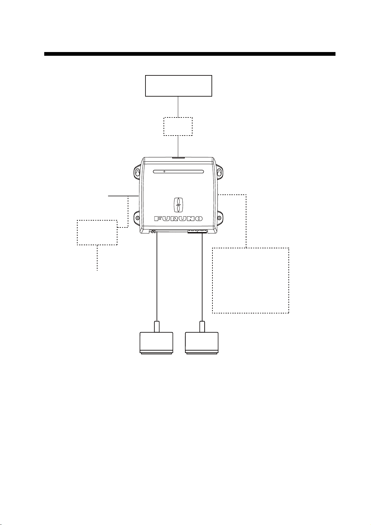
SYSTEM CONFIGURATION
NavNet Series
12-24 VDC
Rectifier
PR-62
100/110/115/
220/230 VAC
1
φ,
50/60 Hz
HUB*
ST-BY
* HUB-100 (For NavNet/NavNet vx2)
HUB-101 (For NavNet 3D/TZtouch)
Network Sounder
DFF3
NETWORK SOUNDER
DFF3
Speed/Temperature Sensor
ST-02MSB
ST-02PSB
Temperature Sensor
T-02MTB
T-02MSB
T-03MSB
High
Freq.
Transducer
Low
Freq.
Transducer
vi
Page 9
1. MOUNTING
1.1 Equipment Lists
Standard supply
Name Type Code No. Qty Remarks
Network Sounder DFF3 — 1
Spare Parts SP02-05601 001-033-740 1 set Fuse
Installation Materials CP02-08500 000-011-917 1 set - Power cable (3.5 m)
- LAN cable (5 m)
- Self-tapping screws
Optional supply
Name Type Code No. Remarks
Transducer 1/2/3kW available. See
Thru-hull pipe —
Tank —
Cable Assembly MJ-A6SPF0017-010C 001-159-704-10 1 m, for NavNet
Speed/Temperature Sensor
Temperature
Sensor
next page for choices.
MJ-A6SPF0017-050C 001-159-705-10 5 m, for NavNet
MJ-A6SPF0017-100C 001-159-706-10 10 m, for NavNet
MJ-A6SPF0017-200C 001-159-707-11 20 m, for NavNet
MJ-A6SPF0017-300C 001-159-708-11 30 m, for NavNet
MOD-Z072-020+ 000-167-175-10 2 m, for HUB-101
MOD-Z072-100+ 001-167-177-10 10 m, for HUB-101
ST-02MSB 000-137-986 Thru-hull mount, steel hull
ST-02PSB 000-137-987 Thru-hull mount, plastic hull
T-02MTB 000-040-026 Transom mount
T-02MSB 000-040-040 Thru-hull mount
T-03MSB 000-040-027 Thru-hull mount
—
Rectifier PR-62 000-013-484 100 VAC
000-013-485 110 VAC
000-013-486 220 VAC
000-013-487 230 VAC
1
Page 10

1. MOUNTING
Transducer, thru-hull pipe and tank com bination s
Output
(W)
1k/1k 28/50 Steel 28F-8
1k/2k 28/200 Steel 28F-8
Frequency
(kHz)
28/88 Steel 28F-8
50/88 Steel 50B-9B
50/200 Steel 50/200-1T or TFB-5000(1) T-603
50/200 Steel 50B-9B
Ship type Transducer
FRP - -
FRP - -
FRP - -
FRP 50/200-1ST - T-603F
Steel 50/200-12M - FRP - -
FRP - -
FRP - -
50B-9B
88B-8
88B-8
200B-8/8B
200B-8/8B
Thru-hull
pipe
TWB-6000(2) T-656
TWB-6000(2) T-657
TWB-6000(2) T-658
TWB-6000(2) T-657
TWB-6000(2) T-658
Tank
88/200 Steel 88B-8
FRP - -
200B-8/8B
TWB-6000(2) T-659
2
Page 11

1. MOUNTING
Output
(W)
2k/2k 28/50 Steel 28F-18
Frequency
(kHz)
28/82 Steel 28F-18
28/88 Steel 28F-18
28/200 Steel 28F-18
38/200 Steel 38BL-9HR
50/82 Steel 50B-12
Ship type Transducer
FRP TRB-1100(2) T-634-F
FRP TRB-1100(2) T-636-F
FRP TRB-1100(2) T-636-F
FRP TRB-1100(2) T-638-F
Steel 28BL-6HR
FRP TRB-1100(2) T-693-F
FRP TRB-1100(2) T-693-F
FRP TRB-1100(2) T-643-F
50B-12
82B-35R
88B-10
200B-8/8B
200B-8/8B
200B-8/8B
82B-35R
Thru-hull
pipe
TFB-7000(2) T-634
TFB-7000(2) T-636
TFB-7000(2) T-636
TFB-7000(2) T-638
TFB-7000(2) T-693
TFB-7000(2) T-693
TFB-7000(2) T-643
Tank
50/88 Steel 50B-12
FRP TRB-1100(2) T-643-F
50/200 Steel 50B-12
FRP TRB-1100(2) T-645-F
Steel 50BL-12HR
FRP TRB-1100(2) T-693-F
Steel 50BL-12
FRP TRB-1100(2) T-693-F
82/200 Steel 82B-35R
FRP TRB-1100(2) T-649-F
88/200 Steel 88B-10
FRP TRB-1100(2) T-649-F
28/107 Steel 28F-18
FRP TRB-1100(2) T-636-F
88B-10
200B-8/8B
200B-8/8B
200B-8/8B
200B-8/8B
200B-8/8B
100B-10R
TFB-7000(2) T-643
TFB-7000(2) T-645
TFB-7000(2) T-693
TFB-7000(2) T-693
TFB-7000(2) T-649
TFB-7000(2) T-649
TFB-7000(2) T-636
3
Page 12

1. MOUNTING
Output
(W)
2k/3k 28/150 Steel 28F-18
3k/2k 68/200 Steel 68F-30H
3k/3k 28/38 Steel 28BL-12HR
Frequency
(kHz)
50/107 Steel 50B-12
50/150 Steel 50B-12
107/200 Steel 100B-10R
Ship type Transducer
FRP TRB-1100(2) T-637-F
FRP TRB-1100(2) T-643-F
FRP TRB-1100(2) T-644-F
FRP TRB-1100(2) T-647-F
FRP TRB-1100(2) T-649-F
FRP TRB-1100(2) T-681-F
Steel 28F/24H
FRP TRB-1100(2) T-681-F
150B-12H
100B-10R
150B-12H
200B-8/8B
200B-8/8B
38BL-15HR
38BL-15HR
Thru-hull
pipe
TFB-7000(2) T-637
TFB-7000(2) T-643
TFB-7000(2) T-644
TFB-7000(2) T-647
TFB-7000(2) T-649
TFB-7000(2) T-681
TFB-7000(2) T-681
Tank
28/50 Steel 28BL-12HR
FRP TRB-1100(2) T-681-F
Steel 28BL-12HR
FRP TRB-1100(2) T-681-F
Steel 28F-24H
FRP TRB-1100(2) T-696-F
Steel 28F-24H
FRP TRB-1100(2) T-681-F
Steel 28F-24H
FRP TRB-1100(2) T-681-F
50BL-24HR
50F-24H
50BL-24H
50BL-24HR
50F-24H
TFB-7000(2) T-681
TFB-7000(2) T-681
TFB-7000(2) T-696
TFB-7000(2) T-681
TFB-7000(2) T-681
4
Page 13

1. MOUNTING
Output
3k/3k
(con’t)
(W)
Frequency
(kHz)
28/88 Steel 28BL-12HR
28/150 Steel 28BL-12HR
28/200 Steel 28BL-12HR
38/50 Steel 38BL-15HR
Ship type Transducer
FRP TRB-1100(2) T-682-F
Steel 28F-24H
FRP TRB-1100(2) T-682-F
FRP TRB-1100(2) T-683-F
Steel 28F-24H
FRP TRB-1100(2) T-683-F
FRP TRB-1100(2) T-683-F
Steel 28F-24H
FRP TRB-1100(2) T-683-F
FRP TRB-1100(2) T-681-F
88F-126H
88F-126H
150B-12H
150B-12H
200B-12H
200B-12H
50BL-24HR
Thru-hull
pipe
TFB-7000(2) T-682
TFB-7000(2) T-682
TFB-7000(2) T-683
TFB-7000(2) T-683
TFB-7000(2) T-683
TFB-7000(2) T-683
TFB-7000(2) T-681
Tank
Steel 38BL-15HR
FRP TRB-1100(2) T-681-F
38/88 Steel 38BL-15HR
FRP TRB-1100(2) T-682-F
38/150 Steel 38BL-15HR
FRP TRB-1100(2) T-683-F
38/200 Steel 38BL-15HR
FRP TRB-1100(2) T-683-F
50/88 Steel 50BL-24H
FRP TRB-1100(2) T-697-F
Steel 50BL-24HR
FRP TRB-1100(2) T-682-F
Steel 50F-24H
FRP TRB-1100(2) T-682-F
50/150 Steel 50BL-24HR
FRP TRB-1100(2) T-683-F
50F-24H
88F-126H
150B-12H
200B-12H
88F-126H
88F-126H
88F-126H
150B-12H
TFB-7000(2) T-681
TFB-7000(2) T-682
TFB-7000(2) T-683
TFB-7000(2) T-683
TFB-7000(2) T-697
TFB-7000(2) T-682
TFB-7000(2) T-682
TFB-7000(2) T-683
Steel 50F-24H
FRP TRB-1100(2) T-683-F
150B-12H
TFB-7000(2) T-683
5
Page 14

1. MOUNTING
Output
3k/3k
(con’t)
(W)
Frequency
(kHz)
50/200 Steel 50BL-24H
68/150 Steel 68F-30H
68/200 Steel 68F-30H
88/150 Steel 88F-126H
88/200 Steel 88F-126H
Ship type Transducer
FRP TRB-1100(2) T-695-F
Steel 50BL-24HR
FRP TRB-1100(2) T-683-F
Steel 50F-24H
FRP TRB-1100(2) T-683-F
FRP TRB-1100(2) T-646-F
FRP TRB-1100(2) T-646-F
FRP TRB-1100(2) T-685-F
FRP TRB-1100(2) T-685-F
200B-12H
200B-12H
200B-12H
150B-12H
200B-12H
150B-12H
200B-12H
Thru-hull
pipe
TFB-7000(2) T-695
TFB-7000(2) T-683
TFB-7000(2) T-683
TFB-7000(2) T-646
TFB-7000(2) T-646
TFB-7000(2) T-685
TFB-7000(2) T-685
Tank
1k 28 Steel 28F-8 TFB-5000(1) T-604
FRP TRB-1000(1) T-604-F
50 Steel 50B-6/6B TFB-5000(1) T-605
FRP TRB-1000(1) T-605-F
Steel 50B-9B TFB-5000(1) T-603
FRP TRB-1000(1) T-603-F
68 Steel 68F-8H TFB-5000(1) T-621
FRP TRB-1000(1) T-621-F
88 Steel 88B-8 TFB-5000(1) T-606
FRP TRB-1000(1) T-606-F
200 Steel 200B-5S TFB-5000(1) T-605
FRP TRB-1000(1) T-605-F
2k 28 Steel 28F-18 TFB-5000(1) T-612
FRP TRB-1000(1) T-612-F
Steel 28BL-6HR TFB-5000(1) T-702
FRP TRB-1000(1) T-702-F
38 Steel 38BL-9HR TFB-5000(1) T-702
FRP TRB-1000(1) T-702-F
6
Page 15

1. MOUNTING
Output
(W)
2k (con’t) 50 Steel 50B-12 TFB-5000(1) T-611
Frequency
(kHz)
82 Steel 82B-35R TFB-5000(1) T-609
88 Steel 88B-10 TFB-5000(1) T-609
200 Steel 200B-8/8B TFB-5000(1) T-608
Ship type Transducer
FRP TRB-1000(1) T-611-F
Steel 50BL-12 TFB-5000(1) T-702
FRP TRB-1000(1) T-702-F
Steel 50BL-12HR TFB-5000(1) T-702
FRP TRB-1000(1) T-702-F
FRP TRB-1000(1) T-609-F
FRP TRB-1000(1) T-609-F
FRP TRB-1000(1) T-608-F
Thru-hull
pipe
Tank
7
Page 16

1. MOUNTING
Output (W)
3k 28 Steel 28F-24H TFB-4000(1) T-616
Frequency
(kHz)
38 Steel 38BL-15HR TRB-4000(1) T-616-
50 Steel 50F-24H TFB-4000(1) T-616
68 Steel 68F-30H TFB-5000(1) T-614
Ship type Transducer
FRP TRB-1000(1) T-616-F
Steel 28BL-12HR TFB-4000(1) T-616
FRP TRB-1000(1) T-616-F
FRP TRB-1000(1) T-616-F
FRP TRB-1000(1) T-616-F
Steel 50BL-24HR TFB-4000(1) T-616
FRP TRB-1000(1) T-616-F
Steel 50BL-24H TFB-4000(1) T-694
FRP TRB-1000(1) T-694-F
Thru-hull
pipe
Tank
FRP TRB-1000(1) T-614-F
88 Steel 88F-126H TFB-4000(1) T-618
FRP TRB-1000(1) T-618-F
107 Steel 100B-10R TFB-5000(1) T-609
FRP TRB-1000(1) T-609-F
150 Steel 150B-12H TFB-5000(1) T-615
FRP TRB-1000(1) T-615-F
200 Steel 200B-12H TFB-5000(1) T-615
FRP TRB-1000(1) T-615-F
1.2 Network Sounder
The network sounder can be installed on a desktop, deck or on a bulkhead. When selecting a
mounting location for the network sounder, keep the following in mind:
• The temperature and humidity at the mounting site should be moderate and stable.
• Locate the unit away from exhaust pipes and vents.
• The mounting location should be well ventilated.
• Mount the unit where shock and vibration are minimal.
• Keep the unit away from electromagnetic field-generating equipment such as motors and generators.
• Leave slack in cables for maintenance and servicing ease.
8
Page 17

1. MOUNTING
• A magnetic compass will be affected if the network sounder is placed too close to it. Observe
the compass safe distances noted i n the safety instructions to prevent disturbance to the magnetic compass.
Fasten the network sounder to the mounting location with four se lf-tapping screws (5×20), referring to the outline drawing at the back of this manual for mounti ng dimensions.
1.3 Transducer
The performance of the echo sounder largely depends upon the transducer posi tion. Select a
place least affected by air bubbles since turbulence blocks the sounding path. Further, select a
place least influenced by engine noi se. I t is known that ai r bubbles ar e fe west at the p lace wher e
the bow first falls and the next wave rises, at usual cruising speed.
Note: The face of the trans ducer must be facing the sea bottom in nor mal cruising tr im of the boat.
1.4 Optional Speed/Temperature Sensors
ST-02MSB, ST-02PSB
1.4.1 Mounting considerations
Select a suitable mounting location considering the following points:
• Select a mid-boat flat position. The sensor does not have to be installed perf ectly perpendicular.
However, the sensor must not be damaged in dry-docking operation.
• Select a place apart from equipment generating heat.
• Select a place in the forward direct ion viewing from the drain hole, to allow for circulation of cooling water.
• Select a place free from vibration.
• Do not install near the transducer of an echo sounder, to prevent interference to the echo
sounder.
1.4.2 Mounting procedure
1. Dry dock the boat.
2. Make a hole of approx. 51 mm in diameter in the
mounting location.
3. Unfasten locknut and remove the sensor section.
4. Apply high-grade sealant to the flange of the sen-
sor.
5. Pass the sensor casing through the hole.
6. Face the notch on the sensor toward boat's bow
and tighten the flange.
7. Set the sensor section to the sensor casing and
tighten the locknut.
Face "notch"
toward bow.
Flange nut
Coat with
silicone sealant.
51
Brim
φ77
Locknut
123
8. Launch the boat and check for water leakage
around the sensor.
9
Page 18

1. MOUNTING
1.5 Optional Temp era ture Sensors
1.5.1 Transom mount temperature sensor T-02MTB
• Fix the cable at a convenient location with cable clamp.
• When the cable is led in through the transom board, make a hol e of approx. 17 mm in diamete r
to pass the connector. After passing the cable, fill the hole with a sealing compound.
D>50cm
D
5x20
Mount sensor
flush with hull bottom.
10
Page 19

1. MOUNTING
1.5.2 Thru-hul l temperature sensor T-02MSB, T-03MSB
Select a suitable mounting location considering the following points:
• Select a mid-boat flat position. The sensor does not have to be installed perf ectly perpendicular.
However, the location should not be such that the trans ducer may be damaged when the boat
is dry-docked.
• Locate away from equipment which gives off heat.
• Locate away from drain pipes.
• Select a location where vibration is minimal.
T-02MSB T-03MSB
Sensor Holder
cable
8 m
Sensor
cable
8 m
Locknut
Washer
Gasket
Locknut
Locknut
φ21 mm
M20
Coat with
70 mm
φ42 mm
Mounting procedure
1. Drill a hole of 21 mm in diameter in
the mounting location.
2. Pass the sensor cable through the
hole.
3. Pass gasket, washer and locknut
onto cable in that order.
4. Coat the sensor flange with high
quality sealant and then fasten the
sensor with the locknut.
(Torque: max. 59N·m)
5. Launch the boat to check for water
leakage around the sensor.
sealant.
Washer
Gasket
φ25 mm
M24
70 mm
φ50 mm
Holder Guide
Mounting procedure
1. Drill a hole of 25 mm in diameter in the mounting
location.
2. Coat holder guide with high quality sealant, and
pass gasket, washer and locknut onto holder
guide in that order and then tighten the locknut.
3. Set the sensor holder to the holder guide from
inside the boat and then tighten the locknut.
4. Launch the boat to check for water leakage
around the sensor.
Coat with
sealant.
Plate thickness within
25 mm
11
Page 20

2. WIRING
2.1 Wiring Outline
Connect the power cable, transducer cables, sensor cable, network cable and ground wire to their
respective locations on the network sounder. See the next page for how to connect the transducer
cables.
MFD8/12/BB,
TZT9/14
HUB-101
DFF3
Ground wire
(IV-2 sq)
NavNet,
NavNet vx2*
GROUND
MOD-WPAS0001-030+, 3 m
(for MFD8/12/BB /TZT9/14,
standard supply)
MJ-A6SPF0017
(option: 1/5/10/20/30 m)
MOD-Z072-050+, 5 m
(option: 2/10 m)
NETWORK
12-24VDC
2.8-1.4A
TEMP
(3.5 m)
Temperature or
Speed/Temperature
MJ-A3SPF0013-035C
Black
Sensor
White
Shield (green)
H TRANSDUCER L
High Freq.
Transducer
Low Freq.
Transducer
BATTERY
12 - 24 VDC
Model 17x2 Series, Model 17x2C Series, Model 17x4 Series, Model 17x4C Series,
GD-1720, GD-1720C, Model 18x3C(-BB) Series, Model 18x4C(-BB) Series,
Model 19x3C(-BB) Series, Model 19x4C(-BB) Series,GD-1900C(-BB), GD-1920C(-BB)
Ground
Connect a ground wire (IV-2 sq, local supply) between the
ground terminal and ship’s ground to prevent interference
to the sounder picture. Make the length of the wire as short
as possible. For FRP vessels, install a ground plate that
measures about 20 cm by 30 cm on the outside of the hull
bottom and connect the ground wire there.
12
CAUTION
Ground the equipment
to prevent mutual
interference.
Page 21

2. WIRING
r
2.2 Transducer Cable
TD-ID transducer (Airmar make transduc er)
The TD-ID type transducer can be connected to t h is equipment. However, note the following limitations:
• TD-ID transducer cannot be used with NavNet, NavNet vx2.
• TD-ID transducer cannot be used with non-TD-ID transducer.
• Connect single TD-ID transducer to low frequency WAGO connector, regardless of actual frequency.
Cable fabrication
Fabricate the transducer cable as shown below. Separat e the transducer cable well away from
other electric cab les to prevent interf erence to the sounder. T his is especially i mportant in the case
of power cables from televisions and monitors.
Approx. 100
Braided shield
6
Extract cores from here and cut inner materials.
Vinyl tape
20
Draw out braided shield and wrap it around sheath.
Clamp this part with cable clamp.
Sheath
Cable connection
After fabricating the t ransducer cable, connect the transducer cab les to the equipment with WAGO
connectors.
1. Open the cover: Grasp the cover at two sides, spread cover slightl y and lift.
2. Unfasten six screws to remove the shield cover.
3. Detach the two WAGO connectors (low and high frequency) inside the equipment.
WAGO connector
(High frequency)
Opener for WAGO connecto
is here.
WAGO connector
(Low frequency)
13
Page 22

2. WIRING
4. Connect the transducer cabl e to the WAGO connect or, foll owing the i nstruc tions in the figur e
below and the interconnection diag ram. (The opener fo r the WAGO connector i s attached inside the equipment. See the figure above.)
Push
Opener (attached inside the equipment)
1. Twist conductors.
2. Insert opener as directed and press it down.
3. Insert core to hole.
Twist.
Core
4. Release opener.
5. Pull the core to make sure it is correctly inserted.
5. Unfasten the two screws labeled Screw A in the figure below.
6. Loosen the two screws labeled Screw B and slide cable clamp upward.
Cable
clamp
Screw B
Clamping
Screw A
plate
7. Pass the transducer cables through the cable entrance and connect their WAGO connectors
to respective terminals inside the equipment.
8. Slide the cable clamp downward and t ighten screws B and A in tha t order to f asten t he c able
clamp.
Transducer cable
14
Page 23

3. INITIAL SETTINGS
WARNING
Do not open the equipment
unless totally familiar with
electrical circuits.
Only qualified personnel
should work inside the
equipment.
3.1 Tap Setting
This equipment is preprogrammed for use with certain transducers. A jumper wire inside the
equipment is set according to transducer model. Check the jumper wire setting instructions on the
sticker attached to the chassis. Use the opener attached inside the unit to set the jumper wire. One
end of the jumper wire is connected to COMMON; connect the other end to A - E in the jumper
block as applicable.
For transducers not programmed, for example, Airmar make TD-ID transducer, consult a
FURUNO agent or dealer for advice.
Tap Setting LED
EDCBA
High Freq.
EDCBA
Low Freq.
Tap setting plug
(High freq.)
Tap setting plug
(Low freq.)
Common
Jumper
wire
D
E
Set in appropriate slot
according to sticker.
A
C
B
Note 1: For NavNet, the tap settings shown on the NETWORK SOUNDER SETUP are different
from actual ones. Therefore, follow the instructions on the sticker inside the equipment.
Note 2: For transducers 50/200-1ST, 50/200-1T and 50/200-12M, use the tap settings for 50/2001T (50: Tap B, 200: Tap C).
15
Page 24

3. INITIAL SETTINGS
3.2 DIP Switch Setting
The DIP switch S2 sets up the system according to the equipment connected. In the default setting
all switches (1-8) are OFF. The DIP switch S3 should not be adjusted; leave all switches in the
OFF position.
1-8
S2
OFF
ON
1-8
S3
OFF
ON
DIP Switches
(factory settings)
#1: ON
#2: ON
1-8
#3 - #6: See next page.
#7: OFF
ON
#8: OFF
OFF
DIP SW2 settings for
NavNet, NavNet vx2, NavNet TZtouch
OFF
DIP SW2 settings for
NavNet 3D
ALL OFF
1-8
ON
DIP switch S2 description
Switch
No.
Function Setting
1 Power on/off by NavNet equipment OFF: Power sync (for NavNet 3D)*
ON: No power sync (for NavNet/NavNet vx2/
NavNet TZtouch)
2 Automatic/Manual IP address
selection
OFF: Automatic IP address assignment. Use this
setting for NavNet/NavNet vx2/NavNet TZtouch.
ON: Manual IP address assignment. Use this setting
for NavNet/NavNet vx2/NavNet TZtouch and refer to
the table on the next page for IP addresses.
3 - 6 Manual IP address assignment Valid when switch no. 2 is ON. For connection of mul-
tiple network sounders, assign each one an IP address with the Mode DIP switch, referring to the table
on the next page.
7 Restore default settings (other than
See section 4.3.
LAN and transducer)
8 Restore ALL default settings See section 4.3.
*: Power sync setting enabled at NavNet 3D.
16
Page 25

3. INITIAL SETTINGS
DIP SW S2 setting, sounder and IP address
SW No.3 SW No.4 SW No.5 SW No.6 Host Name IP Address
OFF OFF OFF OFF SOUNDER 172.031.092.001
ON OFF OFF OFF SOUNDER1 172.031.092.011
OFF ON OFF OFF SOUNDER2 172.031.092.012
ON ON OFF OFF SOUNDER3 172.031.092.013
OFF OFF ON OFF SOUNDER4 172.031.092.014
ON OFF ON OFF SOUNDER5 172.031.092.015
OFF ON ON OFF SOUNDER6 172.031.092.016
ON ON ON OFF SOUNDER7 172.031.092.017
OFF OFF OFF ON SOUNDER8 172.031.092.018
ON OFF OFF ON SOUNDER9 172.031.092.019
OFF ON OFF ON
ON ON OFF ON
OFF OFF ON ON
ON OFF ON ON
OFFONONON
ON ON ON ON
Transducer setting at NavNet series
After setting up the transducer at the DFF3, set transducer type at NavNet 3D/TZtouch. See respective Installation Manual for the procedure.
17
Page 26

3. INITIAL SETTINGS
3.3 Operation Check
For NavNet, NavNet vx2 and NavNet TZtouch, the DFF3 is powered on/off from ship’s switchboard. For NavNet 3D, it is powered on/off from the display unit. The LED on the cover of the DFF3
lights or blinks according to equipment state, as described in the table below.
LED state and meaning
LED state Meaning
Lighting continuously • Standby state. (If, for NavNet series, no signal is received via
LAN for more than 10 minutes, the equipment automatically goes
into standby to lessen power consumption.)
• Power on (20 seconds during initialization)
• IP address not set
Blinking every two seconds Normal operation
Blinking every 0.4 seconds Transducer settings at NavNet series not properly set.
LED
18
Page 27

4. MAINTENANCE
WARNING
ELECTRICAL SHOCK HAZARD
Do not open the equipment.
Only qualified personnel
should work inside the
equipment.
Do not apply paint, anti-corrosive
sealant or contact spray to coating
or plastic parts of the equipment.
Those items contain organic solvents
that can damage coating and plastic
parts, especially plastic connectors.
NOTICE
4.1 Maintenance
Regular maintenance is essential for good per formance. Check the items listed in th e table below
at the suggested interval to help keep your equipment in good shape for years to come.
Item Check point, action Check interval
Transducer cables Check that cables are tightly fastened a nd are not
damaged. Refasten if necessar y. Repl ace if da maged.
Once a month
Power cable, sensor
cable
Ground Check for corrosion. Clean if necessary. Once a month
Power supply volta ge Check voltage. If out of rating correct problem. Once a month
Cleaning the network
sounder’s cabinet
Transducer Mar ine life on the transducer face will result in a
Check that these cables are tightly fast ened and
not damaged. Refast en if necessary. Replace if
damaged.
Dust or dirt on th e cabinet may be r emoved with a
dry cloth. Do not use ch emical- based cleaner s to
clean the cabine t; they can remove markin gs and
damage the cabinet.
gradual decrease in sensitivity. Check t he transducer face for cleanliness each time the boat is
dry-docked. Careful ly remove any marine life with
a piece of wood or fine-grade sandpaper.
Once a month
Once a month
When vessel is
dry-docked
19
Page 28

4. MAINTENANCE
4.2 Replacing the Fuse
The 5A fuse (Type: FGBO-A 125V 5A PBF, Code No. 000-155-853-10) in the snap-in fuse holder
on the power cable protects the equipment from equipment fault and reverse polarity of the ship's
mains. If the equipment cannot be powered, the fuse may have blown. Find out the cause for
blown fuse before replacing it. If the fuse blows again after replacement, contact a FURUNO agent
or dealer for advice.
WARNING
Use the proper fuse.
Use of a wrong fuse can damage the equipment and cause fire.
4.3 Restoring Default Settings
This procedure restores all default sounder settings on the NavNet series. You can restore all default settings or restore those other than transducer and LAN. This procedure should only be performed by a suitably qualified FURUNO technician.
1. Disconnect the power and LAN cables from the DFF3.
2. Turn on the #1 and #2 switches of the Mode switch. See section 3.2 for the location.
3. Turn on the #7 or #8 switch of the Mode switch as applicable.
#7: Restore default settings other than LAN and transducer.
#8: Restore all default settings. Use this when changing transducers.
4. Connect the power cable to the DFF3, and turn on the power at the ship’s switchboard.
5. The LED blinks (every four seconds) when default settings are completely restored.
20
Page 29

PACKING LIST
A-1
DFF3-J/E
02GF-X-9851 -0
1/1
N A M E
O U T L I N E
DESCRIPTION/CODE №
ユニット UNIT
ネットワーク魚探
NETWORK SOUNDER
DFF3
000-011-916-00
予備品 SPARE PARTS SP02-05601
ヒューズ
FUSE GLASS TUBE TYPE
FGB0-A 125V 5A PBF
000-155-853-10
工事材料 INSTALLATION MATERIALS CP02-08500
+トラスタッピンネジ 1シュ
SELF-TAPPING SCREW
5X20 SUS304
000-162-608-10
ケーブル(組品)LAN
CABLE ASSY.
MOD-Z072-050+
000-167-176-10
ケーブル組品MJ
CABLE ASSY.
MJ-A3SPF0013-035C(5A)
000-157-939-10
図書 DOCUMENT
取扱説明書
OPERATOR'S MANUAL
OM*-20370-*
000-168-581-1*
Q'TY
1
2
4
1
1
1
**
コ-ド番号末尾の[**]は、選択品の代表コードを表します。
CODE NUMBER ENDING WITH "**" INDICATES THE CODE NUMBER OF REPRESENTATIVE MATERIAL.
型式/コード番号が2段の場合、下段より上段に代わる過渡期品であり、どちらかが入っています。 なお、品質は変わりません。
TWO TYPES AND CODES MAY BE LISTED FOR AN ITEM. THE LOWER PRODUCT MAY BE SHIPPED IN PLACE OF THE UPPER
PRODUCT. QUALITY IS THE SAME.
(略図の寸法は、参考値です。 DIMENSIONS IN DRAWING FOR REFERENCE ONLY.)
C2037‑Z01‑A
Page 30

FURUNO
SPECIFICATIONS OF NETWORK SOUNDER
DFF3
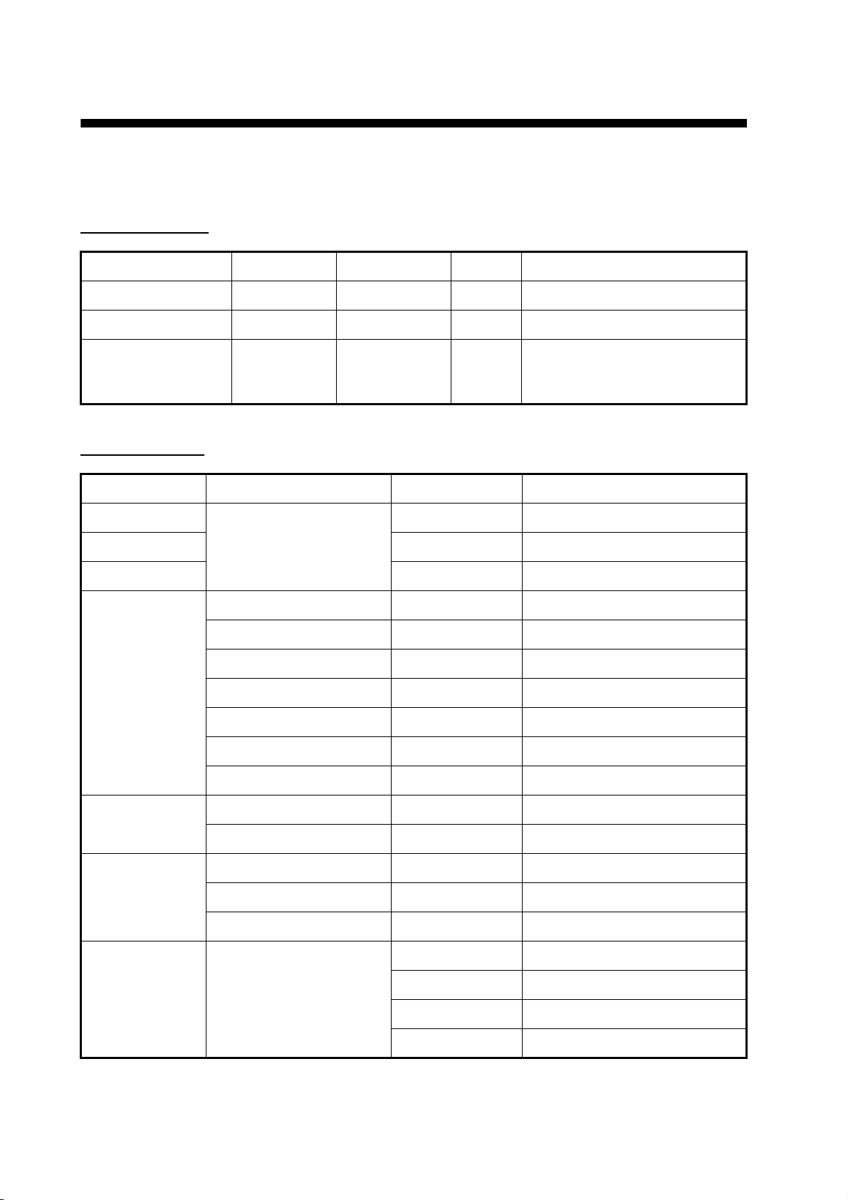
1 GENERAL
1.1 TX frequency 28-200 kHz, two frequencies alternately transmitted (selectable)
1.2 Output power 1/2/3 kW nominal
1.3 Amplifier type Wide dynamic range linear amplifier (double superheterodyne)
1.4 Depth range and Pulse repetition rate (PRR)
200 kHz, TX rate: 20
2 INTERFACE
Range (m) PRR ( /min.)
2 2403 (max)
5 2403
10 1621
40 476
100 222
200 117
400 58
1200 34
DFF3
2.1 Number of port LAN: 1 port, Transducer: 2 port, Temp/speed sensor: 1 port
2.2 Network Ethernet 10BASE-T/100BASE-TX
3 POWER SUPPLY
3.1 Network sounder 12-24 VDC: 2.8-1.4 A
3.2 Rectifier (PR-62, option) 100/110/220/230 VAC, 1 phase, 50/60 Hz
4 ENVIRONMENTAL CONDITION
4.1 Ambient temperature -15°C to +55°C
4.2 Relative humidity 93% at 40°C
4.3 Degree of protection IP20
4.4 Vibration requirement IEC 60945
5 COATING COLOR
N2.5 (not changed)
SP - 1 E2037S01A
080318
Page 31

D-1
28/Mar/08R.Esumi
Page 32

16/Feb/2012 Y.NISHIYAMA
Page 33

FURUNO Worldwide Warranty for Pleasure Boats (Except North America)
This warranty is valid for products manufactured by Furuno
Electric Co. (hereafter FURUNO) and installed on a pleasure
boat. Any web based purchases that are imported into other
countries by anyone other than a FURUNO certified dealer may
not comply with local standards. FURUNO strongly recommends
against importing these products from international websites as
the imported product may not work correctly and may interfere
with other electronic devices. The imported product may also be
in breach of the local laws and mandated technical requirements.
Products imported into other countries as described previously
shall not be eligible for local warranty service.
For products purchased outside of your country please contact
the national distributor of Furuno products in the country where
purchased.
This warranty is in addition to the customer´s statutory legal
rights.
1. Terms and Conditions of Warranty
FURUNO guarantees that each new FURUNO product is the
result of quality materials and workmanship. The warranty is
valid for a period of 2 years (24 months) from the date of the
invoice, or the date of commissioning of the product by the
installing certified dealer.
2. FURUNO Standard Warranty
The FURUNO standard warranty covers spare parts and labour
costs associated with a warranty claim, provided that the product
is returned to a FURUNO national distributor by prepaid carrier.
The FURUNO standard warranty includes:
Repair at a FURUNO national distributor
All spare parts for the repair
Cost for economical shipment to customer
3. FURUNO Onboard Warranty
If the product was installed/commissioned and registered by a
certified FURUNO dealer, the customer has the right to the
onboard warranty.
The FURUNO onboard warranty includes
• Free shipping of the necessary parts
• Labour: Normal working hours only
• Travel time: Up to a maximum of two (2) hours
• Travel distance: Up to a maximum of one hundred
and sixty (160) KM by car for the complete journey
4. Warranty Registration
For the Standard Warranty - presentation of product with serial
number (8 digits serial number, 1234-5678) is sufficient.
Otherwise, the invoice with serial number, name and stamp of
the dealer and date of purchase is shown.
For the Onboard Warranty your FURUNO certified dealer will
take care of all registrations.
5. Warranty Claims
For the Standard Warranty - simply send the defective product
together with the invoice to a FURUNO national distributor.
For the Onboard Warranty – contact a FURUNO national
distributor or a certified dealer. Give the product´s serial number
and describe the problem as accurately as possible.
Warranty repairs carried out by companies/persons other than a
FURUNO national distributor or a certified dealer is not covered
by this warranty.
6. Warranty Limitations
When a claim is made, FURUNO has a right to choose whether
to repair the product or replace it.
The FURUNO warranty is only valid if the product was correctly
installed and used. Therefore, it is necessary for the customer to
comply with the instructions in the handbook. Problems which
result from not complying with the instruction manual are not
covered by the warranty.
FURUNO is not liable for any damage caused to the vessel by
using a FURUNO product.
The following are excluded from this warranty:
a. Second-hand product
b. Underwater unit such as transducer and hull unit
c. Routine maintenance, alignment and calibration
services.
d. Replacement of consumable parts such as fuses,
lamps, recording papers, drive belts, cables, protective
covers and batteries.
d. Magnetron and MIC with more than 1000 transmitting
hours or older than 12 months, whichever comes first.
e. Costs associated with the replacement of a transducer
(e.g. Crane, docking or diver etc.).
f. Sea trial, test and evaluation or other demonstrations.
g. Products repaired or altered by anyone other than the
FURUNO national distributor or an authorized dealer.
h. Products on which the serial number is altered,
defaced or removed.
i. Problems resulting from an accident, negligence,
misuse, improper installation, vandalism or water
penetration.
j. Damage resulting from a force majeure or other natural
k. Damage from shipping or transit.
catastrophe or calamity.
l. Software updates, except when deemed necessary
and warrantable by FURUNO.
m. Overtime, extra labour outside of normal hours such as
weekend/holiday, and travel costs above the 160 KM
allowance
n. Operator familiarization and orientation.
FURUNO Electric Company, March 1, 2011
Page 34

FURUNO Warranty for North America
FURUNO U.S.A., Limited Warranty provides a twenty-four (24) months LABOR and twenty-four (24) months PARTS
warranty on products from the date of installation or purchase by the original owner. Products or components that are
represented as being waterproof are guaranteed to be waterproof only for, and within the limits, of the warranty
period stated above. The warranty start date may not exceed eighteen (18) months from the original date of purchase
by dealer from Furuno USA and applies to new equipment installed and operated in accordance with Furuno USA’s
published instructions.
Magnetrons and Microwave devices will be warranted for a period of 12 months from date of original equipment
installation.
Furuno U.S.A., Inc. warrants each new product to be of sound material and workmanship and through its authorized
dealer will exchange any parts proven to be defective in material or workmanship under normal use at no charge for a
period of 24 months from the date of installation or purchase.
Furuno U.S.A., Inc., through an authorized Furuno dealer will provide labor at no cost to replace defective parts,
exclusive of routine maintenance or normal adjustments, for a period of 24 months from installation date provided the
work is done by Furuno U.S.A., Inc. or an AUTHORIZED Furuno dealer during normal shop hours and within a radius
of 50 miles of the shop location.
A suitable proof of purchase showing date of purchase, or installation certification must be available to Furuno U.S.A.,
Inc., or its authorized dealer at the time of request for warranty service.
This warranty is valid for installation of products manufactured by Furuno Electric Co. (hereafter FURUNO). Any
purchases from brick and mortar or web-based resellers that are imported into other countries by anyone other than a
FURUNO certified dealer, agent or subsidiary may not comply with local standards. FURUNO strongly recommends
against importing these products from international websites or other resellers, as the imported product may not work
correctly and may interfere with other electronic devices. The imported product may also be in breach of the local
laws and mandated technical requirements. Products imported into other countries, as described previously, shall not
be eligible for local warranty service.
For products purchased outside of your country please contact the national distributor of Furuno products in the
country where purchased.
WARRANTY REGISTRATION AND INFORMATION
To register your product for warranty, as well as see the complete warranty guidelines and limitations, please visit
www.furunousa.com
provided through its authorized dealer network. If this is not possible or practical, please contact Furuno U.S.A., Inc.
to arrange warranty service.
and click on “Support”. In order to expedite repairs, warranty service on Furuno equipment is
FURUNO U.S.A., INC.
Attention: Service Coordinator
4400 N.W. Pacific Rim Boulevard
Camas, WA 98607-9408
Telephone: (360) 834-9300
FAX: (360) 834-9400
Furuno U.S.A., Inc. is proud to supply you with the highest quality in Marine Electronics. We know you had several
choices when making your selection of equipment, and from everyone at Furuno we thank you. Furuno takes great
pride in customer service.
Page 35

9-52 Ashihara-cho, Nishinomiya, 662-8580, Japan
Tel: +81 (798) 65-2111 Fax: +81 (798) 65-4200
www.furuno.co.jp
Publication No. DOC-985
EC Declaration of Conformity
We FURUNO ELECTRIC CO., LTD.
-----------------------------------------------------------------------------------------------------------------------------------------------
(Manufacturer)
9-52 Ashihara-Cho, Nishinomiya City, 662-8580, Hyogo, Japan
-----------------------------------------------------------------------------------------------------------------------------------------------
(Address)
declare under our sole responsibility that the product
Network sounder Type DFF3 used in NavNet 3D system
-----------------------------------------------------------------------------------------------------------------------------------------------
(Model name, type number)
to which this declaration relates is in conformity with the following standard(s) or other normative
document(s)
IEC 60945 Fourth edition: 2002-08 – Clauses 9.2, 9.3, 10.3, 10.4, 10.5, 10.8 and 10.9
-----------------------------------------------------------------------------------------------------------------------------------------------
(title and/or number and date of issue of the standard(s) or other normative document(s))
For assessment, see
• EMC Test Report FLI 12-08-007 of 18 February 2008 prepared by Furuno Labotech
International Co., Ltd.
This declaration is issued according to the Directive 2004/108/EC of the European Parliament and of
the Council of 15 December 2004 on the approximation of the laws of the Member States relating to
electromagnetic compatibility and repealing Directive 89/336/EEC
Nishinomiya City, Japan
February 26, 2008
------------------------------------------------------
(Place and date of issue)
On behalf of Furuno Electric Co., Ltd.
Hiroaki Komatsu
Manager,
International Rules and Regulations
----------------------------------------------------------------------------------
(name and signature or equivalent marking of authorized person)
Page 36

9-52 Ashihara-cho,
*
00016858212
**00016858212
*
*
00016858212
**00016858212
*
Nishinomiya, 662-8580, JAPAN
The paper used in this manual
is elemental chlorine free.
・FURUNO Authorized Distributor/Dealer
All rights reserved.
Pub. No. OME-20370-C1
(AKMU ) DFF3
Printed in Japan
A : MAR 2008
C1 : AUG . 03, 2012
* 0 0 0 1 6 8 5 8 2 1 2 *
.
 Loading...