

Page 1

OPERATOR'S MANUAL
NETWORK FISH FINDER
Model
DFF1-UHD
www.furuno.com
Page 2

Page 3
IMPORTANT NOTICES
General
• This manual has been authored with simplified grammar, to meet the needs of international
users.
• The operator of this equipment must read and follow the descriptions in this manual. Wrong
operation or maintenance can cancel the warranty or cause injury.
• Do not copy any part of this manual without written permission from FURUNO.
• If this manual is lost or worn, contact your dealer about replacement.
• The contents of this manual and equipment specifications can change without notice.
• The example screens (or illustrations) shown in this manual can be different from the screens
you see on your display. The screens you see depend on your system configuration and equipment settings.
• Save this manual for future reference.
• Any modification of the equipment (including software) by persons not authorized by FURUNO
will cancel the warranty.
• All brand and product names are trademarks, registered trademarks or service marks of their
respective holders.
How to discard this product
Discard this product according to local regulations for the disposal of industrial waste. For disposal
in the USA, see the homepage of the Electronics Industries Alliance (http://www.eiae.org/) for the
correct method of disposal.
How to discard a used battery
Some FURUNO products have a battery(ies). To see if your product has a battery, see the chapter
on Maintenance. Follow the instructions below if a battery is used. Tape the + and - terminals of
battery before disposal to prevent fire, heat generation caused by short circuit.
In the European Union
The crossed-out trash can symbol indicates that all types of batteries
must not be discarded in standard trash, or at a trash site. Take the
used batteries to a battery collection site according to your national
legislation and the Batteries Directive 2006/66/EU.
In the USA
The Mobius loop symbol (three chasing arrows) indicates that Ni-Cd
and lead-acid rechargeable batteries must be recycled. Take the
used batteries to a battery collection site according to local laws.
In the other countries
Ni-Cd Pb
Cd
There are no international standards for the battery recycle symbol. The number of symbols can
increase when the other countries make their own recycle symbols in the future.
i
Page 4

SAFETY INSTRUCTIONS
The user and installer must read the appropriate safety instructions before attempting to install
or operate the equipment.
Indicates a potentially hazardous situation which, if not avoided,
WARNING
CAUTION
could result in death or serious injury.
Indicates a potentially hazardous situation which, if not avoided,
may result in minor or moderate injury.
Warning, Caution
Safety instructions for the operator
WARNING
Do not open the equipment.
Only qualified personnel should work
inside the equipment.
Do not disassemble or modify the
equipment.
Fire, electrical shock or serious injury can
result.
Turn off the power immediately if the
equipment is emitting smoke or fire.
Fire or electrical shock can result if the
power is left on.
Turn off the power immediately if water
leaks into the equipment or an object is
dropped inside the equipment.
Continued use can cause fire or electrical
shock.
Turn off the power immediately if you
feel the equipment is acting abnormally.
If the equipment is hot to the touch or is
emitting strange noises, turn off the power
immediately and contact your dealer for
advice.
WARNING
Prohibitive Action
Do not operate the equipment with
wet hands.
Electrical shock can result.
Do not place liquid-filled containers
on the top of the equipment.
Electrical shock can result.
Do not install the equipment where
it may be subjected to rain or water
splash.
Fire or electrical shock can result if water
gets inside the equipment.
Use the proper fuse.
Use of a wrong fuse can damage the
equipment and may cause fire.
A warning label is attached to the equipment.
Do not remove this label. If the label is missing
or illegible, contact a FURUNO agent or dealer
about replacement.
Mandatory Action
WARNING
Name: Warning Label (1)
Type: 86-003-1011-3
Code No.: 100-236-233-10
ii
Page 5
CAUTION
Safety instructions for the installer
SAFETY INSTRUCTIONS
WARNING
Do not open the equipment.
Only qualified personnel should work
inside the equipment.
Turn off the power before beginning
the installation.
Fire or electrical shock can result if the
power is left on.
Be sure no water leaks at the mounting
location for the transducer and temperature sensor.
Water leakage can sink the vessel. Also,
confirm that neither the transducer nor
the sensor will loosen by vibration. The
installer is solely responsible for the
installation.
Confirm that the power supply voltage
is within the rating of this equipment.
WARNING
CAUTION
The transducer cable must be handled
carefully, following the guidelines
below.
• Keep fuels and oils away from the
cable.
• Locate the cable away from chemicals.
• Locate the cable away from locations
where it might be damaged.
Do not apply the power with the
transducer exposed to air.
The transducer may be damaged.
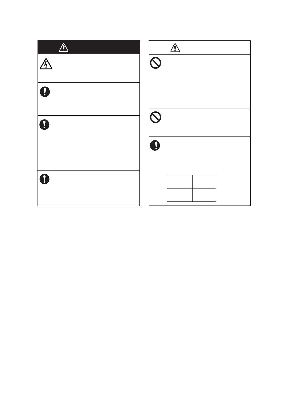
A magnetic compass may receive interference if it is placed too close to the
network fish finder. Observe the compass safe distances shown below to
prevent interference to a magnetic
compass.
Standard
compass
Steering
compass
Incorrect voltage will damage the equipment and may cause fire.
1.00 m 0.60 m
iii
Page 6

TABLE OF CONTENTS
FOREWORD ....................................................................................................................v
SYSTEM CONFIGURATION ..........................................................................................vi
1. INSTALLATION ........................................................................................................1
1.1 Equipment Lists............................................................................................................. 1
1.2 Network Fish Finder ...................................................................................................... 2
1.3 Transducer .................................................................................................................... 3
1.4 Optional Speed/Temperature Sensors ST-02MSB, ST-02PSB.................................... 3
1.4.1 Mounting considerations........................................................................................ 3
1.4.2 Mounting procedure............................................................................................... 3
1.5 Optional Temperature Sensors..................................................................................... 4
1.5.1 Transom mount temperature sensor T-02MTB ..................................................... 4
1.5.2 Thru-hull temperature sensor T-02MSB, T-03MSB............................................... 5
2. WIRING .....................................................................................................................6
2.1 Wiring Outline................................................................................................................ 6
2.2 Transducer Cable, Cable for External KP (option)........................................................ 7
2.2.1 How to process the cables..................................................................................... 7
2.2.2 How to connect the transducer cable .................................................................... 9
2.2.3 How to connect the cable for external KP, transducer cable............................... 11
2.3 LAN Cable................................................................................................................... 17
3. INITIAL SETTINGS .................................................................................................19
3.1 DIP Switch Setting ...................................................................................................... 19
3.2 Operation Check ......................................................................................................... 20
4. MAINTENANCE ......................................................................................................21
4.1 Maintenance................................................................................................................ 21
4.2 How to Replace the Fuse............................................................................................ 22
4.3 How to Restore Default Settings ................................................................................. 22
APPENDIX 1 JIS CABLE GUIDE ..............................................................................AP-1
SPECIFICATIONS .....................................................................................................SP-1
PACKING LIST ............................................................................................................A-1
OUTLINE DRAWINGS................................................................................................. D-1
INTERCONNECTION DIAGRAM ................................................................................ S-1
iv
Page 7

FOREWORD
A Word to the Owner of the DFF1-UHD
Congratulations on your choice of the FURUNO DFF1-UHD Network Fish Finder. We are confident you will see why the FURUNO name has become synonymous with quality and reliability.
Since 1948, FURUNO Electric Company has enjoyed an enviable reputation for quality marine
electronics equipment. This dedication to excellence is furthered by our extensive global network
of agents and dealers.
This equipment is designed and constructed to meet the rigorous demands of the marine environment. However, no machine can perform its intended function unless operated and maintained
properly. Please carefully read and follow the recommended procedures for operation and maintenance.
Thank you for considering and purchasing FURUNO.
Features
The DFF1-UHD is a dual frequency echo sounder designed for use with the NavNet TZtouch series. The DFF1-UHD feeds data about underwater conditions via a LAN.
• FURUNO TruEcho CHIRPTM fishfinders provide very high definition images.
• High resolution display greatly reduces the possibility of missing a target.
• Noise-suppressing display for enhanced detection performance.
• Fish size shown for depths up to 200 m and bottom discrimination.
Operating notices
• Echoes are shown in high ultra definition, thus echoes are displayed differently from those presented on the conventional fish finder.
• The interference rejector operates differently from the interference rejector on the conventional fish
finder, thus its effect on echoes is different.
• The transducer cannot be installed inside the vessel.
TM
• The length of the TX pulse changes according to the state of the ACCU-FISH
the appearance of the display changes with the gain setting.
• Observe the following when using the bottom discrimination display (hereafter referred to as BDD):
• Use the BDD under the following conditions:
- Depth: 5-200 m (16.4-656.2 ft)
- Speed: 10 knots or less
• The BDD uses depth measured from the vessel’s draft in its analysis of bottom composition. Be
sure to set the draft at the NavNet equipment.
• The TX interval slows when the BDD is active.
• The BDD is inoperative if the transducer selection setting at the NavNet TZtouch is “Manual.”
feature. Therefore,
Measure for reduction of interference
If you receive interference from the fish finder/echo sounder of another vessel, switch to single frequency operation and change the frequency and/or reduce the transmitting sound pressure level to
remove the interference.
v
Page 8
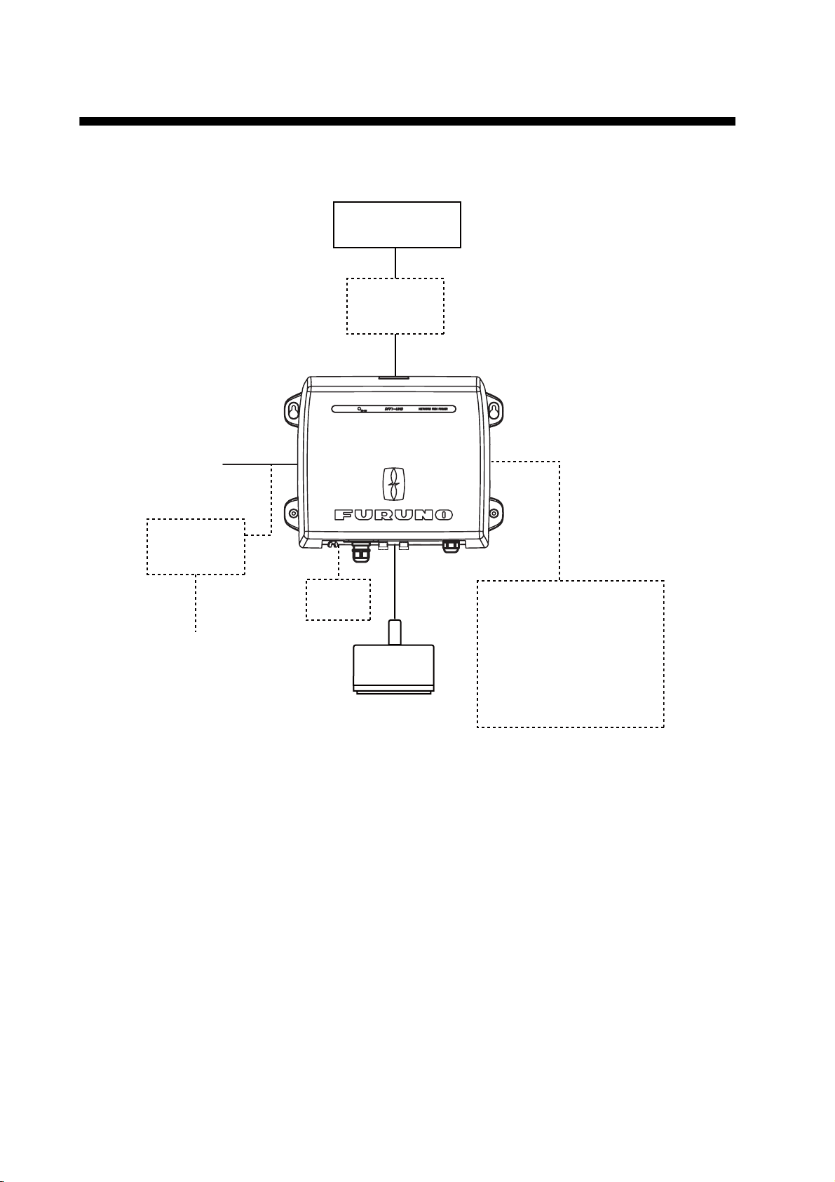
SYSTEM CONFIGURATION
NavNet Equipment
TZT9/14/BB
Ethernet HUB
HUB-101
NETWORK FISH FINDER
DFF1-UHD
12-24 VDC
Rectifier
PR-62
100/110/
220/230 VAC
1ø, 50/60 Hz
External
KP
Transducer
B265LH or
CM265 LH
Speed/Temperature Sensor
ST-02MSB
ST-02PSB
Temperature Sensor
T-02MTB
T-02MSB
T-03MSB
vi
Page 9
1. INSTALLATION
1.1 Equipment Lists
Standard supply
Name Type Code No. Qty Remarks
Network Fish Finder DFF1-UHD — 1
Spare Parts SP02-05601 001-033-740 1 set Fuse (2 pcs.)
Installation Materials CP02-08500 000-011-917 1 set - Power cable assy. (3.5 m)
- LAN cable assy. (5 m)
- Self-tapping screws
Optional supply
Name Type Code No. Remarks
Transducer B265LH 000-022-521 1 kW, bronze housing, thru hull
Transducer CM265LH 000-022-531 1 kW, plastic housing, tank mount
Thru-hull pipe TFB-7000 000-022-532
Tank T-711 000-022-539
Cable Assembly MOD-Z072-020+ 001-167-880-10 2 m, for HUB-101
Cable Assembly MOD-Z072-100+ 001-167-900-10 10 m, for HUB-101
Speed/Temperature Sensor
Temperature
Sensor
Rectifier PR-62 000-013-484 100 VAC
ST-02MSB 001-164-150-10 Thru-hull mount, steel hull
ST-02PSB 001-164-160-10 Thru-hull mount, plastic hull
T-02MTB 000-040-026 Transom mount
T-02MSB 000-040-040 Thru-hull mount
T-03MSB 000-040-027 Thru-hull mount
000-013-485 110 VAC
000-013-486 220 VAC
000-013-487 230 VAC
Connector Kit
for TX Sync
OP02-86 001-205-780
1
Page 10

1. INSTALLATION
1.2 Network Fish Finder
The network fish finder can be installed on a desktop, deck or on a bulkhead. When selecting a
mounting location, keep the following points in mind:
• The temperature and humidity at the mounting site should be moderate and stable.
• The mounting location must satisfy these requirements to get proper performance.
- Operating temperature range: -15 to 55°C (-27 to 99°F)
- Waterproofing standard: IP22
• Locate the unit away from exhaust pipes and vents.
• The mounting location should be well ventilated.
• Mount the unit where shock and vibration are minimal.
• Keep the unit away from electromagnetic field-generating equipment such as motors and generators.
• Leave slack in cables for maintenance and servicing ease.
• A magnetic compass will be affected if the network sounder is placed too close to it. Observe
the compass safe distances noted in the safety instructions to prevent interference to the magnetic compass.
Fasten the network sounder to the mounting location with four self-tapping screws (5×20), referring to the outline drawing at the back of this manual for mounting dimensions.
Note: For mounting on a bulkhead, the connectors must face downward to prevent the possibility
of water leakage into the unit.
2
Page 11
1. INSTALLATION
1.3 Transducer
The performance of the fish finder largely depends upon the transducer position. Select a place
least affected by air bubbles since turbulence blocks the sounding path. The face of the transducer
must be facing the sea bottom in normal cruising trim of the boat. Further, select a place least influenced by engine noise. It is known that air bubbles are fewest at the place where the bow first
falls and the next wave rises, at usual cruising speed.
Do not install the transducer inside the hull. Performance cannot be guaranteed.
1.4 Optional Speed/Temperature Sensors ST-02MSB, ST-02PSB
1.4.1 Mounting considerations
• Select a mid-boat flat position. The sensor does not have to be installed perfectly perpendicular.
However, the sensor must not be located where it may be damaged in dry-docking operations.
• Select a place apart from equipment generating heat.
• Select a place in the forward direction viewing from the drain hole, to allow for circulation of cool-
ing water.
• Select a place free from vibration.
• Do not install near the transducer of an echo sounder, to prevent interference to the echo
sounder.
1.4.2 Mounting procedure
1. Dry dock the boat.
2. Make a hole of approx. 51 mm in diameter in
the mounting location.
3. Unfasten locknut and remove the sensor
section.
4. Apply high-grade sealant to the flange of the
sensor.
5. Pass the sensor casing through the hole.
6. Face the notch on the sensor toward boat's
bow and tighten the flange.
Face "notch"
toward bow.
Flange nut
51
Locknut
123
7. Set the sensor section to the sensor casing
and tighten the locknut.
8. Launch the boat and check for water leakage
around the sensor.
Coat with
silicone sealant.
3
Brim
ø77
Page 12
1. INSTALLATION
1.5 Optional Temperature Sensors
1.5.1 Transom mount temperature sensor T-02MTB
• Fix the cable at a convenient location with cable clamp.
• When the cable is led in through the transom board, make a hole of approx. 17 mm in diameter
to pass the connector. After passing the cable, fill the hole with a sealing compound.
D>50cm
D
5x20
Mount sensor
flush with hull bottom.
4
Page 13

1. INSTALLATION
1.5.2 Thru-hull temperature sensor T-02MSB, T-03MSB
Select a suitable mounting location considering the following points.
• Select a mid-boat flat position. The sensor does not have to be installed perfectly perpendicular.
However, the location should not be such that the transducer may be damaged when the boat
is dry-docked.
• Locate away from equipment which gives off heat.
• Locate away from drain pipes.
• Select a location where vibration is minimal.
T-02MSB T-03MSB
Sensor Holder
Sensor
cable
Sensor
cable
8 m
Locknut
Locknut
Washer
Gasket
Locknut
8 m
21 mm
M20
70 mm
ø42 mm
Mounting procedure
1. Drill a hole of 21 mm in diameter in
the mounting location.
2. Pass the sensor cable through the
hole.
3. Pass gasket, washer and locknut
onto cable in that order.
4. Coat the sensor flange with high
quality sealant and then fasten the
sensor with the locknut.
(Torque: max. 59N·m)
5. Launch the boat to check for water
leakage around the sensor.
Coat with
sealant.
Washer
Gasket
ø25 mm
70 mm
ø50 mm
Holder Guide
Mounting procedure
1. Drill a hole of 25 mm in diameter in the mounting
location.
2. Coat holder guide with high quality sealant, and
pass gasket, washer and locknut onto holder
guide in that order and then tighten the locknut.
3. Set the sensor holder to the holder guide from
inside the boat and then tighten the locknut.
4. Launch the boat to check for water leakage
around the sensor.
M24
Coat with
sealant.
Plate thickness within
25 mm
5
Page 14

2. WIRING
2.1 Wiring Outline
Connect the power cable, transducer cables, sensor cable, network cable and ground wire to their
respective locations on the network sounder. See the next page for how to connect the transducer
cables.
TZT9/TZT14/
TZTBB
To HUB-101
Ground wire
(IV-2 sq)
MOD-Z072-050+, 5 m
(option: 2/10 m)
MJ-A3SPF0013-035C
(3.5 m)
GROUND
Black
BATTERY
12 - 24 VDC
12-24 VDC
2.8-1.4 A
TEMP
Temperature or
Speed/Temperature
Sensor*
White
Shield (green)
DFF1-UHD
EXT-KP TRANSDUCER
External
KP
Transducer
* For no connection,
cover connector
with supplied cap.
Ground
Connect a ground wire (IV-2 sq, local supply) between the
ground terminal and ship’s ground to prevent interference to
the sounder picture. Make the length of the wire as short as
possible. For FRP vessels, install a ground plate that measures about 20 cm by 30 cm on the outside of the hull bottom
and connect the ground wire there.
6
CAUTION
Ground the equipment
to prevent mutual
interference.
Page 15

2. WIRING
2.2 Transducer Cable, Cable for External KP (option)
If the external KP is not to be connected, do only the applicable procedures in sections 2.2.1 and
2.2.2.
The KP from an echo sounder or sonar can be connected to this network fish finder to synchronize
transmission (to prevent interference). Use the optional Connector Kit for TX Sync (Type, OP0286, Code No. 001-205-780) and cable MPYC-4 (or MPYC-2) for the connection. (The MPYC-4 is
a Japan Industrial Standard (JIS) cable. If not available locally, see the Appendix 2 for the equivalent cable.)
Connector kit for TX sync
Name Type Code No. Qty
Upset UI Screw-B M4×20 000-163-756-10 2
Super Gland MGB20M-12B 000-177-248-10 1
PH Connector Assembly 02-1097 (4P) 001-206-000 1
Cable Clamping Plate 02-167-1528 100-379-090-10 1
Rainproofing Panel KP 02-167-1529 100-379-100-10 1
EMI Core GRFC-10 000-177-010-10 1
Crimp-on Lug NCW-1.25 000-157-213-10 4
2.2.1 How to process the cables
Note: The label on the transducer cable can be removed if it interferes with treatment of the cable.
How to process the transducer cable
CM265LH
Sheath
B265LH
Approx. 100
Braided shield
6
Extract cores from here and cut inclusion.
Taping
20
Extract braided shield and wrap it around sheath.
(This part lies in cable clamp.)
Approx. 100
㪍
Put unused wires (3)
in vinyl tubing (local
supply) for insulation.
Wind shield around cable.
(This part lies in cable clamp.)
20
Extract cores from here and
cut inner materials.
Vinyl tape (one turn)
7
Page 16

2. WIRING
A
How to process the cable for the external KP
1. Process the PH connector (02-1097, optional supply) as shown below.
a) Make the length of the wires of the PH connector 100 mm.
b) Remove the sheath from the cores 10 mm.
c) Fold back the cores in half.
d) Attach crimp-on lug NCW-1.25 to each core.
(a)
Approx. 100 mm
(c) (d)
Fold back core.
(b)
Approx. 10 mm
2. Remove the armor 170 mm and cut off the vinyl sheath 90 mm.
MPYC-4
rmor
Vinyl sheath
Approx. 210 mm
Approx. 90 mm
3. Remove 5 mm of the vinyl sheath from the cores then connect each crimp-on lug (attached at
step 2) as shown below.
Approx. 5 mm
4. Wrap the armor with vinyl tape.
Armor
Tape here.
This part is fixed
with the lock nut
inside the unit.
Vinyl sheath
This part is fixed
with the cable
clamp.
Crimp-on lug
NCW-1.25
8
Page 17

2. WIRING
2.2.2 How to connect the transducer cable
This procedure shows you how to connect the transducer cable. To connect both the transducer
cable and the cable for external KP, go to section 2.2.3.
1. Open the cover: Grasp the cover at two sides, spread the cover slightly and lift.
2. Loosen five screws to remove the shield cover.
3. Detach the two WAGO connectors (TB3, TB4) inside the equipment.
TB3
TB4
WAGO connector
Clamp fixing plate
WAGO connector
opener
4. Unfasten the sealing nut from the super gland for the transducer cable.
Sealing nut
9
Page 18

2. WIRING
5. Loosen the two screws fixing the clamp fixing plate to detach the plate.
Clamp fixing plate
6. Pass the sealing nut (unfastened at step 4) onto the transducer cable and pass the cable
through the super gland and into the unit.
7. Use the WAGO connector opener, attached inside the equipment, to connect the transducer
cable to the WAGO connectors, following the instructions in the figure below and the interconnection diagram.
Push
WAGO connector opener
1. Twist conductors.
2. Insert opener as directed and press it down.
Twist.
Core
3. Insert core to hole.
4. Release opener.
5. Pull the core to make sure it is correctly inserted.
8. Attach the WAGO connectors.
9. Refasten the clamp fixing plate, referring to the table below for how to orient the plate.
Transducer type Clamp fixing plate orientation
CM265LH Projection on plate upward
B265LH Projection on plate downward
10
Page 19

2. WIRING
10. Tighten the sealing nut according to the information in the table below.
Transducer Clearance Torque
CM265LH 4 mm 1.8 - 2.0N/m
B265LH 2 mm
Clearance
11. Reattach the shield cover and close the outer cover.
2.2.3 How to connect the transducer cable, cable for external KP
1. Remove the cover, shield cover and WAGO connectors, referring to steps 1-3 in section 2.2.2.
2. Unfasten the lock nut of the inside the unit to detach the super gland.
Clamp fixing plate
Clamp
Lock nut
Super gland
3. Unfasten two screws to remove the clamp fixing plate.
4. Unfasten two screws securing the clamp. Save the screws for later use.
5. Unfasten the four screws securing the rainproofing panel. You may discard the panel. Save
the screws for later use.
11
Page 20

2. WIRING
6. Unfasten the nut material inside the unit.
Clamp fixing
plate
Clamp
Nut material
Rainproofing
panel
7. Using the two screws removed at step 5, fasten the upper two holes of the supplied rainproofing panel.
Fasten upper two holes
Rainproofing panel (supplied)
12
Page 21

2. WIRING
8. TIghten the lock nut inside the unit to fasten the super glands (two pcs., see step 12). The
torque for the lock nut shall be 1.8 - 2.0 N/m.
Super gland (two pcs.)
9. Set the nut material (removed at step 6) inside the unit, align its two protrusions with the lower
holes on the rainproofing panel. Use the remaining two screws removed at step 5 to fasten
the lower two holes on the rainproofing panel.
Fasten lower two holes
10. Use two screws to fasten the clamp removed at step 4.
13
Page 22

2. WIRING
11. For the transducer cable and the cable for the external KP, pass each cable through its
super gland, the supplied rainproofing panel and each hole in the unit. Then slip a lock nut
onto each cable. (For the super gland of the cable for the external KP, unfasten the lock nut
from the super gland then pass the cable through the super gland. See page 8 for how to treat
the cable end.)
Lock nut
Cable for
Ext. KP
(MPYC-4)
Super gland
Sealing nut
Rainproofing panel
After passing the cable for the external KP, do as follows:
- Assemble the super gland.
- Tighten the sealing nut until the clearance is 4 mm. The torque shall be 1.8 - 2.0N/m.
4 mm
14
Page 23

2. WIRING
12. Transducer cable: Lay the transducer cable in the cable clamp then refasten the clamp fixing
plate.
Cable for the external KP: Lay the cable in the cable clamp and fix it with the supplied clamp
fixing plate and two upset screws.
Lock nut for super gland (2 pcs.)
Clamp fixing plate
Large: transducer cable
Small: cable for external KP
13. Connect the cables as follows:
• Transducer cable: See section 2.2.2.
• Cable for external KP: See the illustration below. Pass the cable through the edge saddle
and connect the cable to J12 on the PWRTX board. Be sure the cable does not contact TB4.
J12
Be sure cable does
Edge saddle
not contact TB4.
Lay vinyl sheath in
cable clamp and
fasten clamp fixing
plate (supplied).
(See step 11.)
Note: For cable MPYC-2, tape the vinyl sheath of the cable (approx. 6 to 7 turns) where it lies
in the cable clamp and fasten the cable clamp. The PH connector has two unused harnesses.
Cut them at their base or wrap them with vinyl tape.
15
Cut off two unused
harnesses at base.
Taping.
Page 24

2. WIRING
14. Attach the supplied EMI core (GRFC-10) to the cable for the external KP approx. 100 mm from
the super gland.
10 mm
15. Attach the shield cover and close the outer cover.
Super gland
(for ext. KP)
EMI core
16
Page 25

2. WIRING
2.3 LAN Cable
Do as follows to connect the supplied LAN cable (MOD-Z072-050+) or the optional LAN cable
(MOD-Z072-020+, MOD-Z072-100+).
1. Unfasten the sealing nut from the LAN connector then remove the sealing insert and clamping
claw.
2. Detach the sealing insert from the clamping claw as shown below.
Seal assy.
Super
gland
Sealing insert
Insert seal
Clamping claw
Sealing nut
How to detach clamping claw
Push in the sealing insert
with your thumbs.
Hold the clamping
claw/seal assy. as shown
left, with the teeth of
the clamping claw toward
you.
17
Page 26

2. WIRING
3. Pass the sealing nut, clamping claw and sealing insert onto the LAN cable in the order shown
in the figure below. Connect the cable to the LAN connector. (Note the orientation of the sealing insert when passing it onto the cable. Push the cable into the slit in the sealing insert.)
LAN cable
Sealing insert
(Push cable into slit.)
Clamping claw
Sealing nut
4. Set the sealing insert and clamping claw into the sealing nut then tighten the nut.
5. Tighten the sealing nut to fasten the LAN cable. The clearance between the lock nut and the
sealing nut shall be 3 mm. The torque for the sealing nut shall be 1.8 - 2.0 N/m.
Clearance
How to disconnect the LAN cable
Loosen the two screws on the gland to access the cable’s connector. A lock washer is fitted to the
gland and the screws cannot be unfastened completely.
Screw (2 pcs.)
Gland
18
Page 27

3. INITIAL SETTINGS
WARNING
Do not open the equipment unless totally
familiar with electrical circuits.
Only qualified personnel should work inside
the equipment.
3.1 DIP Switch Setting
The DIP switch S2 sets up the system according to the equipment connected. In the default setting
all switches (1-8) are OFF. The DIP switch S3 should not be adjusted; leave all switches in the
OFF position.
DIP Switches
(factory settings)
S3
4-1
ON
OFF
S2
1-8
ON
OFF
DIP switch S2 description
Switch
No.
1 IP mode OFF: FIxed (static) IP address. Set the IP address
2 IP address no. OFF: Set the #1 switch to OFF to set IP address. See
3 Restore default settings (other than
LAN and transducer)
4 Restore ALL default settings See section 4.3.
5 - 6 Keep these switches in the OFF position.
7 No use
8 No use
Function Setting
with switch #2, referring to the table below.
ON: Use IP address assigned by DHCP.
the table on the next page for IP address assignment.
See section 4.3.
19
Page 28

3. INITIAL SETTINGS
#2 Host name IP address
OFF ES092002 172.031.092.002
ON ES092003 172.031.092.003
After setting up the transducer at the DFF1-UHD, set the transducer type at the NavNet device.
See respective Installation Manual for the procedure.
Note: DIP Switch S2 is for factory use. Do not change the settings.
3.2 Operation Check
For NavNet TZtouch, the DFF1-UHD is powered on/off from ship’s switchboard. For NavNet 3D,
it is powered on/off from the display unit. The LED on the cover of the DFF1-UHD lights or blinks
according to equipment state, as described in the table below.
LED state and meaning
LED state Meaning
Lighting continuously • Standby state. (If no signal is received via LAN for more than 10
minutes, the equipment automatically goes into standby to lessen
power consumption.)
• Power on (20 seconds during initialization)
• IP address not set
Blinking every two seconds Normal operation
Blinking every 0.4 seconds Transducer settings at NavNet device not properly set.
LED
20
Page 29

4. MAINTENANCE
WARNING
ELECTRICAL SHOCK HAZARD
Do not open the equipment.
Only qualified personnel
should work inside the
equipment.
Do not apply paint, anti-corrosive sealant or
contact spray to coating or plastic parts of
the equipment.
Those items contain organic solvents that can
damage coating and plastic parts, especially
plastic connectors.
NOTICE
4.1 Maintenance
Regular maintenance is essential for good performance. Check the items listed in the table below
at the suggested interval to help keep your equipment in good shape for years to come.
Item Check point, action Check interval
Transducer cable Check that cable is tightly fastened and is not
damaged. Refasten if necessary. Replace if
damaged.
Power cable, sensor
cable
Check that these cables are tightly fastened and
not damaged. Refasten if necessary. Replace if
damaged.
Once a month
Once a month
Ground Check for corrosion. Clean if necessary. Once a month
Power supply voltage Check voltage. If out of rating correct problem. Once a month
Cleaning the network
fish finder’s cabinet
Transducer Marine life on the transducer face will result in a
Dust or dirt on the cabinet may be removed with a
dry cloth. Do not use chemical-based cleaners to
clean the cabinet; they can remove markings and
damage the cabinet.
gradual decrease in sensitivity. Check the transducer face for cleanliness each time the boat is
removed from the water. Carefully remove any
marine life with a piece of wood or fine-grade
sandpaper.
Once a month
When vessel is removed from the water
21
Page 30

4. MAINTENANCE
4.2 How to Replace the Fuse
The 5A fuse (Type: FGBO-A 125V 5A PBF, Code No. 000-155-853-10) in the snap-in fuse holder
on the power cable protects the equipment from equipment fault and reverse polarity of the power
supply. If the equipment cannot be powered, the fuse may have blown. Find out the cause for the
blown fuse before replacing it. If the fuse blows again after replacement, contact a FURUNO agent
or dealer for instructions.
WARNING
Use the proper fuse.
Use of a wrong fuse can damage the equipment and cause fire.
4.3 How to Restore Default Settings
This procedure restores all default sounder settings on the NavNet series device. You can restore
all default settings or restore those other than transducer and LAN. This procedure should only be
performed by a suitably qualified FURUNO technician.
1. Disconnect the power and LAN cables from the DFF1-UHD.
2. Turn on the #3 or #4 switch of DIP Switch S3 as applicable.
#3: Restore default settings other than LAN and transducer.
#4: Restore all default settings. Use this when changing transducers.
3. Connect the power cable to the DFF1-UHD, and turn on the power at the ship’s switchboard.
4. The LED blinks (every 0.4 seconds) when default settings are completely restored.
5. Set up the transducer at the NavNet equipment.
22
Page 31

APPENDIX 1 JIS CABLE GUIDE
Cables listed in the manual are usually shown as Japanese Industrial Standard (JIS). Use the following guide to locate an
equivalent cable locally.
JIS cable names may have up to 6 alphabetical characters, followed by a dash and a numerical value (example: DPYC-2.5).
For core types D and T, the numerical designation indicates the cross-sectional Area (mm
2
) of the core wire(s) in the cable.
For core types M and TT, the numerical designation indicates the number of core wires in the cable.
1. Core Type 2. Insulation Type 3. Sheath Type
Double core power line
D
Triple core power line
T
Multi core
M
Twisted pair communications (1Q=quad cable)
TT
4. Armor Type 5. Sheath Type 6. Shielding Type
Steel
C
Y
-SLA
1 2 3 4 5 6 1 2 3 4
Ethylene Propylene Rubber
P
Anticorrosive vinyl sheath
PVC (Vinyl)
Y
SLA
All cores in one shield,
plastic tape w/aluminum tape
Individually shielded cores,
plastic tape w/aluminum tape
DPYCY
TPYCY
MPYC-4
EX: DPYCYSLA - 1.5 MPYC - 4
Designation type
Core Area (mm
2
)
Designation type
# of cores
TTYCSLA-4
The following reference table lists gives the measurements of JIS cables commonly used with Furuno products:
Core Cable Core Cable
Type Area Diameter Type Area Diameter
2
DPYC-1.5 1.5mm
DPYC-2.5 2.5mm
DPYC-4 4.0mm
DPYC-6 6.0mm
DPYC-10 10.0mm
DPYC-16 16.0mm
DPYCY-1.5 1.5mm
DPYCY-2.5 2.5mm
DPYCY-4 4.0mm
DPYCYSLA-1.5 1.5mm
DPYCYSLA-2.5 2.5mm
MPYC-2 1.0mm
MPYC-4 1.0mm
MPYC-7 1.0mm
MPYCY-12 1.0mm
MPYCY-19 1.0mm
1.56mm 11.7mm
2
2.01mm 12.8mm
2
2.55mm 13.9mm
2
3.12mm 15.2mm
2
4.05mm 17.1mm
2
5.10mm 19.4mm
2
1.56mm 13.7mm
2
2.01mm 14.8mm
2
2.55mm 15.9mm
2
1.56mm 11.9mm
2
2.01mm 13.0mm
2
1.29mm 10.0mm
2
1.29mm 11.2mm
2
1.29mm 13.2mm
2
1.29mm 19.0mm
2
1.29mm 22.0mm
Diameter Diameter
2
TPYCY-1.5 1.5mm
TPYCY-2.5 2.5mm
TPYCY-4 4.0mm
TPYCYSLA-1.5 1.5mm
TTYC-7SLA 0.75mm
TTYCSLA-1 0.75mm
TTYCSLA-1Q 0.75mm
TTYCSLA-4 0.75mm
TTYCY-4SLA 0.75mm
TTYCYSLA-1 0.75mm
TTYCYSLA-4 0.75mm
1.56mm 14.5mm
2
2.01mm 15.5mm
2
2.55mm 16.9mm
2
1.56mm 13.9mm
2
1.11mm 20.8mm
2
1.11mm 9.4mm
2
1.11mm 10.8mm
2
1.11mm 15.7mm
2
1.11mm 19.5mm
2
1.11mm 11.2mm
2
1.11mm 17.9mm
AP-1
Page 32

FURUNO
SPECIFICATIONS OF NETWORK FISH FINDER
DFF1-UHD
1 GENERAL
1.1 TX frequency 50/200 kHz, alternative transmission
1.2 Output power 1 kW nominal
1.3 Amplifier type Straight amplifier (H/L gain switching available)
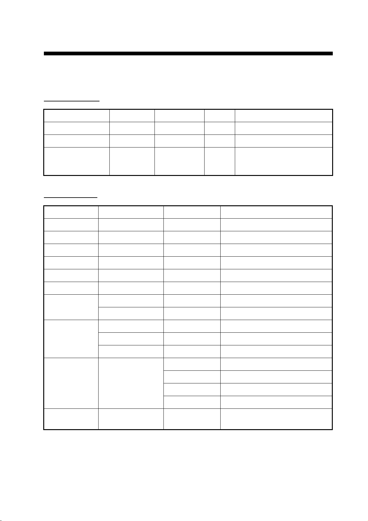
1.4 Depth range and Pulse repetition rate (PRR) at 200 kHz, TX rate: 20
Range (m) PRR (times/min, max.)
2 2403
5 2403
10 1621
40 476
100 222
400 58
1200 34
2 INTERFACE
2.1 I/O port
Network 1 port
Temp/speed sensor 1 port
External KP 1 port (external KP kit: option)
2.2 Network method Ethernet 10Base-T/100Base-TX
3 POWER SUPPLY
3.1 Network fish finder 12-24 VDC: 2.5-1.3 A
3.2 Rectifier (PR-62, option) 100/110/220/230 VAC, 1 phase, 50/60 Hz
4 ENVIRONMENTAL CONDITIONS
4.1 Ambient temperature -15°C to +55°C
4.2 Relative humidity 93% or less at +40°C
4.3 Degree of protection IP22
4.4 Vibration IEC 60945 Ed.4
5 UNIT COLOR
5.1 Network fish finder N2.5 (fixed)
DFF1-UHD
SP - 1 E2040S01A
121203
Page 33

PACKING LIST
A-1
DFF1-UHD
02GL-X-9851 -0
1/1
N A M E
O U T L I N E
DESCRIPTION/CODE №
ユニット UNIT
ネットワーク魚探
NETWORK FISH FINDER
DFF1-UHD
000-022-520-00
予備品 SPARE PARTS SP02-05601
ヒューズ
GLASS TUBE FUSE
FGB0-A 125V 5A PBF
000-155-853-10
工事材料 INSTALLATION MATERIALS CP02-08500
+トラスタッピンネジ 1シュ
SELF-TAPPING SCREW
5X20 SUS304
000-162-608-10
ケーブル(組品)LAN
LAN CABLE ASSEMBLY
MOD-Z072-050+
000-167-176-10
ケーブル組品MJ
CABLE ASSEMBLY
MJ-A3SPF0013-035C(5A)
000-157-939-10
図書 DOCUMENT
取扱説明書
OPERATOR'S MANUAL
OM*-20400-*
000-177-244-1*
Q'TY
1
2
4
1
1
1
**
コ-ド番号末尾の[**]は、選択品の代表コードを表します。
CODE NUMBER ENDING WITH "**" INDICATES THE CODE NUMBER OF REPRESENTATIVE MATERIAL.
型式/コード番号が2段の場合、下段より上段に代わる過渡期品であり、どちらかが入っています。 なお、品質は変わりません。
TWO TYPES AND CODES MAY BE LISTED FOR AN ITEM. THE LOWER PRODUCT MAY BE SHIPPED IN PLACE OF THE UPPER
PRODUCT. QUALITY IS THE SAME.
(略図の寸法は、参考値です。 DIMENSIONS IN DRAWING FOR REFERENCE ONLY.)
02GL-X-9851
Page 34

D-1
7/Dec/2012Y.NISHIYAMA
Page 35

DFF1-UHD
S-1
ネットワーク魚探
相互結線図
NETWORK FISH FINDER
INTERCONNECTION DIAGRAM
イーサネットハブ
ETHERNET HUB
*2
HUB-101
または OR
MULTI FUNCTION DISPLAY
MFD8/12/BB
マルチファンクションディスプレイ
TZT9/14/BB
TITLE
名称
NAME
43
02-167-1001-2C2040-C01- C
REF.No.
MOD-Z072-050+,5m
(2/10m *2)
RJ45 RJ45
8 8
*3
TEMP
J5
NETWORK
DFF1-UHD
NETWORK FISH FINDER
ネットワーク魚探
TRIG_IN_P
TRIG_IN_N
TRIG_OUT_P
123
MPYC-4
KP OUT
TRIG_OUT_N
4
KP IN
J12(PH4P)
1B 2 02P6385
(+)
(-)
SHIELD
SHIELD
TEMP
TEMP_0V
J1
2
123
MJ-A3SPF
WHTシロ
5A
BLK
クロ
GRN
ミドリ
J2
MJ-A6SPF
1
2
8mDPYC-1.5
SPEED
345
*1
12V_P
IV-2sq.
02P63601B 3
GND
6
*2
TEMP/SPEED
水温・船速センサー
SENSOR
ST-02MSB/PSB
T-02MTB/MSB
*2
KP KIT
*1
T-03MSB
TEMP_XID_GND
XID
SHIELD
NC
TB4
XD_LO_P
NC
XD_LO_SHIELD
XD_LO_M
XD_HI_M
XD_HI_SHIELD
NC
XD_HI_P
TB3
5
4
3
2
1
8
7
6
5
4
3
2
1
*1
IV-2sq.
WHT
BRN
ORG
DRAIN
BLU/WHT
DRAIN
BLK/WHT
BLK
DRAIN
BLU
シロ
チャ
ダイ
アオ/シロ
クロ/シロ
クロ
アオ
12m
送受波器
B265LH
TRANSDUCER
CM265LH
DRAWN
T.YAMASAKI
9/Jan/2013
CHECKED
kg
H.MAKI
9/Jan/2013
9/Jan/2013Y.NISHIYAMA
APPROVED
SCALE MASS
DWG.No.
123
(+)
(-)
*2
PR-62
整流器
*1
A
RECTIFIER
5
6
100-115/
220/230VAC,
1φ,50/60Hz
NOTE
*1: SHIPYARD SUPPLY.
注記
*1)造船所手配。
*2)オプション。
*3)CM265LHのみ。
B
C
*2: OPTION.
*3: CM265LH ONLY.
MJ-A3SPF0013-035C,3.5m
1
12-24VDC (+)
(-)
GND
Page 36

FURUNO Worldwide Warranty for Pleasure Boats (Except North America)
This warranty is valid for products manufactured by Furuno
Electric Co. (hereafter FURUNO) and installed on a pleasure
boat. Any web based purchases that are imported into other
countries by anyone other than a FURUNO certified dealer may
not comply with local standards. FURUNO strongly recommends
against importing these products from international websites as
the imported product may not work correctly and may interfere
with other electronic devices. The imported product may also be
in breach of the local laws and mandated technical requirements.
Products imported into other countries as described previously
shall not be eligible for local warranty service.
For products purchased outside of your country please contact
the national distributor of Furuno products in the country where
purchased.
This warranty is in addition to the customer´s statutory legal
rights.
1. Terms and Conditions of Warranty
FURUNO guarantees that each new FURUNO product is the
result of quality materials and workmanship. The warranty is
valid for a period of 2 years (24 months) from the date of the
invoice, or the date of commissioning of the product by the
installing certified dealer.
2. FURUNO Standard Warranty
The FURUNO standard warranty covers spare parts and labour
costs associated with a warranty claim, provided that the product
is returned to a FURUNO national distributor by prepaid carrier.
The FURUNO standard warranty includes:
Repair at a FURUNO national distributor
All spare parts for the repair
Cost for economical shipment to customer
3. FURUNO Onboard Warranty
If the product was installed/commissioned and registered by a
certified FURUNO dealer, the customer has the right to the
onboard warranty.
The FURUNO onboard warranty includes
• Free shipping of the necessary parts
• Labour: Normal working hours only
• Travel time: Up to a maximum of two (2) hours
• Travel distance: Up to a maximum of one hundred
and sixty (160) KM by car for the complete journey
4. Warranty Registration
For the Standard Warranty - presentation of product with serial
number (8 digits serial number, 1234-5678) is sufficient.
Otherwise, the invoice with serial number, name and stamp of
the dealer and date of purchase is shown.
For the Onboard Warranty your FURUNO certified dealer will
take care of all registrations.
5. Warranty Claims
For the Standard Warranty - simply send the defective product
together with the invoice to a FURUNO national distributor.
For the Onboard Warranty – contact a FURUNO national
distributor or a certified dealer. Give the product´s serial number
and describe the problem as accurately as possible.
Warranty repairs carried out by companies/persons other than a
FURUNO national distributor or a certified dealer is not covered
by this warranty.
6. Warranty Limitations
When a claim is made, FURUNO has a right to choose whether
to repair the product or replace it.
The FURUNO warranty is only valid if the product was correctly
installed and used. Therefore, it is necessary for the customer to
comply with the instructions in the handbook. Problems which
result from not complying with the instruction manual are not
covered by the warranty.
FURUNO is not liable for any damage caused to the vessel by
using a FURUNO product.
The following are excluded from this warranty:
a. Second-hand product
b. Underwater unit such as transducer and hull unit
c. Routine maintenance, alignment and calibration
services.
d. Replacement of consumable parts such as fuses,
lamps, recording papers, drive belts, cables, protective
covers and batteries.
e. Magnetron and MIC with more than 1000 transmitting
hours or older than 12 months, whichever comes first.
f. Costs associated with the replacement of a transducer
(e.g. Crane, docking or diver etc.).
g. Sea trial, test and evaluation or other demonstrations.
h. Products repaired or altered by anyone other than the
FURUNO national distributor or an authorized dealer.
i. Products on which the serial number is altered,
defaced or removed.
j. Problems resulting from an accident, negligence,
misuse, improper installation, vandalism or water
penetration.
k. Damage resulting from a force majeure or other natural
catastrophe or calamity.
l. Damage from shipping or transit.
m. Software updates, except when deemed necessary
and warrantable by FURUNO.
n. Overtime, extra labour outside of normal hours such as
weekend/holiday, and travel costs above the 160 KM
allowance
o. Operator familiarization and orientation.
FURUNO Electric Company, March 1, 2011
Page 37

FURUNO Warranty for North America
FURUNO U.S.A., Limited Warranty provides a twenty-four (24) months LABOR and twenty-four (24) months PARTS
warranty on products from the date of installation or purchase by the original owner. Products or components that are
represented as being waterproof are guaranteed to be waterproof only for, and within the limits, of the warranty
period stated above. The warranty start date may not exceed eighteen (18) months from the original date of purchase
by dealer from Furuno USA and applies to new equipment installed and operated in accordance with Furuno USA’s
published instructions.
Magnetrons and Microwave devices will be warranted for a period of 12 months from date of original equipment
installation.
Furuno U.S.A., Inc. warrants each new product to be of sound material and workmanship and through its authorized
dealer will exchange any parts proven to be defective in material or workmanship under normal use at no charge for a
period of 24 months from the date of installation or purchase.
Furuno U.S.A., Inc., through an authorized Furuno dealer will provide labor at no cost to replace defective parts,
exclusive of routine maintenance or normal adjustments, for a period of 24 months from installation date provided the
work is done by Furuno U.S.A., Inc. or an AUTHORIZED Furuno dealer during normal shop hours and within a radius
of 50 miles of the shop location.
A suitable proof of purchase showing date of purchase, or installation certification must be available to Furuno U.S.A.,
Inc., or its authorized dealer at the time of request for warranty service.
This warranty is valid for installation of products manufactured by Furuno Electric Co. (hereafter FURUNO). Any
purchases from brick and mortar or web-based resellers that are imported into other countries by anyone other than a
FURUNO certified dealer, agent or subsidiary may not comply with local standards. FURUNO strongly recommends
against importing these products from international websites or other resellers, as the imported product may not work
correctly and may interfere with other electronic devices. The imported product may also be in breach of the local
laws and mandated technical requirements. Products imported into other countries, as described previously, shall not
be eligible for local warranty service.
For products purchased outside of your country please contact the national distributor of Furuno products in the
country where purchased.
WARRANTY REGISTRATION AND INFORMATION
To register your product for warranty, as well as see the complete warranty guidelines and limitations, please visit
www.furunousa.com
provided through its authorized dealer network. If this is not possible or practical, please contact Furuno U.S.A., Inc.
to arrange warranty service.
and click on “Support”. In order to expedite repairs, warranty service on Furuno equipment is
FURUNO U.S.A., INC.
Attention: Service Coordinator
4400 N.W. Pacific Rim Boulevard
Camas, WA 98607-9408
Telephone: (360) 834-9300
FAX: (360) 834-9400
Furuno U.S.A., Inc. is proud to supply you with the highest quality in Marine Electronics. We know you had several
choices when making your selection of equipment, and from everyone at Furuno we thank you. Furuno takes great
pride in customer service.
Page 38

Page 39

Page 40

9-52, Ashihara-cho,
Nishinomiya, 662-8580, JAPAN
(Elemental Chlorine Free)
The paper used in this manual
is
elemental chlorine free.
FURUNO Authorized Distributor/Dealer
All rights reserved.
Printed in Japan
Pub. No. OME-20400-B
(DAMI) DFF1-UHD
A: JAN. 2013
B: JAN. 31, 2013
 Loading...