

Page 1

MEMORY CARD INTERFACE UNIT
CU-300
www.furuno.co.jp
Page 2

Page 3
SAFETY INSTRUCTIONS
The user and installer must read the appropriate safety instructions before attempting to install
or operate the equipment.
Indicates a potentially hazardous situation which, if not avoided,
WARNING
CAUTION
Warning, Caution
Safety instructions for the operator
could result in death or serious injury.
Indicates a potentially hazardous situation which, if not avoided,
may result in minor or moderate injury.
Prohibitive Action
Mandatory Action
WARNING
Do not open the equipment.
Only qualified personnel should work
inside the equipment.
Immediately turn off the power at the
switchboard if water leaks into the
equipment or something is dropped
into the equipment.
Continued use of the equipment can cause
fire or electrical shock. Contact a FURUNO
agent for service.
Immediately turn off the power at the
switchboard if the equipment is emitting
smoke or fire.
Continued use of the equipment can cause
fire or electrical shock. Contact a FURUNO
agent for service.
Do not disassemble or modify the
equipment.
Fire, electrical shock or serious injury can
result.
WARNING
Do not place liquid-filled containers on
the top of the equipment.
Fire or electrical shock can result if a liquid
spills into the equipment.
Do not operate the equipment with
wet hands.
Electrical shock can result.
Turn off the power immediately
if you feel the equipment is behaving
abnormally.
Turn off the power at the switchboard if
the equipment becomes abnormally warm
or is emitting odd noises. Contact a
FURUNO dealer or agent for advice.
Make sure no rain or water splash leaks
into the equipment.
Fire or electrical shock can result if water
leaks in the equipment.
i
Page 4
WARNING
CAUTION
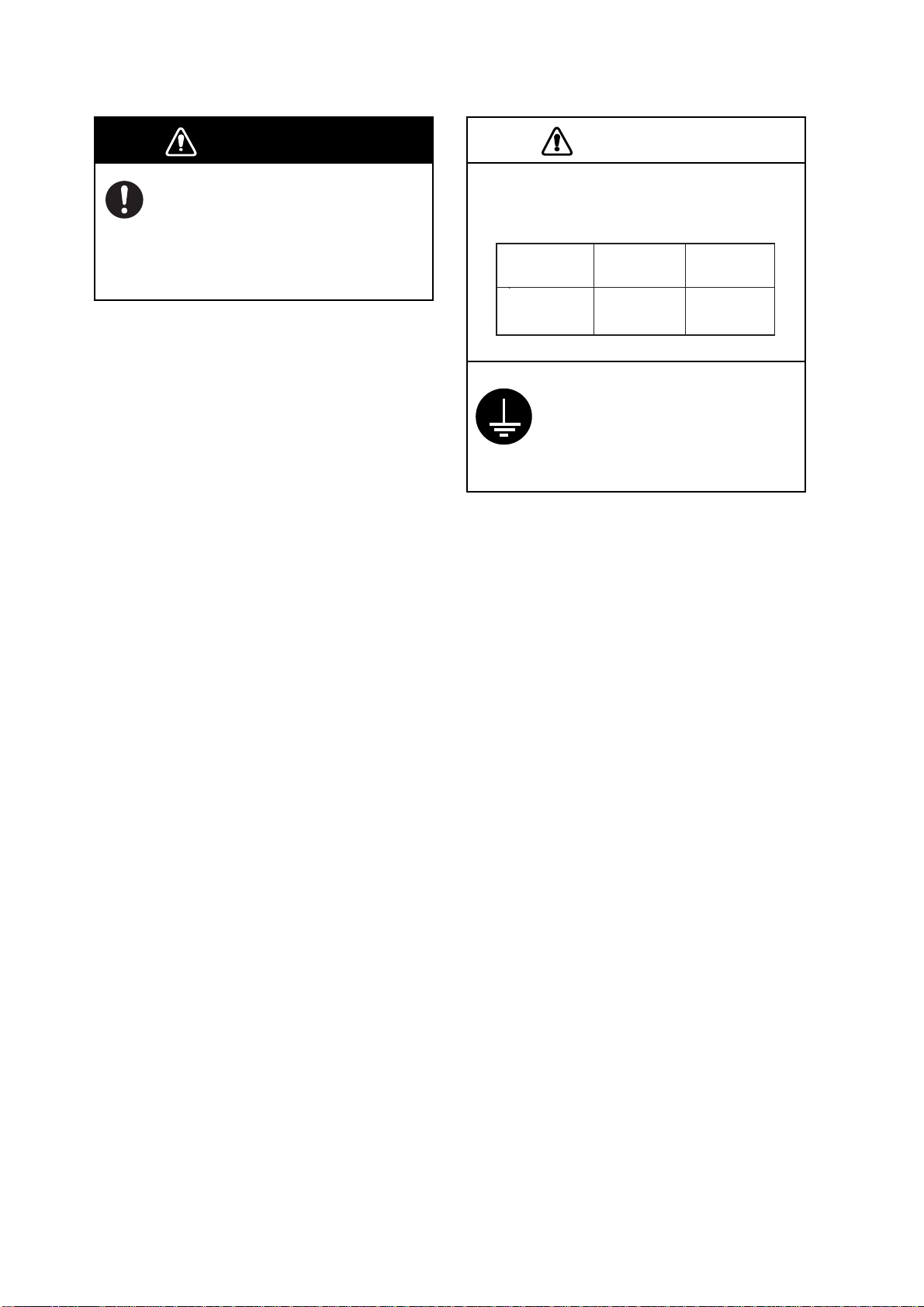
Turn off the power at the
switchboard before beginning the
installation.
Fire or electrical shock can result if
the power is left on.
Observe the following compass safe
distances to prevent interference to a
magnetic compass:
Standard
compass
CU-300
Attach grounding securely
to ship's body.
The grounding is required
to prevent electrical shock.
Steering
compass
0.45 m0.70 m
ii
Page 5

TABLE OF CONTENTS
SYSTEM CONFIGURATIONS....................................................................iv
EQUIPMENT LISTS....................................................................................vi
1. MOUNTING............................................................................................1
1.1 Flush Mounting................................... ................................. .................. ................... ....1
1.2 Desktop Mounting......... .... ................................. .................. .................. ................... ....2
1.3 Overhead Mounting................. .... ................................. .................. .................. ............3
2. WIRING..................................................................................................5
2.1 Connection between One Processor Unit and One Memory Card Interface Unit ........5
2.2 Con nection bet w een One Me m ory C ard Interfa c e U nit and Multi ple Process or U nits
(Max. Three Units)........................................................................................................6
2.3 Con nection bet w een Two Memory Car d I nt erf ace Units and Two Proc essor Units.....7
3. OPERATION..........................................................................................9
3.1 Basic Operation.................................. ................................. .................. ................... ....9
3.2 Priority of Card Drives ................................................................................................ 10
SPECIFICATION....................................................................................SP-1
PACKING LISTS......................................................................................A-1
OUTLINE DRAWINGS............................................................................. D-1
iii
Page 6

SYSTEM CONFIGURATIONS
The Memory Card Interface Unit CU-300 connects to a processor unit of MODEL18x4C-BB/
19x4C-BB or GD-1920C-BB (NavNet VX2-BB) to provide a card drive(s) in a remote location(s).
Power to the CU-300 is supplied from the processor unit. Maximum four units can be connected
via a HUB. Note that th e CU- 300 can b e conne cte d only to th e NavNe t V X2 uni ts which have the
followin g s of t w are version N o.
C-MAP specification
Type Version No.
MODEL 18x4C-BB/19x4C-BB, GD-1920C-BB 1950026-02.01 and after
MODEL 18x4C/19x4C, GD-1920C 1950024-02.01 and after
MODEL 17x4C, GD-1720C 1950028-02.01 and after
NAVIONICS spe c ifi ca t ion
Type Version No.
MODEL 18x4C-BB/19x4C-BB, GD-1920C-BB 1950025-01.09 and after
MODEL 18x4C/19x4C, GD-1920C 1950023-01.09 and after
MODEL 17x4C, GD-1720C 1950027-01.09 and after
iv
Page 7
Connection to single NavNet VX2-BB unit
Power cable
CU-300
MJ-A3SPF0026-050C or 100C
Ethernet cable
MJ-A6SPF0017-050C or 100C
Connection to multiple NavNet VX2-BB units
CU-300
Power cable
MJ-A3SPF0026-050C or 100C
Model 18x4C-BB/19x4C-BB
GD-1920C-BB
Model 18x4C-BB/19x4C-BB
GD-1920C-BB
LAN cable (CAT5,
STP, straight)
HUB
Model 18x4C-BB/19x4C-BB, GD-1920C-BB,
Model 18x4C/19x4C, GD-1920C
Model 17x4C or GD-1720C
Model 18x4C-BB/19x4C-BB, GD-1920C-BB,
Model 18x4C/19x4C, GD-1920C
Model 17x4C or GD-1720C
: Standard supply
: Local supply
: NavNet VX2
: Option for NavNet VX2
v
Page 8
Connection for two CU-300
Model 18x4C-BB/19x4C-BB
GD-1920C-BB
Power cable
MJ-A3SPF0026-050C
CU-300
or 100C
LAN cable (CAT5,
STP, straight)
Model 18x4C-BB/19x4C-BB
GD-1920C-BB
CU-300
HUB
: Standard supply
: Local supply
: NavNet VX2
: Option for NavNet VX2
vi
Page 9
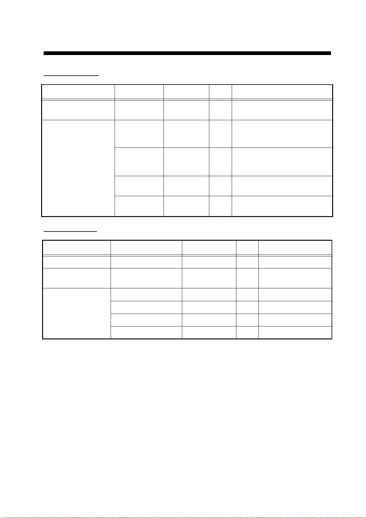
EQUIPMENT LISTS
Standard supply
Name Type Code No. Qty Remarks
Memory Card Interface
Unit
Installation Materials
(Select one.)
CU-300 - 1
CP03-27400 000-081-570 1 set For 5 m, MJ-A6SPF00 17-050C,
MJ-A3SPF0026-050C, and
CP03-27401
CP03-27410 000-081-571 1 set For 10 m, MJ-A6SPF0017-
100C, MJ-A3SP F00 26- 10 0C,
and CP03-27401
CP03-27440 000-083-403 1 set For 5 m, MJ-A3SPF0026-050C
and CP03-27401
CP03-27450 000-010-245 1 set For 10 m, MJ-A3SPF0026-100C
and CP03-27401
Option a l supply
Name Type Code No. Qty Remarks
Hanger FP03-10201 008-539-530 1 set For desktop mounting
Console Mounting
Kit
FP03-10203 001-011-710 1 set For bulkhead mounitng
Cable Assy MJ-A3SPF0026-050C 000-157-944-10 1 5 m, power cable
MJ-A3SPF0 026 -100C 000-157 -945- 10 1 10 m, power cable
MJ-A6SPF0017-050C 000-159-705-11 1 5 m, Ethernet cable
MJ-A6SPF0017-100C 000-159-706-11 1 10 m, Ethernet cable
vii
Page 10

1. MOUNTING
d
rod
The memory card interface unit can be flush mounted in a console, or mountd on a desktop or the
overhead.
Choose a m ounting location for th e unit consid ering the follow ing points:
• Leave s uffic ient space aro und the unit t o fa c ilita t e c hec k ing and ma int enance. See outline
drawing at the bac k o f this m anual for re c om m ended ma int enance spac e.
• Locate th e unit well aw ay fr om ex haust gas es and other act iv e gases.
• The location should be well ventilated.
• Choose a location where shock and vibration are minimal.
• Only the front panel is waterproofed.
Note: For flush mount or bulkhead mount, the DIP switch setting should be completed before
mountin g. See page 8.
1.1 Flush Mounting
1. Prepare a cutout in the mo unt ing location as below.
150.5+0.5
143+1
24+0.5
54+1
R2.25
2. Screw four threaded rod (M4×50, supplied) into holes on the front panel (reverse side).
Screw threaded rods into
these holes.
4.5
Rear view
3. Insert the unit into the cutout made at step 1.
4. Fix the unit with four spring, flat washers, and hex. nuts.
1
Threade
Page 11

Spring washer, flat washer and hex. nut
20
42
171
60
98
1.2 Desktop Mounting
This meth od requires th e optional h anger FP03 -10201.
Name: H anger (Typ e: F P03-10201, Code no. : 008-539-530)
Contents of kit FP03-10201
Name Type Code No. Qty
198
145
#100
Hanger 19-023-3081 100-316-250 1
Self-tapping screw
Pan head screw
φ5×20, SUS304
M4
×10, C2700W
000-162-608-10 4
000-163-167-10 4
1. Fasten four pan head screws (M4×10) to fix the hanger to the unit.
2. Fix the hanger with unit to the mounting location with four self-tapping screws (φ5×20).
2
Page 12

198
#20
163+0.5
171
179
#20
6 Fixing hole
100+0.5
41.5
2.2
62
42
198
#100
1.3 Overhead Mounting
This met hod requires th e optional kit F P03-10203.
Name: C onsole mounting kit (Ty pe: FP03 -10203, Code no.: 001-011-710)
Contents of kit FP03-10203
Name Type Code No. Qty
Mounting plate 19-023-3091 100-316-260 1
Pan head screw
Hex. nut M4 SUS304 000-863-106 4
Flat washer M4 SUS304 000-864-126 4
Spring washer M4 SUS304 000-864-256 4
M4
×10 C2700W
000-163-167-10 4
3
Page 13

1. Prepare four fix ing holes in the bulkhead whose dimensions are as shown below.
5
120+0.5
120+0.5
2. Fast en four pan he ad screws (M 4) to fix the mounting pl at e t o the unit.
3. Insert four studs at th e top o f th e mounti ng pla te in fi xi n g h oles made at ste p 1, and then pass
spring washers, flat washers and hex. nuts onto in that order from inside the bulkhead.
4. Tighten hex nuts to fix the unit.
#20
120+0.5
171
77
120+0.5
31.5
2.2
#20
Max. 8
102
42
14
63
198
Dimensions for overhead mounting
Nut (M4)
#100
4
Page 14

2. WIRING
There are three types of connec t ions:
• Connec t ion between one proc es s or unit and memory car d int erface un it .
• Connec t ion between one memory card int erf ace unit and multiple processor unit s
• Connection between two memory card interface un its and two pr ocessor units.
Note that the total number of card slots is maximum four in a series.
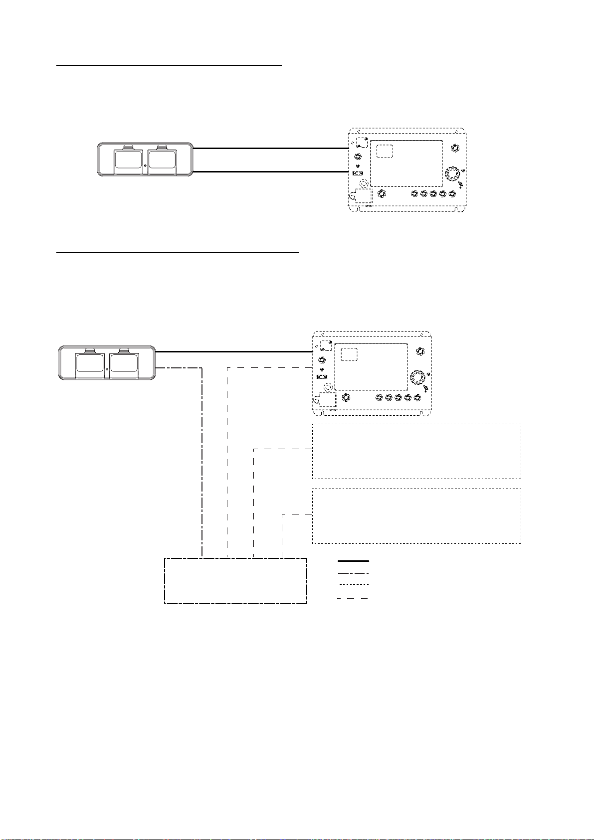
2.1 Connection between One Processor Unit and
One Memory Card Interface Unit
Ethernet cable
MJ-A6SPF0017-050C or 100C
POWER
GND
F.G.
321
NTSC/PAL
RGB OUT
OPTION
OUTPUT
12 VDC
CARD SLOT
0.3 A MAX
REMOTE FMD DISPLAY
DJ-1
INPUT
2
1
12-24 VDC
3
GND
NETWORK
Power cable
MJ-A3SPF0026-050C or 100C
DATA 3
CONT DATA 1
DATA 2
Ground wire
IV-1.25sq
(Local supply)
Ground
5
Page 15

2.2 Connection betwe en O ne Mem o ry Car d I nter fac e
Unit and Multiple Processor Units (Max. Three
Units)
Prepare th e f ollowing cables and connectors :
• Commercial LAN cable (CAT5, STC, straight)
• Cable assy, MJ-A6SPF0014-010C/050C/100C/200C/300C (option for NavNet VX2)
• Converter connector, MJA6SERMD/TM11AP8-005 (option for NavNet VX2)
Power cable
POWER
GND
F.G.
321
NTSC/PAL
RGB OUT
OPTION
OUTPUT
12 VDC
0.3 A MAX
MJ-A3SPF0026-050C or 100C
REMOTE FMD DISPLAY
DJ-1
Ground wire
IV-1.25sq
(Local supply)
Ground
INPUT
2
1
12-24 VDC
3
CARD SLOT
GND
NavNet VX2-BB
Processor unit
NavNet VX2 or
NavNet VX2-BB
Processor unit
NavNet VX2 or
NavNet VX2-BB
Processor unit
NETWORK
DATA 3
CONT DATA 1
DATA 2
Cable assy
MJ-A6SPF0014-010C/
050C/100C/200C/300C
(Option for NavNet VX2)
LAN cable
(CAT5, STP, straight,
local supply)
HUB
Converter connector
MJA6SRMD/TM11AP8-005
(Option for NavNet VX2)
6
Page 16

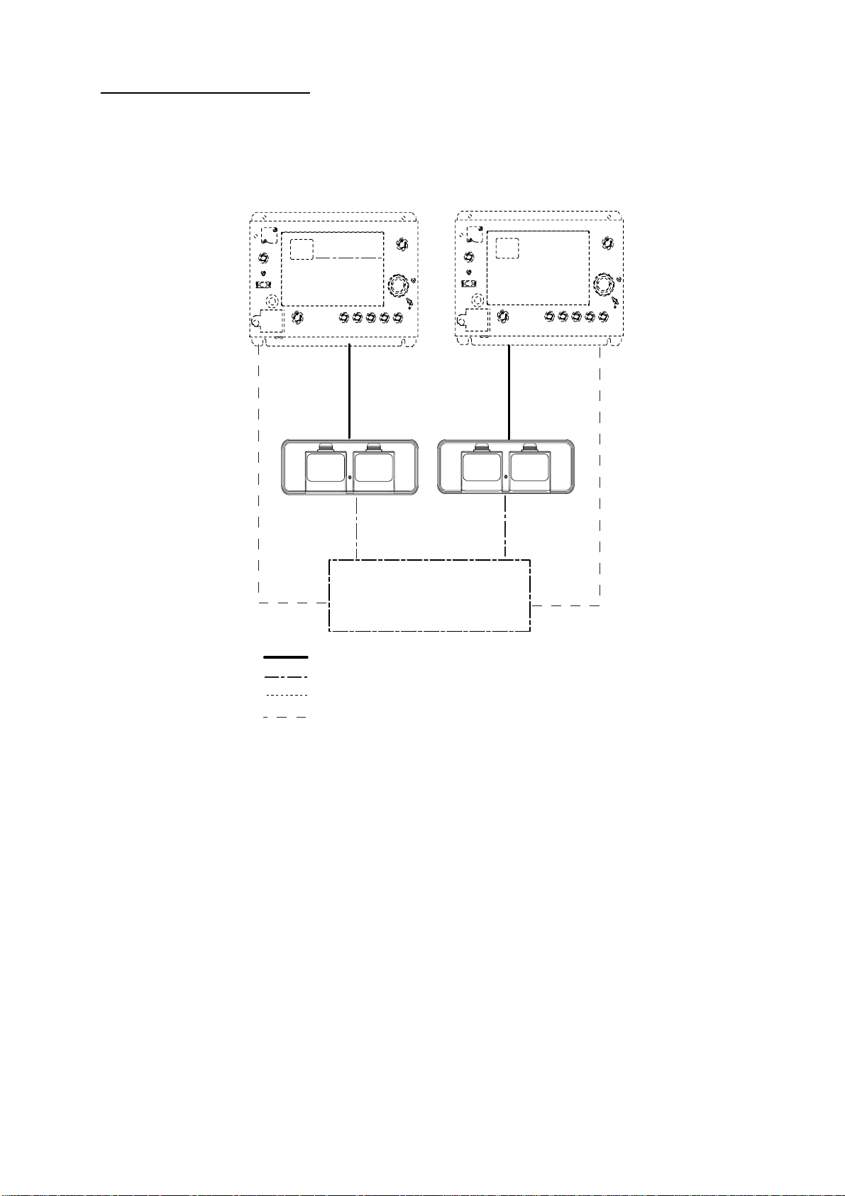
2.3 Connection between Two Memory Card
Interface Units and Two Processor Units
Prepare th e f ollowing cables and connectors :
• Commercial LAN cable (CAT5, STP, straight)
• Cable as s y, MJ-A6SPF 0014-010C/050C / 100C/200C / 300C (option for NavNet VX2)
• Conve rt er c onnector, MJA6S ER M D / T M11AP8-005 (opti on for NavNet VX2)
Power cable
POWER
F.G.
321
0.3 A MAX
GND
OUTPUT
12 VDC
NTSC/PAL
RGB OUT
OPTION
INPUT
2
1
12-24 VDC
3
CARD SLOT
GND
NavNet VX2-BB
Processor unit
NETWORK
CONT DATA 1
MJ-A3SPF0026-050C or 100C
REMOTE FMD DISPLAY
DJ-1
DATA 3
DATA 2
Converter connector
MJA6SRMD/TM11AP8-005
(Option for NavNet VX2)
Ground wire
IV-1.25sq
(Local supply)
Ground
LAN cable
(CAT5, STP, straight,
local supply)
NavNet VX2-BB
Processor unit
POWER
F.G.
3
0.3 A MAX
2
GND
OUTPUT
12 VDC
NTSC/PAL
RGB OUT
OPTION
INPUT
2
1
12-24 VDC
3
CARD SLOT
GND
Cable assy
MJ-A6SPF0014-010C/
050C/100C/200C/300C
(Option for NavNet VX2)
REMOTE FMD DISPLAY
DJ-1
DATA 3
NETWORK
CONT DATA 1
DATA 2
Power cable
MJ-A3SPF0026-050C or 100C
HUB
Converter connector
MJA6SRMD/TM11AP8-005
(Option for NavNet VX2)
Ground wire
IV-1.25sq
(Local supply)
LAN cable
(CAT5, local supply)
Ground
7
Page 17

Setting of the IP address for the second memory card interface unit
When connecting two memory card interf ace uni ts, ch ange th e DIP swit ch se tting on the second
unit as below to change its IP address. Note that the second unit is exclusively for reading chart
card.
1. Unfas ten two pan head screws (M3x 8) , a wing bol t a nd a washer for MJ co nnector at the rear
of the unit.
2. Unfasten four screws and the connector at the location shown below to remove the front
panel.
3. Unfasten four pan head screws at the inner front chassis to remove it.
4. Pull out the inner chassis to it.
5. Set the #4 segment of DIP switch S1 as below.
4 3 2 1
OFF
ON
S1
6. Re-assemble the unit.
PCB 19P1050
8
Page 18

3. OPERATION
3.1 Basic Operation
Card box
Card drive
Power lamp
(green)
Card drive
Insert the appropriate chart SD card (or memory card) for your area as below. For details of SD
cards, see the operator’s manual for NavNet VX-2.
(Strage for two cards)
1. Open the card drive.
2. Insert the card (label side up) prior to turning on the power at NavNet VX2-BB.
3. Clo s e t he lid.
To remove the card, f ollow the instr uctions sh own on the display of NavNet VX2 an d then co nfirm
that the power lamp on the front panel lights. Do not read/write the data.
Power lamp
Lights (g reen): The pow er is on.
Blinks: The unit is reading/writing data.
Card box
You can s to re t w o SD cards h ere.
Note 1: When the connection between NavNet VX2-BB and memory card interface unit is wrong,
the NavNet VX2-BB searches for chart data in the SD card for 50 seconds, and then returns to
the norm al operation . Th e display look s fr oz en, howev er normal operation wil l be restarted af te r
the search is completed.
Note 2:
To prevent loss of card data if the power sudd enly goes of f, it is recomm ended that
you periodically back up data to an SD card.
9
Page 19

3.2 Priority of Card Drives
The pr io rit y of c ard dr iv es is aut om ati ca ll y s et af ter tur ni ng t he po wer on. T his pr io rit y or d er v ar ie s
depen ding on the numb er of card dri v es connect ed.
One memory card interface unit
2
CU-300
1
NavNet VX2-BB
Processor unit
3
NavNet VX2 or
NavNet VX2-BB
Processor unit
4
NavNet VX2 or
NavNet VX2-BB
Processor unit
HUB
Unit and available chart card and memory card locations
The num bers in the tab le refer to the correspon ding units in th e f igure abov e.
Unit
Available chart card
locations
Available memory card
location
11 2 3 42
3
4
NavNet VX2
NavNet VX2-BB
NavNet VX2
NavNet VX2-BB
1 2 3 43
1 2 3 42
1 2 3 44
1 2 3 42
10
Page 20

Two memory card interface units
1
2
NavNet VX2-BB
CU-300
Processor unit
HUB
3
4
NavNet VX2-BB
Processor unit
Unit and available chart card and memory card locations
The numbers in the table refer to the corresponding units in the figure
above.
CU-300*
*: For the second CU-300, DIP switch setting is necessary.
Unit (priority)
Available chart card
locations
11 2 3 42
31 2 3 42
Available memory card
location
11
Page 21

FURUNO
CU-300
SPECIFICATIONS OF MEMORY CARD INTERFACE UNIT
CU-300
1 GENERAL
1.1 Number of card slot 1
1.2 Card storage 2 SD-card
1.3 Ethernet 100BASE-TX/10BASE-T, auto-negotiation
1.4 Cable Connection RJ-45, STP LAN (CAT5)
1.5 Card type (at February 2007)
ADTEC AD-SDH512/1G/2G, AD-SDPS128M/256M/512M/1G
BUFFALO RSDC-S64M/S128M/S256M/S512M/S1G/S2G/G512M/G1G/G2G
HAGIWARASYS-COM HPC-SD256M/SD512M2/SD1GM2/SD2GM2/SD256TP/SD512TP/
SD1GTP/SD128T/SD256T/SD512T/SD1GT/SD2GT
I/O DATA SD-128M/256M/512M/1G/2G, SDP-256M/512M/1G/2G
Kingston SD/1GBFE, SD/2GBFE
LEXER SD256/512/1GB-231
PANASONIC RP-SDR512/01G/02G-J1A, RP-SD128MBL1A, RP-SD256BJ1A,
RP-SDK512/01G/02G-J1A
PQI QSDS-256/512/1G/2G
SANDISK SDSDB-256/512/1024/2048-J60, SDSDH-512/1024/2048-903
2 POWER SUPPLY
12 VDC: 0.14 A, 1.7 W or less
3 ENVIRONMENTAL CONDITIONS
3.1 Ambient temperature -15°C to +55°C
3.2 Relative humidity 93% at 40°C
3.3 Degree of protection IP22 (IP55: flush mount or front panel only)
3.4 Bearing vibration IEC 60945-4
3.5 CE marking IEC 60945-4
4 COATING COLOR
N3.0
SP - 1 E3550S01A
Page 22

PACKING LIST
A-1
CU‑300‑G5/G10[GENERAL用]
19AZ‑X‑9852 ‑1
1/1
NAME
OUTLINE
DESCRIPTION/CODE№
ユニット UNIT
メモリーカードインターフェイス
MEMORYCARDINTERFACEUNIT
CU‑300
000‑010‑244‑00
工事材料 INSTALLATIONMATERIALS CP03‑27440/27450
ケーブル組品MJ
CABLEASSY.
MJ‑A3SPF0026‑050C
MJ‑A3SPF0026‑050
000‑157‑944‑10
000‑149‑445‑00
ケーブル組品MJ
CABLEASSY.
MJ‑A3SPF0026‑100C
MJ‑A3SPF0026‑100
000‑157‑945‑10
000‑149‑446‑00
工事材料
INSTALLATIONMATERIALS
CP03‑27401
008‑539‑520‑00
図書 DOCUMENT
取扱説明書
OPERATOR'SMANUAL
OME‑35501‑*
000‑165‑406‑1*
Q'TY
1
1
(*1)
1
(*1)
1
1
(*1)は、仕様選択品を表します。
(*1)INDICATESPECIFICATIONSELECTIVEITEM.
型式/コード番号が2段の場合、下段より上段に代わる過渡期品であり、どちらかが入っています。 なお、品質は変わりません。
TWOTYPESANDCODESMAYBELISTEDFORANITEM.THELOWERPRODUCTMAYBESHIPPEDINPLACEOFTHEUPPER
PRODUCT.QUALITYISTHESAME.
(略図の寸法は、参考値です。DIMENSIONSINDRAWINGFORREFERENCEONLY.)
19AZ‑X‑9852
Page 23

工事材料表
,
A-2
INSTALLATIONMATERIALS
番号
NO.
1
2
3
4
名 称
NAME
六角ナット 一種
HEX.NUT
ミガキ平座金
FLATWASHER
バネ座金
SPRINGWASHER
寸切ボルト
THREADEDROD
略 図
OUTLINE
CODENO.
TYPE
型名/規格
DESCRIPTIONS
M4SUS304
CODE
NO.
M4SUS304
CODE
NO.
M4SUS304
CODE
NO.
M4X50SUS304
M4X50SUS304
CODE
NO.
008‑539‑520‑00
CP03‑27401
000‑863‑106‑00
000‑864‑126‑00
000‑864‑256‑00
000‑162‑679‑10
000‑147‑539‑00
数量
Q'TY
4
4
4
4
03GO‑X‑9403
用途/備考
REMARKS
‑1
1/1
型式/コード番号が2段の場合、下段より上段に代わる過渡期品であり、どちらかが入っています。 なお、品質は変わりませ
ん。
TWOTYPESANDCODESMAYBELISTEDFORANITEM.THELOWERPRODUCTMAYBESHIPPEDINPLACEOFTHEUPPER
PRODUCT.QUALITYISTHESAME.
(略図の寸法は、参考値です。 DIMENSIONSINDRAWINGFORREFERENCEONLY.)
FURUNO ELECTRIC CO .
LTD.
03GO‑X‑9403
Page 24

Feb.13'07R.Esumi
D-1
Page 25

Feb.13'07R.Esumi
D-2
Page 26

Feb.13'07R.Esumi
D-3
Page 27

Page 28

9-52 Ashihara-cho,
*
00016540610
**00016540610
*
Nishinomiya, 662-8580, JAPAN
Telephone : +81-(0)798-65-2111
Fax :+81-(0)798-65-4200
The paper used in this manual
is elemental chlorine free.
・FURUNO Authorized Distributor/Dealer
All rights reserved.
Pub. No. OME-35501-A
(HIMA ) CU-300
Printed in Japan
A : MAY 2007
*00016540610**00016540610*
* 0 0 0 1 6 5 4 0 6 1 0 *
 Loading...