

Page 1

COLOR SCANNING SONAR
MODEL
CSH-7
Page 2

c
FURUNO ELECTRIC C O., LT D
9-52, Ashihara-cho,
Nishinomiya, Japan 662
Telephone: 0798-65-2111
Telefax: 0798-65-4200
All rights reserved.
Printed in Japan
PUB. No. OME-13020
(DAMI)
CSH-7
.
Your Local Agent/Dealer
FIRST EDITION : MAY 1997
Page 3
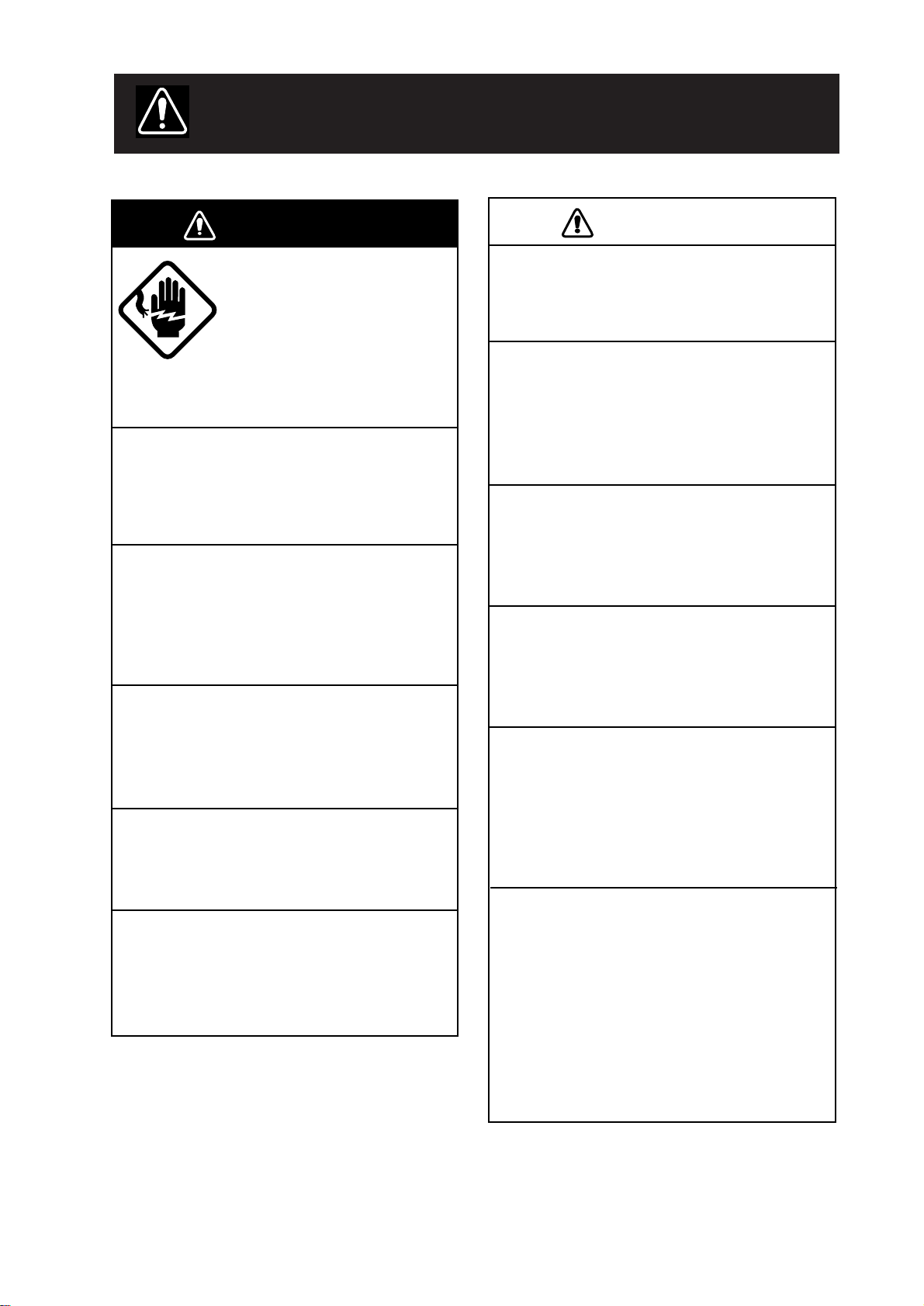
SAFETY INSTRUCTIONS
WARNING
Do not open the equipment.
Hazardous voltage which can
cause electrical shock, burn or
serious injury exists inside the
equipment. Only qualified
personnel should work inside
the equipment.
Do not disassemble or modify the
equipment.
Fire, electrical shock or serious injury
can result.
Turn off the power immediately if water
leaks into the equipment or the equipment is emitting smoke or fire.
Continued use of the equipment can cause
fire or electrical shock.
CAUTION
Use the proper fuse.
Use of a wrong fuse can result in fire or
permanent equipment damage.
Do not use the equipment for other than
its intended purpose.
Personal injury can result if the equipment
is used as a chair or stepping stool, for
example.
Do not place objects on the top of the
equipment.
The equipment can overheat or personal
injury can result if the object falls.
Do not exceed speed noted in the specifications when operating the equipment
or lowering or raising the transducer.
Do not place liquid-filled containers on
the top of the equipment.
Fire or electrical shock can result if a
liquid spills into the equipment.
Do not operate the equipment with wet
hands.
Electrical shock can result.
Keep heater away from equipment.
Heat can alter equipment shape and melt
the power cord, which can cause fire or
electrical shock.
The transducer may become damaged.
The zinc block attached near the
transducer must be replaced yearly.
The junction between the transducer and
main shaft may corrode, which can result
in loss of the transducer or water leakage
inside the ship.
POSSIBILITY OF INJURY
1. If breaker (hull unit) trips do the
following:
1) Turn off power swich on hull unit.
2) Wait 60 sec after breaker has tripped.
3) Press breaker.
2. Turn off hull unit before using hand
crank.
iiiiiiiiiiiii
i
Page 4

TABLE OF CONTENTS
FOREWORD
A Word to CSH-7 Owners ........................................................................................................ v
Features..................................................................................................................................... v
System Configuration ..............................................................................................................vi
OPERATIONAL OVERVIEW
Equipment Overview.............................................................................................................1-1
Display Unit Control Panel Description ................................................................................1-2
Turning the Power On/Off .....................................................................................................1-2
Adjusting Screen Brilliance, Control Panel Backlighting .....................................................1-3
Lowering the Transducer.......................................................................................................1-3
Selecting a Display Range.....................................................................................................1-3
Setting the Tilt Angle.............................................................................................................1-3
Adjusting the Gain.................................................................................................................1-7
MARKERS AND DA T A
Standard Markers and Data ...................................................................................................2-1
Optional Markers and Data....................................................................................................2-3
MENU OVERVIEW
Scan Menu Operation ............................................................................................................3-1
Menu-1, Menu-2, System Menu Operation...........................................................................3-4
FINE TUNING THE PICTURE
Eliminating Unwanted Feeble Echoes...................................................................................4-1
Displaying Surface Fish Clearly............................................................................................4-2
Suppressing Seabed Tail ........................................................................................................4-2
Suppressing Seabed and Sea Surface Reflections in Shallow Waters ...................................4-3
Rejecting Sonar Interference and Noise ................................................................................4-4
ADVANCED OPERATION
Measuring the Range and Bearing to a Target.......................................................................5-1
Detecting Fish Schools Aurally .............................................................................................5-1
Relocating Fish School for Easy Observation .......................................................................5-2
Function Keys (F1, F2)..........................................................................................................5-3
Event Markers, Own Ship Event Markers.............................................................................5-5
ii
Page 5

INTERPRETING THE DISPLAY
Seabed Echoes .......................................................................................................................6-1
Fish Schools...........................................................................................................................6-2
Sea Surface Reflections .........................................................................................................6-3
Wake ......................................................................................................................................6-3
False Echo by Sidelobe..........................................................................................................6-4
Noise and Interference...........................................................................................................6-4
MAINTENANCE
Display Unit Maintenance .....................................................................................................7-1
Hull Unit Maintenance ..........................................................................................................7-2
TROUBLESHOOTING
When the Transducer Cannot be Retracted ...........................................................................8-1
Diagnostic Tests .....................................................................................................................8-3
SPECIFICATIONS.......................................................................................................9-1
iii
Page 6

FOREWORD
A W ord to CSH-7 Owners
Congratulations on your choice of the FURUNO CSH-7 Color Scanning Sonar. We are
confident you will see why the FURUNO name has become synonymous with quality and
reliability.
For over 40 years FURUNO Electric Company has enjoyed an enviable reputation for quality marine electronics equipment. This dedication to excellence is furthered by our extensive global network of agents and dealers.
This equipment is designed and constructed to meet the rigorous demands of the marine
environment. However, no machine can perform its intended function unless operated and
maintained properly . Please carefully read and follow the recommended procedures for operation and maintenance.
We would appreciate hearing from you, the end-user, about whether we are achieving our
purposes.
Thank you for considering and purchasing FURUNO equipment.
Features
The FURUNO CSH-7 Color Scanning Sonar is a full-circle, multibeam electronic scanning
sonar which detects and instantaneously displays fish schools and underwater conditions in
16 colors on a 10" non-glare, high resolution CRT screen. Its ease of operation, versatility
and compact size make it the perfect match for any class of fishing vessel.
The main features of the CSH-7 are
• Compact size permits installation on smaller fishing boats.
• Vivid 16-color display provides intuitive recognition of seabed and concentration, distribution and volume of fish schools.
• Markers and indications keep the operator abreast of fishing conditions.
• Remote controller (option) provides for armchair control of gain, range and tilt functions.
• New gain, range or tilt setting appears in large characters whenever corresponding control is adjusted.
• Function keys automatically setup the equipment to perform specific task.
• High power MOS FET transmitter ensures reliable operation under any condition.
iv
Page 7
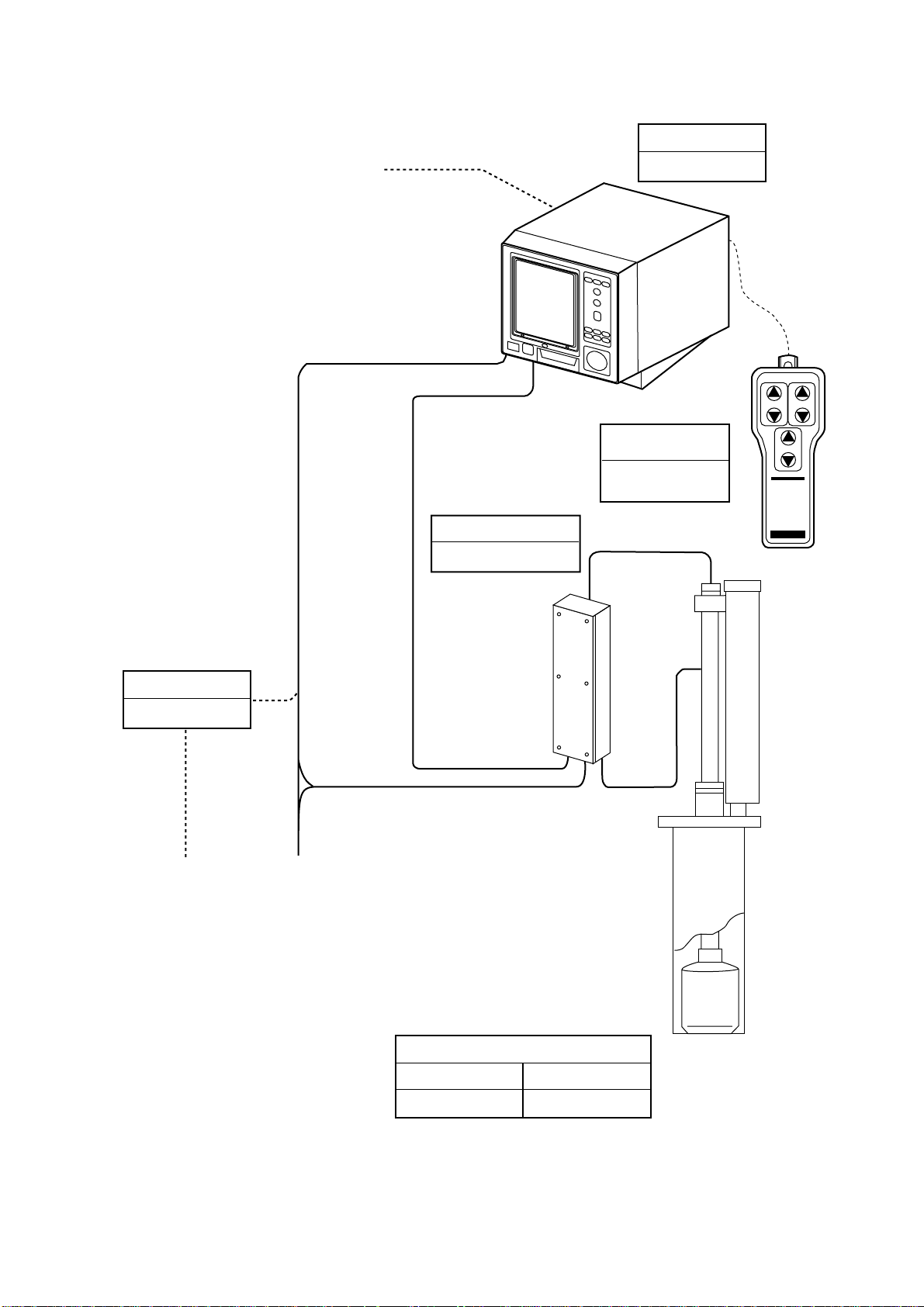
System Configuration
DISPLAY UNIT
NAVIGATOR
CURRENT INDICATOR
GYROCOMPASS
SPEED LOG
TRANSCEIVER UNIT
CSH-7020
(*)
CSH-7010
REMOTE
CONTROLLER
CSH-7040
(Option)
TILT RANGE
GAIN
RECTIFIER
RU-3424
(Option)
100-115 VAC/
200-230 VAC
1φ, 50/60 Hz
* Interface Module CSH-7050 (option)
required to connect external equipment.
Ship’s Mains
24 VDC
HULL UNIT
600 mm stroke
400 mm stroke
CSH-7030
CSH-7031
v
Page 8
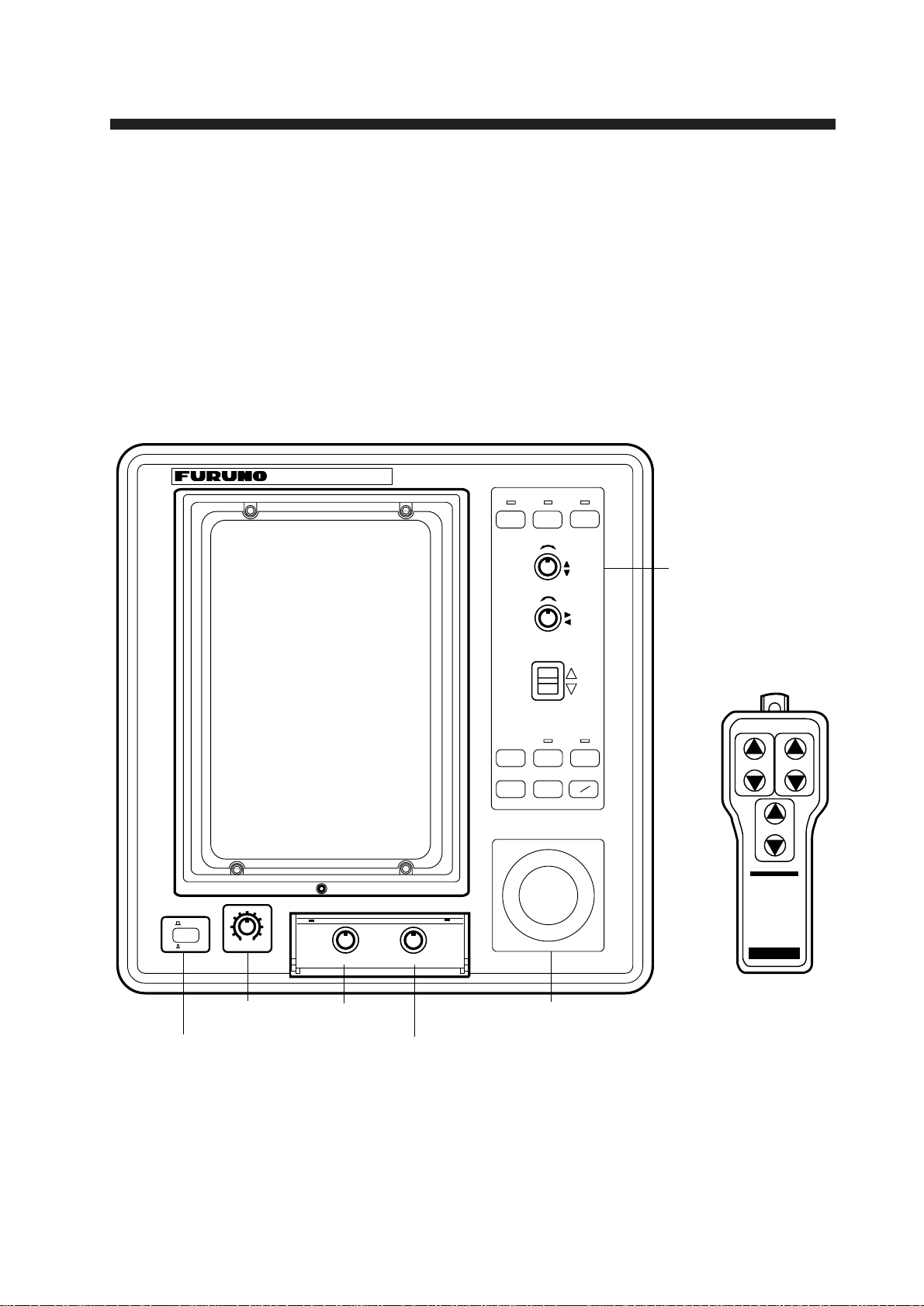
Equipment Overview
All operations of the CSH-7 are carried out through the display
unit and the remote controller (option). The uncluttered, straightforward control panel of the display unit provides intuitive operation. If you change a control setting you will see the associated
reaction on the display almost immediately.
The handy remote controller provides armchair control of range,
gain and tilt functions.
COLOR SCANNING SONAR CSH-7
OPERATIONAL OVER VIEW
c
– +
TX
d
Control
RANGE
– +
GAIN
TILT
MENU
F1 F2
OFF
CENTER
R
B
EVENT
ON
0
OFF
BRILL
10
DIMMER
AUDIO
panel
TILT RANGE
GAIN
POWER
switch
BRILL
control
DIMMER
Trackball
control
AUDIO
control
Figure 1-1 Display unit, Remote controller
1-1
Page 9
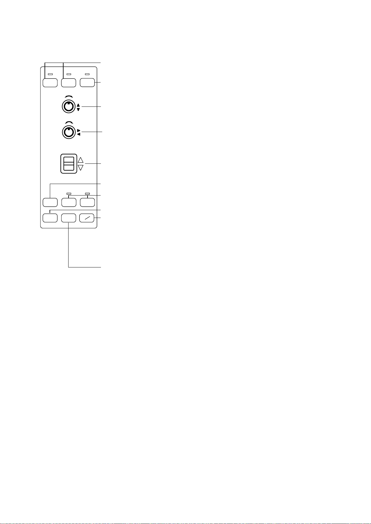
Display Unit Control Panel Description
Raises, lowers the transducer, respectively. Lamp above a key blinks
while the transducer is moving and lights when it stops.
d
c
– +
RANGE
– +
GAIN
TILT
MENU F1 F2
EVENT
OFF
CENTER
TX
Turns transmitter on/off; freezes the display. The lamp above the switch
lights when the transmitter is turned on and flickers when off.
Selects a picture display range. Also functions to select items on menu
screens. Note that this control turns endlessly in both directions.
Adjusts receiver sensitivity. Adjust for clear presentation of fish echoes.
Also functions to change settings on menu screens.
Tilts the sounding beam between 0° and 55°. The current angle always
appears on the screen.
Opens/closes the menu.
Function keys; execute assigned program when activated.
The lamp above a key lights when function is activated.
Inscribes/deletes an event marker.
R
Draws straight line, called bearing marker, from own ship position toward
B
the trackball marker and simultaneously draws a circle (range marker) with
a radius being the distance between the own ship marker and trackball
marker. Range and bearing data of the intersection of the two markers are
dislayed at the bottom of the screen. To turn off the range and bearing
markers, move the trackball mark near the own ship position and press
the R/B key.
Shifts screen center to cursor location.
Figure 1-2 Control panel description
Turning the Power On/Off
Power on
Press the power switch at the lower left corner of the display
unit to turn the power on/off. When the display unit is turned on
it checks itself for proper operation. (This test is described in
Chapter 8.)
Power off
Press the
above the switch lights and then press the power switch to turn
off the system.
c switch to retract the transducer . Wait until the lamp
1-2
Note: The transducer is automatically retracted into the tank even
if the power switch is pressed before retracting the transducer.
However, make it a habit to retract the transducer before turning
off the power.
Page 10
Adjusting Screen Brilliance, Control Panel Backlighting
The BRILL control adjusts screen brilliance, and the DIMMER
control adjusts control panel backlighting.
Lowering the Transducer
Press the d switch. The lamp above the switch blinks, and lights
when the transducer is fully lowered.
CAUTION
Do not exceed speed noted in the specifications when operating the equipment
or lowering or raising the transducer.
The transducer may become damaged.
Do not press the c switch during
lowering of the transducer, and do not
press the d switch during raising of the
transducer.
The equipment may become damaged.
Selecting a Display Range
Operate the RANGE control to select a display range. The range
selected appears at the top center of the screen.
Setting the T ilt Angle
The tilt angle shows the direction to which the sound wave is
emitted. When the sound wave is emitted horizontally, the tilt
angle is said to be zero degrees and when emitted vertically, 90
degrees.
To set a tilt angle, operate the TILT lever. Watch the tilt angle
indication at the top right corner on the screen. The tilt angle can
be set in one-degree steps from 0 to 55 degrees.
Finding a proper tilt angle is important when searching for fish.
Below are tips for selecting tilt angle.
1-3
Page 11
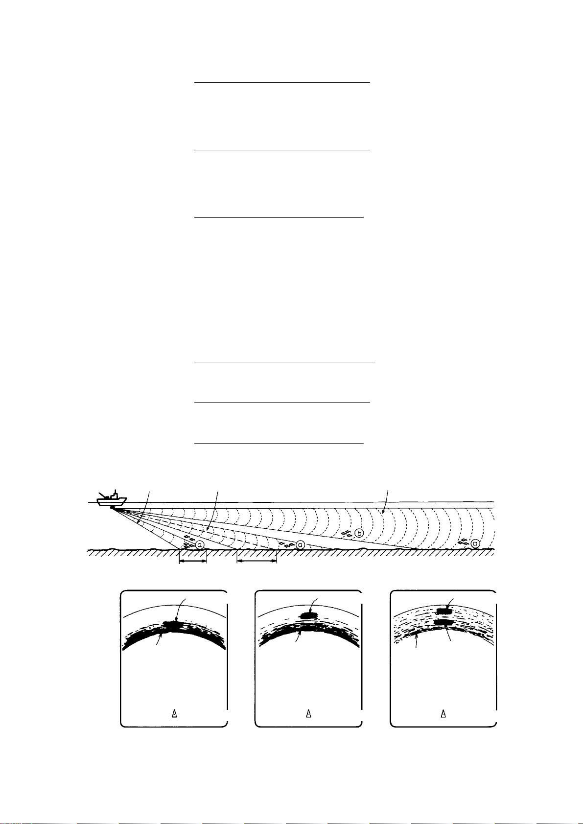
Seabed echo and tilt angle
Case 1: Tilt angle 30 to 40 degrees
This tilt angle will display the entire seabed since it is captured
by the full width of the beam.
Case 2: Tilt angle 10 to 20 degrees
This tilt angle will only display half the seabed since it is only
captured by the lower half of the beam.
Case 3: Tilt angle 0 to 10 degrees
This tilt angle may or may not capture the seabed since the re-
turning echo is weak.
How to discriminate fish echoes from the seabed
The figure below illustrates how two fish schools a and b are
displayed on the screen using three different tilt angles.
Case 1
Case 1: Tilt angle 30 to 40 degrees. Fish school is obscured by
the seabed.
Case 2: Tilt angle 10 to 20 degrees. Fish school is located above
the seabed (midwater).
Case 3: Tilt angle 0 to 10 degrees. Fish school is located close to
the seabed.
Case 2
Fish school aFish school a
Case 3
Fish school a
1-4
Seabed
Seabed
Case 1 Case 2
Figure 1-3 Fish echo and tilt angle
Seabed
Fish
school
b
Case 3
Page 12
Points to consider
• Normally, a vertically distributed fish school is a better sonar
target than the seabed, because it reflects the transmitted pulse
back toward the transducer.
• In case 3, both fish schools a and b are presented. Generally speaking, however, midwater fish schools tend to be lar ger
than bottom fish schools and they are often displayed near the
seabed on the display.
• It is difficult to detect bottom fish when they are not distributed vertically.
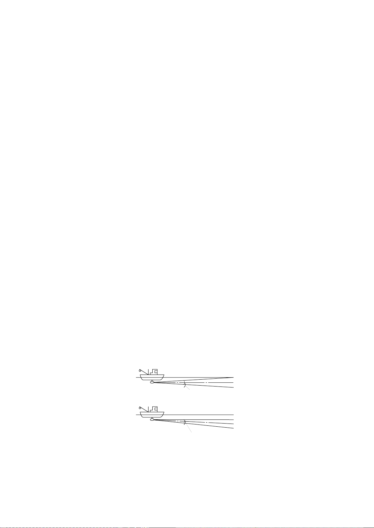
Tilt angle for surface fish
Sound emitted from the sonar transducer forms a circle-shaped
beam with a width in the vertical directions (vertical beam width)
of approximately 16 degrees for Tx and 19 degrees for Rx. The
tilt angle is indicated by the angle between the center line of the
beam and the horizontal plane. Then, if the tilt angle is set to 0
degrees, the center line is parallel with the sea surface and one
half of the emitted sound goes upward, toward the sea surface.
This causes one half of the emitted sound to be reflected toward
the transducer and displayed on the screen as sea surface reflections. When the sea is calm, since the sound is reflected just like
a light hitting a mirror at a narrow incident angle, it propagates
away and the sea surface reflections become negligible.
However if the sea is not calm enough, they will become dominant and interfere with observation of wanted echoes. To minimize these sea surface reflections and to search surface fish
schools effectively, the tilt angle is usually set between 5 and 6
degrees so the upper portion of the beam becomes almost parallel with the sea surface. When the sea is rough, it is often set to a
little larger angle.
Surface
Tilt angle 0°
Beam width Tx: 16°
Rx: 19°
Surface
Tilt angle 5-6°
Beam width Tx: 16°
Rx: 19°
Figure 1-4 Tilt angle and sea surface reflections
1-5
Page 13
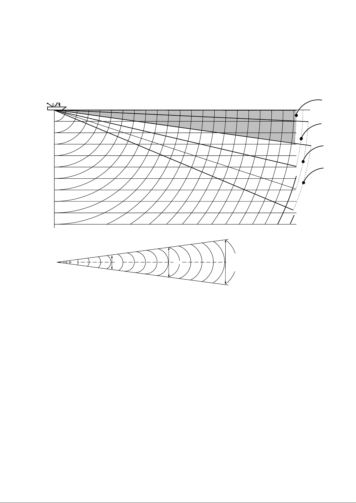
Suitable tilt angle
The figure below illustrates the relationship among tilt angle,
depth and detection range. Refer to it to find out the suitable tilt
angle for a given depth/detection range.
Tilt angle and beam coverage
20(40)
40(80)
60(120)
80(160)
100(200)
Depth (m)
200(400)
Vertical width of sonar beam
100 m100 m
100
(200)
200
(400)
200 m
300
(600)
300 m
Range (m)
400
(800)
0°
5°
10°
15°
16°
28 m
56 m
84 m
Figure 1-5 Tilt angle and beam coverage
1-6
Page 14
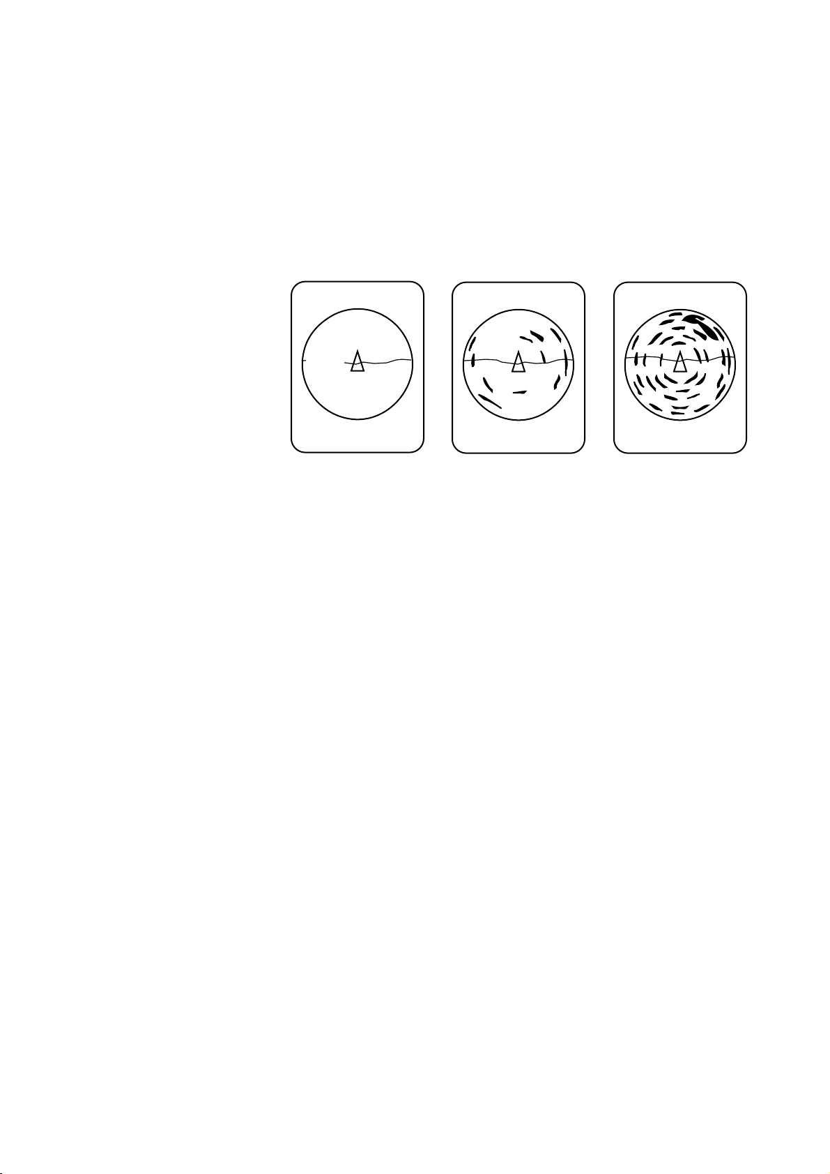
Adjusting the Gain
The GAIN control adjusts receiver sensitivity (gain). Adjust it
so fish echoes are clearly displayed with minimal noise on the
screen. Too high a setting not only displays excess noise and
makes it difficult to discriminate wanted echoes but also causes
seabed echoes to be painted in strong colors, resulting in echoes
being masked by seabed reflections. Normally, set the control
somewhere between positions “3” and “7”.
Gain low
Gain proper
Figure 1-6 Gain settings and resulting picture
Gain high
1-7
Page 15
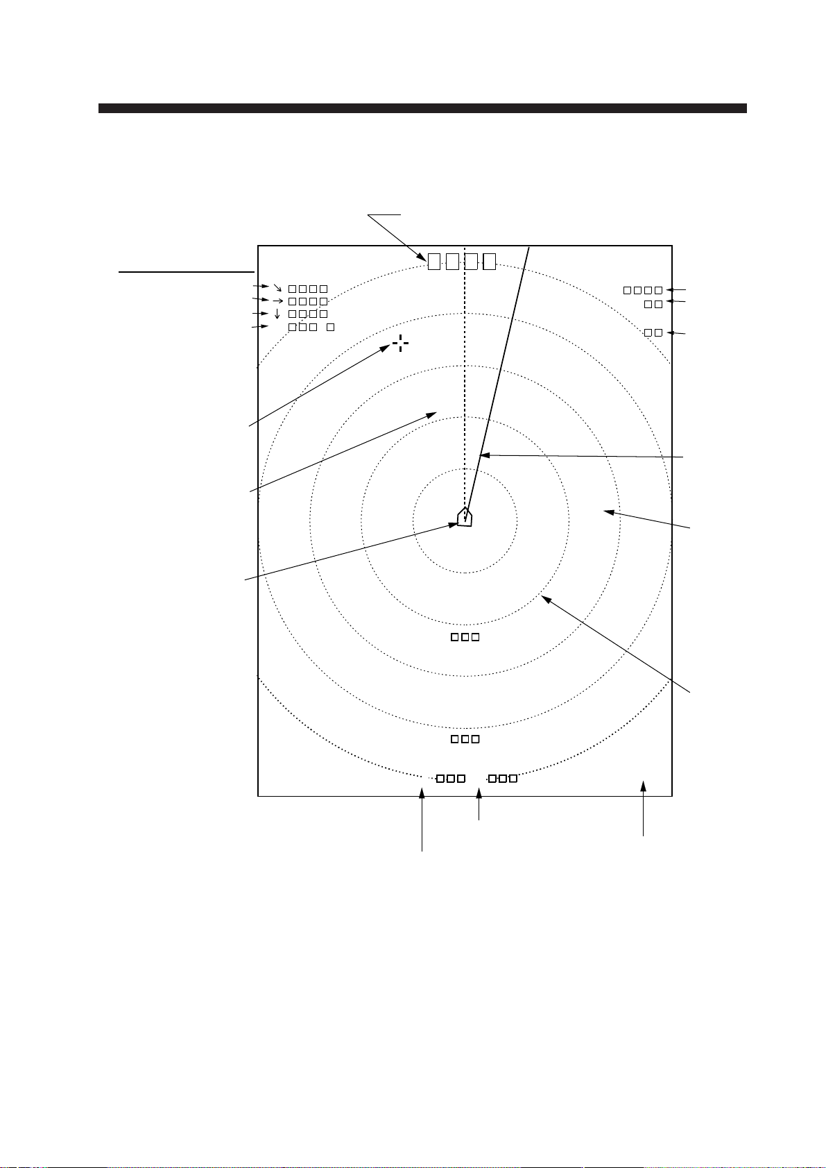
Standard Markers and Data
R
T
G
B
°
R
° B
Bearing of
bearing marker
Range to
range marker
Range
ring
Range
marker
Bearing
marker
Range
Tilt
Trackball marker data
Slant range
Horizontal range
Depth
True bearing
Trackball
marker
Heading
marker
Own ship
marker
Heading data
(Requires INTERFACE Board and gyrocompass.)
(M)
Unit of depth
measurement
Gain
MARKERS AND DA T A
Figure 2-1 Standard markers and data
2-1
Page 16
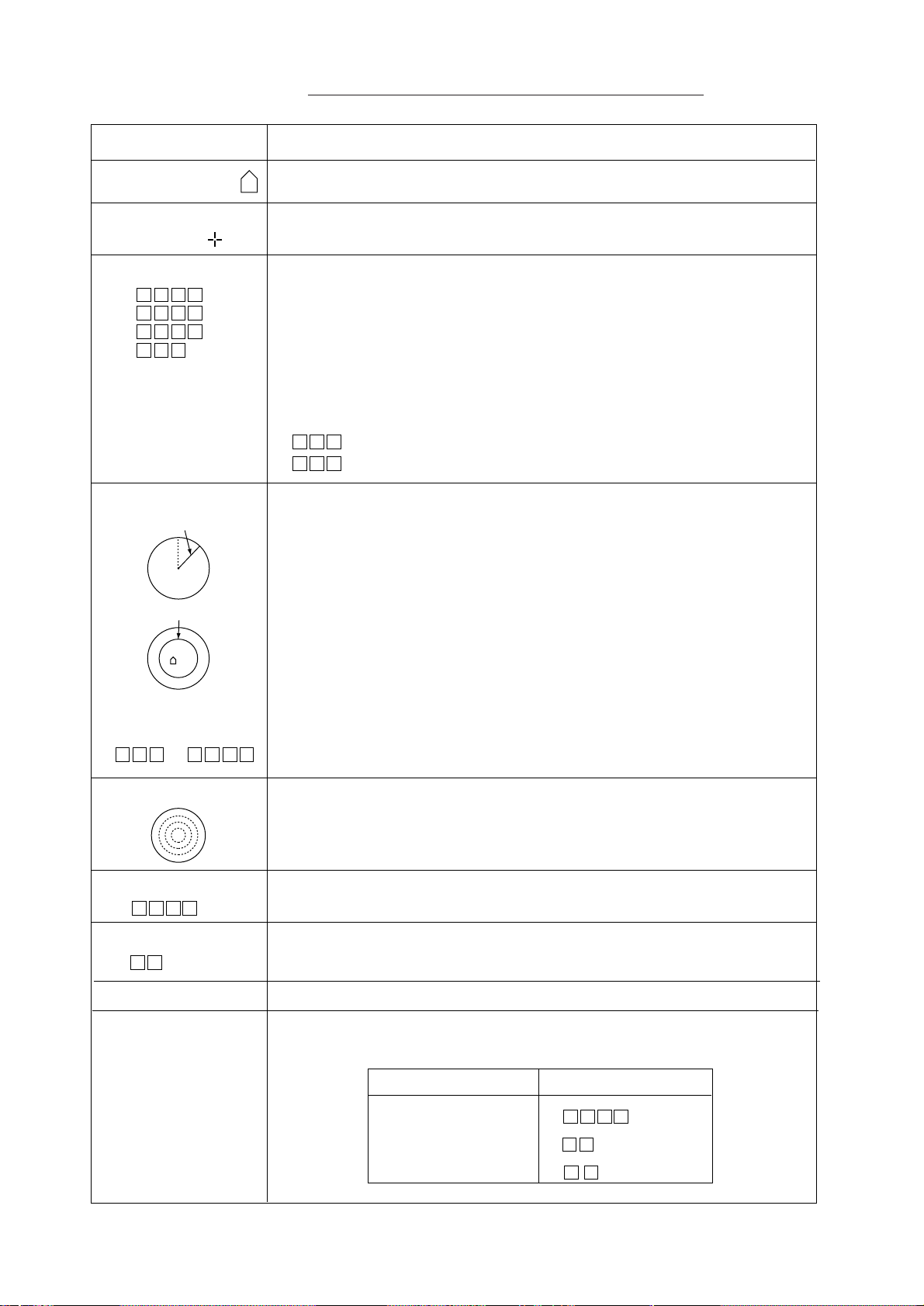
Table 2-1 Standard markers and data description
Marker/Data Description
Own Ship Marker
Trackball
Marker
Trackball Data
→
→
↓
B °
Bearing and Range
Markers
Bearing
marker
Range marker
Marks position on the screen. Direction of arrow is heading.
The trackball marker selects location for markers and own ship’s
position. The trackball moves the marker over the entire screen.
Trackball data:
→
: Slant range
→: Horizontal range
↓ : Depth
B : Bearing
Bearing is shown in 360¡ or –180¡ indication system, relative to ship’s
heading. In the latter case, "B" is indicated as follows:
BP.... on the port side
BP.... on the starboard side
The bearing marker bisects the trackball marker location when the R/B
key is pressed to monitor fish echoes with audible sound. Furthermore,
the radius of the range marker is at the trackball marker location. These
markers may be erased by placing the trackball marker near the own
ship marker and pressing the R/B key.
Range and Bearing
Marker Data
R ° B
Range Rings
Range Data
R
Tilt Data
T °
Gain
Setting Change
Data
The slant range to the range marker and the bearing of the bearing
marker are displayed.
The range rings are inscribed at intervals of 1/4 of the range in use.
Range ring data is also provided every two range rings. The range ring
interval can be changed from 1/4 to 1/2 through the menu.
Shows the range scale set with the RANGE control.
The tilt angle set with the TILT lever is displayed in 1¡ steps between
0¡ and 55¡.
Gain setting is displayed in increments of 0.5 between 0 and 10.
When the controls in the table below are changed new setting appears
in large characters at the top of the screen for five seconds.
Control Display
RANGE
TILT
R
T °
2-2
GAIN
G.
Page 17

Optional Markers and Data
184
16
( 199)
B E/N
187
186
16
B 23°S
E/N
R 300
T 5°
G 3.0
E
S
W
300
N
3
2
1
Trackball
marker
data
Tidal
current
marker
Own
ship
event
marker
Course
line
Electronic
bearing
scale
Heading indication
Latest
event
marker
Latest
event
marker
data
Past
event
marker
Trackball
marker
Various markers and data are available with connection of the
INTERFACE Board and appropriate external equipment.
Optional markers and data in the normal mode
Figure 2-2 Optional markers and data in the normal mode
2-3
Page 18

Optional markers and data in the normal plus text
mode
Heading indication
NW/N
Latest
event
marker
496
493
51
B 52°S
W
R 800T
T 5°
G 4.0
N
3
2
1
Past
event
marker
Latest
event
marker
data
Nav
data
367
38
( 165)
B 283° R 313 B 7°P
S
0.0
C
NW/W
D
174
T
17.0
34:
13.02N 135: 16.39E
C1:
1.1 315°
C2:
0.6 25°
C3:
1.2 64°
S
Figure 2-3 Optional markers and data in the normal plus text
mode
Position
Tidal current
data
2-4
Page 19

Table 2-2 Optional markers and data description
Marker Description
Latest Event Marker
Data
→
↓
()
B
°
Own Ship
Event Marker
Electronic Bearing
Scale
N
WE
S
Course Line Marker
Tidal
Current
Marker
3
2
1
The position data of the latest event marker, that is, horizontal range
(
→), current depth (↓) and bearing. ( ) shows the latest event
marker’s original depth, and remains unchanged regardless of ship’s
movement or tilt angle. When the event marker is erased the above data
disappears from the screen.
To erase an event maker, place the trackball maker on the event marker
and press the EVENT key.
You can plot ten own ship event markers on the course line. This marker can be erased.
The electronic bearing scale is available with gyrocompass connection.
It rotates with own ship’s movement.
With gyrocompass or speed log connection, own ship’s course line is
plotted by a solid line. Course line length is selectable from 5 to 10
times the range in use. Course line can be erased through the menu.
With current indicator connection, the tidal current marker shows the
speed and direction of three tide layers, numbered 1 through 3. The tide
speed is shown by vector length. However, no vectors develop if the
tide speed is 0.1 knots or less. Tidal current markers can be erased.
Tidal Current Data
C1: .
C2: .
C3: .
Nav Data
S: .
C:
D:
T: .
Own Ship Data
°
°
.N
.E
North Marker
In the normal mode plus text, tide speed and direction for three tide
layers appear in the text area. The method for displaying current
direction can be selected through the menu.
Own ship speed(S), Heading(C), Depth(D) and Water temperature(T) can be displayed on the text area. (Requires appropriate
sensors.)
The north marker is displayed with gyrocompass connection.
2-5
Page 20

The menu system consists of four menus: Scan menu, Menu-1,
Menu-2, and System. The Scan menu can be opened while transmitting, and contains items which the user will often change
during the course of operation. Menu-1 (similar to the Scan
menu), Menu-2 and System menus can be opened with the transmitter turned off. Menu-2 and the System menus contain items
which once set do not require frequent adjustment.
Scan Menu Operation
Displaying the scan menu
1. Press the TX switch to light the lamp (transmitter on state)
above it, if it is not already lit.
2. Press the MENU key. The first five items of the Scan menu
appear. (The figure below shows the entire menu.)
MENU OVERVIEW
DEGAUSS
AUTO DEGAUSS
DISPLAY MODE
TX OUTPUT
PULSELENGTH
TX CYCLE
TVG NEAR
TVG FAR
AGC
NOISE LIM
VP
IR
MARK ERASE
#
HOR BEAM ANGL
#
RES COL CURVE
#
COLOR EMPHASIS
FUNC1 PROG
FUNC2 PROG
USER PROG
**SCAN MENU ** (RANGE SW: U/D GAIN SW: L/R)
: EXECUTE
: OFF
: NORM
:10
:10
:10
:10
:10
:10
:10
: 0
: 0
: COURSE
: WIDE
: LINEAR
: 1 (LOW)
: USER1
: USER2
: USER1
TIMER
TEXT
SHIP
NARROW
1
2
SETUP1
SETUP1
USER2
GYRO
2
3
SETUP2
SETUP2
3
4 (HIGH)
SETUP3
SETUP3
Requires INTERFACE Board.
# Locked setting (in red). To change, select item, adjust GAIN control to
display YES, and press the TX key. Selected item appears in green;
setting may now be changed.
Figure 3-1 Scan menu
3-1
Page 21

3. Operate the RANGE control to scroll the menu and select
item. The selected item is highlighted in green and current
setting in white.
4. Operate the GAIN control to change setting.
5. Press the MENU key to register selections and close the menu.
Note: Gain or range cannot be changed while the Scan menu is
displayed.
Scan menu description
Table 3-1 Scan menu description
metInoitpircseD
SSUAGED ehtnoyekXTehtgnisserpybneercsehtfognissuagedselbanE
.neercsunem
SSUAGEDOTUA REMIT.neercsehtssuagedyllacitamotuaotwohstceleS
sessuagedORYGdna,setunimeerhtyreveneercsehtsessuaged
54yletamixorppasnrutpihsehtrevenehwneercseht °.
EDOMYALPSID.edomyalpsiderutcipastceleS
neercseritnenoerutciprenosehtsyalpsiD:MRON
txetdnaneercsfo01/9reppunoerutciprenossyalpsiD:TXET
,esruoc,deeps,noitisopsedulcnitxeT,01/1mottobno
.tnerrucladitdnahtped
TUPTUOXT .mumixam01,muminimsi0;spetsnevelenirewoptuptuosteS
aesnehwrewoprewolaesudna,esulamronrof01otteS
trohsnisloohcshsifserucsboohcedebaesrosnoitcelferecafrus
rewoptuptuoehttahtetoN.snoitareporetawwollahsdnaegnar
.degnahcsignittesehtretfasdnoces01segnahc
HTGNELESLUPsi0;sgnittesnevelenihtgneleslupnoissimsnartasteS
.mumixam,01dnamuminim
ELCYCXT tsegnolrof1;sgnittesnevelenietarnoititepernoissimsnartsteS
.tsetrohs,01dna
RAENGVT
RAFGVT
CGA rof,debaesehtsahcusstegratgnortsfoliatohcesesserppuS
.ylevitcepser
.gnittesdradnatsehtsi"2"ro"1"
,segnargnoldnatrohstaytivitisnesreviecerslortnoC
.gnittesdradnatsehtsi"5"noitisop;m001revO:RAF
.gnittesdradnatsehtsi"5"noitisop;m001nihtiW:RAEN
noitisoP.mottobehtottnecajdasloohcshsiffonoitingocerysae
MILESION roeulbthgilnineercseritneehtrevodeyalpsidesionstcejeR
.gnitteslausuehtsi"3"noitisoP.eulb
PV –doirepreporprofseohceehtfoegami-retfaehtstsujdA
stinehw"0"otteS.noitceridlaidarehtnidehctertseraseohce
.deriuqertonsinoitcnuf
3-2
Page 22

Table 3-1 Scan menu description (con’t.)
metInoitpircseD
RI ohcerehtoybdesuacecnerefretnidnaesionmodnarstcejeR
.sranosrosrednuos
ESAREKRAM.enilesruocrosrekrampihsnwollasesarE
LGNAMAEBROH ;esularenegrofediwtceleS.elgnamaeblatnozirohstceleS
EVRUCROLOCSER RAENIL.seohcegnortsdnakaewneewtebecnalabehtsteS
SISAHPMEROLOC ehtrehgiheht;yalpsidrolocehtniderfonoitroporpehtsteS
GORP1CNUF.yek1FehthtiwesuotmargorpstceleS
GORP2CNUF.yek2FehthtiwesuotmargorpstceleS
GORPRESU.smargorp2RESUdna1RESUfognimargorpselbanE
.noitanimircsidgniraebrettebrofworrran
.)htgnertsohcelautca(tupnihtiwyllanoitroporptuptuoseirav
kaew–seohcekaewezisahpmerettebotgnittesrehgihatceleS
seoggnittesehtsasrolocohceregnortsnideyalpsideraseohce
.RAENILsignittesdradnatsehT.rehgih
.dernideyalpsidseohcefonoitroporpehtretaergehtgnittes
Menu-1, Menu-2, System Menu Operation
3-3
Page 23

Displaying menu-1, menu-2, system menu
1. Press the TX switch to blink the lamp (transmitter off state)
above it, if it is not already blinking.
2. Press the MENU key. The last-used menu among Menu-1,
Menu-2, and System appears. The menu below is Menu-1.
** MENU - 1 ** (RANGE SW: U/D GAIN SW: L/R)
MENU MODE
DISPLAY MODE
TX OUTPUT
PULSELENGTH
TX CYCLE
TVG NEAR
TVG FAR
AGC
NOISE LIM
VP
IR
#
HOR BEAM ANGL
#
RES COLOR CURVE
#
COL EMPHASIS
FUNC1 PROG
FUNC2 PROG
USER PROG
DEGAUSS
AUTO DEGAUSS
: MENU - 1
: NORM
:8
:8
:10
:6
:7
:0
:0GPS
:0
:0
: WIDE
: LINEAR
: 1 (LOW)
: USER1
: USER2
: USER1
: EXEC
: OFF
MENU - 2
TEXT
NARROW
1
2
SETUP1
SETUP1
USER2
TIMER
SYSTEM
2
3
SETUP2
SETUP2
GYRO
3
4 (HIGH)
SETUP3
SETUP3
Requires INTERFACE Board.
# Locked setting
Figure 3-2 Menu-1
3. Operate the RANGE control to select item. The selected item
is highlighted in green and current setting in white.
4. Operate the GAIN control to change setting.
Note: Items in red are locked.
5. Press the MENU key to register selections and close the menu.
Menu-1 description
3-4
Page 24

This menu contains the same items as the Scan menu. See page
3-2 for description.
Menu-2 description
** MENU - 2 ** (RANGE SW: U/D GAIN SW: L/R)
MENU MODE
#
EXT KP SYNC
#
RANGE MARKER
#
BEARING SCALE
#
CURRENT MARK
#
COURSE MARK
#
HEADING INDI
#
CURRENT INDI
#
EVENT INDI
#
MARK INDI
#
POSITION DATA
: MENU - 1
: OFF
: 1/4R
: ON
: ON
: 10R
: 32 - AZI
: 32 - AZI
: 32 - AZI
: ±180°
: L/L
MENU - 2
ON
1/2R
OFF
OFF
5R
TRUE
TRUE
TRUE
360°
TD
Requires INTERFACE Board.
# Locked setting
metInoitpircseD
CNYSPKTXE.ffo/nonoitazinorhcnysPKlanretxesnruT
REKRAMEGNAR .egnarfo2/1roegnarfo4/1morfhtgnelrekramegnarstceleS
SYSTEM
OFF
OFF
±180°
±180°
360°
360°
ELACSGNIRAEB.ffo/noelacsgniraebcinortcelesnruT
KRAMTNERRUC.ffo/nokram)edit(tnerrucehtsnruT
KRAMESRUOC semit5rosemit01morftolpenilesruocehtfohtgnelstceleS
.esuniegnareht
IDNIGNIDAEH .gniraebeurtro,htumiza-23;noitacidnignidaehstceleS
IDNITNERRUC ,gniraebeurt,htumiza-23;noitacidni)edit(tnerrucstceleS
±081°063ro,°.
IDNITNEVE,gniraebeurtrohtumiza-23;noitacidnitnevestceleS
±081°063ro,°.
IDNIKRAM;noitacidnikramstceleS±081°063ro,°.
ATADNOITISOP fOeniL(POLro,edutignoldnaedutitalninoitisopsyalpsiD
.)noitisoP
Figure 3-3 Menu-2 description
3-5
Page 25

System menu description
** SYSTEM MENU ** (RANGE SW: U/D GAIN SW: L/R)
MENU MODE
#
HEADING ADJ
#
UNIT
#
SHIP’S SPD/BR
#
LOG PULSE
#
CI BAUD RATE
#
NAV FORMAT
#
NAV BAUD RATE
#
NAV DATA
MENU SELECT
#
SUB TEXT INDI
#
LANGUAGE
SELF TEST
DEFAULTS
Requires INTERFACE Board.
# Locked setting
metInoitpircseD
: MENU - 1
: 0°
: METERS
: LOG/GY
: 200
: 4800
: CIF
: 4800
: GPS
:LA
: LOCK
: OFF
: ENGLISH
: SINGLE
CONTI
: EXECUTE
MENU - 2
FEET
CI
400
2400
NMEA183
2400
LC
ALL
UNLOCK
ON
œ{Œ
PANEL
SIO
SYSTEM
FATHOMS
NAV
1200
NMEA182
1200
DEC
ESPANOL
COLOR
ECHO-1
PA/BRA
DR
DANSK
GRAY
ECHO-2
JDAGNIDAEH ehT.rorretnemngila)tinulluhni(egnalfrofsetasnepmoC
.eergedtseraeneht
TINU ro,smohtaf,teef,sretem;tnemerusaemhtpedfotinustceleS
.azarb/issap
RB/DPSS'PIHS ,ssapmocoryg/gol;tupnigniraeb/deepss'pihsfoecruosstceleS
.rotagivanro,rotacidnitnerruc
ESLUPGOL 004ro002;detcennocgoldeepsfosnoitacificepsstceleS
ETARDUABIC .duab0021ro,0042,0084;etarduabrotacidnitnerrucstceleS
TAMROFVAN ro3810AEMN,FIC;rotagivandetcennocfotamrofstceleS
ETARDUABVAN .duab0021ro,0042,0084;etarduabrotacidnitnerructceleS
ATADVAN CD,)CnaroL(CL,SPG;atadnoitisopfoecruosstceleS
.ytiroirptsehgiheht
otsinoituloseR.noitarepohctiwsEGNARhtiwsetatorerutcip
.goldeepsehtfolaunams'rotarepoehttlusnoC.elim/seslup
.rotacidnitnerrucehtfolaunams'rotarepoehttlusnoC
.rotagivanehtfolaunams'rotarepoehttlusnoC.2810AEMN
.rotagivanehtfolaunams'rotarepoehttlusnoC
.OTUAro)AnaroL(AL)gninokceRdaeD(RD,)acceD(
sahSPG;ytiroirptsehgihehthtiwatadnoitisopstcelesOTUA
3-6
TCELESUNEM.sgnittesskcolnu/skcoL
IDNITXETBUS.snaicinhcetybesuroF
EGAUGNAL.esuotegaugnalstceleS
TSETFLES.tsetflesastceleS
STLUAFED.yekXTehtgnisserpybsgnittestluafedotsteseR
Figure 3-4 SYSTEM Menu description
Page 26

FINE TUNING THE PICTURE
Eliminating Unwanted Feeble Echoes
Echoes from targets such as seabed and fish return to the transducer in order of distance to them, and when we compare their
intensities at the transducer face, those from nearer targets are
generally stronger when their reflecting properties are nearly
equal. The sonar operator will be quite inconvenienced if these
echoes are directly displayed on the screen, since he can not
judge the actual size of the target from the size of echoes displayed on the screen. T o overcome this inconvenience, the TVG
function is incorporated. It compensates for propagation loss of
sound in water; amplification of echoes on short range is suppressed and gradually increased as range increases so that similar targets are displayed in the similar intensities irrespective of
the ranges to them.
The CSH-7 has two TVG functions, NEAR and FAR, and they
mainly compensate for propagation loss on short and long ranges
respectively, centered at the ranges shown below . The higher the
TVG setting the greater the amplification of echoes.
Near
About 100 m
Figure 4-1 Principle of TVG
The TVG is also used to suppress unwanted echoes and noise
which appear in a certain range area on the screen such as sea
surface reflections and cruising noise. To set TVG properly, do
the following:
How to adjust TVG
Far
1. Press the MENU key to display the Scan menu.
2. Set both TVG NEAR and TVG FAR to “5”. These are the
standard settings and you can maintain them in most cases.
3. When sea surface reflections or plankton (displayed in weak
colors) disturb the picture, decrease TVG NEAR by 1 or 2 to
eliminate it.
4-1
Page 27

4. Locate a fish school on a long range setting which is approaching own ship. Adjust the tilt to keep the fish school in
the center of the sonar beam, namely , fish school is displayed
in strongest colors possible. Confirm that the fish echo is
displayed in the same color as it approaches. If the color suddenly changes to weaker colors as the fish enters FAR and
NEAR areas, the TVG is improperly set. Adjust the TVG. If
this again produces sea surface reflections and noise try to
remove them with AGC and NOISE LIM on the Scan menu.
5. Press the MENU key to close the menu.
Displaying Surface Fish Clearly
When you are searching for surface fish with the tilt set to a
narrow angle, sea surface reflections may disturb or mask wanted
fish echoes. In this case, in addition to the TVG adjustment described earlier set the AGC between positions “0” and “3” on
the Scan menu.
Suppressing Seabed Tail
As noted earlier, fish schools (echoes) located near the seabed
are sometimes difficult to detect because you have to discriminate them in the seabed reflections. The AGC and
PULSELENGTH in the Scan menu, if used properly, decrease
the tail of seabed reflections, making it easier to discriminate
bottom fish.
AGC
The AGC functions to automatically reduce the receiver gain
only against strong echoes such as the seabed or a large fish
school. Since weak echoes remain unaffected, a small fish school
becomes easier to detect. Adjust it so that the AGC works only
on seabed reflections. Do not set it too high; weak echoes may
be missed.
Pulselength
4-2
The pulselength control determines the length of the transmission pulse emitted into the water. While a longer pulse is advantageous for long range sounding, it has the disadvantage of being
poor in discrimination of targets, that is, ability to separate several closely located targets. When searching bottom fish, therefore, it is useful to shorten the pulselength in order to separate
Page 28

fish echoes from seabed reflections. Decrease the
PULSELENGTH setting on the Scan menu to shorten the
pulselength. For search of surface and midwater fish in which
seabed reflections are not so strong, use the longest pulselength
“10”.
Suppressing Seabed and Sea Surface Reflections in Shallow Waters
In shallow fishing grounds with hard or rocky bottom, seabed
reflections often interfere with wanted fish echoes and they can
not be eliminated sufficiently with the aforementioned TVG and
AGC, especially when the TILT is set to a larger angle in order
to track fish schools approaching within 400 m. In such cases
try to reduce the output power with OUTPUT in the Scan menu
without turning down the GAIN. The picture becomes clearer
when output power is reduced rather than when the GAIN is
decreased as illustrated below.
WRONG
METHOD
CORRECT
METHOD
Fish echo
TVG and AGC
adjusted with
OUTPUT kept high
OUTPUT decreased
with GAIN kept
constant
Fish echo
weakened
Fish echo
Figure 4-2 How to suppress seabed and sea surface reflections
in shallow waters
4-3
Page 29

Rejecting Sonar Interference and Noise
While observing the sonar picture, you may encounter occasional
or intermittent noise and interference. These are mostly caused
by on-board electronic equipment, engine or propeller noise, or
electrical noise from other sonars being operated nearby.
Identifying noise source
T o eliminate noise effectively , you should first identify the noise
source as follows:
1. Turn off the TX switch and operate all on-board equipment
one by one while observing the picture.
2. Run the boat at various speeds to check if the noise is speed
dependent.
If neither of the above two steps has effect on the picture, adjust
the IR (Interference Rejector) and NOISE LIM (Noise Limiter)
on the Scan menu as follows.
Rejecting noise with IR on the scan menu
This control is similar to the interference rejector on echo sounders and radars. It is effective for rejecting random noise and sea
surface reflections in rough sea conditions. Set it so that noise is
just eliminated. Do not use an unnecessarily high setting since it
may also reject small wanted echoes.
Rejecting noise with NOISE LIM on the scan menu
W eak, unwanted reflections, colored light blue or green, are displayed when water is contaminated or plankton layers exist or
due to ship's noise. These echoes gradually become bluish as the
NOISE LIM setting is raised. Usually , setting “3” or “4” is suitable.
4-4
Page 30

Rejecting interference with TX cycle
When other sonars operate nearby at the same transmission interval as that of own ship’s sonar , an interference ring caused by
other sonars is displayed. T o erase the interference ring from the
screen, reduce the TX CYCLE setting on the Scan menu.
Interference
TX CYCLE High TX CYCLE Lowered
Figure 4-3 How TX cycle works
Note: When the sonar is used in a shallow water with the range
set between 100 m and 200 m and the TX CYCLE at “10”, seabed reflections may appear on the screen. Reduce the TX CYCLE
setting to “7” or “8” to reject them.
Selecting horizontal beamwidth
If you wish to have better bearing discrimination (ability to distinguish two closely located targets at the same range and different bearings) for fish schools and also wish to examine the
contour of seabed, select HOR BEAM ANGL to NARROW on
the Scan menu.
4-5
Page 31

ADVANCED OPERATION
Measuring the Range and Bearing to a Target
Operate the trackball to place the trackball marker (+) on the
target you want to measure the range and bearing. The range
and bearing are displayed at the top left corner on the screen.
Trackball marker
Slant range
Horizontal range
Depth
Bearing
Figure 5-1 Location of range and bearing indications
Note: The bearing is shown in either 360° or 180° indication
system relative to the ship’s heading. In the latter case, “B” is
indicated as follows:
B
B P ------- on the port side
B S ------- on the starboard side
The 360° or 180° indication system can be selected on Menu-2.
Detecting Fish Schools Aurally
Occasionally you will be preoccupied with other tasks and unable to concentrate on watching the sonar picture. In such cases
you can use the audio function to aurally monitor fish echoes
through the built-in speaker.
1. Operate the trackball to move the trackball marker to the
direction you want to monitor through the speaker.
2. Press the R/B key. The bearing marker will appear in the
direction of the trackball mark and echoes in that direction
are monitored through the speaker. Adjust the volume with
the AUDIO control on the front panel.
3. To turn off the audio function, erase the bearing marker by
placing the trackball marker near own ship marker and pressing the R/B key.
5-1
Page 32

Trackball marker
Bearing
marker
Figure 5-2 Area monitored in audio function (sample)
Relocating Fish School for Easy Observation
When a fish school is located near the edge of the screen and
inconvenient for observation, use the off-center function to relocate the fish school to the desired place on the screen.
Fish echo
Fish
echo
OFF CENTER
key turned on
Own
Trackball
marker
ship
Figure 5-3 Off-center function
1. Move the trackball marker to the position where the own
ship mark is to be moved.
2. Press the OFF CENTER key.
3. To cancel the off-center function and shift own ship marker
back to the center of the screen, press the OFF CENTER key
again.
5-2
Page 33

Function Keys (F1, F2)
Function keys F1 and F2 work like the auto dialing feature on a
telephone, instantly calling out desired settings to perform specially assigned functions. These keys provide optimum sonar
settings for a specific purpose with a single key operation.
Each function key can be assigned a combination of particular
sonar settings which will be most suited to a specific objective,
for example, detection of a fish school. Five programs are available: two user programs (User 1, 2) and three task-specific programs (Setup 1, 2, 3). The default settings of these programs are
shown in the table below. Note that the “Setup” programs cannot be changed.
Table 5-1 Default programs
gnitteSmargorP
metI
2,1resU
TUPTUOXT0180101
HTGNELESLUP 282 01
ELCYCXT01010101
RAENGVT 3533
RAFGVT 7678
CGA 3132
MILESION 5354
RI 1211
PV 1111
ELGNAMAEBROHWORRANWORRANWORRANWORRAN
EVRUCROLOCSERRAENIL1RAENIL1
SISAHPMELOC 4343
1puteS
)loohcshsiF(
2puteS
)feer,kcerW(
3puteS
egnargnoL(
)noitceted
5-3
Page 34

Programming user programs
1. Press the TX switch to blink the lamp above it, if it is not
already blinking.
2. Press the MENU key and select Menu-1.
3. Using the RANGE and GAIN controls, set menu options as
desired.
4. Operate the RANGE control to select USER PROG.
5. Operate the GAIN control to select USER1 (for F1 key) or
USER2 (for F2 key).
6. Press the TX key to register the settings.
7. Press the MENU key to register settings and close the menu.
Note: When you change the contents of USER 1 or USER 2, do
the next procedure “Selecting program to use”.
Selecting program to use
1. Press the F1 or F2 key to light the lamp above it.
2. Press the TX switch to blink the lamp above it, if it is not
already blinking.
3. Press the MENU key and select Menu-1.
4. Operate the RANGE control to select FUNC1 PROG or
FUNC2 PROG, slected at step 1.
5. Operate the GAIN control to select program to use; USER1
(or USER2), SETUP1, SETUP2, or SETUP3.
6. Press the TX key to register the setting.
7. Press the MENU key to close the menu.
Enabling, disabling a program
Press the F1 or F2 key to light the lamp above it to enable program. Press key again to disable.
5-4
Page 35

Event Markers, Own Ship Event Markers
The event marker denotes important items on the display, such
as a fish school, and the own ship event marker marks own ship
position. T en event markers and ten own ship event markers may
be entered. The CSH-7 denotes the latest event marker as
other event markers as +. The own ship event marker is a triangle
dest corresponding marker is erased to make room for the latest.
Note that this function requires a gyrocompass (navigator for
own ship event marker) and the INTERFACE Board.
Entering an event marker, own ship event marker
1. Place the trackball marker on the location desired for an event
2. Press the EVENT key . The latest event marker appears at the
.When more than ten of either marker is entered the el-
marker . For own ship event marker, place the trackball marker
at own ship marker at screen center .
cursor location and event marker data (horizontal distance,
present depth, depth when marker was plotted, and bearing)
is displayed at the lower left side of the screen.
and
Horizontal range
Present depth
Depth when marker plotted
Bearing
184
16
( 199)
B 283°
Figure 5-4 Latest event marker data
Erasing all own ship event markers
All own ship event markers can be erased as follows:
1. Press the MENU key to display the SCAN menu.
2. Select MARK ERASE.
3. Select SHIP.
4. Press the MENU key.
Erasing an event marker
1. Place the trackball marker on the event marker.
2. Press the EVENT key.
5-5
Page 36

Seabed Echoes
(A) Flat seabed
Tilt angle: 10° to 15°
INTERPRETING THE DISPLAY
When the tilt angle is widened, the seabed echo illustrated below will appear on the display. When the tilt is narrowed, the
seabed trace becomes wider and weaker. By observing the seabed condition on the display, the skipper can prevent net damage.
Narrow tilt angle
Only half of
vertical beam width
captures the seabed.
(B) Flat seabed
Tilt angle: 20° or more
(C) Sloping seabed
Tilt angle: 20° or more
Seabed is displayed
narrower and in
stronger colors when
compared to (A).
Shallow bottom
is displayed in
a strong color
and with a
short tail.
Figure 6-1 Seabed echoes
Seabed
6-1
Page 37

Fish Schools
(A) Sea surface fish
Tilt angle: -5° to 10°
A fish school appears as a mass of echoes on the screen. The
color of the mass shows the density of fish schools on the sonar
beam. To find distribution and center point of a fish school, try
several different tilt angles.
Seabed echo not
Fish
school
Sea surface
reflections
displayed because
of narrow tilt angle.
Sea surface
reflections are
present.
(B) Midwater, bottom fish Tilt angle: 30° or more
Fish echo which appears before seabed can be detected.
Tilt angle: -0° to 20°
Fish echo which appears together with
or after seabed can be detected.
school
Seabed
Fish
school
Large midwater
fish school is
present.
Fish
Seabed
6-2
Figure 6-2 Fish schools
Page 38

Sea Surface Reflections
T o reduce sea surface reflections, set the tilt angle to 5° or higher,
so the upper edge of the sonar beam does not hit the sea surface,
or adjust TVG. When a narrow tilt angle is used, sea surface
reflections cover a large area as illustrated below.
W ake
Sea surface
Tx 16°
Rx 19°
Sea surface
Tx 16°
Rx 19°
Tilt angle
indication
Sea surface
reflections
Figure 6-3 Sea surface r eflections
A wake produced by own ship or another ship can be a strong
reflecting object when a narrow tilt angle is used. As the wake
appears as a thick continuous line, it can be easily distinguished
from a fish school. A wake contains many air bubbles which
attenuate ultrasonic energy, making it difficult to sound beyond
the wake.
Own
ship
Other
ship
Own ship's
screw noise
Wake produced
by other ship
Own ship's
screw noise
Figure 6-4 Wake appearance on the display
Own ship's wake
(produced when
own ship turned)
6-3
Page 39

False Echo by Sidelobe
An ultrasonic wave is emitted only in the direction set by the
TILT lever, however there are some emissions outside the main
beam. These are called sidelobes. The ennergy of the sidelobe is
fairly weak but when the water is comparatively shallow and the
bottom is rocky and hard, strong signals are detected by the
sidelobe. These are represented on the display as a false echo as
shown below.
Sidelobe
Sidelobe
Mainlobe
echo
Sidelobe
echo
The seabed echo
detected by sidelobe
appears at a certain
tilt angle when the
sidelobe points
vertically.
Figure 6-5 Sidelobe echoes
Noise and Interference
Interference from a sonar on board another ship appears on the
screen as shown in (A) below . This interference can be suppressed
by changing the TX CYCLE setting in the Scan menu. Interference from electrical equipment on board own ship appears as
shown in (B) below . Noise from marine life appears on the display as shown in (C). Electrical interference and marine life noise
can be suppressed with IR on the Scan menu.
6-4
(A) Interference from
other sonar
(B) Electrical
interference
Figure 6-6 Noise and interference
(C) Marine life noise
Page 40

WARNING
Do not work inside the
equipment unless totally
familiar with electrical
circuits.
Hazardous voltage which can
cause electrical shock, burn or
serious injury exists inside the
equipment.
Display Unit Maintenance
MAINTENANCE
Handle the equipment with care.
Clean the screen and filter
regularly. Cover the equipment
when it is not in use.
An anti-static spray may be used
to clean the screen. Do not use
chemical-based cleaners; they can
remove paint and markings.
Keep magnets and cassette tapes
away from the display unit.
Damage can cause corrosion.
DISPLAY UNIT
Figure 7-1 Display unit maintenance
Keep heater away from the
equipment.
Heat can damage the
equipment. Allow sufficient
ventilation.
Magnets or magnetic material can
can distort the picture.
7-1
Page 41

Hull Unit Maintenance
CAUTION
The zinc block near the transducer must
be replaced yearly.
The junction between the transducer and
main shaft may corrode, which can result
in loss of the transducer or water leakage
inside the ship.
HULL UNIT
Apply MOLYTONE grease
#2 every six months.
Raise transducer and coat
main shaft with
DAPHAECOROAEX #2
every six months.
Dry dock ship and clean
transducer face yearly.
Apply single coat of
"MARINE STAR 20 Mod
(Red-N)" anti-foulant to
transducer face to keep
marine life off the transducer.
Figure 7-2 Hull unit maintenance
7-2
Page 42

TROUBLESHOOTING
WARNING
Do not work inside the
equipment unless totally
familiar with electrical
circuits.
Hazardous voltage which can
cause electrical shock, burn or
serious injury exists inside the
equipment.
When the Transducer Cannot be Retracted
When the transducer cannot be completely retracted within 35
seconds after pressing
the screen center and the alarm sounds. If this occurs do the
following:
1. The power switch cannot be turned off because the transducer cannot be retracted. Turn off the main breaker for the
transceiver unit to stop operation.
2. Confirm that the net is not entwined around the transducer.
3. Confirm that the breaker inside the hull unit is on.
4. Check the mains fuse in the transceiver unit.
5. Apply the power again. Check if the transducer is retracted
in the tank. If it is not, the main shaft may be bent. Cut off
the power again and manually raise the transducer up to the
highest position possible by the hand crank. See the next
page for instructions.
c, XDCR NOT RETRACTED! blinks at
8-1
Page 43

Hand crank
CAUTION
POSSIBILITY OF INJURY
1. If breaker (hull unit) trips do the
following:
1) Turn off power swich on hull unit.
2) Wait 60 sec after breaker has tripped.
3) Press breaker.
2. Turn off hull unit before using hand
crank.
POWER ON/OFF LED (Green)
DOWN command LED (Red)
Breaker
Cable gland
POWER
8A
switch
Breaker
(Bottom view)
Shaft gear
Motor gear
Breaker ON/OFF state
ON
OFF
How to use the hand crank
1. Turn off the POWER switch on the hull unit.
2. Remove gear cover.
3. Attach hand crank to shaft gear or motor gear.
a) When crank is attached to shaft gear
(Requires greater force but less turns.)
Shaft gear
Hand crank
Tighten screw.
(Use screw from
cover.)
Shaft moves 600 mm
per 120 turns of crank.
Figure 8-1 How to use the hand crank
b) When crank is attached to motor gear
(Requires less force but more turns.)
Motor gear
Tighten screws.
(Use screw from
cover.)
Shaft moves 600 mm
per 210 turns of crank.
8-2
Page 44

Diagnostic Tests
CAUTION
Raise the transducer before
conducting the diagnostic tests.
This unit has eight diagnostic test which check it for proper operation. These tests are mainly for use by service technicians,
however the user may execute them to identify possibly defective components.
In the diagnostic tests the MENU key
raises the transducer. Thus, personal
injury can result if the key is operated
while someone is near the transducer.
Starting, quitting diagnostic tests
1. Press the MENU key.
2. Operate the GAIN control to select the System menu.
3. Operate the RANGE control to select SELF TEST.
4. Operate the GAIN control to select a test.
5. Press the TX switch to start the test.
6. To exit a test, press the MENU key for several seconds.
Note: After the SINGLE test is completed control is returned to
the System menu.
Diagnostic tests description
Single test
This test checks the MAIN Board in the display unit and the
transceiver unit for proper operation one time, after which normal operation is restored. After the test is completed, the results
of each device checked are indicated as OK or NG (No Good),
to the right of the device checked.
SINGLE TEST
MAIN
105-0557-0xx
TRX
I/F
ROM
RAM
P.W
105-0569-000
ROM
RAM
105-0267-0xx
ROM
RAM
= OK
= OK
= OK
= OK
= OK
= OK
= OK
Figure 8-2 Results of single test
Program no. of display unit
appears, and ROM, RAM
and password are checked.
Program no. of transceiver
unit and ROM and RAM are
checked.
• Last two digits change
with program no.
• ROM, RAM check results
are shown as OK or
NG (No Good).
• Check results circum scribed with dashed lines
appear when interface
module is used.
8-3
Page 45

Note: When the transducer is fully lowered, pressing the MENU
key at the diagnostic test raises the transducer.
Panel test
This test checks the control panel for proper operation.
PANEL TEST
000 00
000
00
00
0
000 X=0
000 Y=0
PRESS [MENU] 2 or 3 SECONDS TO STOP SELFCHECK
For Remote Controller
(Option)
Press each control
one by one.
Corresponding figure
changes if control is
normal.
Figure 8-3 Results of panel test
Color test
The color test checks for proper display of all colors.
COLOR TEST
WHT RED
PRESS [MENU] 2 or 3 SECONDS TO STOP SELFCHECK
GRN
8-4
Page 46

Figure 8-4 Color test display
Gray test
This test checks for proper display of monochrome characters
and markers. Concentric rings and a monochrome test bar are
displayed.
GRAY TEST
PRESS [MENU] 2 or 3 SECONDS TO STOP SELFCHECK
..... ...
Figure 8-5 Gray test display
Conti test
This test continuously checks the display and transceiver units.
In addition to the devices checked in the single test, the DROM
and DRAM are also checked.
CONTI TEST
MAIN 105-0557-0xx
ROM
RAM
P.W
DRAM
DPRAM
TRX 105-0569-0xx
ROM
RAM
DROM
I/F 105-0267-0xx
ROM
RAM
DPRAM
GYRO
LOG
= OK
= OK
= OK
= OK
= OK
= OK
= OK
= OK
= OK
= OK
= OK
= OK
= OK
PRESS [MENU] 2 or 3 SECONDS TO STOP SELFCHECK
8-5
Page 47

Figure 8-6 Results of continuous test
SIO test
This text checks transceiver unit input and output.
SIO TEST
MAIN
SIO1
= OK
I/F
SIO-NAV
SIO-CI
= NG
= NG
For service technicians;
special test connector
required to check. NG
appears when no test
connector is connected.
PRESS [MENU] 2 or 3 SECONDS TO STOP SELFCHECK
Figure 8-7 Results of SIO test
Echo-1 test
This test checks the echo processing circuits in the display unit
for proper operation.
DISPLAY ECHO TEST
240
ª
236
→
41
↓
281°
B
R 400
T 10°
G 3.0
8-6
PRESS [MENU] 2 or 3 SECONDS TO STOP SELFCHECK
R 29 B 358°
Page 48

Figure 8-8 Echo-1 test display
Echo-2 test
This test checks echo processing circuits in the display unit and
transceiver unit.
TRX ECHO TEST
PRESS [MENU] 2 or 3 SECONDS TO STOP SELFCHECK
Figure 8-9 Echo-2 test display
Note: Appearance of above test pattern may vary slightly
depending on the frequency or internal settings.
8-7
Page 49

SPECIFICATIONS
Model
CSH-7-xx (55: 55 kHz, 70: 70 kHz)
Display
Display PPI display on 10" non-glare high resolution CRT
Display color 16 colors according to echo strength
Display mode Normal, *Normal plus text
Display resolution 512
Markers, indications Own ship marker, Heading marker, Trackball marker, *Own
Data Scan data (range, tilt angle, gain), T rackball marker data (slant
Units of measurement Meters, feet, fathoms, passi/braza
Standard features Interference rejector, video processing, noise limiter, digital
x 384 dot
ship event marker, *Event marker, Unretracted transducer
indication, Bearing marker, Range marker, Range rings,
*Course line marker, *North marker, *Tidal current marker,
*Electronic bearing scale
range, horizontal range, depth, bearing), *Event marker data
(horizontal range, and depth and bearing at time of entry),
Bearing and range marker data (bearing, range), Setting data
(New gain, range or tilt setting appears in larger characters for
five seconds), *Nav data (speed, course, depth, water temperature), *Own ship data (position in L/L or TDs), *Tidal current
data (speed, direction and set depth for three layers)
data, markers, course line with erasure, unretracted transducer
alarm
* Requires Interface Module CSH-7050 (option) and appropriate sensor.
9-1
Page 50

Range, TX cycle, pulselength
Range, range display
)m(egnaR
58011531
001031061
051591042
002062023
052523004
003093084
053554065
004025046
054585027
005056008
006087069
00804010821
FFOretnec-ffONOretnec-ffO
)m(egnaryalpsidmumixaM
1. Ranges shown for off-center on are maximum.
2. Fish school may not be detected depending on
its nature or sea conditions, even if it is located
within the display range in use.
Pulselength 0.5 to 10 msec, interlocked with range, eleven settings
TX cycle 0.2 sec to 4.0 sec, interlocked with range, eleven settings,
can be synchronized with external keying pulse
Audio Search
Searching method Echoes in the direction of the bearing marker are audibly
monitored with built-in loudspeaker.
Audio output 2 W
Audio frequency 1 kHz
Transmitter Unit
Transmitter section High power MOS FET amplifier
Receiver section Low noise superheterodyne, continuously scanning beam
forming, GAIN, TVG (near, far), AGC
Tx frequency 55 kHz or 70 kHz
9-2
Page 51

Tilt Angle
Tilt beam angle 0° to 55°, continuously variable
Hull Unit
levartrecudsnarTmm006mm004
emitgnisiaRces52ces02
emitgnirewoLces02ces41
metsysgnivirDlortnoccirtceleetomeR
deepss'pihselbawollAgnirudstk61,xamstonk81
Power Supply, Power Consumption
24 VDC, 160 W (average), maximum 280 W (ship’s speed 16
knots, raising transducer)
(100 VAC operation with optional rectifier)
0307-HSC1307-HSC
noitareporewol/esiar
Color
Display unit Panel: N 3.0 Newtone No. 5, Cover: 2.5GY 5/1.5
Transceiver unit, hull unit Munsell 2.5G 7/2 Newtone No.5
Environmental Conditions
Temperature 0°C to +50°C
Humidity Less than 85%
9-3
 Loading...