

Page 1

COLOR SCANNING SONAR
CSH-5 MARK-2
Page 2

(
C
9-52, Ashihara-cho,
Nishinomiya, Japan
Telephone: 0798-65-2111
Telefax: 0798-65-4200
All rights reserved.
Printed in Japan
Your Loc al Agent/Dealer
FIRST EDITION : NOV. 1995
E : DEC. 6, 2000
PUB. No. OME-12990
DAMI)
CSH-5 MARK2
Page 3
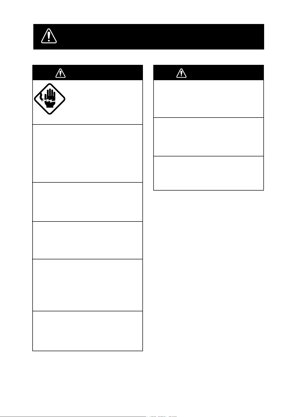
SAFETY INSTRUCTIONS
WARNING
WARNING
WARNING
ELECTRICAL SHOCK HAZARD
Immediately turn off the power at the
switchboard if water leaks into the
equipment or something is dropped in
the equipment.
Continued use of the equipment can cause
fire or electrical shock. Contact a FURUNO
agent for service.
Do not disassemble or modify the
equipment.
Fire, electrical shock or serious injury can
result.
Do not open the equipment.
Only qualified personnel
should work inside the
equipment.
WARNING
Keep heater away from equipment.
A heater can melt the equipment’s power
cord, which can cause fire or electrical
shock.
Use the proper fuse.
Fuse rating is shown on the equipment.
Use of a wrong fuse can result in equipment
damage.
Do not operate the equipment with wet
hands.
Electrical shock can result.
Do not place liquid-filled containers on
the top of the equipment.
Fire or electrical shock can result if a liquid
spills into the equipment.
Immediately turn off the power at the
switchboard if the equipment is emitting
smoke or fire.
Continued use of the equipment can cause
fire or electrical shock. Contact a FURUNO
agent for service.
Make sure no rain or water splash leaks
into the equipment.
Fire or electrical shock can result if water
leaks in the equipment.
iiiiiiiiiiiii
i
Page 4
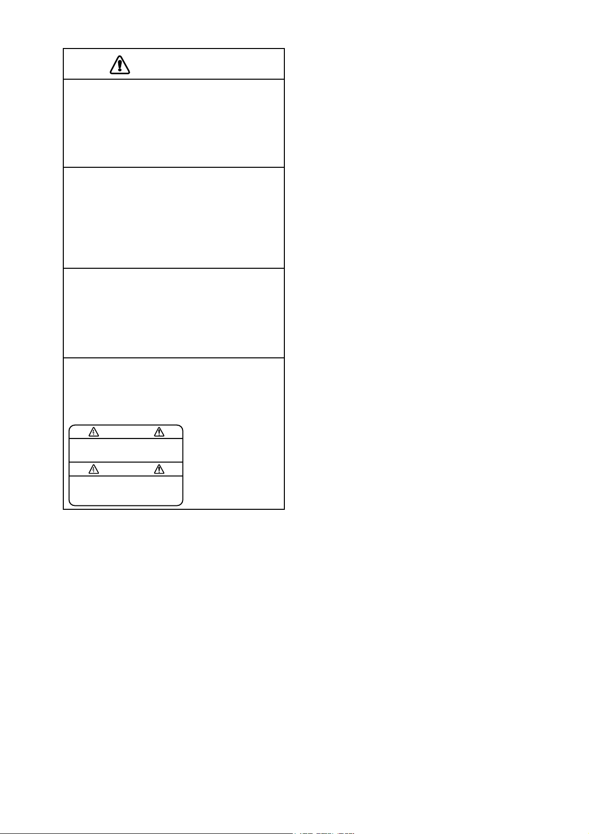
CAUTION
CAUTION
Do not exceed 18 knots when operating
the equipment and do not exceed 16
knots when lowering or raising the
transducer.
The transducer may become damaged.
The zinc block attached near the
transducer must be replaced yearly.
The junction between the transducer and
main shaft may corrode, which can result
in loss of the transducer or water leakage
inside the ship.
Do not use the equipment for other
than its intended purpose.
Use of the equipment as a stepping stool,
for example, may result in personal injury
or equipment damage.
A warning label is attached to the equipment. Do not remove the label. If the
label is missing or damaged, contact
a FURUNO agent or dealer.
WARNING
To avoid electrical shock, do not
remove cover. No user-serviceable
parts inside.
Name: Warning Label (1)
Type: 86-003-1011-0
Code No.: 100-236-230
ii
Page 5

TABLE OF CONTENTS
1. FOREWORD _________________________________________ 1
2. SYSTEM CONFIGURATION_____________________________ 2
3. CONTROLS _________________________________________ 3
Operating Controls .......................................................................................................... 3
Main Panel .......................................................................................................................4
Control Box Panel ...........................................................................................................5
Menu Screen .................................................................................................................... 7
4. BASIC OPERATION __________________________________ 10
General .......................................................................................................................... 10
Turning the Power On/Off.............................................................................................10
Lowering the Transducer............................................................................................... 11
Selecting a Display Range .............................................................................................11
Setting the Tilt Angle ..................................................................................................... 11
Adjusting the Gain......................................................................................................... 15
5. FINE TUNING THE PICTURE___________________________ 16
General .......................................................................................................................... 16
Eliminating Unwanted Feeble Echoes...........................................................................16
Displaying Surface Fish Clearly.................................................................................... 17
Suppressing Seabed Tail ................................................................................................17
Suppressing Seabed and Sea Surface Reflections in Shallow Fishing Grounds ........... 18
Rejecting Sonar Interference and Noise ........................................................................ 18
Selecting Horizontal Beamwidth................................................................................... 19
Selecting Vertical Beamwidth........................................................................................ 19
6. ADVANCED OPERA TION______________________________ 20
General .......................................................................................................................... 20
Measuring Range and Bearing to a Target.....................................................................20
Detecting Fish Schools Aurally .....................................................................................20
Relocating Fish School for Easy Observation ...............................................................21
Finding Fish School Center ........................................................................................... 22
Registering F1/F2 (function) key and Recalling ........................................................... 22
7. MARK AND DATA____________________________________ 24
Marks .............................................................................................................................24
Data................................................................................................................................25
8. INTERPRETING THE DISPLAY _________________________ 26
General .......................................................................................................................... 26
Interpreting the Display .................................................................................................26
iii
Page 6

9. WARNING __________________________________________ 30
Overvoltage W arning.....................................................................................................30
Unretracted Transducer Warning................................................................................... 30
10. MENU ____________________________________________ 32
General .......................................................................................................................... 32
Changing Menu Settings ............................................................................................... 32
11. INTERFACE MODULE CSH-5060 ______________________ 35
Specifications................................................................................................................. 35
Operation .......................................................................................................................36
Indications .....................................................................................................................47
Marks and Data.............................................................................................................. 51
Event Mark Position Output ..........................................................................................52
12. MAINTENANCE ____________________________________ 53
General .......................................................................................................................... 53
13. UNIT DIAGNOSTIC TESTS ___________________________ 54
Description of Unit-diagnostic Tests .............................................................................54
14. CHARACTERISTICS OF THE ULTRASONIC WAVE IN
WATER___________________________________________ 58
Sound Velocity...............................................................................................................58
Absorption and Attenuation........................................................................................... 59
Refraction ......................................................................................................................60
Adverse Effect of Air Bubbles....................................................................................... 61
Reflection at Seabed and Fish School ........................................................................... 62
SPECIFICATIONS____________________________________ SP-1
INDEX
iv
Page 7

1. FOREWORD
The FURUNO CSH-5 MARK-2 Color Scanning Sonar is a fullcircle,multibeam electronic scanning sonar which detects and instantaneously displays fish schools and underwater conditions in 16 colors
on a 14" non-glare, high resolution CRT screen. Its ease of operation,
versatility and compact size make it the perfect match for any class
of fishing vessel.
Some of the prominent features of the CSH-5 MARK-2 are as follows;
• Compact 8" tube retraction tank
• V ivid 16-color display greatly improves recognition of seabed, and
concentration, distribution and volume of fish schools.
• Various on-screen indications keep operator abreast of fishing conditions.
• Change of control setting is indicated by displaying the new setting in larger characters for five seconds.
• High power MOS FET transmitter ensures reliable operation under any condition.
• Control box, for operation from a distance.
The CSH-5 MARK-2 is a highly sophisticated instrument which performs its intended functions only when operated properly . Please carefully read and follow the recommended procedures for operation and
maintenance to take full advantage of the many features this unit has
to offer.
1
Page 8

2. SYSTEM CONFIGURATION
System Configuration
2
Page 9
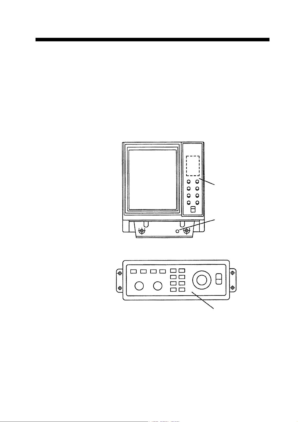
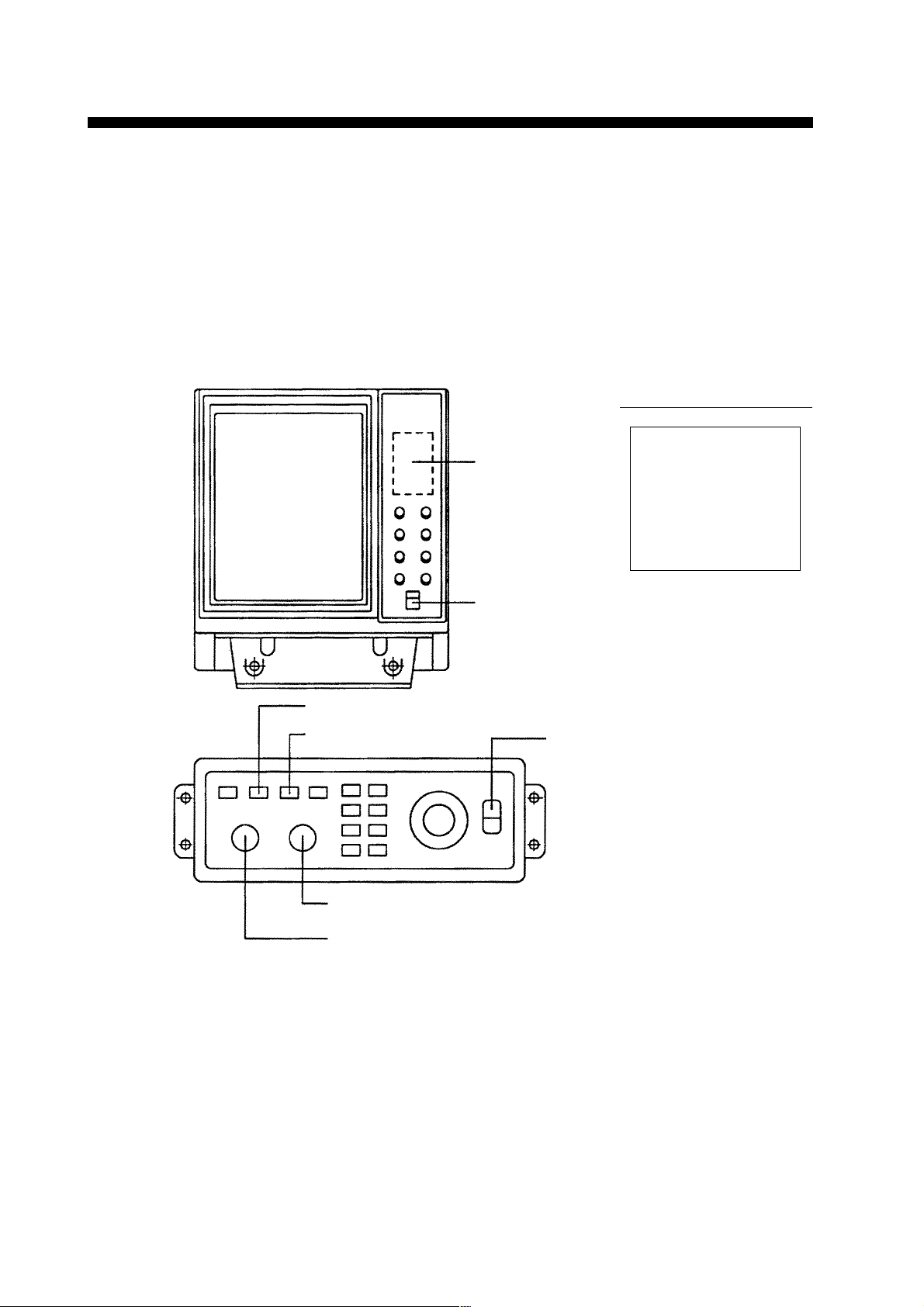
Operating Controls
The CSH-5 MARK-2 provides intuitive operation. If you change a
control setting you will see the associated reaction on the screen almost immediately . All operations are carried out from the main panel
and the control box. The front panel incorporates mainly controls
which do not require frequent adjustment, such as brilliance, interference rejector, and audio volume. The control box, which is connected
to the display unit via a 7 m-long connection cable, houses the mostoften used functions, including transducer operation controls, and
range and gain controls.
3. CONTROLS
DISPLAY UNIT
CONTROL BOX
Main Panel
DEMAG Button
demagnetizes the
display for cleaning
irregular picture color.
Control Panel
3
Page 10
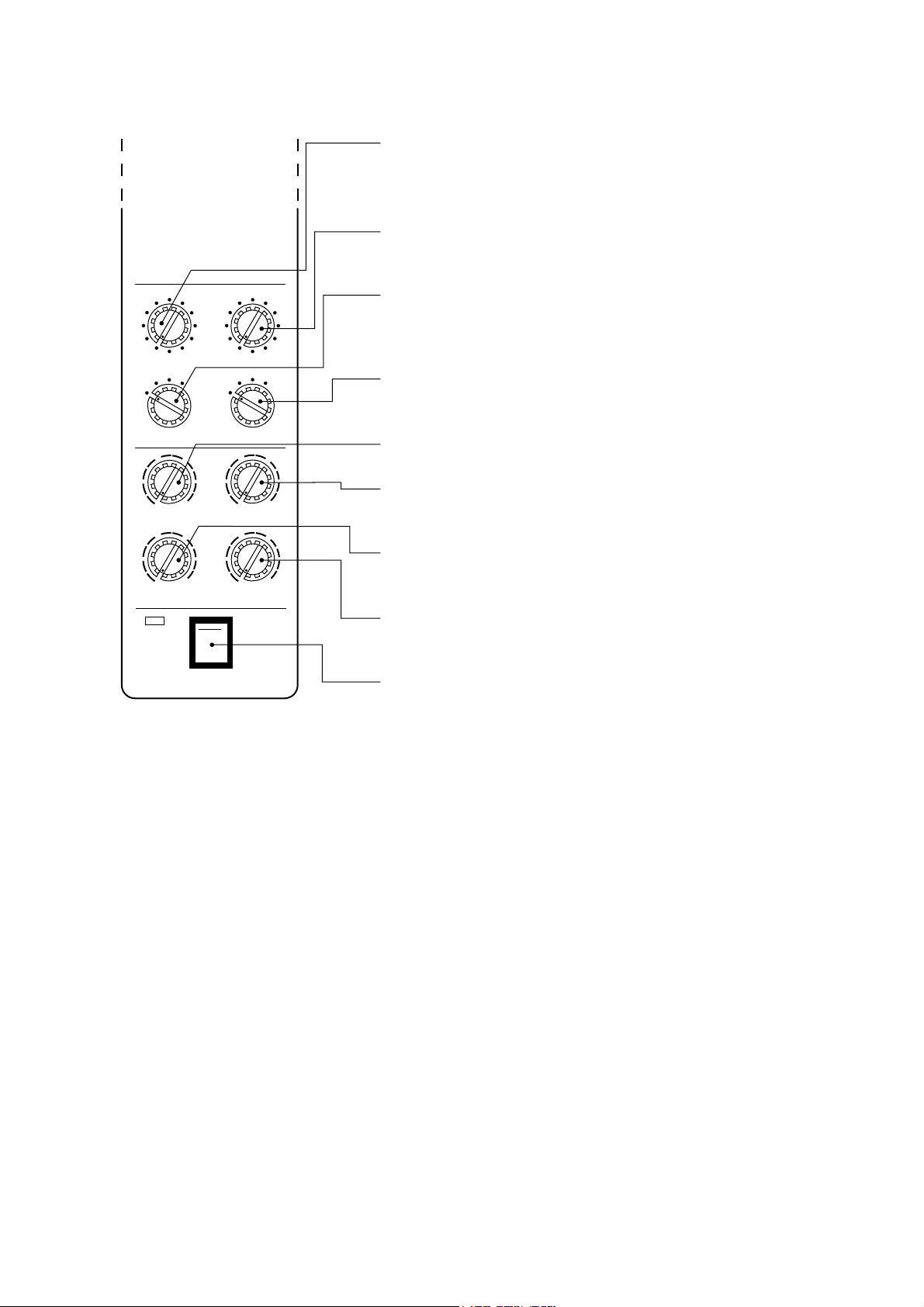
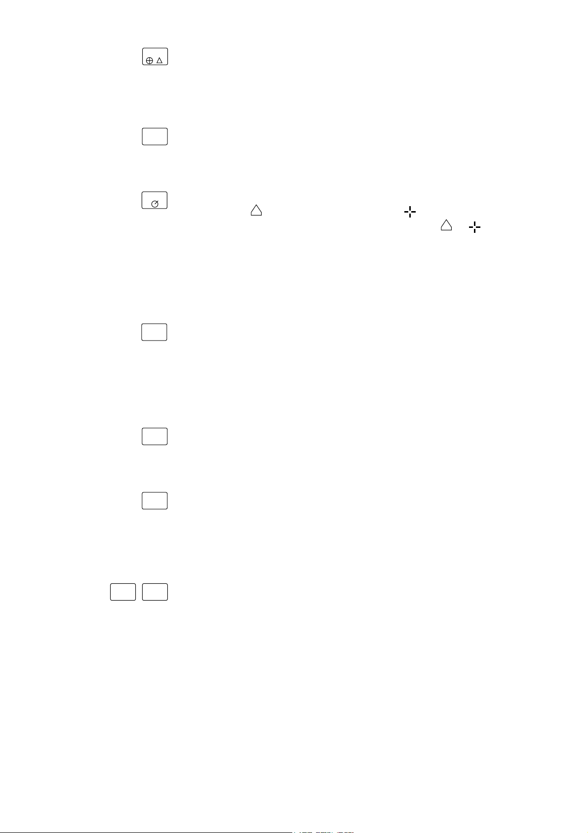
Main Panel
AGC suppresses the echo tail of strong targets, e.g., the
seabed, for easy recognition of fish schools adjacent to the sea
bottom. Position "1" or "2" is the normal setting.
NOISE LIM is used to reject noise which is displayed over the
screen in light blue. Position "3" is the normal setting.
6
3
6
6
8
8
8
4
2
0
NOISE LIM
1
OFF
4
2
0
CONTRAST
4
2
0
AUDIO
ON
OFF
6
10
2
3
IR
6
10
6
10
2
OFF
2
2
4
0
AGC
2
1
VP
4
0
BRILL
4
0
DIMMER
POWER
10
10
10
COLOR SCANNING SONAR
VP (Video Processor) adjusts the after-image of the echoes for
8
proper period; echoes are stretched in the radial direction. Set
at "1" for ordinary use.
IR (Interference Rejector) rejects random noise and
interference caused by other echo sounders or sonars.
BRILL adjusts brightness of the screen in eleven steps.
8
CONTRAST adjusts the range of brightness between
highlights and shadows on the produced image.
8
DIMMER adjusts panel (main panel and control box panel)
illumination.
AUDIO controls the volume of the built-in loudspeaker for
monitoring a target echo appearing the bearing mark.
POWER switches on and off the entire system.
Note:
When the power is turned off before r etracting the transducer,
the transducer is automatically retracted. However, for safety
purposes, do not forget to retract the transducer before turning the power off.
4
Page 11
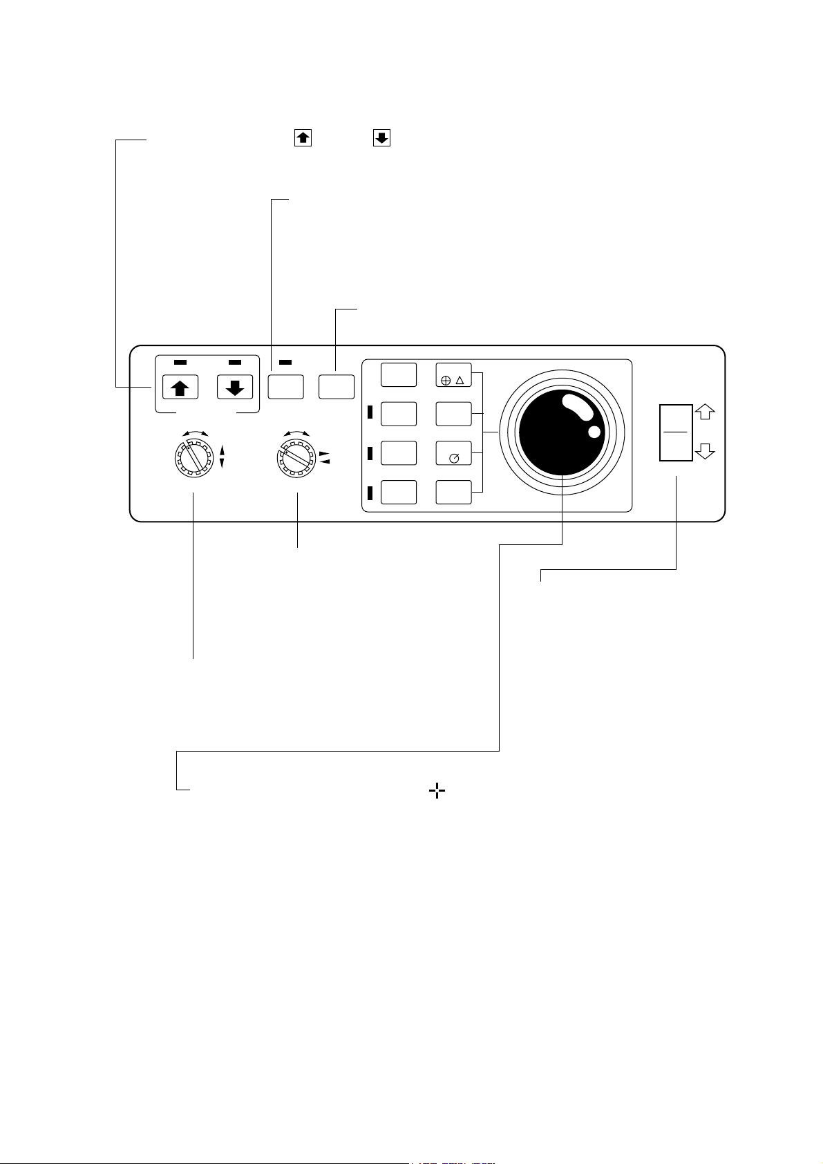
Control Box Panel
TRANSDUCER retracts and lower the transducer. The lamp above the switch flickers while
the transducer is moving and lights when stopped.
TX turns on the transmitter, freeze the display and turns off the
transmitter. The light above the switch is on when the transmitter is turned on
and flickers when off.
Note: The transmitter is turned off when the transducer is retracted even if
the light above the TX switch is on.
MENU turns the menu display on and off.
TRANSDUCER
RANGE
AUTO
MENUTX
TILT
SECTOR
SCAN
-+-+
F1
GAIN
F2
EVENT
EVENT
DELETE
R/B
OFF-
CENTER
GAIN adjusts the receiver sensitivity.
Adjust it for clear presentation of fish
school echoes. This control is also
used to change settings on menu
screens.
RANGE selects a picture display range. This control is
also used to select items on menu screens. Note that
this control endlessly turns in both directions.
TILT
TILT continuously varies the tilt
angle of the sounding beam
between 0° and - 55°. The operating
angle is always indicated on the
screen.
TRACKBALL moves the trackball mark ( ) to a desired position. The trackball
mark data, i.e., slant range, horizontal range, depth and bearing to the mark, are
always indicated on the screen. Additionally, this control is used to position the
own ship’s mark, enter event marks and set the alarm.
5
Page 12
EVENT
EVENT displays the latest event mark “ + ” and its position data; i.e.,
horizontal range, depth and bearing measured from own ship’ s position. (optional interface board is required to use this function.)
EVENT
DELETE
R/B
OFF-
CENTER
To delete event mark, locate the cursor on a event mark you want to
delete and press EVENT DELETE key.
R/B draws a straight line, called Bearing Mark, from own ship position mark “
draws a circle called Range Mark with a radius of
” toward the trackball mark “ ” and simultaneously
to . Range
and bearing data of the intersection of the two marks are displayed on
the lower center of the screen. T o turn off the range and bearing marks,
move the trackball mark near the own ship position mark and press
the R/B key.
OFF-CENTER moves the own ship’s mark to a desired location on
the screen in steps of 1/6 of screen radius. To off center the screen,
place trackball mark on location to offcenter and press the OFF-CEN-
TER key. To reset the off-centered own ship’ s mark, press the OFF-
CENTER key again.
AUTO
TILT
SECTOR
SCAN
F1 F2
AUTO TIL T automatically tilts the sounding beam up and down within
the tilt angle set on the menu screen.
SECTOR SCAN scans the bearing mark in 2° steps within the area
selected on the menu screen. The echoes along the marker can be
monitored thru the built-in speaker. The lamp at the left of the switch
lights during sector scanning.
These keys provide user-defined sonar setting by one key operation.
These keys have factory settings. See page 22.
6
Page 13
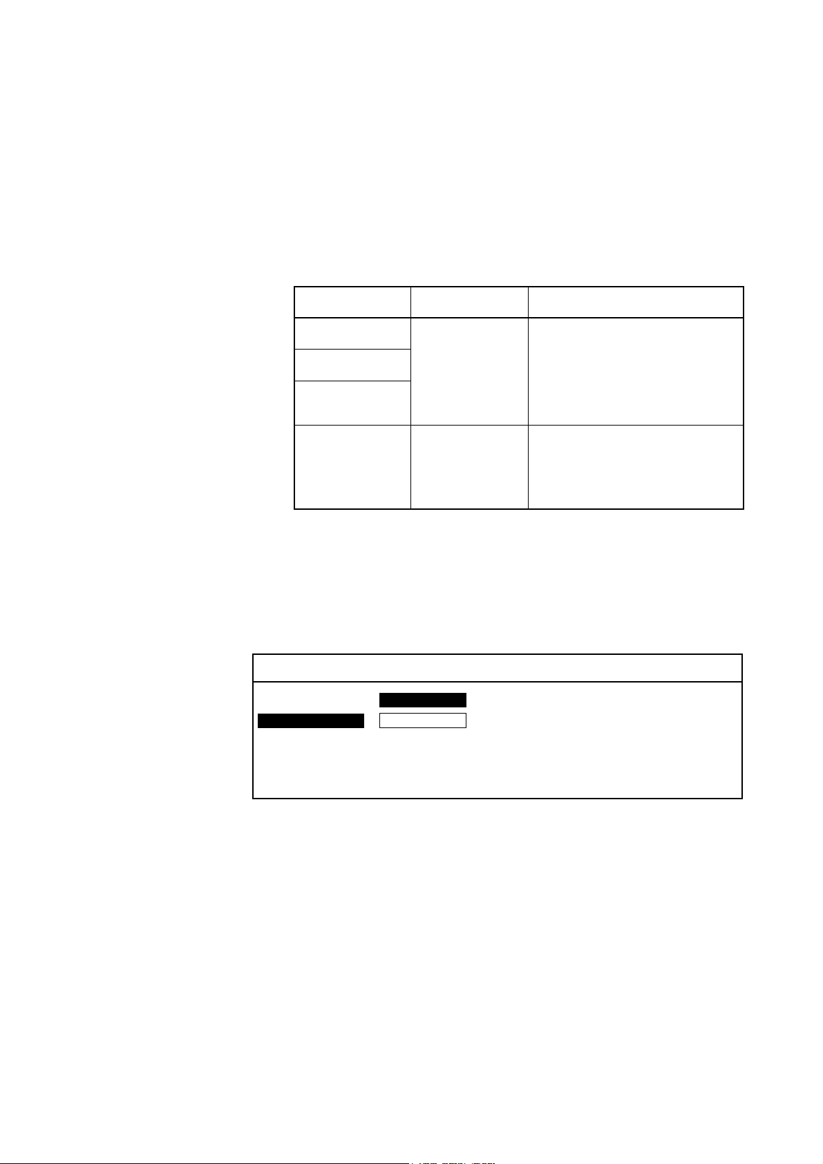
Menu Screen
The CSH-5 MARK-2 employs four menu screens; menu-l, menu-2
and system menu. Of the four menus, the menu-2 and system menu
contain preset items which do not require setting alteration if they are
once set at installation. See page 32 for further details. The menu-l
contains items to be set by the operator while using the sonar, taking
the fishing ground and fishing method into account. This menu can
be recalled on the lower part of the screen as “scan menu” during
normal operation. This let you adjust setting while observing the sonar picture.
noitacilppAesuotwoH
1-UNEM
2-UNEM
METSYS
UNEM
UNEMNACSgnittesresuroF
metsysroF
gnittes
.erutcip
smetitceleS.noitarugifnoc
.rettimsnartehtffogninrut
ybneercsunemehtllaceR
ehttsujdadnayekUNEM
Recalling Scan Menu
Press the MENU key , and 5 lines of the menu items are displayed on
the lower part of the screen. Note that the scan menu can be recalled
only when the transmitter is on.
SCAN MENU
**
HUE : 1 234
TX OUTPUT :8
PULSELENGTH : 7
TX CYCLE : 10
TVG NEAR : 6
**
( RANGE SW : U/D GAIN SW : L/R )
hcaetceles,noitallatsniretfA
metsysruoyotgnidroccameti
rorecudsnartehtgnisiarretfa
ranosytilauqtsebehtrofmeti
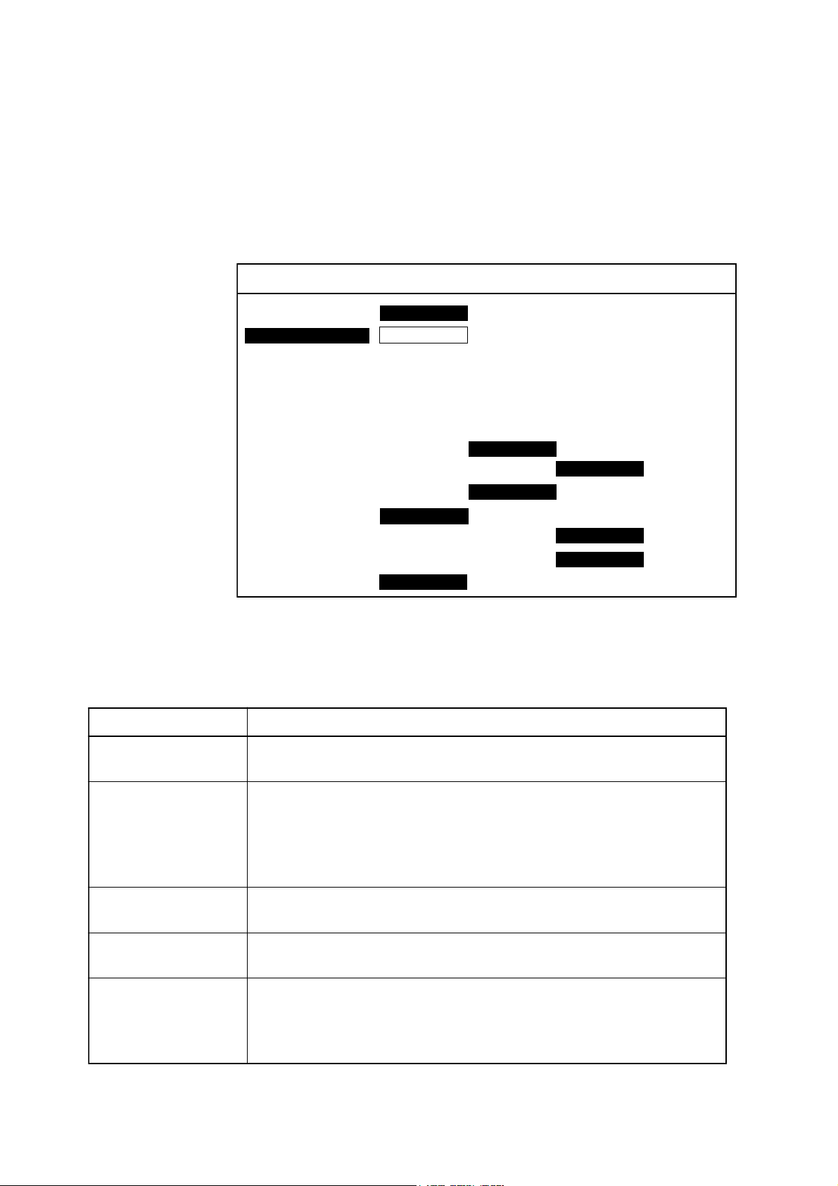
Changing Setting
T o change a setting, select item with the RANGE control and setting
with the GAIN control. The selected item is highlighted in green and
the selected setting is circumscribed in white. T o scroll the menu items,
turn the RANGE control counterclockwise.
Note:
The gain and range of the sonar picture can not be changed
while the scan menu is displayed.
7
Page 14
Turning Off Scan Menu
To turn off the scan menu, press the MENU key.
Note:
Settings for the items shown in red are locked. To unlock the
settings, call up the system menu. See page 33.
List of Scan Menu Items
SCAN MENU
**
HUE : 1 234
TX OUTPUT :8
PLUSELENGTH : 7
TX CYCLE : 10
TVG NEAR : 6
TVG FAR : 7
AUTO SCN WDTH : ± 10° ± 20° ± 40°± 60°
AUTO TLT WDTH : ± 2°~10°± 4°~14° ± 6°~20° ± 10°~26°
HOR BEAM ANGL : WIDE NARROW
VER BEAM ANGL : WIDE NARROW
RES COL CURVE : LINER 1 2 3
COL EMPHASIS : 1 (LOW) 2 3 4 (HIGH)
FUNC KEY PROG : FUNC1 FUNC2 FACTORY
**
( RANGE SW : U/D GAIN SW : L/R )
Contents of Scan Menu
METIUNEMGNINAEM
EUH otyalpsidehtfosrolocdnuorgerofdnadnuorgkcabehtsegnahC
TUPTUOXT rewopmuminimrofsi"0";spetsnevelenirewoptuptuostsujdA
HTGNELESLUP ehtrofsi"0";spetsnevelenihtgneleslupnoissimsnartasteS
ELCYCXT ehtrofsi"0";spetsnevelenietarnoititepernoissimsnartstceleS
RAENGVT
RAFGVT
.snoitidnocgnithgilrofetasnepmoc
wolaesudna,esulamronrof"01"otteS.mumixam,"01"dna
hsifserucsboohcedebaesronoitcelferecafrusaesnehwrewop
ehttahtetoN.snoitareporetawwollahsdnaegnartrohsnisloohcs
.degnahcsignittesehtretfasdnoces01segnahcrewoptuptuo
.tsegnoleht"01"dnahtgneltsetrohs
.tsetrohsehtrof"01"dnadoireptsegnol
,segnargnoldnatrohstaytivitisnesreviecerehtlortnoC
.ylevitcepser
.gnitteslamronehtsi"5"noitisop,m004revO:RAF
.gnitteslamronehtsi"5"noitisop,m004nihtiW:RAEN
8
Page 15

NACSOTUA
HTDIW
HTDIWTLITOTUA ;)seergedni(htdiwtlitcitamotuaehttesotdesusiunemsihT
± -2 ± ,01 ± -4 ± ,41 ± -6 ± ro,02 ± -01 ± nisrebmunowtehT.62
LGNAMAEBROH ediwtceleS.elgnamaeblatnozirohehttcelesotdesusiunemsihT
LGNAMAEBREV rofediw;esularenegrofworrantceleS.elgnamaeblacitrevehtsteS
.ylediw
;htdiwnacsehtsteS ± ,01 ± ,02 ± ro04 ± ediwaesU.)seergedni(06
ecnotigniworran,aeranacsafohcraeslarenegatcudnocothtdiw
.detcetedsiloohcshsifa
esuniegnarehtsasegnahchtdiwehttahtswohsgnitteshcae
ehtrofenothgirdnaegnartsegnolehtrofrebmuntfel;segnahc
.egnartsetrohs
.noitanimircsidgniraebrettebrofworran;esularenegrof
ediwehttahtetoN.deepshgihatanwoddnapusmiwshcihwhsif
noitcetedhsiftubyllacitrevaeraediwahcraesotswollaelgnamaeb
oslaetoN.sdaerpsrewopdettimsnartehtecnisdenetrohssiegnar
deyalpsidsiohcemottobeht,retawwollahsanidesunehw,taht
EVRUCLOCSER
roloCesnopseR(
)evruC
.noitisopRAENILsignittes
SISAHPMEROLOC ;yalpsidrolocehtniderfonoitroporpehttesotdesusiunemsihT
.derni
GORPYEKCNUF 2Fdna1Frofgnittesdenifed-resuretsigerotdesusiunemsihT
.gnittestluafedtesotsiYROTCAF.syek
seirav)deyalpsidhtgnertsohce(tuptuo,noitisopRAENIL
ehtnI.seohcegnortsdnakaewneewtebecnalabehtstesunemsihT
rehgihatceleS.)htgnertsohcelautca(tupnihtiwyllanoitroporp
deyalpsideraseohcekaew:seohcekaewezisahpmerettebotgnittes
dradnatsehT.rehgihseogrebmunehtsasrolocohceregnortsni
deyalpsideraseohcenoitroporpretaerg,rehgihseogrebmunehtsa
9
Page 16
General
4. BASIC OPERATION
This section provides information necessary for basic operation of
the CSH-5 MARK-2, from turning the power on and off to detecting
and tracking fish schools. The basic operating procedure is shown
below.
Basic Operating Procedure
CONTROL SETTINGS
OUTPUT 10
Location for
magnetic function
card
PL 10
TVG, (Far, Near) 5, 5
AGC 0
NOISE LIM 3
VP 1
IR OFF
2/7 Lower/raise transducer.
4 Turn transmitter on.
6 Adjust gain.
3 Select display range.
Turning the Power On/Off
1/8 Turn power ON (OFF).
5 Set tilt angle.
Power On
Press the POWER switch on the main panel. The lamp at the left of
the switch lights.
Note:
The Display and the Transceiver are checked for proper operation each time the power is applied. The check is explained
in greater detail in a later chapter.
10
Page 17
Power Off
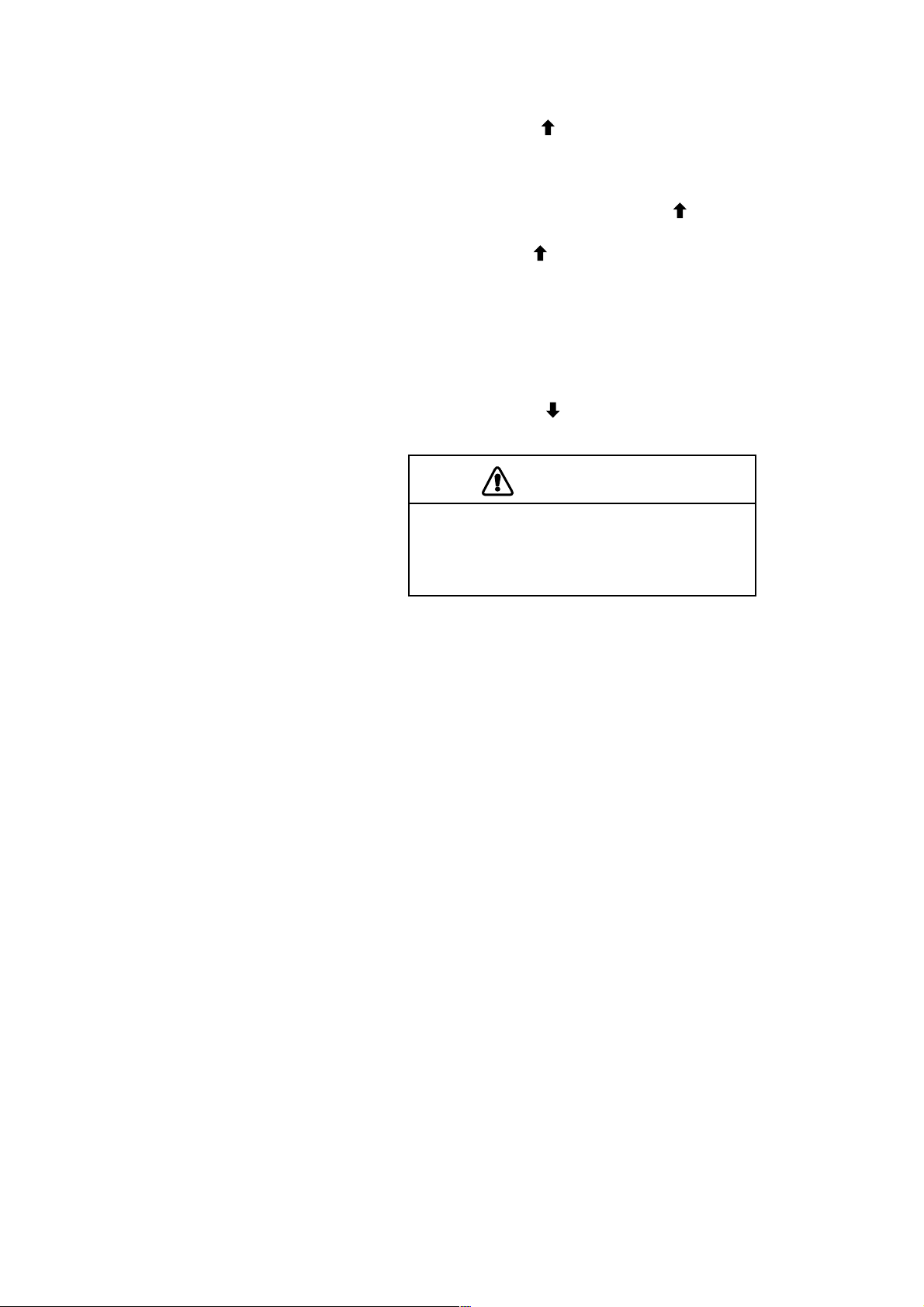
CAUTION
Press the TRANSDUCER “ ” switch on the control box. W ait until
the lamp above the switch lights, and then press the POWER “OFF”
switch. Note that the transducer automatically retracts into the tank
even if the POWER “OFF” switch is pressed without raising the
transducer (by pressing the TRANSDUCER “ ” switch). However,
for safety purposes, it is recommended that you make a habit of pressing the TRANSDUCER “
ducer is retracted.
Lowering the Transducer
Press the TRANSDUCER “ ” switch. The lamp above the switch
flickers, and then lights when the transducer is fully lowered.
” switch first to ensure that the trans-
CAUTION
Observe maximum allowable ship’s
speed of 18 knots during operation and
16 knots while raising/lowering
transducer.
Selecting a Display Range
The RANGE switch on the control box is used to select a display
range. The range selected is displayed at the top center of the screen.
Setting the T ilt Angle
The tilt angle shows the direction to which the sound wave is emitted. When the sound wave is emitted horizontally , it is said to be zero
(0) degrees and when emitted vertically , 90 degrees. T o set a tilt angle,
operate the TILT lever for the desired angle while watching the tilt
angle indication at the top right-hand side of the screen. The tilt angle
can be set in one-degree steps within the range of 0 to 55 degrees.
Finding the proper tilt angle is of utmost importance when searching
for fish. This unit, because of its compact size, is highly suited to
coastal water fishing where the depth of the main fishing ground is
from 50-l00 m. In this type of fishing ground it is imperative that the
seabed echo be always displayed to properly distinguish between fish
and the seabed. When selecting a tilt angle, keep the following points
in mind.
11
Page 18

Seabed Echo vs Tilt Angle
Case 1: Tilt Angle 30 to 40 degrees
A wide tilt angle will display the entire seabed since it is captured by
the full width of the beam.
Case 2: Tilt Angle 10 to 20 degrees
A narrow tilt angle will display only half the seabed since it is cap-
tured by only the lower half of the beam.
Case 3: Tilt Angle 0 to 10 degrees
An exceptionally narrow tilt angle may or may not capture the sea-
bed since the returning echo is weak.
Example of How to Discriminate Fish Echoes
from the Seabed
The following figure illustrates how two fish schools a and b are
displayed on screen using three different tilt angles.
Case 1: Tilt angle 30 to 40 degrees
Fish school is obscured by the seabed.
Case 2: Tilt angle 10 to 20 degrees
Fish school is located above the seabed (midwater).
Case 3: Tilt angle 0 to 10 degrees
Fish school is located close to the seabed.
Case 1 Case 2 Case 3
b
Fish School a
Seabed
a
Seabed
a
Fish School a
a
Fish School a
Seabed
b
Case 1 Case 2 Case 3
12
Page 19
Points to Consider
• As a general rule of thumb, a vertically distributed fish school is a
better sonar target than the seabed, since it reflects the transmitted
pulse back toward to the source.
• In case 3, both fish schools a and b are presented. Generally
speaking, however, midwater fish schools tend to be larger than
bottom fish schools and they are often displayed near the seabed
on the sonar screen.
• Detection of bottom fish is difficult if they are not distributed ver tically.
Tilt Angle for Surface Fish
Sound emitted from the sonar transducer forms a circle-shaped beam
with a width of approximately 13 degrees in the vertical direction
(vertical beam width). The tilt angle is indicated by the angle between the center line of the beam and the horizontal plane. Then, if
the tilt angle is set to 0 degrees, the center line is parallel with the sea
surface and one half of the emitted sound goes upward toward the sea
surface.
This causes a half of the emitted sound to be reflected back toward
the transducer and displayed on the screen as sea surface reflections.
When the sea is calm, since the sound is reflected just like a light
hitting a mirror at a narrow incident angle, it propagates away and the
sea surface reflections become negligible.
However if the sea is not calm enough, they will become dominant
and will interfere with observation of wanted echoes. To minimize
these sea surface reflections and to search surface fish schools effectively, the tilt angle is usually set to 5-6 degrees so that the upper
portion of the beam becomes almost parallel with the sea surface.
When the sea is rough, it is often set to a little larger angle.
SEA SURFACE SEA SURFACE
TILT 0°
13°
TILT 7°
13°
Suitable Tilt Angle
The figure on the next page illustrates the relationship among tilt
angle, depth and detection range. Refer to it to find out the suitable
tilt angle for a given depth/detection range.
13
Page 20
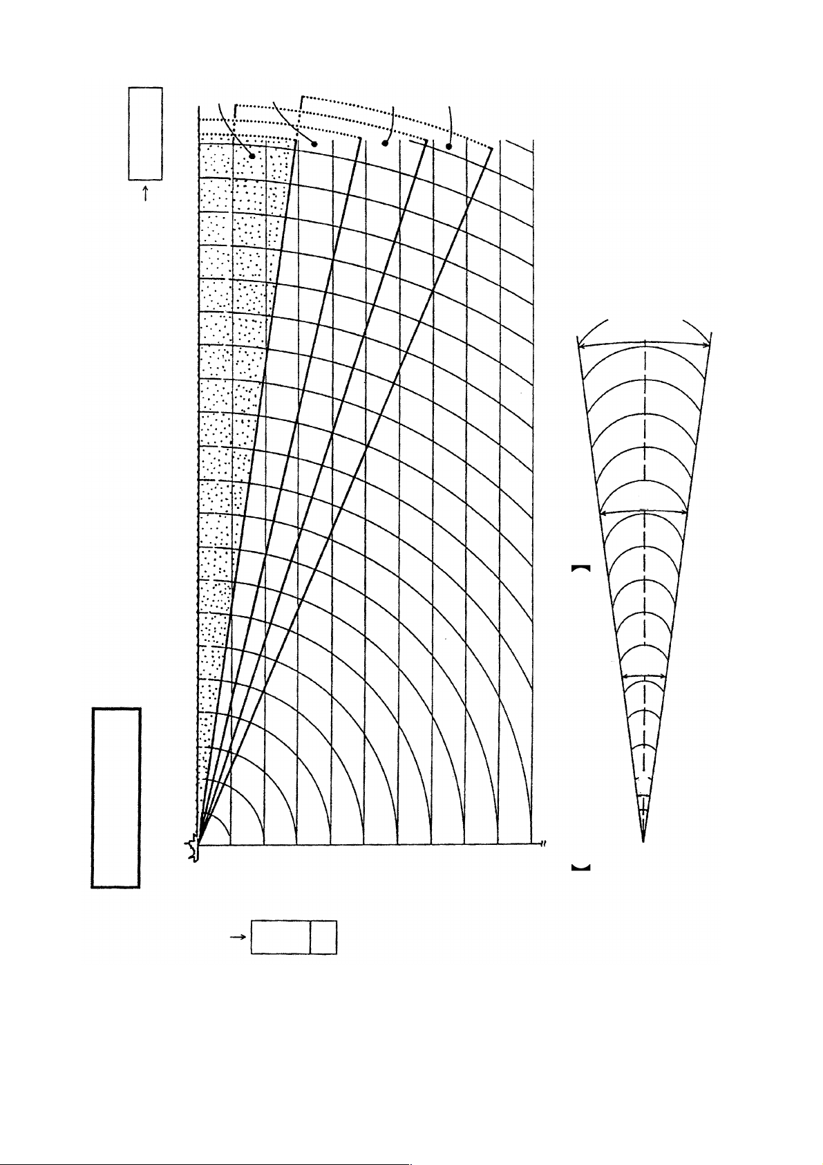
m
Range
0°
5°
10°
15°
68m
300m
Tilt angle vs. Beam Coverage
100 (200) 200 (400) 300 (600) 400 (800)
TIL T ANGLE
20 (40)
40 (80)
60 (120)
80 (160)
100 (200)
46m
200m
23m
100m
13°
Vertical Width of Sonar Beam
200 (400)
Depth
m
14
Page 21

Adjusting the Gain
The gain should be adjusted to see fish echoes clearly with minimal
noise on the screen. Too high a setting not only causes excessive
noise on the screen and makes it difficult to discriminate wanted fish
echoes but also causes seabed echoes to be painted in strong colors,
resulting that the echoes from bottom fish are masked by seabed reflections. Normally, positions “3” thru “7” are used.
Gain Low Gain Proper Gain High
15
Page 22
5. FINE TUNING THE PICTURE
General
In the previous chapter basic operation of the sonar was presented.
This chapter describes the procedures for fine tuning the sonar picture.
Eliminating Unwanted Feeble Echoes
Echoes from targets such as seabed and fish return to the transducer
in order of distance to them, and when we compare their intensities at
the transducer face, those from nearer targets are generally stronger
when their reflecting properties are nearly equal. The sonar operator
will be quite inconvenienced if these echoes are directly displayed on
the screen, since he can not judge the actual size of the target from
the size of echoes displayed on the screen. T o overcome this inconvenience, the TVG function is incorporated. It compensates for propagation loss of sound in water; amplification of echoes on short rang is
suppressed and gradually increased as range increases so that similar
targets are displayed in the similar intensities irrespective of the ranges
to them.
The CSH-5 MARK-2 incorporates two TVG function, NEAR and
FAR, and they mainly compensate for propagation loss on short and
long ranges respectively , centered at the ranges shown below. Setting
a TVG in the scan menu larger (smaller) increases (decreases) amplification of echoes.
NEAR
400m
The TVG is also used to suppress unwanted echoes and noise which
appear in a certain range area on the screen such as sea surface reflections and cruising noise. To obtain the proper TVG setting, follow
the procedure below.
FAR
TVG Setting Procedure
1. Set the TVG menus NEAR to “5” and FAR to “5”. These are the
standard setting and you can maintain these settings in most cases.
2. When sea surface reflections or plankton layers disturb the pic-
ture, adjust the NEAR control to eliminate them. They will be
eliminated by decreasing the control setting by “1” or “2”.
16
Page 23

3. Locate a fish school on a long range setting which is approaching
own ship. Note that the tilt should be kept adjusted so that the fish
school is always placed in the center of the sonar beam, i.e., so
that the fish school is displayed in strongest colors possible. Check
that the fish echo is displayed in the same color while it approaches.
If the color changes suddenly to weaker colors as the fish echo
enters FAR and NEAR areas, the TVG is improperly set. Adjust
the TVG in the scan menu to correct it. If this again produces sea
surface reflections and noise, try to remove them with the AGC
and NL controls as described later on.
Displaying Surface Fish Clearly
When you are searching for surface fish with the tilt set to a narrow
angle, sea surface reflections may disturb or mask wanted fish
echoes. In this case, in addition to the TVG adjustment described
earlier adjust the AGC control between positions “0” thru “3”.
Suppressing Seabed Tail
As noted earlier, fish schools (echoes) located near the seabed are
sometimes difficult to detect because you have to discriminate them
in the seabed reflections. The AGC control and PULSELENGTH in
the scan menu, if used properly, decrease the tail of seabed reflections, making it easier to discriminate bottom fish.
AGC Control
The AGC control functions to automatically reduce the receiver gain
only against strong echoes such as the seabed or a large fish school.
Since weak echoes remain unaffected, a small fish school becomes
easier to detect. Adjust it so that the AGC works only on seabed re-
flections. Do not turn it too far clockwise.
PL (Pulselength)
The pulselength control determines the length of the transmission
pulse emitted into the water. While a longer pulse is advantageous
for long range sounding, it has the disadvantage of being poor in
discrimination of targets, i.e., ability to separate several closely located targets. When searching bottom fish, therefore, it is useful to
shorten the pulselength in order to separate fish echoes from seabed
reflections. Decrease the PL setting to shorten the pulselength in the
scan menu. For search of surface and midwater fish in which seabed
reflections are not so strong, the longest pulselength “ 10” should be
used.
17
Page 24

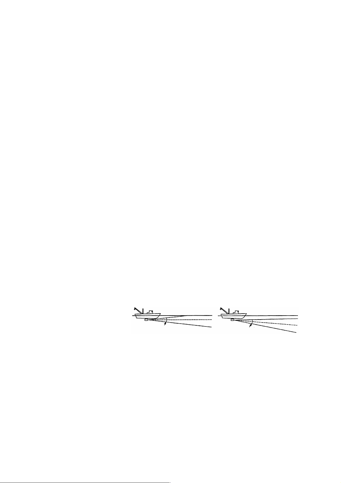
Suppressing Seabed and Sea Surface Reflections in Shallow Fishing Grounds
In shallow fishing grounds with hard or rocky bottom, seabed reflections often interfere with wanted fish echoes and they can not be
eliminated sufficiently with the aforementioned TVG and AGC controls, especially when the TILT is set to a larger angle in order to
track fish schools approaching within 400 m. In such cases try to
reduce the output power by setting the OUTPUT in the scan menu
without turning down the gain. The picture becomes clearer when
output power is reduced rather than when the gain is decreased as
illustrated below.
Fish echo
No Good
Good
TVG & AGC adjusted
with OUTPUT
maintained high
OUTPUT decreased
with gain maintained
constant.
Rejecting Sonar Interference and Noise
While observing the sonar picture, you may encounter occasional or
intermittent noise and interference as shown below . These are mostly
caused by on-board electronic equipment, engine or propeller noise,
or electrical noise from other sonars being operated nearby.
Fish echo
weakened
Fish echo
Identifying Noise Source
To eliminate noise effectively, you should first identify the noise
source.
* T urn off the TX switch on the control box and operate all on board
equipment one by one while observing the picture.
* Run the boat at various speeds to check if the noise is speed de-
pendent.
If neither of the above two steps has effect on the picture, adjust the
IR (Interference Rejector) and NOISE LIM (noise limiter) controls
as follows.
18
Page 25

Rejecting Noise with IR Control
This control is similar to the interference rejector on echo sounders
and radars. It is effective for rejecting random noise and sea surface
reflections in rough sea conditions. Set the IR control to positions
“1” thru “3” so that noise is just eliminated. Do not use an unnecessarily high setting since it may also reject small wanted echoes.
Rejecting Noise with NOISE LIM Control
W eak, unwanted reflections, colored light blue or green, are displayed
when water is contaminated or plankton layers exist or due to ship’s
noise. These echoes gradually become bluish as the NOISE LIM control is turned clockwise. Usually position “3” to “4” is used.
Rejecting Interference with TX Cycle
When other sonars operate nearby at the same transmission interval
as that of own ship’s sonar, interference ring caused by other sonars
are displayed. To erase the interference ring from the screen, reduce
the TX cycle setting on the scan menu screen. See page 8.
Note:
When the sonar is used in a shallow water with the range set
between 100 m and 200 m and the TX cycle at “10”, seabed
reflections caused by the transmission which is the last but
one on near range on screen. Reduce the figur e of TX cycle to
“7” or “8” to reject them.
Selecting Horizontal Beamwidth
If you wish to have better bearing discrimination* for fish schools
and also wish to examine the contour of seabed, call up scan menu
and select “narrow horizontal beam width”.
Interference
* Ability to distinguish two closely located targets at the same range
and different bearings.
Selecting Vertical Beamwidth
When better detection range is required, call up scan menu and select
“narrow vertical beamwidth”.
19
Page 26

6. ADV ANCED OPERA TION
General
It this section, how to use the CSH-5 MARK-2 effectively in actual
fishing operations is presented.
Measuring Range and Bearing to a Target
To measure the range and bearing to a target, use the trackball.
Procedure
1. Operate the trackball to place the trackball mark “ ” on the target you want to measure the range and bearing. The range and
bearing are displayed at the left top on the screen.
Slant Range
Horizontal Range
Depth
bearing
Note:
The 360° or 180° indication system can be selected on the menu-2.
See page 33.
The bearing is shown in either 360° or 180° indication system
relative to the ship's heading. In the latter case, “B” is indicated as follows.
B P ------- on the port side
B S ------- on the starboard side
Detecting Fish Schools Aurally
Trackball Mark
Occasionally you will be preoccupied with other tasks and unable to
concentrate on watching the sonar picture. In such cases it would be
a good choice to use the audio function. This function enables you to
monitor echoes from fish schools and seabed through the built-in
speaker.
After you become accustomed to utilizing the audio function, you
should be able to detect a fish school from a range longer than you
can detect it on the screen.
20
Page 27

Procedure
1. Move the trackball mark “ ” to the direction you want to moni-
tor through the speaker, by operating the trackball.
2. Press the R/B key . The bearing marker will appear in the direction
of the trackball mark and echoes in that direction are monitored
through the speaker. Adjust the volume with the AUDIO control
on the front panel.
To cover a certain area, press the SECTOR SCAN key. The bear-
ing marker automatically scans in 2° steps starting from the bearing
set at step 2 to cover the selected sector, giving you audio in the directions of 2° steps.
T o change the coverage area call up scan menu, and then select an
auto scan width with the GAIN control; ±10°, ±20°, ±40°, ±60°.
To turn off the audio function, erase the bearing marker by placing
the trackball mark on own ship mark and then pressing the R/B key.
Trackball Mark
Bearing Marker
Auto Scan Width
Own Ship Mark
Relocating Fish School for Easy Observation
When a fish school is located near the edge of the screen and inconvenient for observation, use the off-center function to relocate the
fish school to the desired place on the screen.
Fish School
Off-center
"ON"
Fish School
Own ship Mark
Trackball Mark
Procedure
1. Move the trackball mark “ ” to the position where the own ship
mark is to be moved.
21
Page 28

2. Press the OFF-CENTER key on the front panel.
3. T o move the own ship mark back to the center of the screen, press
the OFF-CENTER key again.
Finding Fish School Center
When you want to find the center depth of a fish school, use the auto
tilt function which automatically scans the tilt angle within the selected width.
Procedure
1. Call up the scan menu, select the menu item “AUTO TL T WDTH”
and then choose a tilting width. The center tilt angle of the scanning is set by the TILT lever.
Both center and current tilt angles are displayed along with the range
data at the upper right corner on the screen.
R 800
T 8°
(10° )
Range
Angle set by TILT lever
Present tilt angle
Registering F1/F2 (function) key and Recalling
Function keys provide user defined sonar settings by one key operation.
Default setting
These keys are preset at factory for one key operation as follows;
F1 : For detection of near range
TX OUTPUT
PULSELENGTH
TX CYCLE
TVG NEAR
TVG FAR
HOR BEAM ANGLE
VER BEAM ANGLE
RES COL CURVE
COL EMPHASIS
(Factory setting)
8
7
10
6
6
NARROW
WIDE
3
2
F2 : For detection of far range
TX OUTPUT
PULSELENGTH
TX CYCLE
TVG NEAR
TVG FAR
HOR BEAM ANGLE
VER BEAM ANGLE
RES COL CURVE
COL EMPHASIS
Angle set
by TIL T lever
10
10
10
5
8
NARROW
NARROW
LINEAR
4
Three magnetic function cards are supplied for indication of function
settings. Two of these cards are inscribed with the factory setting of
F1 and F2. The other card is blank for recording user settings. You
can attach the card on the main panel for reference. See page 10.
22
Page 29

Registering Procedure
1. Press the MENU key.
2. Rotate the RANGE control to select FUNC KEY PROG.
3. Rotate the GAIN control to select FUNC1 or FUNC2.
4. Press the TX key. Each time the TX key is pressed, the current
settings in the scan menu and E/S menu are recorded.
When FACTORY is selected, the default value is displayed.
Recalling Procedure
1. Press F1 or F2. Presetting function is recalled and function indi-
cation (LED lamp) lights.
Canceling the recalling
1. Press F1 or F2 again. The LED lamp goes off.
Recommended Settings
We recommend the function key be set as follows,
For detection of surface fish school
TX OUTPUT
PULSELENGTH
TX CYCLE
TVG NEAR
TVG FAR
HOR BEAM ANGLE
VER BEAM ANGLE
RES COL CURVE
COL EMPHASIS
8
7
10
5
5
NARROW
NARROW
LINEAR
3
For detection of midwater fish
TX OUTPUT
PULSELENGTH
TX CYCLE
TVG NEAR
TVG FAR
HOR BEAM ANGLE
VER BEAM ANGLE
RES COL CURVE
COL EMPHASIS
8
8
10
6
7
NARROW
WIDE
2
3
For detection of bottom fish
TX OUTPUT
PULSELENGTH
TX CYCLE
TVG NEAR
TVG FAR
HOR BEAM ANGLE
VER BEAM ANGLE
RES COL CURVE
COL EMPHASIS
7
5
10
5
6
NARROW
WIDE
3
1
23
Page 30

TRACKBALL MARK DATA
Slant Range
Horizontal Range
Depth
True Bearing
TRACKBALL MARK
HEADING MARK
7. MARK AND DATA
This chapter describes the marks and data which appear on the display screen.
RANGE
TILT
G
.
AUTO TILT
GAIN
BEARING MARK
RANGE MARK
OWN SHIP MARK
Marks
RANGE RING
BEARING OF BEARING MARK
RANGE TO RANGE MARK
kraMpihSnwO ehtnistniopkramehT.neercsehtnonoitisops'pihsswohS
.gnidaehs'pihsfonoitcerid
kraMllabkcarT nwonadnaskramfonoitacolstceles"+"kramllabkcartehT
kraMgnidaeHnehW.enildettodahtiwnwardsikramgnidaehs'pihsehT
revoerehwynakramsihtsevomllabkcartehT.noitisops'pihs
.neercseritneeht
nacsnognittesehtgnignahcybffodenrutsigniregnareht
.ffodenrutoslasikramgnidaeheht,unem
24
Page 31

gniRegnaR niegnarehtfo4/1foslavretnitadettolperasgniregnarehT
.sgniregnarowtyrevededivorposlaeraatadgniregnaR.esu
ehtfo2/1ot4/1morfderetlaebnaclavretnigniregnarehT
nacsnognittesetairporppaehtgnignahcybesuniegnar
.unem
skraM
Data
Trackball Data
B
Range Data
R
gniraeB/egnaR
ehtnehw NACSROTCES nioiduagnivig,desserpsiyek
eht NACSROTCES desareeraskramowtehT.niagayek
ehtnehw B/R kramllabkcartehtgnicalpretfadesserpsiyek
.krampihsnwono
: Slant Range
: Horizontal Range
: Depth
: Bearing
°
B
The bearing is shown in either 360° or ± 180° indication system relative
to ship’s heading. In the latter case, "B" is indicated as follows.
B
B
Shows the range scale set with the RANGE switch.
P ------- on the port side
S ------- on the starboard side
ehtnehwdeyalpsideraskramgniraebdnaegnarehT B/R yek
spetseergedwefanisnacskramgniraebehtdnadesserpsi
sserp,kramgniraebehtfogninnacsehtpotsoT.noitceridtaht
Tilt Data
T
Gain Data The gain set with the GAIN control is displayed in 0.5 steps between 0
G
Range/Bearing Mark
Data
B
R
Setting Change Data When the setting of the following switches is changed, the new setting is
°
(
)
.
°
The tilt angle set with the TILT level is displayed in 1° steps between 0°
and 55°. When the auto tilt function is in operation, instantaneously
changing present tilt angle is indicated below it; ( ).
and 10.
The slant range to the range marker and the bearing of the bearing mark
is displayed.
noted in larger characters for about five seconds at the top of the screen.
The current tilt angle and sector range are also displayed upon switching
on the AUTO TILT switch.
Switches
TILT
GAIN
RANGE
Display
T
G
R
Switches
°
.
AUTO TILT SPD
AUTO SCAN WDTH
Display
±
±
°
°
25
Page 32

8. INTERPRETING THE DISPLAY
General
This section provides information necessary for interpreting the display .
Interpreting the Display
Seabed
When the tilt angle is changed, the seabed echo illustrated below will
appear on the screen. When the tilt angle is decreased, the seabed
trace becomes wider and weaker . By observing the seabed condition
on the screen, the skipper can prevent the net from being damaged by
a reef or a shipwreck.
(a) Flat Seabed
Tilt Angle: 10° - 15°
(b) Flat Seabed
Tilt Angle: 20° or more
(c) Slanting Seabed
Tilt Angle: 20° or more
Seabed
Echo
Narrow tilt angle;
only half of vertical
beam width captures
the seabed.
Seabed
Echo
Seabed is displayed
narrower and in a
stronger echo colors
compared to (a).
A shallow bottom is
displayed in a strong
echo color and with
a short tail.
The deeper
seabed
echo in a
displayed in
a weak
color and
with a long
tail.
26
Seabed
Page 33

Fish School
A fish school appears as a mass of echoes on the screen. The color of
the mass shows the density of fish schools on the sonar beam. To
know the distribution and center point of a fish school, the tilt should
be changed to several different angles.
(a) Sea Surface Fish
Tilt Angle: +5° - 10°
(b) Midwater, Bottom Fish
Fish echo appears before seabed echo
Tilt Angle: 30° or more
Fish
school
Sea Surface
Reflections
Seabed
Because of
the narrow
tilt angle,
seabed
echo is not
displayed.
Sea surface
reflections
are present.
Fish echo appears together with
or after seabed echo
Tilt Angle: 0° - 20°
Fish school
Large midwater
fish school is
present.
Fish School
Seabed
Since the seabed is displayed in weak echo colors,
longer range detection and detection of close to
bottom fish school become possible.
27
Page 34

Sea Surface Reflections
To reduce the sea surface reflections, set the tilt angle to 5° or more
so that the upper edge of the sonar beam may not hit sea surface, or
adjust TVG functions. When the sonar is used with a narrow tilt angle,
the sea surface reflections cover large area (up to 300 m to 400 m) as
illustrated below.
Tilt angle 0°
Tilt Angle 5° - 6°
Other Ship
SEA SURFACE
13°
SEA SURFACE
13°
Tilt Angle
Indication
Sea Surface
Reflection
Wake
Awake produced by own ship or another ship can be a strong reflecting object when the sonar is used with a narrow tilt angle. As the
wake appears on the screen as a thick continuous line, it can be easily
distinguished from a fish school. On the other hand, the wake contains a lot of air bubbles which attenuate ultrasonic energy , making it
often difficult to sound beyond the wake.
Own Ship
Tilt Angle : 0 - 10°
Own Ship’s
Screw Noise
Wake produced
by other ship
Own Ship’s
Screw Noise
Own Ship’s
Wake
Wake produced
by own ship when
ship is turned
28
Page 35

False Echo by Sidelobe
In the preceding chapters, it was explained that an ultrasonic wave is
emitted only in the direction set by the TILT lever, but, in practice,
there are some emissions outside the main beam that are called
“sidelobes”. Energy of the sidelobe is fairly weak but when the sonar
is used in comparatively shallow water with a hard and rocky bottom, strong target signals are detected by the sidelobe. These are represented on the screen as a false echo as shown below . T o weaken the
sidelobe echoes, set the VER BEAM ANGLE to WIDE on the SCAN
MENU.
Mainlobe echo
Sidelobe echo
The seabed echo
detected by sidelobe
appears at a certain tilt
angle when the sidelobe
points vertically.
Noise and Interference
In case the fishing ground is crowded with many fishing boats, the
sonar is subject to interference from ultrasonic equipment such as an
echo sounder, sonar, etc. on board other boats as well as those on
board own ship.
For instance, interference from the sonar operated on board other
boats will appear as a ring as shown in (A). This interference can be
suppressed by properly changing TX cycle. Electrical equipment on
own ship can also cause interference to the sonar as shown in (B).
The noise from some marine life appears on the screen as in (C). This
noise can be suppressed by the IR control.
(A) (B) (C)
Noise and Interference
29
Page 36

Overvoltage W arning
If the supply voltage rises about 20% to over the rated value, the
overvoltage detection circuit is actuated. The following warning flickers at the center of the screen and an alarm sounds.
OVERVOLTAGE!
If this occurs, retract the transducer, turn the POWER off and check
the ship’s mains (and the stepdown transformer if provided).
Unretracted Transducer Warning
When the transducer can not be completely retracted within 35 seconds after pressing the TRANSDUCER “ ” switch, the following
warning flickers at the center of the screen and an alarm is released.
9. WARNING
XDCR NOT RETRACTED!
If this occurs, do the following.
1. The POWER switch can not be turned of f because the transducer
can not be retracted. Turn off the main breaker for the transceiver
unit to stop operation.
2. Confirm that the net is not entwined around the transducer.
3. Confirm that the breaker inside the raise/lower control box mounted
on the hull unit is “ON”.
4. Check the mains fuse in the transceiver unit.
5. Apply the power again and confirm that the transducer is retracted
into the tank. If not, the main shaft of the hull unit may be bent.
Cut off the power again and manually raise the transducer up to
the highest position by using the hand crank attached to the hull
unit.
30
Page 37

Hand Crank
Down Command
LED (Red)
Power LED (Green)
Bottom
Power SW
Breaker
Power switch
(Normally " " position)
hull unit
ON
OFF
Main Fuse
Fuse for
Transceiver
Transceiver Unit
31
Page 38

General
The CSH-5 MARK-2 employs three menu screens, menu-1 menu-2,
and system menu, to preset infrequently used functions.
Changing Menu Settings
Procedure to Change Menu Settings
1. Turn off the transmitter with the TX key; LED flickers.
2. Press the MENU key. The menu-1 appears.
3. To select another menu, operate the GAIN control.
4. Select a menu item with the RANGE switch and change the setting with the GAIN control.
10. MENU
Note:
Setting for the items shown in red are locked. To unlock the
settings, change the “menu select” setting on the system menu.
Menu-1
The figure below shows menu-1.
The contents of the menu-1 are same as the scan menu described on
page 8.
** SCAN MENU ** ( RANGE SW : U/D GAIN SW : L/R)
[MENU MODE] : MENU-1 MENU-2 SYSTEM
HUE : 1 23 4
TX OUTPUT :8
PULSELENGTH : 7
TX CYCLE : 10
TVG NEAR : 6
TVG FAR : 7
AUTO SCN WDTH : ±10° ±20° ±40°±60°
AUTO TLT WDTH : ±2~10°±4~14° ±6~20° ±10~26°
HOR BEAM ANGL : WIDE NARROW
VER BEAM ANGL : WIDE NARROW
RES COL CURVE : LINEAR 1 2 3
COL EMPHASIS : 1 (LOW) 2 3 4 (HIGH)
FUNC KEY PROG : FUNC1 FUNC2 FACTORY
32
Page 39

Menu-2
The figure below shows menu-2.
** MENU 2 **
MENU MODE : MENU-1 MENU-2 SYSTEM
EXT KP OFF ON
RANGE MARKER 1/4R 1/2R OFF
MARK INDI ±180° 360°
UNEMGNINAEM
EDOMUNEM.unemmetsys.2-unem.l-unem:unemastceleS
gniyeKlanreTXE
esluP
,ylsuoenatlumisdetarepoerasranos/srednuosohceeromroowtfI
eslupgniyeksuonorhcnysaoteudtluseryamecnerefretnilautum
ffonrut/seslupgniyekezinorhcnysotdesusiunemsihT.tuptuo
.noitazinorhcnys
REKRAMEGNAR ehtsnrut/deyalpsidebotsgniregnarforebmunehtstcelesunemsihT
.ffosgniregnar
IDNIKRAM081+stceleS ° 063ro ° .noitacidnigniraeb
System Menu
The figure below shows the system menu.
** SYSTEM MENU ** ( RANGE SW : U/D GAIN SW : L/R)
[MENU MODE] : MENU-1 MENU-2 SYSTEM
HEADING ADJ : 0°
AUTO SCN SPD : LOW HIGH
AUTO TLT SPD : LOW HIGH
UNIT : METERS FEET FATHOMS PA/BRA
MENU SELECT : LOCK UNLOCK
SUB TEXT INDI : OFF ON
LANGUAGE : ENGLISH (JAPANESE) ESPANOL DANSK
SELF TEST : SINGLE PANEL COLOR GRAY
CONTI SIO ECHO-1 ECHO-2
~
33
Page 40

METIUNEMGNINAEM
EDOMUNEM.unemmetsys,2-unem,1-unem;unemastceleS
JDAGNIDAEH hcihw,tnemngilasimtinulluhrofetasnepmocotdesusiunemsihT
DPSNACSOTUA nacsdeepshgiH.wolrohgih;rekramgniraebfodeepsnacsehtstceleS
DPSTLITOTUA .noitcnuftlitcitamotuaehtrofelgnatlitehtfoegnahcfodeepsehtsteS
TINU romohtaf,teef,retem;tnemerusaemhtpedfotinuehtstceleS
TCELESUNEM "dekcoL".sgnittesunemfonoitaretlaselbasid/selbaneunemsihT
NIAGehtgnitarepoybgnidaehlautcaehtteS.rorregnidaehnistluser
081nideyalpsidsiekaws'pihsnwoehttahtoslortnoc ° nonoitcerid
.neercseht
hsifgnivomtsafgnikcartdnagnihcraeshsiflarenegroflufesusi
.sloohcs
.azarb/issap
.dernideyalpsiderasgnittes
TXETBUS
noitacIDNI
EGAUGNAL .hsinaDrohsinapS,hsilgnE,esenapaJ:desuebotegaugnalehtstceleS
TSETFLES rehtrufroF.stsetcitsongaidtinuthgiefodesirpmocsiunemsihT
ecivresehtybdesusihcihw,noitacidnitxetbusehtsnrutunemsihT
.ffonoitacidniehtnrut,yllamroN.ffodnano,naicinhcet
.ecnanetniamnoretpahcehtees,sliated
34
Page 41

11. INTERFACE MODULE CSH-5060
Specifications
The CSH-5060 Interface Module permits connection of external equipment (navigational equipment, current indicator, echo sounder, net
sonde, gyrocompass, log, etc.) to display various data on the CSH-5
MARK-2.
1. Display Mode
(a) Normal
(b) Normal + Text
(c) Echo Sounder Combination (Normal + Echo Sounder)
(d) Sonar Combination (Normal + Signal on R/B Mark)
(a) (b)
9/10
1/10
(c)
3/5
2/5
3/5
2/5
(d)
2. Display Mark
Course line mark, Current mark, Event mark, Electronic bearing scale,
Heading mark, and Net sonde data are graphically displayed on the
Echo Sounder Combination mode.
3. Numeric Information
Event Mark Data (Horizontal range, Depth, Latest event marked
depth and Bearing)
Navigational Data (Ship’s speed, Heading, Water depth, Tempera-
ture)
Position Data (Latitude, Longitude)
Tidal Current Data (Speed, Direction)
35
Page 42

Operation
AUTO
EVENT
TILT
MENU
SECTOR
EVENT
SCAN
-
+
GAIN
DELETE
R/B
F1
OFF-
F2
CENTER
TRACKBALL
The functions of the Interface Module are accessed from the MENU
screen except the Event mark and North mark*.
* —Gyrocompass required.
1. Event Mark and Own Ship Mark
Plotting
(1) Move the cursor to the location where you want to plot the
event mark.
(2) Press the EVENT key. The cursor is replaced with the latest
event mark [ ] and the event mark data (horizontal distance,
depth and bearing) appears on the lower left side of the screen.
Note:
1. You can plot 10 event marks. (latest mark - , other 9
marks --- +)
2. You cannot plot the event mark at the own ship mark. In
this case, the own ship mark is plotted (max.10).
TILT
Erasing
Locate the cursor on the event mark and press the EVENT
DELETE key.
AUTO
TILT
SECTOR
SCAN
F1
F2
EVENT
EVENT
DELETE
R/B
OFF-
CENTER
Target
Lock
Mark
2. Target Lock Mark
Use this mark when you want to track fish echoes automatically.
Plotting
(1) Select "TARGET" on the range/bearing item on the SCAN
Menu to activate the mark.
(2) Move the cursor onto the fish echo you want to track.
(3) Press the R/B key. The bearing mark and the target lock mark
appear and start to track the fish echo.
Erasing
To exit from the tracking mode, press the R/B key again.
NOTE:
scan controls do not function.
When using the target (lock) mode the auto tilt and sector
LED lamp
36
Page 43

TARGET LOCK FUNCTION
θ1
θ2
The target lock function allows
continuous tracking at a present
D
depth "D". That is, the tilt angle
changes automatically from "θ1" to
"θ2" as the ship approaches the
fish.
3. Erasing Weak Noise
Unknown weak noise appearing over the entire screen can be erased
with DELETE COLOR, on the SCAN menu. Echoes are erased in
order from weakest to strongest, so you may use this function to show
only strong echoes.
1. Press the [MENU] key to turn on the menu.
2. Select DELETE COLOR with the RANGE control.
3. Use the GAIN switch to select desired setting. The setting range
is 0-10. "0" turns off this function, 10 erases the strongest color
echoes. Note that the echoes on the echo sounder and range and
bearing mark display will also be erased.
4. Press the [MENU] key to close the menu.
37
Page 44

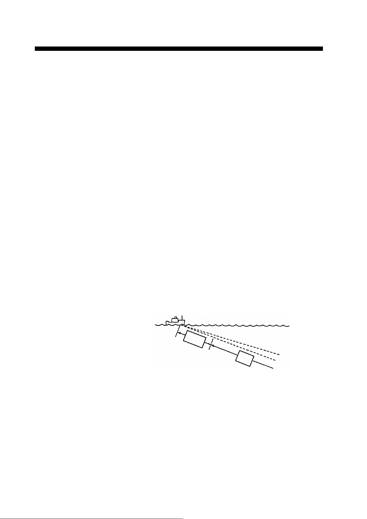
4. Suppressing Effects of Pitching and Rolling
Tilting in bow direction
Bearing mark at 0°
(bow direction);
beam stabilized
Echo not captured
by beam
Echo captured
by beam
The Motion Sensor MS-100 (option) compensates for the effects of
pitching and rolling to provide stable sonar pictures. You may enable
it as follows:
1. Press the [MENU] key to display the SCAN menu.
2. Use the RANGE control to select RANGE/BEARING.
3. Use the GAIN control to select STAB.
4. Press the [MENU] key to close the menu.
5. Operate the trackball to place the trackball mark on the bearing
you want to compensate by the MS-100.
6. Press the [R/B] key. A dashed line appears at the bearing selected
at step 5. The rolling and pitching of the ship in the direction of
the bearing mark is compensated, by automatically adjusting the
tilt angle.
Picture in direction
selected with bearing
mark is compesnated.
Note: The entire picture is not compensated in the full-circle scan-
ning; the tilt angle for each bearing cannot be changed. Only
one bearing is compensated and bearing error will result for
any bearing not stabilized.
Tilt can be controlled manually from 0° to 55°, however rolling and
pitching are compensated from -5° to 55° with the tilt angle at ±20°.
38
Page 45

5. Detecting Fish Echoes in Specific Area (Fish
Alarm)
The fish alarm alerts you to fish echoes in an area you select. Any
fish echoes entering the area will trigger the audio alarm. The fish
echo level which triggers the alarm may be selected from the scan
menu.
1. Press the [MENU] key to open the SCAN menu.
2. On the scan menu, use the RANGE control to select RANGE/
BEARING.
3. Use the GAIN control to select FISH/ALM.
4. Use the RANGE control to select FISH ALARM.
5. Use the GAIN control to select ON.
6. Press the [MENU] key to close the menu.
7. Use the trackball to place the trackball mark on the starting bearing and press the [R/B] key.
8. Use the trackball to place the trackball mark on the ending bearing and press the [R/B] key.
Alarm area
Starting point
Ending point
To disable the fish alarm, press the [R/B] key.
Note: The starting point may be selected at the outside or inside of
the alarm zone. You may also set a 360-degree alarm by setting the starting and ending points within three degr ees of each
other as in (c) and (d) in the figure below.
More than 3°
Within 3°
(a) (b) (c) (d)
39
Page 46

TRANSDUCER
6. Fish Alarm On/Off, Fish Alarm Sensitivity
The audio alarm for the fish alarm can be enabled/disabled and the
fish alarm sensitivity can be selected from the scan menu.
1. Press the [MENU] key to open the SCAN menu.
2. Use the RANGE control to select FISH ALARM.
3. Use the GAIN control to select the echo strength which will trigger the fish alarm. The setting range is 0 to 14. Choose "0" for no
audio alarm. For example, selecting "4" will trigger the audio
alarm when an echo whose strength is between 0 and 4 comes
into the fish alarm zone.
4. Press the [MENU] key to close the menu.
7. Menu Screen
Recalling
AUTO
TILT
MENUTX
Press the MENU key. The SCAN MENU or E/S
SECTOR
on the lower part of the screen. Note that the SCAN or E/S MENU
SCAN
can be recalled only when the transmitter is ON.
*--When the Echo sounder combination mode is selected.
*
MENU appears
RANGE
Changing Setting
-+-+
To change a setting, select item with the RANGE control and
setting with the GAIN control. The selected item is highlighted in
green and the selected setting is circumscribed in white. To scroll
GAIN
the menu, turn the RANGE control counterclockwise.
Note:
The gain and range of the sonar picture can not be changed
while the scan menu is displayed.
Exit from Menu Screen
To exit from the menu screen and return to the sonar screen, press
the MENU key.
Note:
Items shown in RED indicate they ar e locked to prevent alteration. To unlock a setting, call up the SYSTEM MENU.
40
Page 47

8. Menu Description
The CSH-5 MARK-2 employs three menu screens, MENU-1, MENU2 and SYSTEM Menu, to preset infrequently used functions. During
normal operation (transducer lowered, transmitter ON), the SCAN
Menu appears on the screen. This lets you adjust settings while observing the sonar picture.
noitacilppAesuotwoH
1-UNEM
2-UNEM
gnittesmetsysroF
UNEMMETSYS
.noitarugifnocmetsysruoy
.rettimsnartehtffogninrut
UNEMNACS
gnittesresuroF
UNEMS/E
.erutcip
9. Menu Screen Indications
MENU-1
** MENU-1 **
[MENU MODE] : MENU-1 MENU-2 SYSTEM
DISPLAY MODE : COMBI 1 NORM TEXT COMBI 2
HUE : 1 2 3 4
TX OUTPUT :8
PULSELENGTH : 7
TX CYCLE : 10
TVG NEAR : 6
TVG FAR : 7
AUTO SCN WDTH : ±10° ±20° ±40°±60°
AUTO TLT WDTH : ±2~10°±4~14° ±6~20° ±10~26°
HOR BEAM ANGL : WIDE NARROW
VER BEAM ANGL : WIDE NARROW
RES COL CURVE : LINEAR 1 2 3
COL EMPHASIS : 1 (LOW) 2 3 4 (HIGH)
FUNC KEY PROG : FUNC1 FUNC2 FACTORY
E/S RANGE : 240
E/S SHIFT : 0
E/S IR : ON OFF
E/S GAIN : 3.0
E/S CLUTTER : 2.0
E/S ADV ANCE : 1/1 1/2 1/4 1/8
E/S COL CURVE : LINEAR 1 2 3
E/S DRAFT : 0.0 (m)
( RANGE SW : U/D GAIN SW : L/R )
otgnidroccametihcaetceles,noitallatsniretfA
rorecudsnartehtgnisiarretfasmetitceleS
dnayekUNEMybneercsunemehtllaceR
ranosytilauqtsebehtrofmetiehttsujda
: indicates the items which may be locked.
: indecates the menu items available with the addition of
the CSH-5060 and external equipment.
41
Page 48

MENU-2
** MENU-2 ** ( RANGE SW : U/D GAIN SW : L/R )
[MENU MODE] : MENU-1 MENU-2 SYSTEM
EXT KP SYNC : OFF ON
RANGE MARKER : 1/4R 1/2R OFF
BEARING SCALE : ON OFF
CURRENT MARK : ON OFF
COURSE MARK : 10R 5R OFF
HEADING INDI : 32-AZI TRUE
CURRENT INDI : 32-AZI TRUE ±180° 360°
EVENT INDI : 32-AZI TRUE ±180° 360°
MARK INDI : ±180° 360°
POSITION DATA : L/L TD
SYSTEM MENU
** SYSTEM MENU ** ( RANGE SW : U/D GAIN SW : L/R )
[MENU MODE] : MENU-1 MENU-2 SYSTEM
HEADING ADJ : 0°
AUTO SCN SPD : LOW HIGH
AUTO TLT SPD : LOW HIGH
UNIT : METERS FEET FATHOMS PA/BRA
SHIP’S SPD/BR : LOG/GY CI NAV
LOG PULSE : 200 400
CI BAUD RATE : 4800 2400 1200
NAV FORMAT : CIF NMEA183 NMEA182
NAV BAUD RATE : 4800 2400 1200
NAV DATA : GPS LC DEC DR
LA ALL
COMBI SCALE : RIGHT LEFT
MENU SELECT : LOCK UNLOCK
SUB TEXT INDI : OFF ON
LANGUAGE : ENGLISH (JAPANESE) ESPANOL DANSK
SELF TEST : SINGLE P ANEL COLOR GRAY
CONTI SIO ECHO-1 ECHO-2
~
42
Page 49

SCAN MENU
** SCAN MENU ** ( RANGE SW : U/D GAIN SW : L/R )
** SCAN MENU ** ( RANGE SW : U/D GAIN SW : L/R )
MENU MODE : SCAN E/S
MENU MODE : SCAN E/S
DISPLAY MODE : COMBI-1 NORM TEXT COMBI-2
HUE : 1 2 3 4
TX OUTPUT :8
PULSELENGTH : 7
TX CYCLE : 10
TVG NEAR : 6
TVG FAR : 7
DELETE COLOR : 0
AUTO SCN WDTH : ±10° ±20° ±40°±60°
AUTO TLT WDTH : ±2~10°±4~14° ±6~20° ±10~26°
MARK ERASE : COURSE SHIP EVENT
RANGE/BEARING : NORMAL TARGET STAB. FISH/ALM
FISH ALARM : ON OFFF
ALARM LEVEL : 9
HOR BEAM ANGL : WIDE NARROW
VER BEAM ANGL : WIDE NARROW
RES COL CURVE : LINEAR 1 23
COL EMPHASIS : 1 (LOW) 2 3 4 (HIGH)
FUNC KEY PROG : FUNC1 FUNC2 FACTORY
E/S MENU
** E/S MENU ** ( RANGE SW : U/D GAIN SW : L/R )
MENU MODE : SCAN E/S
HUE : 1 23 4
E/S RANGE : 320
E/S SHIFT : 0
E/S IR : ON OFF
E/S GAIN : 3.0
E/S CLUTTER : 1.0
E/S ADV ANCE : 1/1 1/2 1/4 1/8
E/S COL CURVE : LINEAR 1 2 3
E/S DRAFT : 0.0(m)
43
Page 50

10. Contents of Menu Items
This section describes the menu items available with the addition of
the CSH-5060 and external equipment.
MENU-1 (SCAN, E/S Menu)
Scan menu
Item
MENU MODE
DISPLAY
MODE
DELETE
COLOR
Contents
Selects a menu; MENU-1, MENU-2 or SYSTEM Menu.
Selects a picture display mode among the four below.
9/10
1/10
NORM TEXT COMBI 1 COMBI 2
3/5
2/5
3/5
2/5
NORM: Normal Mode; displays a sonar picture on entire screen.
TEXT: Normal + Text; The text area appears on the lower area. This area
is for displaying own ship’s position, ship’s speed, course, depth
and tidal current.
COMBI 1: Sonar Combination (Normal + Signal on Bearing Mark); The
echoes on the bearing mark direction appears on the lower 2/5ths
of the screen.
COMBI 2: Echo Sounder Combination (Normal + Echo Sounder); When an
external echo sounder is connected, the picture from the echo
sounder appears on the lower 2/5ths of the screen.
Deletes echo colors whose strength is lower than the strength selected here.
Useful for eliminating noise.
MARK ERASE
(for scan menu
only)
RANGE/
BEARING
(for scan menu
only)
Selects the item to erase with the [TX] key; COURSE (track), SHIP (own
ship mark), EVENT (event mark). Each pressing of the key deletes eldest
track, ship or event mark.
This menu chooses the function of the [R/B] key.
NORM - The echoes in the direction designated by the bearing
mark are stabilized against the ship’s pitching and rolling.
TARGET - Echo designated by the target lock mark is automatically tracked.
STAB, - Compensates for the effects of pitching and rolling. Requires
Motion Sensor MS-100
FISH/ALM Enables the user to set the fish alarm zone.
FISH ALARM Disables/enables the audio alarm for the fish alarm.
ALARM LEVEL Chooses echo level which will trigger the fish alarm.
44
Page 51

E/S Menu
Item
E/S SHIFT
E/S IR
E/S GAIN
E/S CLUTTER
E/S ADVANCE
E/S COL CURVE
(Response Color
Curve)
Contents
Shifts the start depth of the display range and the maximum value is about
1000 m irrespective of the depth unit. The unit shift value is determined by
the range in use. See table below.
M FT FA P/B
1
220501010
3 40 100 20 20
4 50 100 25 25
5 50 200 40 40
6 100 200 50 50
7 100 300 50 50
Turns the Interference Rejector on and off.
Controls the gain of the Echo Sounder picture.
Eliminates the noise appearing on the screen.
Adjusts the picture advancement speed. 1/1 is fastest, 1/8 is slowest.
This menu sets the balance between weak and strong echoes. In the LINEAR
position, output (echo strength displayed) varies proportionally with input
(actual echo strength). Select a higher setting to emphasize weak echoes.
Weak echoes are displayed in stronger echo colors as the number goes higher.
The standard setting is the LINEAR position.
10
25 5
5
E/S DRAFT
Adjusts the draft of the own ship according to loading conditions.
Irrespective of the depth unit selection, the draft adjustment is available from
0 to 10 m in 0.5 m steps.
Selects the display range of the Echo Sounder from the table below.E/S RANGE
M FT FA P/B
110
2
3
4
5
6
7
Depth unit may be selected on the SYSTEM Menu.
20
40 120 20
80 240 40
120 360 60
160 480 80
240 720 120
320 960 160
60 10
20
40
60
80
120
160
45
Page 52

MENU-2 (Refer to pages 47 to 51 for location on the screen.)
metIstnetnoC
ELACSGNIRAEB.ffodnanoelacsgniraebcinortceleehtsnrutunemsihT
KRAMTNERRUC.ffodnanokramtnerrucehtsnrutunemsihT
KRAMESRUOC :R(R5roR01morftolpenilesruocehtfohtgnelehtstcelesunemsihT
.tiesare
IDNIGNIDAEH.noitacidnigniraebeurtrohtumiza-23stceleS
IDNITNERRUC rogniraebeurt,htumiza-23;dohtemnoitacidniatadtnerrucehtstceleS
(gniraebevitaler ± )dohtemnoitacidni˚063ro˚081
DNITNEVE -23;kramneveehtfodohtemnoitacidniatadgniraebehtstceleS
)dohtem
IDNIKRAM gniraebdnallabkcartehtfodohtemnoitacidniatadgniraebehtstceleS
.skram
ATADNOITISOP .DTroL/L,dohtemyalpsidnoitisops'pihsnwoehtstceleS
ot"FFO"tceles,yrassecentonsiyalpsidenilesruocfI.)esuniegnar
(gniraebevitalerrogniraebeurt,htumiza ± noitacidni˚063ro˚081
SYSTEM MENU
metIstnetnoC
RB/DPS'PIHS .atadenilesruocsdeefhcihwecruosehtstcelesunemsihT
ESLUPGOL snoitcelesehT.detcennocgoldeepsehtfosnoitacificepsehtotrefeR
TAMROFVAN.noitacinummocatadroftamrofehtstceleS
ATADVAN atadnoitisopsdeefhcihwtnempiuqenoitagivanehtstcelesunemsihT
ELACSIBMOC yalpsidnoitanibmocehtnielacsehtfonoitacolehtstcelesunemsihT
.elim/seslup004ro002eraelbaliava
ETARDUABIC ]IC[ehtotdetcennoctnempiuqeehtfosnoitacificepsehtotrefeR
.spb0084signittesdradnatsehT.)rotacidnitnerruc(rotcennoc
ETARDUABVAN ehtotdetcennoctnempiuqenoitagivanehtfosnoitacificepsehtotrefeR
.spb0084signittesdradnatsehT.).cte,SPG,narol(rotcennoc]VAN[
tsehgihehthtiwatadnoitisopeht,detcelessi"LLA"fI.8-HSCehtot
tsehgihehtsahSPG;elbaliavaatadlarulpmorfnesohcsiytiroirp
.tsewoleht,ALehtdnaytiroirp
.edom
46
Page 53

Indications
2
1. Normal Mode (NORM)
4
1
5
1
Electronic Bearing Scale
2
Mark Indication (Bearing)
4
Heading Indication
5
Current Mark
6
3
6
3
Course Mark
6
Own Ship’s Mark
47
Page 54

2. Normal + Text Mode
!0
!1
9
7
Current Indication
8
Position Data
9
Latest Event Mark Data
!0
Past Event Mark
!1
Navigational Data
8
7
48
Page 55

3. Echo Sounder Combination Mode (COMBI 1)
Normal + Echo Sounder
Sonar
Picture
16 Color Bar
Echo
Sounder
Picture
49
Page 56

4. Sonar Combination (COMBI 2)
Normal + Signal on R/B Mark
Sonar
Picture
16 Color Bar
Signal on
R/B Mark
50
Page 57

Marks and Data
This section explains the Marks and Data available from the equipment interfaced. Pages 24 to 25 show the location of these Marks and
Data.
New Marks and Data
Latest Event Mark
Data
)(
B
°
Own Ship’s Mark
Elecrtonic Bearing
Scale
N
WE
S
Course Line Mark
Current Mark
3
2
1
Description
The position data of the latest event mark, i.e., horizontal range (→),
present depth (↓) and bearing. ( ) shows the latest event mark
original depth which remains unchanged even if ship moves or tilt angle
is changed. When the event mark is erased on the MENU screen, the
above data disappear from the screen.
You can plot up to 10 own ship’s marks on the course line. The mark can
be erased on the MENU screen.
The electronic bearing scale is available with gyrocompass connection. It
rotates with own ship’s movement.
The own ship’s course line is plotted by a solid line when gyrocompass /
speed log or a navigation device (GPS or Loran C) is connected.
The course line length is selectable from 5 or 10 times the range in use.
You can erase the line by the MENU screen.
When a current indicator is connected, the current mark shows the speed
and direction of three current layers, numbered 1 through 3. The current
speed is indicated by the length of the vector. However, no vectors are
developed if the current speed is 0.1 knots or less. The vector shows
current direction. The current mark can be erased on the MENU screen.
Tridal Current Data
C1: .
C2: .
C3: .
Navigational Data
S: .
C:
D:
T: .
Own Ship’s Position
Data
° .N
° .E
North Mark
Target Lock Mark
In the Normal Mode (with Text), current speed and direction for three
current layers appear in the text area. The display method for the current
direction can be selected on the MENU screen.
Own ship’s speed(S), heading(C), water depth(D) and water
temperature(T) can be displayed on the text area when appropriate
equipment are interfaced.
Own ship’s position is shown in the Normal (with Text) mode (Position
fixing equipment is required.)
The north mark is available with gyrocompass connection.
In the target lock mode (automatic echo tracking), the target lock mark
appears when the [R/B] key is depressed. To erase the mark, press the
[R/B] key again.
51
Page 58

Event Mark Position Output
Connected to a navigator, the CSH-5 MARK-2 can output event mark
position data to external equipment when the [EVENT] key is operated. The data sentence output is "SSTLL" (NMEA, IEC-1162 format).
52
Page 59

General
WARNING
CAUTION
WARNING
12. MAINTENANCE
The CSH-5 MARK-2 is designed and constructed to provide many
years of trouble-free performance when properly maintained. Userperformable maintenance and important points to be observed are
outlined in the figure below.
Do not open the cover of
the equipment.
This equipment uses high
voltage electricity which can
shock, burn, or cause death.
Only qualified personnel
should work inside the
equipment.
Keep screen and filter clean!
Put on cover after operation.
Do not use thinner or benzine for
cleaning. Use a water-moistened soft
cloth.
Keep magnets and cassette tapes away!
Handle with care!
Corrosion may occur!
Keep heater away! Allow
room for ventilation.
Display Unit
Apply MOLYTONE grease #2 every
six months.
Color may become distorted!
CAUTION
The zinc block attached near the
transducer must be replaced at
periodic maintenance.
The junction between the
transducer and main shaft may
corrode, which can result in loss of
the transducer or water leakage
inside the ship.
Raise transducer and apply
DAPHAECOROAEX #2
over the main shaft every six months.
Reapply one coat of antifaulant
"MARINE STAR 20 Mod (Red-N)"
(no other paints are allowed) on the
washed polyuretane transducer face
upon dry-docking at least once a
year, to prevent seashells and
seaweeds from growing
Hull Unit
53
Page 60

13. UNIT DIAGNOSTIC TESTS
This unit has eight built-in diagnostic tests which check it for proper
performance. Although the tests are designed primarily for use by the
service technician, they can also be executed by the user to identify
defective components. However, never attempt to check inside the
unit; there are no user-serviceable parts inside. Any repair work is
best left to a qualified technician.
Turning-on/off Diagnostic Test
1. Press the MENU key, and then select the system menu by operating the GAIN control.
2. Select the “SELF-TEST’ function by operating the RANGE switch.
Select an appropriate self-test by operating the GAIN control.
SUB
LANGUAGE ENGLISH JAPANESE ESPANOL DAN SK
SELF TEST SINGLE PANEL COLOR GRAY
CONTI SIO ECHO-1 ECHO-2
3. Press the TX switch to execute the self-test.
4. To exit from the self-test screen, press the MENU key for a few
seconds. When the “SINGLE” is selected, the unit automatically
restores the system menu after the test is completed.
Description of Unit-diagnostic Tests
Single Test
This test checks the Main Board and T ransceiver Unit for proper operation one time, after which normal operation is restored. After the
test is completed, the results are indicated as OK (normal operation)
or NG (malfunction), to the right of the device checked.
SINGLE TEST
~
∗∗∗∗: 0635 e 107kHz
0644 e 85kHz
MAIN 105-0541-XXX 105-0542-XXX
ROM = OK
RAM = OK
P.W = OK
TRX 105-∗∗∗∗-XXX 105-∗∗∗∗-XXX
ROM = OK
RAM = OK
I/F 105-0267-XXX
ROM = OK
RAM = OK
XXX : Version number
54
Display Unit Program No. is displayed
and ROM, RAM and P.W (Password)
are checked for proper operation.
TRX (Transceiver) Unit Program No.
is displayed, and ROM and RAM are
checked for proper operation.
ROM and RAM of the interface
module CSH-5060 (option) are
checked for proper operation. If the
interface module is not provided,
program number and check result are
not displayed.
Page 61

Conti Test
This is a continuous test of the Display and Transceiver Units. Additionally checked devices are DROM and DRAM.
CONTI TEST
MAIN 105-0541-XXX 105-0542-XXX
ROM = OK
RAM = OK
P.W = OK
DROM = OK
DRAM = OK
DPRAM = OK
TRX 105-∗∗∗∗-XXX 105-∗∗∗∗-XXX
ROM = OK
RAM = OK
DROM = OK
I/F 105-0267-XXX
ROM = OK
RAM = OK
DPRAM = OK
GYRO = OK
LOG = OK
PRESS [MENU] 2 or 3 SECONDS TO STOP SELFCHECK
∗∗∗∗: 0635 e 107kHz
0644 e 85kHz
Not displayed if interface module
CSH-5060 is not provided.
Panel Test
This test checks the controls on the front panel and the control box
for proper operation.
PANEL TEST
00
00
••
••
000000
00 X=00
7 300 Y=0
00
PRESS [MENU] 2 or 3 SECONDS TO STOP SELFCHECK
Main Panel
Press each control one by one.
The figure should change if the
control is functioning properly.
Control Box
Repeat the above procedure.
SIO Test
This test checks the input/output parts of the Transceiver Unit. The
results of the test are indicated as OK or NG.
SIO TEST
MAIN SIO1 = OK
SIO2 = OK
I/F SIO-NAV= NG
SIO-CI = NG
SIO1: Checks communication line
between display and
transceiver unit.
SIO2, SIO-NAV and SIO-CI check
communication line between interface
module (option) and display unit.
Short-plug is required to conduct this
test.
PRESS [MENU] 2 or 3 SECONDS TO STOP SELFCHECK
55
Page 62

Color T est
The color test checks for proper display of all colors.
COLOR TEST
16 Color display
WHT RED GRN
PRESS [MENU] 2 or 3 SECONDS TO STOP SELFCHECK
Echo-1 Test
The echo-1 test checks echo processing circuits in the display unit for
proper operation.
DISPLAY ECHO TEST
→
240
→
236
↓
41
B
281°
R29 B358°
PRESS [MENU] 2 or 3 SECONDS TO STOP SELFCHECK
R400
T10°
G3.0
56
Page 63

Gray Test
The gray test checks for proper display of monochrome characters
and markers. Concentric rings and a monochrome test bar are displayed.
GRAY TEST
............
PRESS [MENU] 2 or 3 SECONDS TO STOP SELFCHECK
Echo-2 Test
The echo-2 test checks echo processing circuits in the transceiver
and display units.
PRESS [MENU] 2 or 3 SECONDS TO STOP SELFCHECK
Set the VP control on the main
panel to "OFF" position.
Radial pattern as above is
displayed.
57
Page 64

14. CHARACTERISTICS OF THE ULTRASONIC WAVE IN W ATER
The purpose of this chapter is to provide an overview of the characteristics of the ultrasonic wave in water.
Sound Velocity
It is generally known that an ultrasonic wave travels 1500 meters per
second in sea water, but in practice, some amount of variation arises
depending on the season and area from differences in the following
three factors:
Water temperature .............................. θ [ C]
Salinity density ...................................S [%]
Water pressure (water depth)..............h [m]
°C
0
1
2
3
4
5
6
7
8
9
10
11
12
13
14
15
16
17
18
19
20
Therefore, for propagation in surface water the velocity changes not
only by area but also by direction of the wave propagation. The equation obtained thru numerous measurements is;
C= 1410 + 4.21θ - 0.037θ
Velocity (m/sec)
1445.4
1450.0
1454.4
1458.8
1463.1
1467.2
1471.3
1475.3
1479.2
1483.0
1486.7
1490.3
1493.8
1497.3
1500.6
1503.8
1507.0
1510.0
1513.0
1515.9
1518.7
2
+ 1.145S + 0.0168h [m/s]
Correction value with respect to
Depth and Temperature (m/s.)
Depth
(m)
°C
100 200 300 400 500 600 700
5
1.8 3.6 5.4 7.3 9.1 10.9 14.5
10
1.8 3.6 5.4 7.2 9.0 10.8 14.5
15
1.8 3.6 5.4 7.2 9.0 10.8 14.4
20
1.8 3.6 5.4 7.2 9.0 10.8 14.4
25
1.8 3.6 5.4 7.3 9.1 10.9 14.5
Fig.1 Sound Velocity
58
Page 65

Research in the waters throughout the world has revealed that there is
a difference of approximately 100 m/s between the areas where the
velocity is maximum and minimum
Generally, the velocity increases as follows, provided that salinity
density is constant:
• 3 m/s for every 1 degree rise of water temperature
• 1.7 m/s for every 100 m increase of water depth
Absorption and Attenuation
An ultrasonic wave emitted into water becomes weaker in intensity
as it goes away from the emitting source. Principle causes of attenuation are:
1. Acoustic energy of the ultrasonic wave decreases gradually through
reflection, refraction and diffusion in water.
2. Acoustic energy is absorbed by the viscosity of the medium (water) and converted into other forms of energy.
10000
1000
100
10
1
0.1
0.01
Absorption (db/km)
0.001
0.0001
10210310410510610
Frequency (Hz)
5°c
The higher the frequency, the greater the absorption and attenuation
of the ultrasonic wave as shown below. In other words, the absorption coefficient is a function of the frequency . Generally , total ener gy
loss encountered on the way to and from a target is expressed
TL [dB] = 40 logR + 2αR
where R ----- Range to a target
α ----- Absorption coefficient
160
150
140
130
f=200kHz
120
α=64.5db/km
110
100
TL (db)
90
80
7
70
60
50 100 1000 10000
570m 2400m
f=200kHz
α=33db/km
Range (m)
59
Page 66

Refraction
An ultrasonic wave transmitted in water does not travel straight but is
more or less refracted. This refraction is caused by the variation of
propagation velocity in water. If the velocity decreases (temperature
decreases) with depth, the top part of the wave front moves faster
than its bottom part, and gradually the front bends downwards. In the
same way, it bends upwards if the sound velocity increases (temperature rises) with depth.
In other words, the ultrasonic wave refracts toward colder water.
0
50
Water Depth
100
(m)
0.5 1 1.5 2
Distance (Km)
Here, a fishing ground off Hokkaido island in Japan is taken as an
example.
A
Within 100m
Propagation path
18°
16°
12°
Big Fish
School
Water Temp.
0
50
Water Depth
100
(m)
small fish
B
school
0.5 1 1.5 2
Distance (Km)
Seaface
Large difference in
density
18°
20°
Water Temp.
18°
Fishing Ground off Hokkaido (Summer)
In summer, there is a large difference in salinity density below and
above the 100 m deep point. An ultrasonic wave emitted almost in
the horizontal direction propagates within 100 m deep water in the
same way as a radio wave in a waveguide. As a result, even a small
fish school is sometimes detected at an unexpected long range or on
the contrary, detection of a large fish school does not extend to a
relatively long range. These phenomena are encountered when two
fish schools lie in positions “A” and “B” of the illustration.
60
Page 67

The drawing below shows how temperature variation affects sound
propagation with respect to different emitting directions (tilt angles).
Beams tilted five and ten degrees bend upward at 400 m and 600 m
points respectively. Beams tilted down more than 15 degrees travel
in almost straight lines. Between the two beams, a blind zone is created beyond the 600 m point. In this zone nothing can be detected.
The shown drawing is only an example calculated by a computer,
based on the temperature with depth as shown in the left column of
the figure. In actual fishing grounds, the temperature distribution and
subsequently the behavior of the sound beam is much more complicated. It is, therefore, for effective use of sonar, necessary to know at
least roughly how the temperature is distributed in various waters.
010200
0
0
50
100
150
Sea depth (m)
200 400 600 800 1000
-10
Blind zone
-15
-20
-25
-30
-35
Adverse Effect of Air Bubbles
1200 1400 1600
0 (DEG)
-5
1800
2000
Even infinitesimal air bubbles in sea water (liquid medium) affect
propagation of ultrasonic sound. This is because the cubic elasticity
of gas is extremely small when compared with that of liquid; the air
bubbles violently vibrate (contract and expand) by the action of sound
pressure, diffusing the ultrasonic wave and dispersing part of the
acoustic energy. In a liquid which contains a large amount of air
bubbles, attenuation of an ultrasonic wave increases and the wave is
reflected at the boundary of waters which contain and do not contain
air bubbles.
From the above it can be said that reflection occurs in the boundary
where the density (P) of the material (medium) that is, the velocity of
the ultrasonic wave changes. The velocity of an ultrasonic wave with
respect to its medium is 200 thru 400 m/s in gas, except for hydrogen
and helium; 900 thru 2000 m/s in liquid (several times higher than in
air) and 2000 thru 6400 m/s in ordinary metal.
61
Page 68

The product of the density (P) and the velocity (C) is called intrinsic
acoustic impedance and in the boundary between two media which
has extremely different C from each other , most of the acoustic power
is reflected and only a small portion penetrates. (In the boundary between water and air, the acoustic energy penetrates with a loss of
approximately 30 dB, that is approximately 0.1 % of the energy penetrates from one medium to the other.)
Reflection from water which contains air bubbles is caused by the
fact that the cubic elasticity decreases in aerated water, causing the
intrinsic acoustic impedance to change.
In the actual sonar operation, adverse effect of air bubbles is shown
by interrupted display of target echoes which occurs while crossing
over the wake of another boat or when the sonar transducer passes
above the air bubbles generated by own ship.
Air bubbles in water have a resonant frequency of l5 kHz thru 100
kHz and hence the ultrasonic wave in this frequency range is most
strongly affected.
Reflection at Seabed and Fish School
The nature of the seabed is roughly classified into the following four
kinds: crag, sand, mud and seaweeds. In addition, shells and carcass
of animals (especially coral) imbedded in the seabed cause reflection
loss.
Reflection Loss Lb = 20 log
The actual reflection loss in the sea is shown below. The reflection
loss remains almost constant up to 50 kHz and then gradually increases.
Mud
Sand
Refelction Loss (dB)
Rock
Frequency (kHz)
Incident sound pressure
Reflection sound pressure
(db)
The relation of frequency vs reflection loss for mackerel is shown
below. The calculated value and actually measured value nearly coincide. And also, on the contrary to the seabed reflection, the reflection loss decreases as the frequency increases. The “K” in the figure
is the coefficient of fish shape, where its larger value introduces smaller
reflection loss.
62
Page 69

Reflection Loss (dB)
Reflection Loss (dB)
Frequency (kHz)
Reflection Loss
(Mackerel No.1)
Species
Sardine
Bonito
Horse Mackerel
Sea Bream
Turbot
Average
Frequency (kHz)
Reflection Loss
(Mackerel No.2)
Incident Direction of Ultrasonic Wave
Back Side Head
1 2 0.13
120.5
0.8-1.2 1.4-2.2 0.4-0.6
0.9 3 0.45
2
120.4
63
Page 70

SPECIFICATIONS
1. Display
PPI display on 14" non-glare, high resolution color CRT
2. Display Color
16 colors according to echo strength
3. Numeric information
Scanning Data (Range, Tilt angle, Gain)
Trackball Mark Data (Slant range, Horizontal range,
Depth, Bearing)
Range/Bearing Mark Data (Range, Bearing)
4. Range/Pulselength
Range
Basic Range(m)
85
100
150
200
250
300
350
400
450
500
600
800
1000
1200
1600
NOTE:
1. Ranges shown for off-center “on” are maximum.
2. Under certain circumstances, a target (fish school) may
not be detected due to its nature or because of sea
conditions, even if it is located within the display range.
Maximum Display Range (m)
OFF-Center "OFF" OFF-Center "ON"
110
130
195
260
325
390
455
520
585
650
780
1040
1300
1560
2080
135
160
240
320
400
480
560
640
720
800
960
1280
1600
1920
2560
Pulselength 0.5ms to 20ms, interlocked with range
PRR 0.2 sec to 4.0 sec interlocked with range. (can
be changed in 11 steps.)
SP-1
Page 71

5. AUDIO SEARCH
Searching Method Echoes in the direction of the bearing mark are
audibly monitored by the built-in loudspeaker.
Audio Sector 20˚, 40˚, 80˚, 120˚ (selectable)
Audio Output 2W
Audio Frequency 800Hz
6. Transmitter/Receiver
Transmitter High power MOS FET amplifier with 11-step
power reduction switch
Receiver Low noise superheterodyne, continuously scan-
ning beam forming
Tx Frequency 55kHz or 68kHz
7. Tilt Angle
Tilt Angle 0˚ to 55˚
Auto Tilt ±2˚ to ±26˚ selectable
8. Hull Unit
400mm travel 600mm travel
Transducer T ravel
Raising Time
Lowering/Time
Driving System
Allowable Ship’s Speed
Remote electric control
18 knots max. (16 knots during raise/lower
operation)
400m 600m
14 sec. 20 sec.
14 sec. 20 sec.
9. Other Features
Interference Rejector, Video Processing, Noise Limiter, Automatic
Tilt Scanning Overvoltage Warning, Unretracted Transducer Warning
10. Power Supply, Power Consumption
100/115/200/240VAC, 50/60Hz, 1φ, 0.4kVA on average, 1kVA max.
24/32VDC with optional DC-AC inverter CSH-5050.
SP-2
Page 72

INDEX
A
Absorption 59
AGC control 17
Air bubbles 61
Attenuation 59
AUDIO control 21
AUTO TILT key 6
C
Color test 56
Conti test 55
Control box panel 5
D
Data description 25
DEMAG button 3
Diagnostics
color test 56
conti test 55
echo-1 test 56
echo-2 test 57
gray test 57
panel test 55
single test 54
SIO test 55
turning on/off 54
E
Echo-1 test 56
Echo-2 test 57
EVENT DELETE key 6
EVENT key 6
F
event mark 36
indications 47-50
marks and data 51
menu description 41-43
menu screen 40
MENU-1 41
MENU-2 42
numeric information 35
operation 36–46
own ship mark 36
SCAN menu 43
specifications 35
SYSTEM menu 42
target lock mark 36
IR control 19
M
Main panel 4
Maintenance
zinc block replacement 53
Mark description 24
MENU key 5
Menu operation
basic 7
scan menu operation 32
system menu description 33
N
NOISE LIM control 18
O
OFF-CENTER key 6, 22
Output power 18
Overvoltage remedy 30
F1, F2 keys 22
False echoes (sidelobe) 29
Fish school echo 27
G
GAIN control 5, 15
Gray test 53
I
Interface Module CSH-5060 35–51
available menu items 44-46
display marks 35
display mode 35
E/S menu 43
P
Panel test 55
POWER switch 30
Powering off 11
Powering on 10
Pulselength 17
R
R/B key 6, 21
Range and bearing measurement 20
RANGE control 5
RANGE switch 11
Refraction 60
Index-1
Page 73

S
Scan menu 8
Sea surface reflections 28
Seabed echo 26
SECTOR SCAN key 6, 21
Sidelobe 29
Single test 54
SIO test 51
Sound velocity 58
System configuration 2
System menu 33
T
Tilt angle
and discriminating fish echoes from bottom 12
for surface fish 13
general selection 11
TILT lever 5, 11
Trackball 5
TRANSDUCER switch 5, 11, 30
TVG adjustment 16
TX cycle 19
W
Wake recognition 28
Index-2
 Loading...