

Page 1
COLOR SCANNING SONAR
CSH-5L/CSH-8L
Page 2

9-52 Ashihara-cho,9-52 Ashihara-cho,
A
A
*
00080940402
**00080940402
*
*
00080940402
**00080940402
*
*
OME
13190
C
00
**OME
13190
C
00
**OME
13190
C
00
**OME
13190
C
00
*
Nishinomiya, JapanNishinomiya, Japan
Telephone :Telephone : 0798-65-21110798-65-2111
faxfax 0798-65-42000798-65-4200
ll rights reserved.
ll rights reserved.
::
PUB.No.PUB.No. OME-13190OME-13190
Printed in JapanPrinted in Japan
Your Local Agent/DealerYour Local Agent/Dealer
IRST EDITION :
IRST EDITION : DECDEC .. 20022002
CC :: JULJUL .. 06, 200406, 2004
(( YOSHYOSH ))
CSH-5L/8LCSH-5L/8L
* 0 0 0 8 0 9 4 0 4 0 2 ** 0 0 0 8 0 9 4 0 4 0 2 *
* O M E 1 3 1 9 0 C 0 0 ** O M E 1 3 1 9 0 C 0 0 *
Page 3
SAFETY INSTRUCTIONS
WARNING
ELECTRICAL SHOCK HAZARD
Do not open the equipment.
Only qualified personnel
should work inside the
equipment.
Immediately turn off the power at the
switchboard if water leaks into the
equipment or something is dropped in
the equipment.
Continued use of the equipment can cause
fire or electrical shock. Contact a FURUNO
agent for service.
Do not disassemble or modify the
equipment.
Fire, electrical shock or serious injury can
result.
WARNING
Use the proper fuse.
Fuse rating is shown on the equipment.
Use of a wrong fuse can damage the
equipment.
Do not operate the equipment with wet
hands.
Electrical shock can result.
Do not place liquid-filled containers on
the top of the equipment.
Fire or electrical shock can result if a liquid
spills into the equipment.
Immediately turn off the power at the
switchboard if the equipment is emitting
smoke or fire.
Continued use of the equipment can cause
fire or electrical shock. Contact a FURUNO
agent for service.
Make sure no rain or water splash leaks
into the equipment.
Fire or electrical shock can result if water
leaks in the equipment.
i
Page 4
CAUTION
Do not exceed 18 knots with the transducer lowered and do not exceed 16
knots when lowering or raising the
transducer.
The transducer may become damaged.
Turn off the hull unit before using the
hand crank.
Bodily injury may result if the power is not
turned off.
The zinc block attached near the
transducer must be replaced yearly.
The junction between the transducer and
main shaft may corrode, which can result
in loss of the transducer or water leakage
iinside the ship.
WARNING LABEL
A warning label is attached to all units
of the system. Do not remove any label.
If a label is missing or damaged, contact
a FURUNO agent or dealer about
replacement.
WARNING
To avoid electrical shock, do not
remove cover. No user-serviceable
parts inside.
Name: Warning Label (1)
Type: 86-003-1011-1
Code No.: 100-236-231
ii
Page 5

TABLE OF CONTENTS
FOREWORD.............................................................................................................vi
SYSTEM CONFIGURATION....................................................................................vii
1. OPERATIONAL OVERVIEW .............................................................................1-1
1.1 Control Unit................................................................................................................1-1
1.2 Remote Controller (option) .........................................................................................1-2
1.3 Basic Operating Procedure........................................................................................1-3
1.3.1 Turning on the power .......................................................................................1-3
1.3.2 Lowering the transducer...................................................................................1-3
1.3.3 Transmitting .....................................................................................................1-4
1.3.4 Adjusting backlighting of control unit ................................................................1-5
1.3.5 Choosing a display mode.................................................................................1-6
1.3.6 Choosing the display range..............................................................................1-8
1.3.7 Adjusting the gain ............................................................................................1-9
1.3.8 Retracting the transducer, turning off the power ...............................................1-9
1.4 Setting the Tilt Angle ................................................................................................1-10
1.4.1 Automatic tilt on/off.........................................................................................1-10
1.4.2 Bottom and tilt angle ......................................................................................1-12
1.4.3 How to discriminate fish echoes from the bottom ...........................................1-12
1.4.4 Points to consider...........................................................................................1-13
1.4.5 Tilt angle for surface fish ................................................................................1-13
1.4.6 Suitable tilt angle............................................................................................1-14
1.5 Finding Range and Bearing to a Target ....................................................................1-14
1.6 Sonar Menu Overview..............................................................................................1-15
1.6.1 Operating procedure ......................................................................................1-15
1.6.3 Sonar menu description ................................................................................. 1-16
2. FINE TUNING THE SONAR PICTURE
2.1 Eliminating Unwanted Echoes....................................................................................2-1
2.2 Displaying Surface Fish Clearly .................................................................................2-2
2.3 Suppressing Bottom Tail ............................................................................................2-2
2.3.1 AGC.................................................................................................................2-2
2.3.2 Pulse length .....................................................................................................2-3
2.3.3 2ND AGC.........................................................................................................2-3
2.4 Suppressing Bottom and Sea Surface Reflections in Shallow Fishing Grounds .........2-4
2.5 Rejecting Sonar Interference and Noise.....................................................................2-5
2.5.1 Identifying noise source ...................................................................................2-5
2.5.2 Rejecting noise with the interference rejector...................................................2-5
2.5.3 Rejecting noise with the noise limiter ...............................................................2-5
2.5.4 Rejecting interference with TX cycle ................................................................2-6
2.6 Choosing Beamwidth .................................................................................................2-7
2.6.1 Horizontal beamwidth.......................................................................................2-7
2.6.2 Vertical beamwidth ...........................................................................................2-7
2.7 Deleting Weak Echoes...............................................................................................2-7
2.8 Echo Averaging..........................................................................................................2-7
....................................................................2-1
iii
Page 6

3. ADVANCED SONAR OPERATION ...................................................................3-1
3.1 Tracking a Fish School (target lock)........................................................................... 3-1
3.2 Detecting Fish Schools Aurally .................................................................................. 3-3
3.3 The Fish Alarm .......................................................................................................... 3-4
3.4 Measuring Fish School Speed ................................................................................... 3-5
3.4.1 Entering a fish mark......................................................................................... 3-5
3.4.2 Deleting individual fish marks .......................................................................... 3-6
3.5 Relocating Fish School for Easy Observation ............................................................ 3-6
3.6 Event Mark, Own Ship Position Mark......................................................................... 3-7
3.6.1 Event mark ...................................................................................................... 3-7
3.6.2 Entering an own ship position mark ................................................................. 3-8
3.6.3 Deleting an event mark.................................................................................... 3-8
3.7 Collectively Deleting Marks........................................................................................ 3-9
3.8 Function Keys (F1-F4)............................................................................................. 3-10
3.8.1 Operating the function keys ........................................................................... 3-10
3.8.2 Programming for fishing ground or target fish ................................................ 3-10
3.8.3 Programming specific function....................................................................... 3-11
3.8.4 Confirming function key program ................................................................... 3-12
3.9 Suppressing Effects of Pitching and Rolling (Stabilizer) ........................................... 3-13
4. ECHOSOUNDER MODE ...................................................................................4-1
4.1 Choosing the Range.................................................................................................. 4-1
4.2 Adjusting the Gain ..................................................................................................... 4-2
4.3 Picture Advance Speed.............................................................................................. 4-3
4.4 Measuring Depth ....................................................................................................... 4-3
4.5 Suppressing Interference........................................................................................... 4-4
4.6 Suppressing Low Level Noise.................................................................................... 4-4
4.7 Erasing Weak Echoes ............................................................................................... 4-5
4.8 Other Items on the Sounder Menu............................................................................. 4-6
5. MARKS AND DATA...........................................................................................5-1
5.1 Marks and Data on the Normal Display...................................................................... 5-1
5.2 Marks and Data on the Echosounder and Audio Displays.......................................... 5-5
6. INTERPRETING THE DISPLAY ........................................................................6-1
6.1 Bottom Echo.............................................................................................................. 6-1
6.2 Fish School................................................................................................................ 6-2
6.3 Sea Surface Reflections ............................................................................................ 6-3
6.4 Wake......................................................................................................................... 6-3
6.5 False Echo by Sidelobe............................................................................................. 6-4
6.6 Noise and Interference .............................................................................................. 6-4
7. MARKS AND SYSTEM MENUS........................................................................7-1
7.1 MARKS Menu............................................................................................................ 7-1
7.2 SYSTEM Menu.......................................................................................................... 7-3
iv
Page 7

8. MAINTENANCE, TROUBLESHOOTING ..........................................................8-1
8.1 General Maintenance.................................................................................................8-1
8.2 Cleaning the Equipment.............................................................................................8-1
8.3 Hull Unit Maintenance ................................................................................................8-2
8.3.1 Lubrication points, zinc plate ............................................................................8-2
8.3.2 Manually raising the transducer .......................................................................8-3
8.4 Fuse Replacement.....................................................................................................8-4
8.5 Fan Replacement.......................................................................................................8-4
8.6 Troubleshooting .........................................................................................................8-5
8.7 Error Messages..........................................................................................................8-6
8.8 Diagnostic Tests.........................................................................................................8-7
8.8.1 Choosing a diagnostic test ...............................................................................8-7
8.8.2 Description of diagnostic tests.......................................................................... 8-8
MENU TREE ........................................................................................................AP-1
SPECIFICATIONS................................................................................................SP-1
INDEX .................................................................................................................. IN-1
v
Page 8

FOREWORD
A Word to the Owner of th e CSH-5L /CSH-8L
Congratulations on your choice of the FURUNO CSH-5L/CSH-8L Color Scanning Sonar.
For over 50 years FURUNO Electric Company has enjoyed an enviable reputation for
innovative and dependable marine electronics equipment. This dedication to excellence is
furthered by our extensive global network of agents and dealers.
Your scanning sonar is designed and constructed to meet the rigorous demands of the
marine environment. However, no machine can perform its intended function unless
installed, operated and maintained properly. Please carefully read and follow the
recommended procedures for operation and maintenance.
We would appreciate hearing from you, the end-user, about whether we are achieving our
purposes.
Thank you for considering and purchasing FURUNO equipment.
Features
The FURUNO CSH-5L and CSH-8L Color Scanning Sonars are full-circle electronic
scanning sonars that detect and instantaneously display fish schools and underwater
conditions in 16 colors.
Some of the prominent features of the CSH-5L and CSH-8L are as follows:
•
Vivid 16-color display assists in recognition of bottom, and concentration and distribution
of fish schools.
•
Transducer frequency available in 55 kHz or 68 kHz for the CSH-5L and 85 kHz or 107
kHz for the CSH-8L.
•
Various fishing and navigation data (appropriate sensors required) keep operator abreast
of fishing and navigation conditions.
•
High power MOS FET transmitter ensures reliable operation under any condition.
•
Remote controller optionally available.
•
Four user-programmable function keys for quick set up of equipment according to fishing
conditions or specific function.
•
Target lock feature tracks fish school.
vi
Page 9
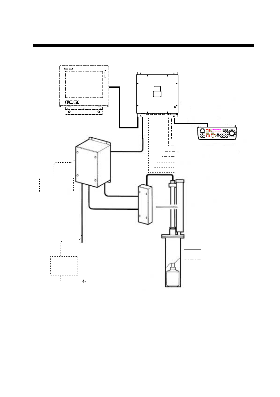
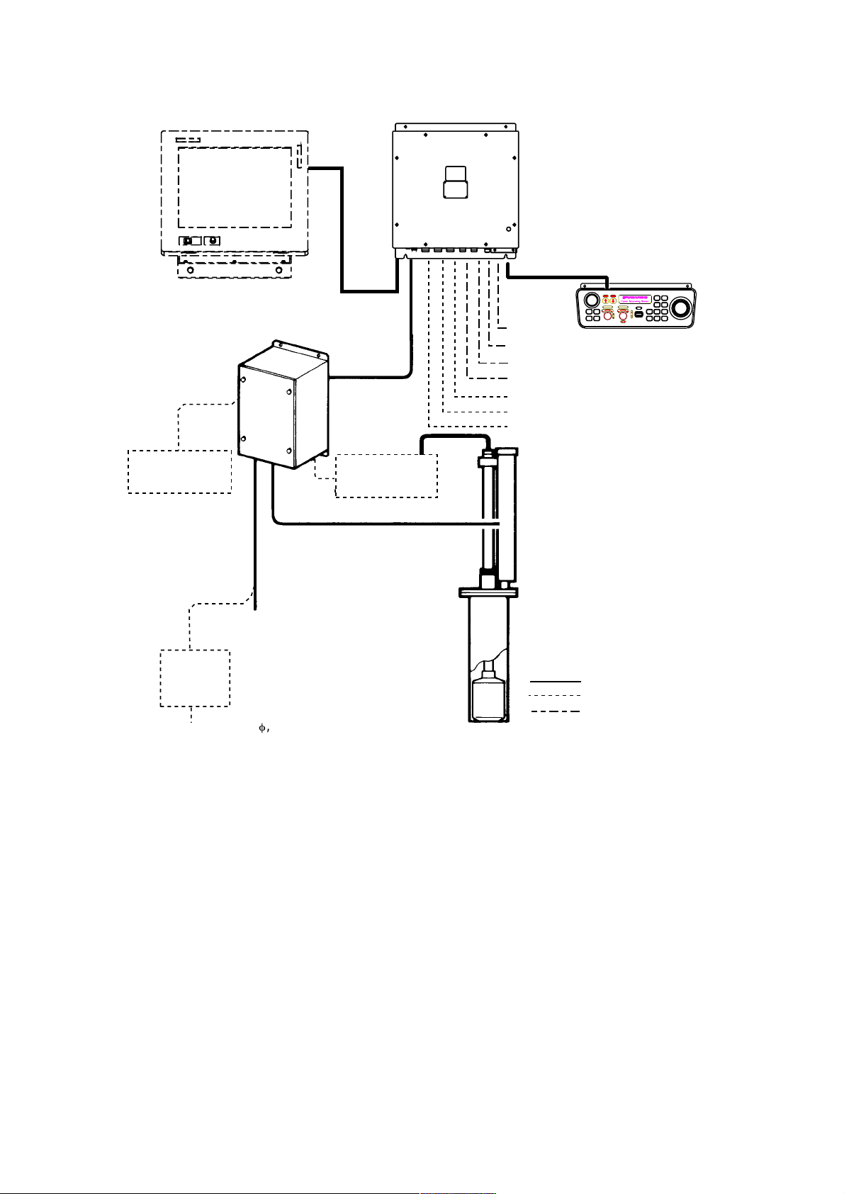
SYSTEM CONFIGURATION
Monitor (MU-150C, etc., Max. 2)
Motion Sensor
MS-100
Processor Unit
CSH-5210
Control Unit
CSH-5211
Transceiver Unit
CSH-5130
Navaid
Current Indicator
AD Converter
Speed Log
E/S Interface
Remote Controller
Speaker
Hull Unit
CSH-5040, 600 mm stroke
CSH-5041, 400 mm stroke
DC/AC
Inverter
TR-2451
24 VDC
Ship's Mains
100 V AC/
115 V AC/
200 V AC/
220 V AC/
240 V AC ,
1
f
, 50-60Hz
Pre-amplifier Unit
CSH-5020
: Standard Supply
: Option
: User Supply
System configuration of CSH-5L
vii
Page 10
Processor Unit
Monitor (MU-150C, etc., Max. 2)
CSH-5210
Control Unit
CSH-5211
Motion Sensor
MS-100
DC/AC
Inverter
TR-2451
24 VDC
Transceiver Unit
CSH-8030
Ship's Mains
100 V AC/
115 V AC/
200 V AC/
220 V AC/
240 V AC ,
1
f
, 50-60Hz
Junction Box
CSH-1700
Navaid
Current Indicator
AD Converter
Speed Log
E/S Interface
Remote Controller
Speaker
Hull Unit
CSH-8040, 600 mm stroke
CSH-8041, 400 mm stroke
: Standard Supply
: Option
: User Supply
System configuration of CSH-8L
viii
Page 11
1. OPERATIONAL OVERVIEW
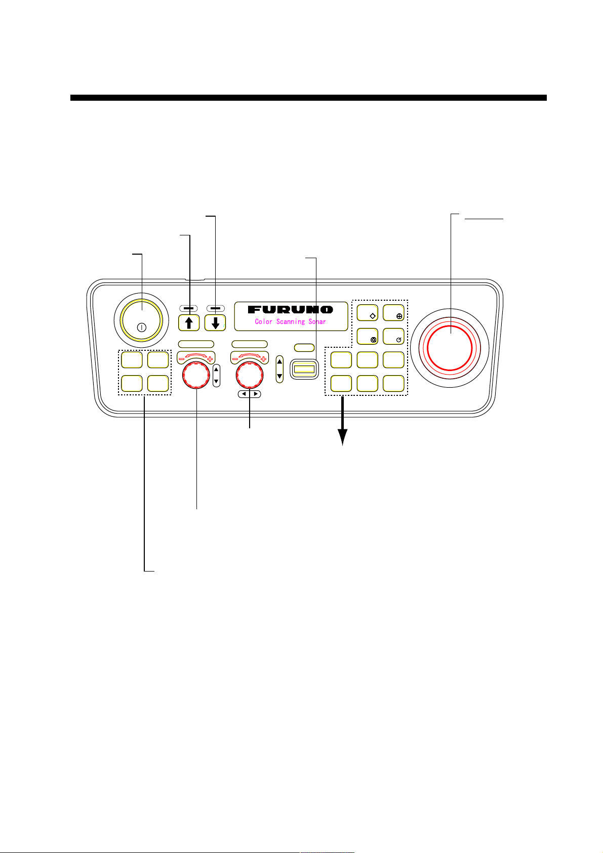
1.1 Control Unit
All operations are carried out from the control unit. All controls quickly respond to
the operator’s command and the associated reaction can be seen on the screen
almost immediately.
Lowers the transducer.
Raises the transducer.
Turns power
on/off.
POWER
F1 F2
F3 F4
Execute assigned
program; register
function key program.
Sets transducer
tilt angle.
RANGE GAIN
Adjusts receiver
sensitivity; chooses
menu option.
Chooses display
range; chooses
menu item.
TILT
Trackball
Positions trackball
mark.
EVENT
FISH
FISH
ALARM
ALARM
ZONE
TARGET
LOCK
STABILIZER
DELETE
MARK
R/B
OFF
CENTER
MENU
FISH: Inscribes fish mark.
EVENT: Inscribes event mark.
TARGET LOCK: Tracks trackball-selected
position.
R/B: Displays range and
bearing marks.
FISH ALARM: Turns fish alarm on/off.
STABILIZER: Compensates for affects
of ship's pitching and
rolling. (Requires Motion
Sensor MS-100.)
OFF CENTER: Shifts the display.
ALARM ZONE: Sets fish alarm zone.
DELETE MARK: Deletes selected mark.
MENU: Opens/closes menu.
Control unit
1-1
Page 12
1. OPERATIONAL OVERVIEW
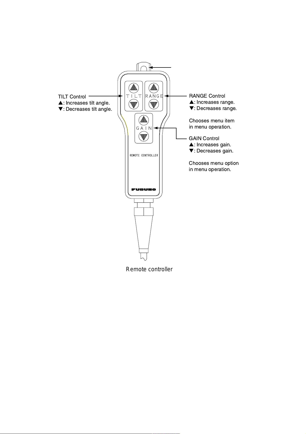
1.2 Remote Controller (option)
The remote controller provides armchair control of the tilt, range, gain and menu
functions.
Hole for hanging
TILT Control
p
: Increases tilt angle.
q
: Decreases tilt angle.
RANGE Control
p
: Increases range.
q
: Decreases range.
Chooses menu item
in menu operation.
GAIN Control
p
: Increases gain.
q
: Decreases gain.
Chooses menu option
in menu operation.
Remote controller
1-2
Page 13

1.3 Basic Operati ng Procedure
1.3.1 Turning on the power
1. Press the POWER switch on the control unit to turn on the power.
2. Turn on the monitor (user supply).
The system initiates the START UP test to check itself for proper operation.
The results are shown as OK or NG (No Good). For any NG, contact your
dealer for advice. After the test is completed, the last-used display appears.
1. OPERATIONAL OVERVIEW
START UP TEST
MAIN-0 1050729-XX.XX F F
ROM = OK
RAM = OK
VRAM = OK
EEPROM (P.W) = OK
TRX 1050742-XX.XX 1050733-XX.XX
ROM = OK
RAM = OK
KEY-0 1050730-XX.XX F
ROM = OK
RAM = OK
Self test screen at start up (example: CSH-5L, 55 kHz transducer)
Note: The example screens shown in this manual may not match the screens
you see on your display. The screen you see depends on your system
configuration and equipment settings.
1.3.2 Lowering the transducer
XX.XX = Program Version No.
Set ship’s speed under 16 knots and then press the [↓] switch. The lamp above
the switch flashes, and lights when the transducer is fully lowered. If you press
the [↓] switch when the speed is over 16 knots and the speed warning is turned
on in the SYSTEM menu, the message “Max allowable speed for extended
transducer is 16 kt. Max allowable speed during raising lowering transducer is 16
kt.” and the audio alarm sounds. Press the [R/B] key to silence the audio alarm.
CAUTION
Do not exceed 18 knots with the
transducer lowered; 16 knots when
lowering the transducer.
The transducer may become damaged.
Note: The audio alarm may be set to sound and a message displayed when the
ship’s speed goes higher than maximum allowable speed. For further
details, see SPEED MESSAGE on page 7-4.
1-3
Page 14
1. OPERATIONAL OVERVIEW
1.3.3 Transmitting
TRANSMISSION in the SONAR menu is off in the default setting. If it is has
been set to ON, the procedure below is not necessary. When the transducer is
lowered, transmission starts and when it is raised transmission is stopped.
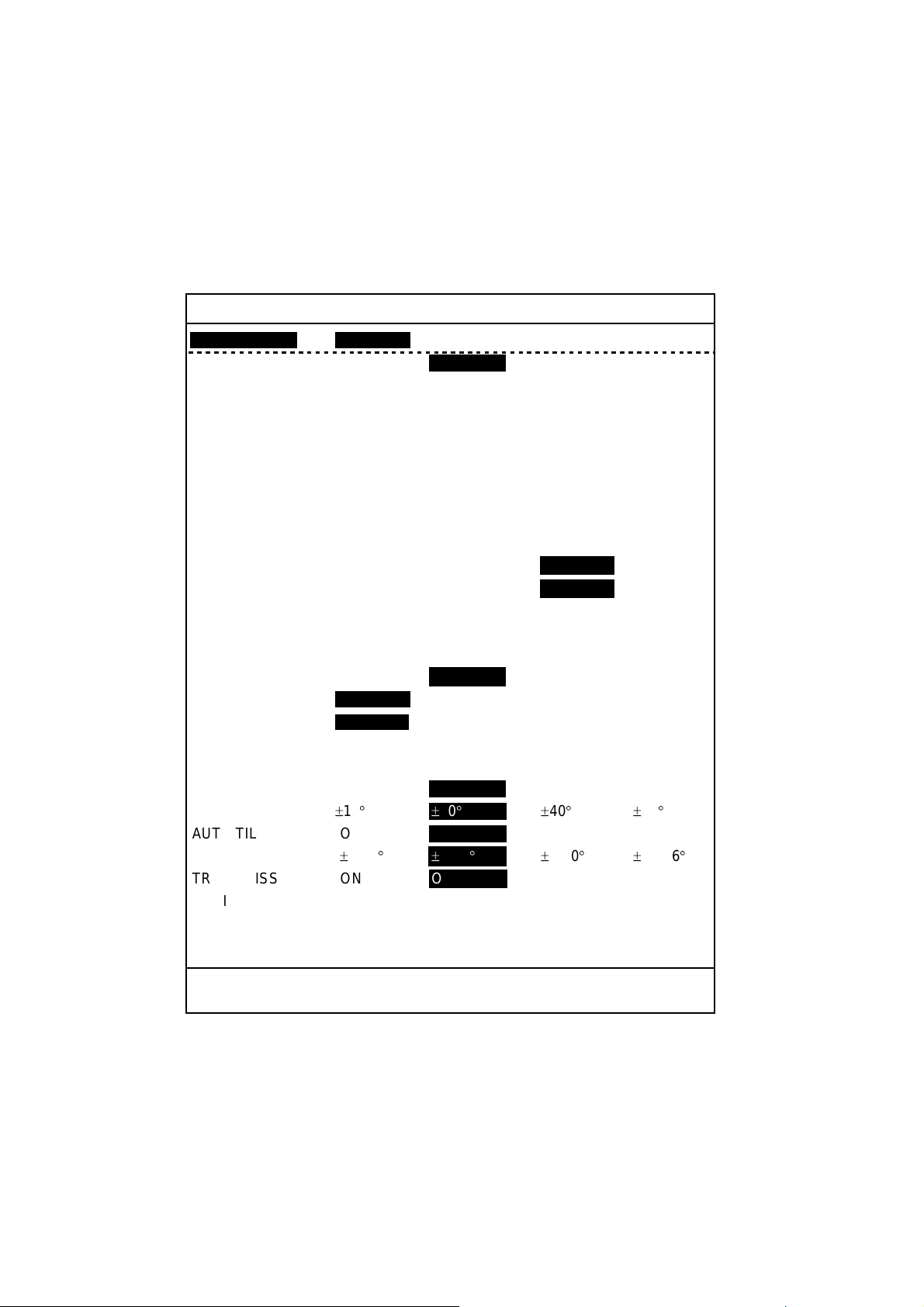
1. Press the [MENU] key to open the menu.
2. Use the [RANGE] control to choose [MENU MODE] at the top of the screen.
3. Use the [GAIN] control to choose SONAR.
SONAR MENU
**
[MENU MODE] : SONAR SOUNDER MARKS SYSTEM
DISPLAY MODE : COMBI-1 NORM COMBI-2
TX OUTPUT : 8
PULSE LENGTH : 8
TX CYCLE : 10
TVG NEAR : 6
TVG FAR : 7
AGC : 2
2ND AGC : 1
NOISE LIMITER : 3
COLOR CURVE : 1 2 3 4
COLOR RESPONSE
DELETE COLOR : 0
ECHO AVERAGE : 1
INT REJECT : 1
HOR BEAMWIDTH : WIDE NARROW
VER BEAMWIDTH : WIDE NARROW
COLOR : 1 234
ERASE MARKS : TRACK SHIP EVENT FISH
ALARM LEVEL : 9
AUT O TRAIN : ON OFF
TRAIN SECTOR : ±10
AUT O TILT : ON OFF
TILT ANGLE :±2-10
TRANSMISSION : ON OFF
AUDIO V OLUME : 10
ASSIGN SETTING : F1 KEY F2 KEY F3 KEY F4 KEY
ASSIGN MENU : EXECUTE
**
:1 2 3 4
° ±20°±
° ±
(RANGE CTRL: U/D, GAIN CTRL: L/R)
40
° ±60°
4-14
°±
6-20
° ±
10-26
°
PRESS [MENU] KEY TO EXIT
SONAR menu
4. Use the [RANGE] control to choose TRANSMISSION.
5. Use the [GAIN] control to choose ON. The sonar starts transmitting and the
sonar picture appears.
6. Press the [MENU] key to close the menu.
To turn off transmission, choose OFF at step 5. “TX OFF” appears at the top
right corner of the sonar display when the transmitter is turned off.
1-4
Page 15
1.3.4 Adjusting backlighting of control unit
1. Press the [MENU] k ey to open the menu.
2. Use the [RANGE] control to choose [ME NU MODE] at the t op of the screen.
3. Use the [GAIN] control to choose SYSTEM.
1. OPERATIONAL OVERVIEW
SYSTEM MENU
**
[MENU MODE] : SONAR SOUNDER MARKS SYSTEM
DIMMER : 10
DISP SELECT : TEMP CURRENT
HEADING ADJ : 0
AUTO RETRACT : OFF (OFF, 5-16kt)OFF
SPEED MESSAGE : ON OFF
EXT KP SYNC : OFF ON
AUTO TRAIN SPD : LOW HIGH
AUTO TILT SPD : LOW HIGH
UNIT : METERS FEET FATHOMS PA/BRA
SHIP'S SPD/BR :
LOG PULSE : 200 400
PORT1 BAUDRATE : 19200 9600 4800 2400
PORT1 FORMAT : NMEA CIF
PORT2 BAUDRATE : 19200 9600 4800 2400
PORT2 FORMAT : NMEA CIF
NAV DATA : GPS LC DR ALL
COMBI SCALE : RIGHT LEFT
SUB TEXT INDI : OFF ON
LANGUAGE : ENGLISH (JAPANESE) ESPANOL DANSK
TEST : SINGLE CONTI PANEL COLOR
SET TO DEFAULT : EXECUTE
**
°
LOG/GYRO
NEDERLND FRANCAIS ITALIANO
NORSK
: PATTERN SIO ECHO-1 ECHO-2
ECHO-3 ECHO-4
(RANGE CTRL: U/D, GAIN CTRL: L/R)
CURRENT NAV DATA
GYRO+NAV
(KOREAN)
PRESS [MENU] KEY TO EXIT
System menu
4. Use the [RANGE] control to choose DIMMER.
5. Operate the [GAIN] control adj us t the dimmer. The s etting range is 0-10.
Adjust t he c ontrol clockwise to incr eas e bac k lighting; counterclockw ise to
decrease it.
6. Press the [MENU] k ey to close the m enu.
1-5
Page 16
1. OPERATIONAL OVERVIEW
1.3.5 Choosi ng a display mode
Three display modes are available: NORMAL, COMBI-1 and COMBI-2. To
choose the display mode, do the following:
1. Press the [MENU] key to open the menu. The last-used menu is displayed.
2. Use the [RANGE] control to choose [MENU MODE] at the top of the screen.
3. Use the [GAIN] key to choose SONAR.
4. Use the [RANGE] control to choose DISPLAY MODE.
5. Use the [GAIN] control to choose desired mode among COMBI-1, NORM
and COMBI-2.
6. Press the [MENU] key to close the menu.
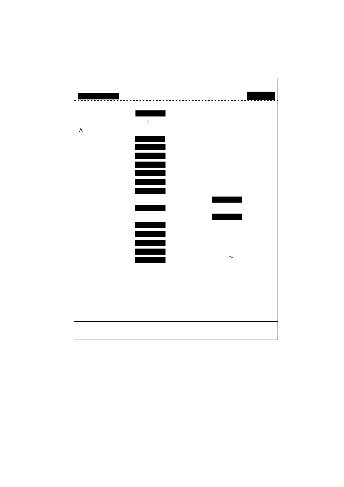
Mode description
Mode Description Display
NORM
(Sonar
display)
COMBI-1
(Sonar +
Audio)
COMBI-2
(Sonar +
echosounder)
This mode is useful for detecting
and tracking fish schools.
Navigation data can be displayed
in the text window, with
connection of appropriate
sensors.
Sonar picture appears on the left
and the audio display at the lower
right side of the screen. This
mode is useful analyzing echoes
in a desired area.
To activate the COMBI-1 mode,
do the following:
1. Choose the COMBI-1 mode.
2. Use the trackball to place the
trackball mark (+) on the
bearing desired.
3. Press the [R/B] key. The range
and bearing marks are
inscribed on the sonar picture,
and the signal along the
bearing mark appears in the
audio display.
The sonar picture appears on the
left and the signal fed from the
echosounder at the lower right
side of the screen. This mode is
suitable for judging fish school
concentration.
Text window
Sonar display
Range and bearing marks
Text window
Audio display
Sonar display
Text window
Echosounder
display
Sonar display
1-6
Page 17
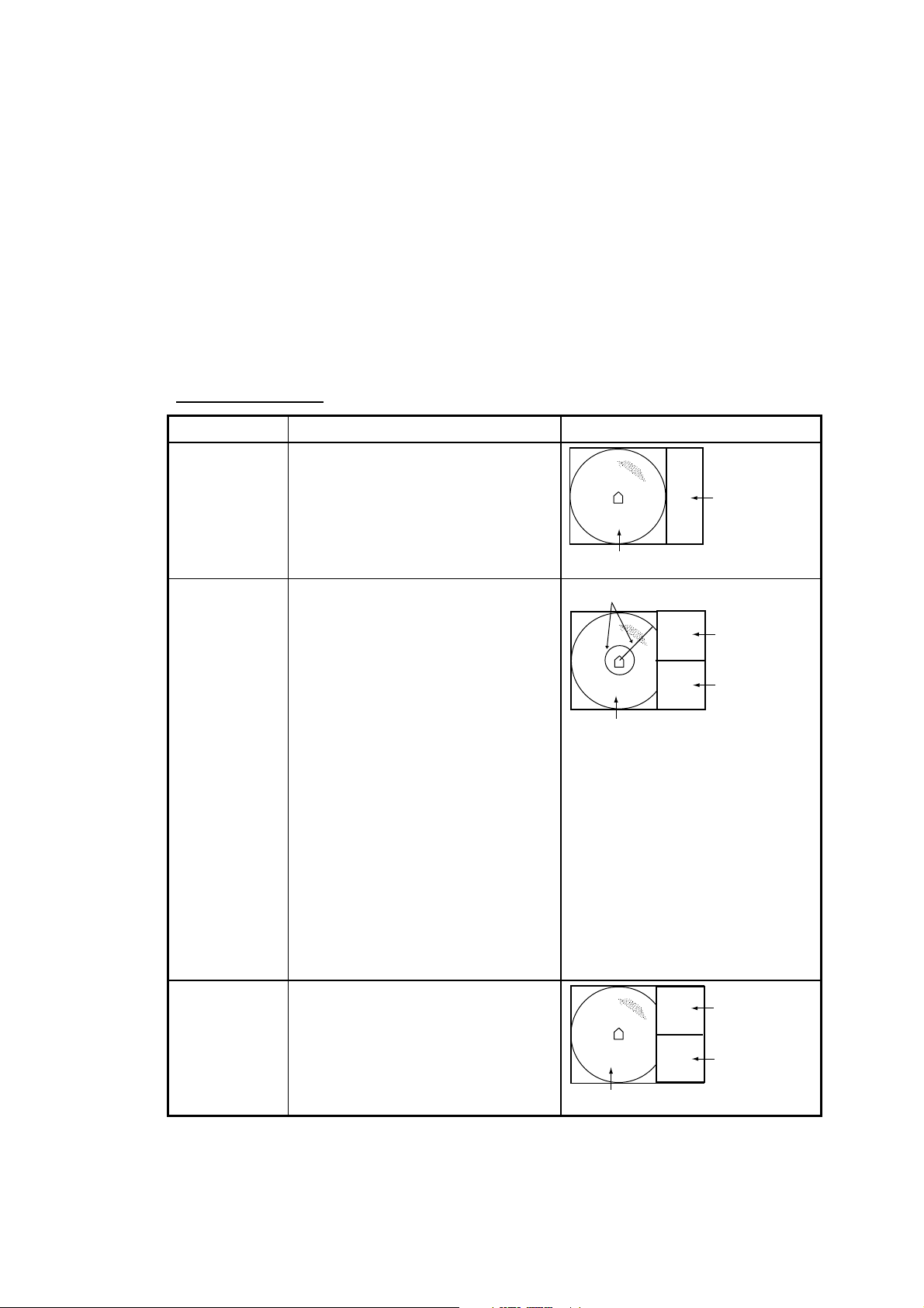
Normal mode display (sonar display)
1. OPERATIONAL OVERVIEW
733
708
189
B 60S
W
500
N
N
S
SHIP SPEED
R 1000
SHIP COURSE
°
T 15
(15)
LAT/LON
G 10.0
132°12.150E
DEPTH
WATER CURRENT
E
WATER TEMP
14
12
10
12.4 kt
246
°
32°52.150N
126m
C1 1.2kt 342
C2 0.8kt 298
C3 0.4kt 256
12.4°C
20min 10 0
°
°
°
Text Window
For description see
Chapter 5.
Sonar display
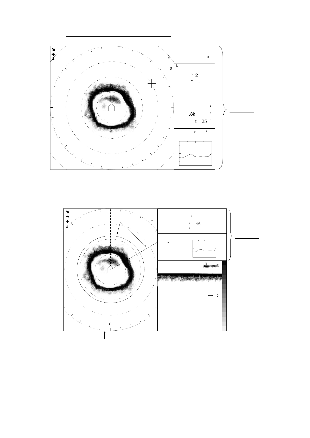
COMBI-1 display (sonar display + audio display)
517
500
134
B 60S
W
N
N
Range &
Bearing Marks
500
S
R 517 B 60S
R 1000
T 15
(15)
G 10.0
Range and bearing marks data
SHIP SPEED
SHIP COURSE
°
LAT/LON
132°12.150E
WATER TEMP
12.4°C
E
12.4 kt
246
°
32°52.150N
20min 10 0
14
12
10
Range Scale
DEPTH
-
126m
0
500 -
1000-
Text Window
For description see
Chapter 5.
-
-
COMBI-1 display (sonar display + audio display)
1-7
Page 18
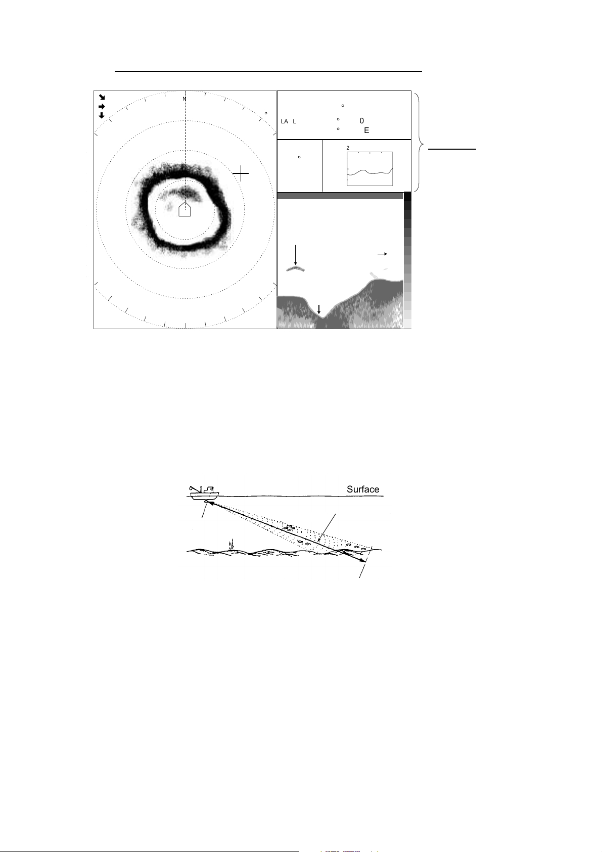
1. OPERATIONAL OVERVIEW
COMBI-2 display (sonar display + echosounder display)
545
472
272
B 60S
N
N
500
S
R 1000
°
T 30
(30)
G 10.0
SHIP SPEED
SHIP COURSE
LAT/LON
132°12.150E
WATER TEMP
12.4°C
E
Fish School
COMBI-2 display (sonar display + echosounder display)
1.3.6 Choosi ng the di splay range
12.4 kt
246
°
32°52.150N
14
12
10
Depth Scale
Bottom
DEPTH
20min 10 0
126m
0
-
100 -
-
200 -
Text Window
For description see
Chapter 5.
-
-
The [RANGE] control chooses a display range. Each time the range is changed
the newly selected range appears in large characters for five seconds at the top
of the sonar display. The current range is always displayed at the top right corner
of the sonar display. The ranges (in meters) available are 50, 85, 100, 150, 200,
250, 300, 350, 400, 450, 500, 600, 800, 1000, 1200 and 1600.
SEA SURFACE
BOTTOM
Bottom
Surface
Range indicated
Range displayed
on the screen.
on screen
Detection range
1-8
Page 19
1.3.7 Adjusting the gain
The [GAIN] control adjusts receiver sensitivity. It should be adjusted to see fish
echoes clearly with minimal noise on the screen. Too high a setting not only
causes excessive noise on the screen and makes it difficult to discriminate
wanted fish echoes but also causes bottom echoes to be painted in strong colors,
resulting that the echoes from bottom fish are masked by bottom reflections. A
setting between 3 and 7 is usually suitable. Each time the control is operated the
newly selected range appears in large characters for five seconds at the top of
the sonar display. The current range is always displayed at the top right corner of
the sonar display.
1. OPERATIONAL OVERVIEW
Gain too low
Examples of proper and improper gain
Gain proper
Gain too high
1.3.8 Retracting the transducer, turning off the power
1. Set speed under 16 knots and then press the [↑] switch to retract the
transducer. The lamp above the switch blinks while the transducer is being
retracted. Transmission is stopped automatically. If you press the [↑] switch
when the speed is over 16 knots and the speed warning is turned on in the
SYSTEM menu, the message “Max allowable speed for extended transducer
is 16 kt. Max allowable speed during raising lowering transducer is 16 kt.”
and the audio alarm sounds. Press the [R/B key to silence the audio alarm.
2. When the lamp above the [↑] switch lights, meaning the transducer is
completely retracted, press the [POWER] switch on the control unit to turn off
the power.
3. Turn off the monitor.
Note 1: The transducer is automatically retracted into the tank whenever the
power switch is turned off. However, for safety purposes, make it a habit
to retract the transducer before turning off the power.
Note 2: The equipment can be set to automatically retract the transducer when
the ship exceeds the operator-set speed. (Speed data required.) The
transducer may be retracted at a different speed than set if the speed
data is different from actual speed. In all cases, reduce the speed below
16 knots and then retract the transducer.
1-9
Page 20
1. OPERATIONAL OVERVIEW
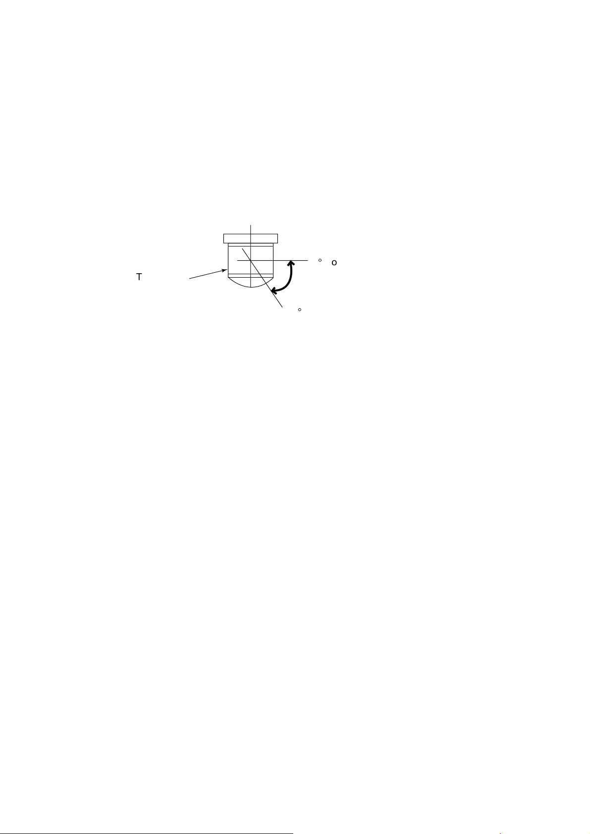
1.4 Setting the Tilt Angle
The tilt angle shows the direction to which the sound wave is emitted. When the
sound wave is emitted horizontally, it is said to be zero (0) degrees and when
emitted vertically, 90 degrees.
To set a tilt angle, operate the TILT lever for the desired angle while watching the
tilt angle indication at the top right corner of the sonar display. Each time the
lever is operated the newly selected tilt angle is displayed in large characters for
five seconds at the top of the sonar display. The tilt angle can be set in
one-degree steps within the range of 0 to 55 degrees.
Transducer
+55
0°Horizontal direction (tilt: 0)
Tilt angle range
°
1.4.1 Automatic tilt on/off
The automatic tilt feature automatically tilts the transducer within the tilt range
selected on the menu. This feature is useful for finding fish school center.
Automatic tilt becomes inoperative when the target lock feature is made active.
Disable the target lock feature to resume automatic tilt.
1. Press the [MENU] key to open the menu.
2. Operate the [RANGE] control to choose [MENU MODE] at the top of the
screen.
3. Operate the [GAIN] control to choose SONAR.
4. Operate the [RANGE] control to choose AUTO TILT.
5. Operate the [GAIN] control to choose ON.
6. Operate the [RANGE] control to choose TILT ANGLE.
7. Use the [GAIN] control to choose a tilt range among ±2-10°, ±4-14°, ±6-20°,
and ±10-26°. See the table on the next page for range and tilt angle.
8. Press the [MENU] key to close the menu. When auto tilt is on, auto tilting
begins with the range selected (at step 7), centered on the tilt angle set with
the TILT lever.
To turn off automatic tilt, choose OFF at step 5. Note that automatic tilt range
varies with the range in use.
Tilt range
1-10
Page 21
Range and tilt angle
1. OPERATIONAL OVERVIEW
Range (m) ±2-10°
50, 85, 100, 150, 200, 250, 300, 350
400, 450, 500
600, 800
1000, 1200, 1600
±10°
±8°
±6°
±2°
±4-14°
±14°
±12°
±10°
±4°
±6-20°
±20°
±16°
±14°
±6°
±10-26°
±26°
±20°
±20°
±10°
For example, when the [RANGE] control, [TILT] lever and automatic tilt are set to
°
1000 m, 8
and ±2-10° respectively, the tilt angle changes at each transmission
as follows:
° → 10° → 8° → 6° → 8° → ...
8
Tilt Angle
Auto tilt concept
1-11
Page 22
1. OPERATIONAL OVERVIEW
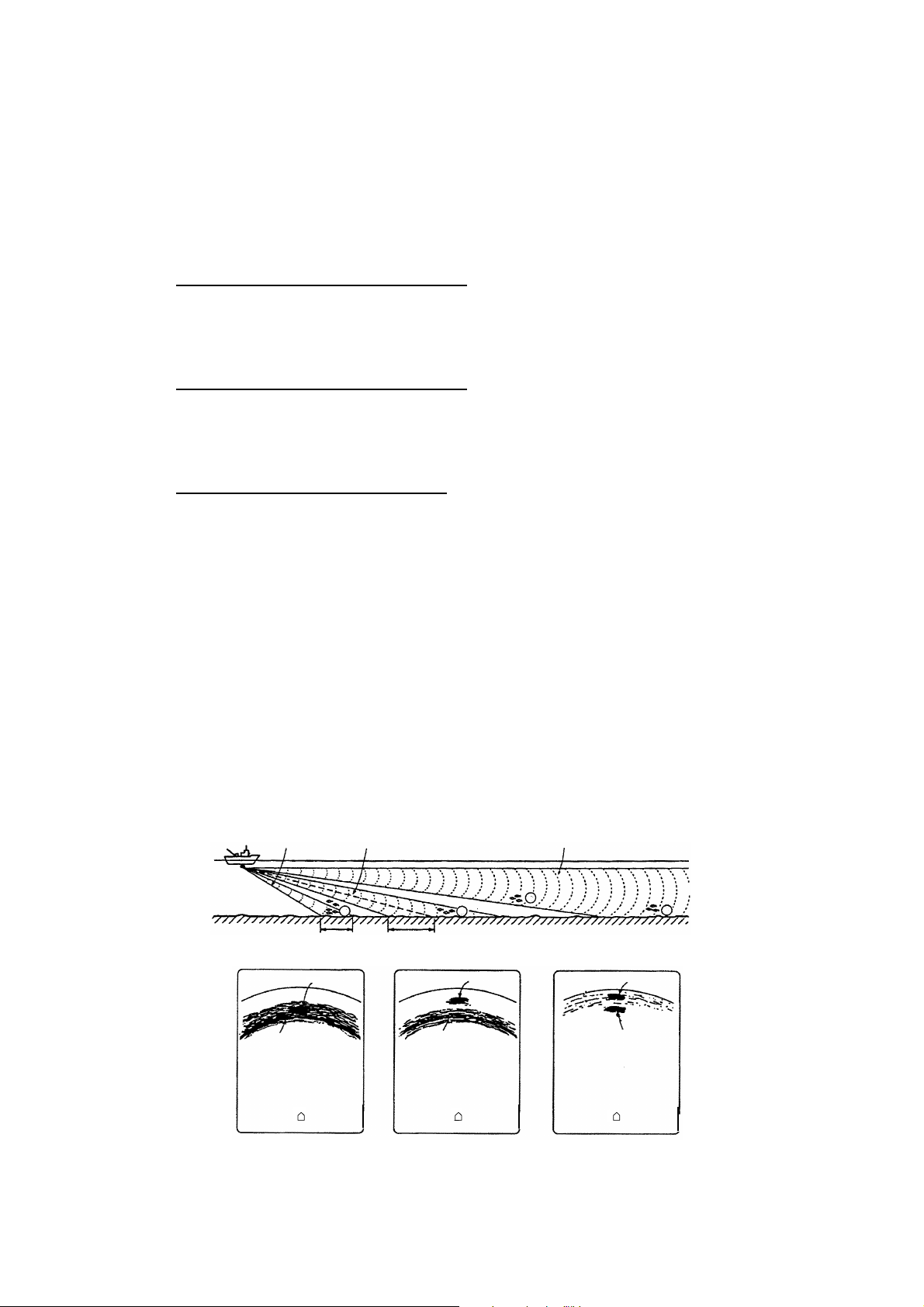
1.4.2 Bottom and tilt angle
Finding the proper tilt angle is of utmost importance when searching for fish,
especially in coastal water fishing, where the depth of the fishing ground is from
50-100 m. In this type of fishing ground it is imperative that the bottom echo be
always displayed to properly distinguish between fish and the bottom. When
selecting a tilt angle, keep the following points in mind.
Case 1: Tilt angle 30 to 40 degrees
This tilt angle uses the full beamwidth to receive echoes, thus the entire bottom
echo is displayed. Fish echoes may be hidden in the bottom echo.
Case 2: Tilt angle 10 to 20 degrees
This tilt angle receives bottom echoes within the bottom half of the beam. Fish
echoes astern of the bottom echo are displayed.
Case 3: Tilt angle 0 to 5 degrees
This tilt angle may or may not display returning echoes. Fish echoes near the
bottom echo are displayed.
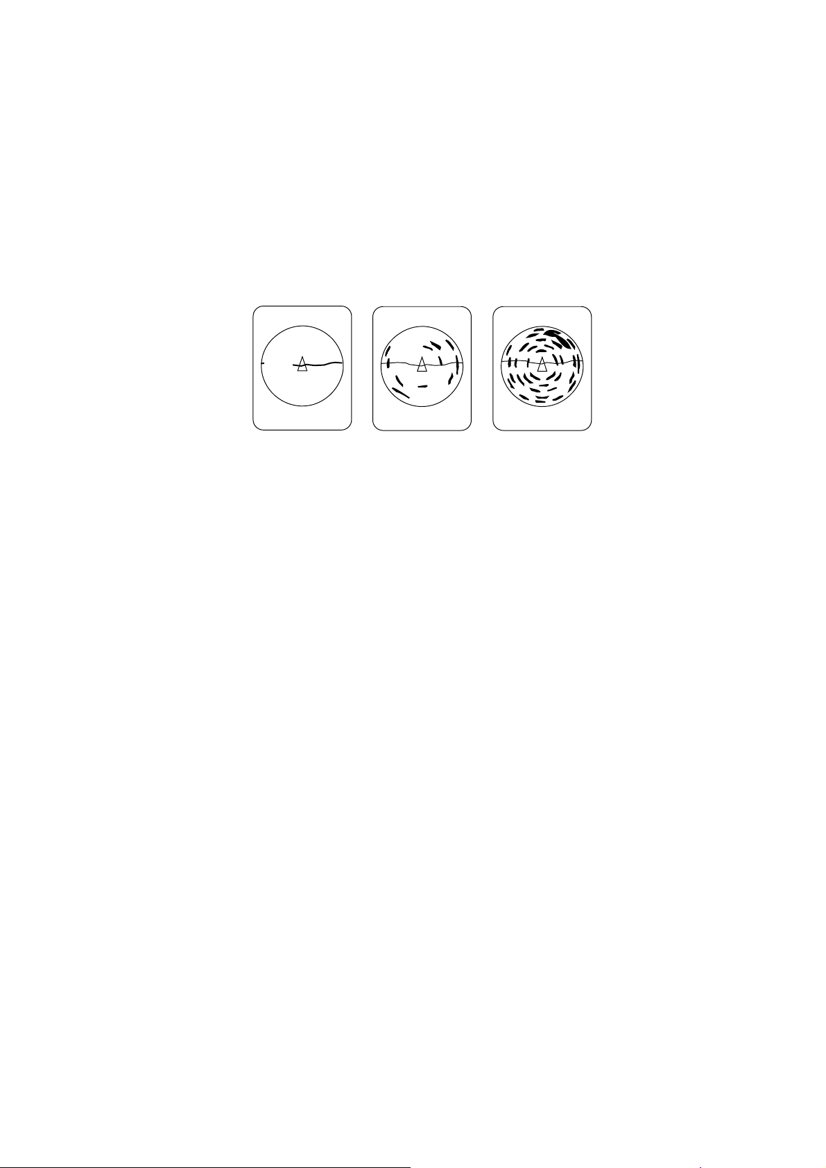
1.4.3 How to discriminate fish echoes from the bottom
The following figure illustrates how two fish schools (a) and (b) are displayed on
screen using three different tilt angles.
Case 1: Tilt angle 30 to 40 degrees
Fish school is obscured by the bottom echo.
Case 2: Tilt angle 10 to 20 degrees
Fish school is located above the bottom echo (midwater).
Case 3: Tilt angle 0 to 5 degrees
Fish school is located close to the bottom echo.
Case 1 Case 2 Case 3
a
a
b
a
1-12
Fish school (a) Fish school (a) Fish school (a)
Bottom
Bottom Bottom
Case 1 Case 2 Case 3
(b)
How to discriminate fish echoes from bottom
Page 23
1.4.4 Points to consider
•
As a general rule of thumb, a vertically distributed fish school is a better sonar
target than a horizontally one, since it reflects the transmitted pulse back
toward to the source.
•
In case 3, both fish schools (a) and (b) are presented. Generally speaking,
however, midwater fish schools tend to be larger than bottom fish schools and
they are often displayed near the bottom on the sonar screen.
•
Detection of bottom fish is difficult if they are not distributed vertically.
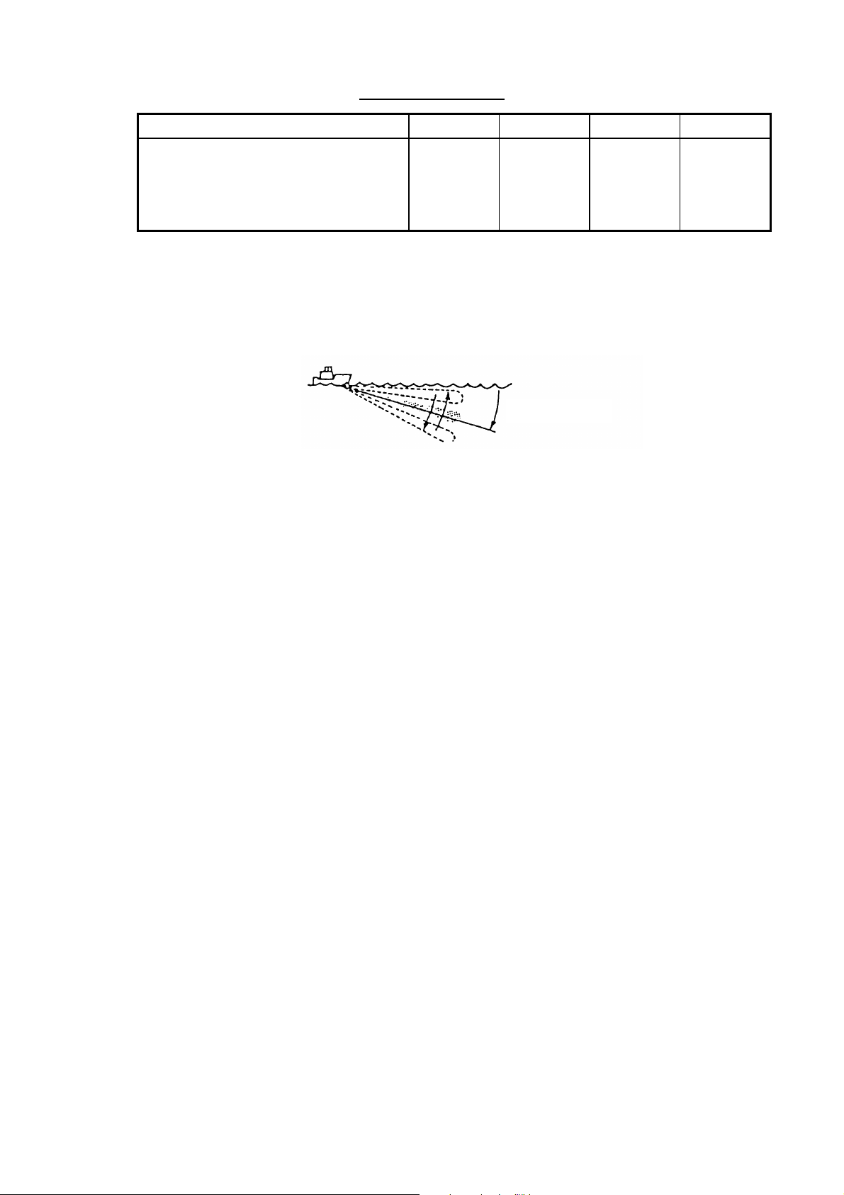
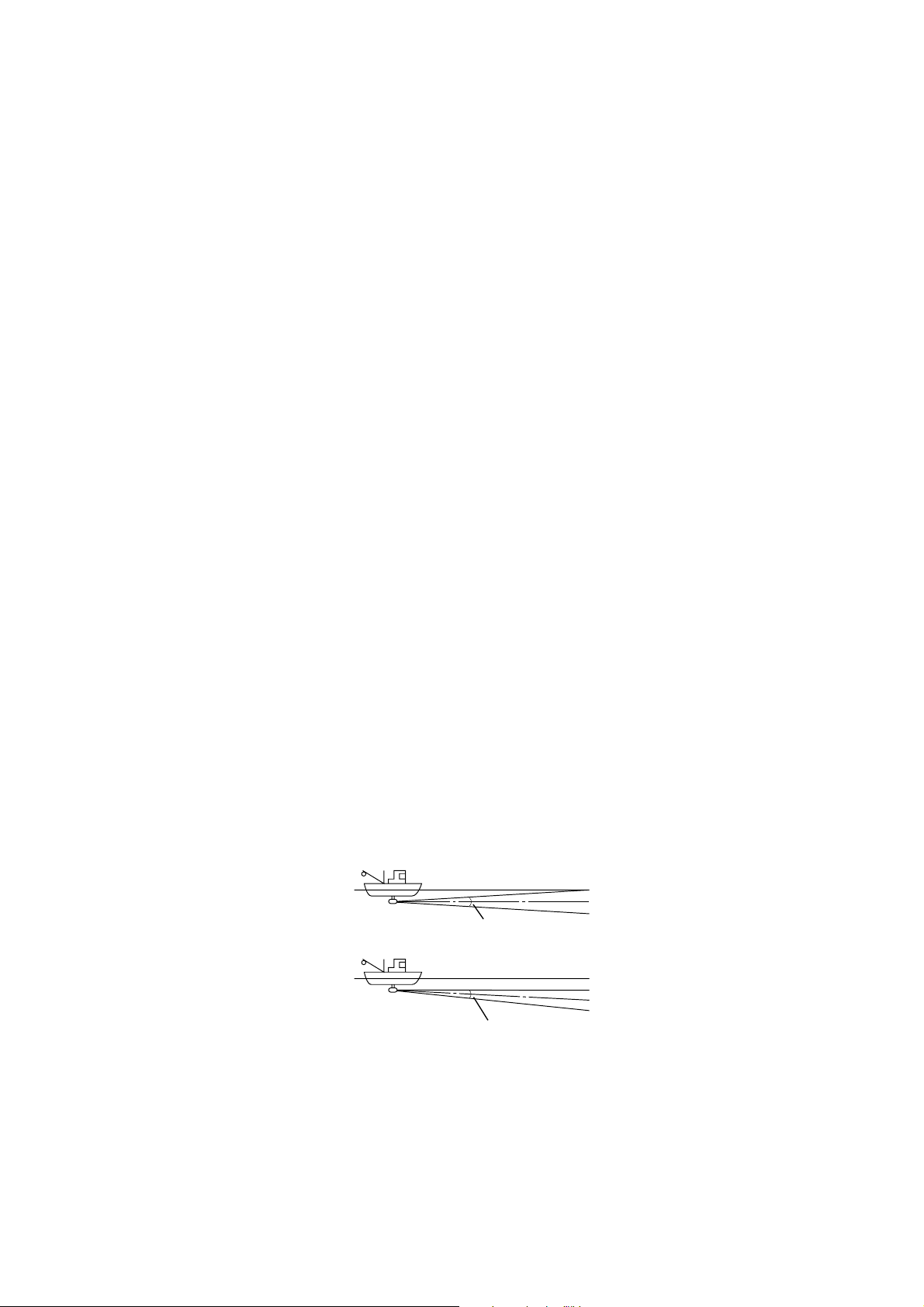
1.4.5 Tilt angle for surface fish
Sound emitted from the sonar transducer forms a circle-shaped beam with a
width of approximately 15°* (-6dB in the vertical direction). The tilt angle is
indicated by the angle between the center line of the beam and the horizontal
plane. Then, if the tilt angle is set to 0 degrees, the center line is parallel with the
sea surface and one half of the emitted sound goes upward toward the sea
surface.
This causes a half of the emitted sound to be reflected back toward the
transducer and displayed on the screen as sea surface reflections. When the
sea is calm, since the sound is reflected just like a light hitting a mirror at a
narrow incident angle, it propagates away and the sea surface reflections
become negligible.
However if the sea is not calm enough, they will become dominant and will
interfere with observation of wanted echoes. To minimize these sea surface
reflections and to search surface fish schools effectively, the tilt angle is usually
set to 5-6 degrees so that the upper portion of the beam becomes almost
parallel with the sea surface. When the sea is rough, it is often set to a little
larger angle.
* 15° for CSH-5L, 13° for CSH-8L
1. OPERATIONAL OVERVIEW
Sea surface
Tilt angle 0°
Tilt angle 5-6°
Tilt angle and surface fish (example: CSH-5L)
15°
Sea surface
15°
1-13
Page 24
1. OPERATIONAL OVERVIEW
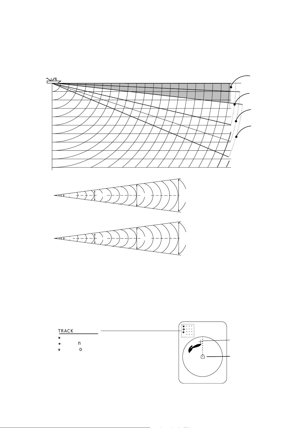
1.4.6 Suitable tilt angle
The table below shows the estimated detection range for tilt angles of 0, 5, 10
and 15 degrees. Refer to the table to find suitable tilt angle from depth and
detection range.
Tilt angle setting
100
(200)
200
(400)
300
(600)
Detection range (m)
400
(800)
0°
20(40)
40(80)
60(120)
80(160)
100(200)
Depth (m)
200(400)
Vertical width of sonar beam
15°
13°
100 m
100 m
26 m
23 m
200 m
200 m
52 m
46 m
300 m
78 m
300 m
68 m
5°
10°
15°
CSH-5L
CSH-8L
Depth, detection range and tilt angle
1.5 Finding Range and Bearing to a Target
Operate the trackball to place the trackball mark on the target you want to
measure the range and bearing. The slant range, horizontal range, bearing and
depth to the target appear at the upper left corner of the sonar display.
î
TRACKBALL DATA
î
Slant range from own ship to trackball mark
è
Horizontal range from own ship to trackball mark
ê
Depth to trackball mark
B Relative from own ship to trackball mark*
* = Relative bearing format may be selected with
OTHER MARKS on the MARKS menu.
Location of trackball data
è
ê
B
Trackball mark
Own ship mark
1-14
Page 25
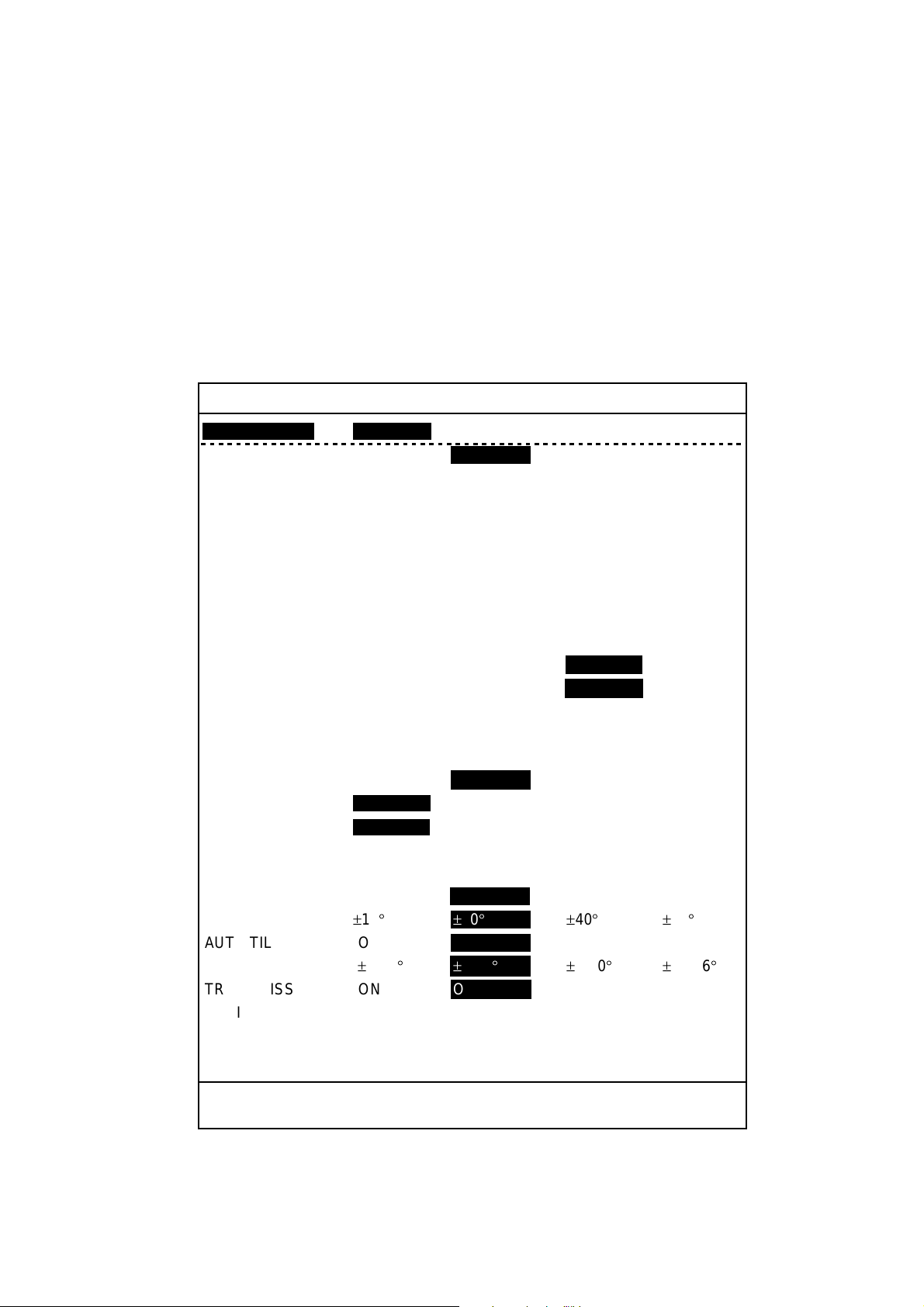
1.6 Sonar Menu Overview
This equipment has four menus: sonar menu, sounder menu, marks menu and
system menu. Of the four menus, the SONAR menu is the one you will use most
often.
Note that the gain and range cannot be adjusted while the menu is displayed.
1.6.1 Operating procedure
1. Press the [MENU] key. The last-used menu appears.
2. Use the [RANGE] control to choose [MENU MODE] at the top of the screen.
3. Use the [GAIN] control to choose SONAR to display the SONAR menu.
1. OPERATIONAL OVERVIEW
SONAR MENU
**
[MENU MODE] : SONAR SOUNDER MARKS SYSTEM
DISPLAY MODE : COMBI-1 NORM COMBI-2
TX OUTPUT : 8
PULSE LENGTH : 8
TX CYCLE : 10
TVG NEAR : 6
TVG FAR : 7
AGC : 2
2ND AGC : 1
NOISE LIMITER : 3
COLOR CURVE : 1 2 3 4
COLOR RESPONSE
DELETE COLOR : 0
ECHO AVERAGE : 1
INT REJECT : 1
HOR BEAMWIDTH : WIDE NARROW
VER BEAMWIDTH : WIDE NARROW
COLOR : 1 234
ERASE MARKS : TRACK SHIP EVENT FISH
ALARM LEVEL : 9
AUT O TRAIN : ON OFF
TRAIN SECTOR : ±10
AUT O TILT : ON OFF
TILT ANGLE :±2-10
TRANSMISSION : ON OFF
AUDIO V OLUME : 10
ASSIGN SETTING : F1 KEY F2 KEY F3 KEY F4 KEY
ASSIGN MENU : EXECUTE
**
:1 2 3 4
° ±20°±
° ±
(RANGE CTRL: U/D, GAIN CTRL: L/R)
40
° ±60°
4-14
°±
6-20
° ±
10-26
°
PRESS [MENU] KEY TO EXIT
Sonar menu
1-15
Page 26
1. OPERATIONAL OVERVIEW
4. Use the [RANGE] control to choose a menu item. The selected item is
highlighted.
Note: Items displayed in red are locked to prevent accidental change of
setting. When any of those items are selected the display shown
below appears, to ask you if you are sure to change the setting. To
change the setting, use the [GAIN] control to choose YES and then
press the [EVENT] key. The items colored in red turn green to show
that they are available for adjustment.
SELECTED MENU IS LOCKED
ARE YOU SURE TO CHANGE? NO YES
PRESS [EVENT] KEY TO EXECUTE
5. Use the [GAIN] control to choose the option desired.
6. To close the menu, press the [MENU] key.
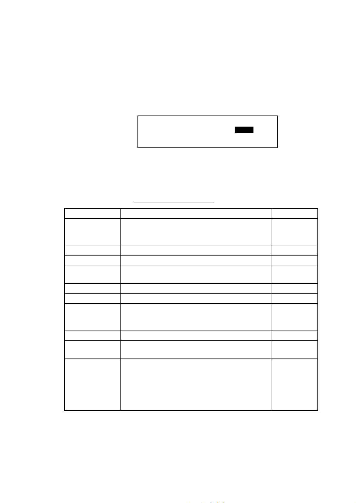
1.6.3 Sonar menu descripti on
Description of sonar menu
Item Description Ref. page
DISPLAY MODE Chooses the display mode among, COMBI-1
(NORM + Audio), NORM (Sonar) and
COMBI-2 (NORM + Echosounder).
TX OUTPUT Adjusts transmitter power. 2-4
PULSE LENGTH Chooses pulse length. 2-3
TX CYCLE Removes interference caused by other sonars
operating nearby.
TVG NEAR Adjusts receiving gain within 300 m. 2-1
TVG FAR Adjusts receiver gain beyond 300 m. 2-1
AGC Automatically reduces the receiver gain only
against strong echoes such as the bottom or a
large fish school, to suppress bottom tail.
2ND AGC Suppresses bottom echo. 2-3
NOISE LIMITER Suppresses unwanted reflections caused by
sediments in water, plankton or ship’s noise.
COLOR CURVE Adjusts echo presentation color curve against
strong reflections. In setting “1,” for example,
weak to strong signals are averaged and
displayed to obtain a balanced picture. The larger
the setting the better the resolution on weak
signals.
1-6
2-6
2-2
2-5
—
1-16
Page 27

1. OPERATIONAL OVERVIEW
Description of sonar menu (con’t from previous page)
Item Description Ref. page
COLOR
RESPONSE
DELETE
COLOR
ECHO
AVERAGE
INT REJECT Rejects random noise and sea surface reflections in
HOR
BEAMWIDTH
VER
BEAMWIDTH
COLOR Chooses display colors for the sonar and audio
ERASE MARKS Chooses the mark type to erase collectively, from
ALARM LEVEL Sets echo strength level which triggers the fish
AUTO TRAIN Turns automatic transducer training on or off. 3-3
TRAIN SECTOR Chooses train sector in automatic training. 3-3
AUTO TILT Turns automatic tilt on or off. 1-10
TILT ANGLE Sets automatic tilt range. 1-10
TRANSMISSION Turns transmission on or off. 1-4
AUDIO
VOLUME
ASSIGN
SETTING
ASSIGN MENU Displays programs assigned to function keys. 3-12
Adjusts color level against strong reflections. The
higher the setting, the more the red color is
displayed and weak level colors are displayed as is,
thereby giving the appearance that the gain has
been raised.
Erases desired echo level from the display. 2-7
Specifies how long to leave afterglow on the screen. 2-7
rough sea conditions.
Sets horizontal beamwidth for wide or narrow. 2-7
Sets vertical beamwidth for wide or narrow. 2-7
displays, among four choices. Choose a display
color to match your environment or fishing objective.
track, own ship, event and fish. For track, 10% of
the oldest track is erased.
alarm. The lower the setting the weaker the echo
which triggers the alarm.
Sets audio volume of loudspeaker. 3-3
Chooses function key to program. 3-10
—
2-5
—
3-9
3-4
1-17
Page 28

1. OPERATIONAL OVERVIEW
(This page intentionally left blank.)
1-18
Page 29

2. FINE TUNING THE SONAR PICTURE
2.1 Eliminating Unwanted Echoes
Echoes from targets such as bottom and fish return to the transducer in order of
distance to them, and when we compare their intensities at the transducer face,
those from nearer targets are generally stronger when their reflecting properties
are nearly equal. The sonar operator will be quite inconvenienced if these
echoes are directly displayed on the screen, since the actual size of the target
cannot be judged from the size of echoes displayed on the screen. To overcome
this inconvenience, the TVG function is incorporated. It compensates for
propagation loss of sound in water; amplification of echoes on short rang is
suppressed and gradually increased as range increases so that similar targets
are displayed in the similar intensities irrespective of the ranges to them.
The CSH-5L/CSH-8L incorporates two TVG functions, NEAR and FAR, and they
mainly compensate for propagation loss on short and long ranges respectively,
centered at the ranges shown below.
NEAR
300 m
How TVG works
The TVG is also used to suppress unwanted echoes and noise which appear in
a certain range area on the screen such as sea surface reflections and cruising
noise. To obtain the proper TVG setting, follow the procedure below.
1. Press the MENU key.
2. Use the [RANGE] control to choose [MENU MODE] at the top of the screen.
3. Use the [GAIN] control to choose SONAR to display the SONAR menu.
4. Use the [RANGE] control to choose TVG NEAR.
5. Use the [GAIN] control to adjust gain.
6. Use the [RANGE] control to choose TVG FAR.
7. Use the [GAIN] control to adjust TVG FAR (setting range: 0-10).
8. When sea surface reflections or plankton layers disturb the picture, adjust
TVG NEAR to eliminate them. They will be eliminated by decreasing the
setting by “1” or “2.”
FAR
2-1
Page 30

2. FINE TUNING THE SONAR PICTURE
8. On a long range, locate a fish school which is approaching own ship. Note
that the tilt should be kept adjusted so that the fish school is always placed in
the center of the sonar beam, i.e., so that the fish school is displayed in
strongest colors possible. Check that the fish echo is displayed in the same
color while it approaches. If the color changes suddenly to weaker colors as
the fish echo enters FAR and NEAR areas, the TVG is improperly set. Adjust
the TVG to correct it. If this again produces sea surface reflections and noise,
try to remove them with the AGC and noise limiter as described later on.
9. Press the [MENU] key to close the menu.
2.2 Displaying Surface Fish Clearly
When you are searching for surface fish with the tilt set to a narrow angle, sea
surface reflections may disturb or mask wanted fish echoes. In this case, in
addition to the TVG adjustment described earlier, adjust AGC on the SONAR
menu. Normally set it between “0” and “3.”
2.3 Suppressing Bottom Tail
As noted earlier, fish schools (echoes) located near the bottom are sometimes
difficult to detect because you have to discriminate them from the bottom
reflections. AGC, PULSE LENGTH and 2ND AGC in the SONAR menu, if used
properly, decrease the tail of bottom reflections, making it easier to discriminate
bottom fish.
2.3.1 AGC
The AGC functions to automatically reduce the receiver gain only against strong
echoes such as the bottom or a large fish school. Since weak echoes remain
unaffected, a small fish school becomes easier to detect. Adjust the AGC so it
works only on bottom reflections.
1. Press the MENU key.
2. Use the [RANGE] control to choose [MENU MODE] at the top of the screen.
3. Use the [GAIN] control to choose SONAR to display the SONAR menu.
4. Use the [RANGE] control to choose AGC.
5. Use the [GAIN] control to set AGC value. The setting range is 0-10 and the
higher the setting the stronger the AGC effect.
6. Press the [MENU] key to close the menu.
2-2
Page 31

2.3.2 Pulse length
The pulse length control determines the length of the transmission pulse emitted
into the water. While a longer pulse is advantageous for long-range sounding, it
has the disadvantage of being poor in discrimination of targets, i.e., ability to
separate several closely located targets. When searching bottom fish, therefore,
it is useful to shorten the pulselength in order to separate fish echoes from
bottom reflections. For search of surface and midwater fish in which bottom
reflections are not so strong, the longest pulse length “10” should be used.
1. Press the MENU key.
2. Use the [RANGE] control to choose [MENU MODE] at the top of the screen.
3. Use the [GAIN] control to choose SONAR to display the SONAR menu.
4. Use the [RANGE] control to choose PULSE LENGTH.
5. Use the [GAIN] control to set pulse length. The setting range is 0-10 and the
higher the setting the longer the pulse length.
6. Press the [MENU] key to close the menu.
2.3.3 2ND AGC
While it is ideal to suppress bottom echoes with the AGC alone there are some
fishing grounds where this is not possible. (The high power sonar has the
advantage of long-range detection but this can also be a disadvantage, since
weaker echoes may be hidden in strong, unwanted echoes such as the bottom.)
If you cannot suppress bottom echoes or sea surface reflections by the AGC
function alone, use the 2ND AGC feature. Normally a setting of 1 or 2 is suitable.
For especially strong echoes, use a setting of 3 or 4.
1. Press the MENU key. The last-used menu appears.
2. Use the [RANGE] control to choose [MENU MODE] at the top of the screen.
3. Use the [GAIN] control to choose SONAR to display the SONAR menu.
4. Use the [RANGE] control to choose 2ND AGC.
5. The 2ND AGC setting is locked so use the [GAIN] control to choose YES and
then press the [EVENT] key.
6. Use the [GAIN] control to set 2ND AGC. The setting range is 0-10 and the
higher the setting the greater the 2ND AGC effect.
7. Press the [MENU] key to close the menu.
2-3
Page 32

2. FINE TUNING THE SONAR PICTURE
2.4 Suppressing Bottom and Sea Surface Reflections in Shallow Fishing Grounds
In shallow fishing grounds with hard or rocky bottom, bottom reflections often
interfere with wanted fish echoes and they can not be eliminated sufficiently with
the aforementioned TVG and AGC, especially when the tilt angle is large in
order to track fish schools approaching within 400 m. In such cases try to reduce
the output power without turning down the gain. The picture becomes clearer
when the output power is reduced rather than when the gain is decreased as
illustrated below.
1. Press the MENU key. The last-used menu appears.
2. Use the [RANGE] control to choose [MENU MODE] at the top of the screen.
3. Use the [GAIN] control to choose SONAR to display the SONAR menu.
4. Use the [RANGE] control to choose TX OUTPUT.
5. Use the [GAIN] control to set TX output. The higher the setting (setting range:
0-10) the greater the TX power.
6. Press the [MENU] key to close the menu.
For long-range detection, set TX OUTPUT to 10.
Improper
Proper
Bottom echo masks
fish echo.
TVG and AGC
adjusted, OUTPUT
high.
OUTPUT decreased,
gain maintainted
How to adjust TX output
Fish echo
weakened
Fish echo
2-4
Page 33

2. FINE TUNING THE SONAR PICTURE
2.5 Rejecting Sonar Interfer ence and Noise
While observing the sonar picture, you may encounter occasional or intermittent
noise and interference. These are mostly caused by on-board electronic
equipment, engine or propeller noise, or electrical noise from other sonars being
operated nearby.
2.5.1 Identifying noise source
To eliminate noise effectively, you should first identify the noise source.
•
Turn off “TRANSMISSION” in the SONAR menu to stop transmission and
operate all on board equipment one by one while observing the picture.
•
Run the boat at various speeds to check if the noise is speed dependent.
If neither of the above two steps affects on the picture, adjust the INT REJECT
(Interference Rejector), NOISE LIMITER or TX CYCLE on the SONAR menu as
appropriate.
2.5.2 Rejecting noise with the interference rejector
This control is similar to the interference rejector on echo sounders and radars. It
is effective for rejecting random noise and sea surface reflections in rough sea
conditions. Set the interference rejector so that noise is just eliminated. Do not
use an unnecessarily high setting since small wanted echoes may also be
rejected.
1. Press the MENU key.
2. Use the [RANGE] control to choose [MENU MODE] at the top of the screen.
3. Use the [GAIN] control to choose SONAR to display the SONAR menu.
4. Use the [RANGE] control to choose INT REJECT.
5. Use the [GAIN] control to set interference rejection level, from 0 (OFF) to 3
(highest degree of suppression).
6. Press the [MENU] key to close the menu.
2.5.3 Rejecting noise with the noise limiter
Weak, unwanted reflections, colored light blue or green, are displayed when
water is contaminated or plankton layers exist or due to ship’s noise.
1. Press the MENU key. The last-used menu appears.
2. Use the [RANGE] control to choose [MENU MODE] at the top of the screen.
3. Use the [GAIN] control to choose SONAR to display the SONAR menu.
4. Use the [RANGE] control to choose NOISE LIMITER.
5. Use the [GAIN] control to set noise limiter level. The setting range is 0-10 and
the higher the figure the greater the degree of suppression.
6. Press the [MENU] key to close the menu.
2-5
Page 34

2. FINE TUNING THE SONAR PICTURE
2.5.4 Rejecting interference with TX cycle
When other sonars of the same TX frequency as own sonar are near, an
interference ring caused may be displayed. To erase the interference ring from
the screen, reduce the TX CYCLE setting.
Interference
Tx cycle high Tx cycle lowered
Interference rings
1. Press the MENU key.
2. Use the [RANGE] control to choose [MENU MODE] at the top of the screen.
3. Use the [GAIN] control to choose SONAR to display the SONAR menu.
4. Use the [RANGE] control to choose TX CYCLE.
5. Use the [GAIN] control to set TX cycle. The setting range is 0-10 and the
higher the figure the longer the TX cycle.
6. Press the [MENU] key to close the menu.
Note: When the sonar is used in shallow waters with the range set between 100
m and 200 m and the TX cycle at “10”, a previously reflected echo may
appear at close range. In this case reduce the TX cycle to “7 or 8” to
reject it.
2-6
Page 35

2.6 Choosing Beamwidth
2.6.1 Horizontal beamwidth
If you wish to have better bearing discrimination (ability to distinguish two closely
located targets at the same range and different bearings) for fish schools and
also wish to examine the contour of bottom, set HOR BEAMWIDTH to NARROW,
on the SONAR menu.
2.6.2 Vertical beamwidth
For better bearing discrimination in the vertical direction, set VER BEAMWIDTH
to NARROW, on the SONAR menu.
2.7 Deleting Weak Echoes
You can remove weak echoes to clear the picture. Echoes are deleted by
strength so this feature is useful for observing only large fish schools or
suppressing interference.
1. Press the [MENU] key to open the menu.
2. Use the [RANGE] control to choose [MENU MODE] at the top of the screen.
3. Use the [GAIN] control to choose SONAR.
4. Use the [RANGE] control to choose DELETE COLOR.
5. Use the [GAIN] control to choose setting. The setting range is 0-10 and the
higher the number the stronger the echo that will be erased.
6. Press the [MENU] key to close the menu.
2. FINE TUNING THE SONAR PICTURE
2.8 Echo Averaging
You may adjust echo afterglow to follow echo movement. The higher the setting
the longer the afterglow remains on the screen.
1. Press the [MENU] key to open the menu.
2. Use the [RANGE] control to choose [MENU MODE] at the top of the screen.
3. Use the [GAIN] control to choose SONAR.
4. Use the [RANGE] control to choose ECHO AVERAGE.
5. Use the [GAIN] control to choose setting. The setting range is 0 (OFF) to 3
and the higher the setting the longer echoes remain on the screen.
6. Press the [MENU] key to close the menu.
2-7
Page 36

2. FINE TUNING THE SONAR PICTURE
(This page intentionally left blank.)
2-8
Page 37

3. ADVANCED SONAR OPERATION
3.1 Tracking a Fish School (target lock)
Target lock, which requires speed and heading inputs, automatically tracks a
fixed location (such as a reef) so that you won’t lose sight of it on the display
screen.
1. On the sonar display, operate the trackball to place the trackball mark on the
location you want to track.
2. Press the [TARGET LOCK] key.
The target lock mark appears (
mark bisects the echo. Horizontal range, depth and bearing to the target
appear at the bottom right hand corner of the sonar display. Note that target
lock is automatically cancelled when the echo moves 1.5 times the range in
use.
Target lock
bearing mark
Target Lock Data
650 (Horizontal range from own ship to target)
153 (Depth of target)
B
NNE (Relative bearing to target*)
* Relative bearing format may be selected with
OTHER MARKS on the MARKS menu.
** Any value which exceeds 9999 is displayed
with four asterisks (****).
Target lock mark and target lock data
3. To cancel target lock and erase the target lock mark and bearing mark, press
the [TARGET LOCK] key again.
Note 1: If automatic tilt is active it is automatically cancelled. It is resumed once
target lock is disabled.
Note 2: Target lock feature is cancelled when the position selected is more than
1.5 times the range.
) on the echo selected and the bearing
Target Lock Mark
3-1
Page 38

3. ADVANCED SONAR OPERATION
Note 3: The target lock feature tracks a target up to 55° tilt angle. For example, if
a ship moves from position A to position D, the target lock works
between positions A and B. The tilt angle is fixed between positions B
and C is 55°, however calculation continues internally. Target lock is
restarted after position C.
AB CD
Depth
55゜ 55゜
Target lock and tilt angle
3-2
Page 39

3.2 Detecting Fish Schools Aurally
Sometimes you may be preoccupied with other tasks and unable to concentrate
on watching the sonar picture. In such cases it would be a good choice to use
the audio function. This function enables you to monitor echoes from fish
schools and bottom through the built-in speaker.
After you’ve become accustomed to monitoring fish aurally, you should be able
to detect a fish school from a range longer than you can detect it on the screen.
In addition you may judge whether the fish school is approaching or going away;
the tone becomes higher when the school is approaching and lower when the
school is going away.
1. Operate the trackball to place the trackball mark on the direction you want to
monitor through the speaker. (If the trackball mark is placed on the own ship
mark when the [R/B] key is pressed, the range and bearing marks and range
and bearing marks data are erased.)
2. Press the [R/B] key. The bearing mark appears on the bearing selected with
the trackball mark. Listen to echoes through the loudspeaker. You may adjust
the volume of the loudspeaker with AUDIO VOLUME on the SONAR menu.
3. To change aural coverage area, do the following:
a) Press the [MENU] key to open the menu.
b) Use the [RANGE] control to choose [MENU MODE] at the top of the screen.
c) Use the [GAIN] control to choose SONAR.
d) Use the [RANGE] control to choose AUTO TRAIN.
e) Use the [GAIN] control to choose ON.
f) Use the [RANGE] control to choose TRAIN SECTOR.
g) Use the [GAIN] control to choose train sector among ±10°, ±20°, ±40° and
±60°.
Train Sector
Bearing Mark
Range Mark
R 400 B 45S*
Range and bearing marks data
* = Relative bearing format may be chosen
with OTHER MARKS in the MARKS menu.
h) Press the [MENU] key to close the menu. Then, automatic training starts,
centered on the bearing mark.
To turn off automatic training, choose OFF at step e).
3-3
Page 40

3. ADVANCED SONAR O PERA TION
3.3 The Fish Alarm
The fish alarm generates an audio alarm when a fish echo above a certain
strength enters the alarm zone.
1. O perate the trackball to place the trackball mark on the starting point of the
alarm zone.
2. Press the [ALARM ZONE] key.
3. O perate the trackball to place the trackball mark on the ending point of the
alarm zone.
4. Press the [ALARM ZONE] key.
The display paints a fan-shaped alarm zone. The audio alarm will be
released when an echo enters the alarm zone.
Starting Point
Ending Point
Alarm Area
Fish alarm zone
Note 1: There must be at least three degrees difference between the starting
and end points to get a fan-shaped alarm zone as shown in (a) and (b)
below. Otherwise, a 360° alarm zone is painted as in (c) and (d).
More than 3˚
(a) (b) (c) (d)
Within 3˚
Fish alarm zones
Note 2: You may set the echo strength level which will release the audio alarm
with ALARM LEVEL on the SONAR menu. The setting range is 0-14.
Note 3: To show or erase the alarm zone, press the [FISH ALARM] key.
3-4
Page 41

3. ADVANCED SONAR OPERATION
3.4 Measuring Fish School Speed
To ensure a good haul, it is important to estimate the direction and speed of the
fish school before shooting the net. You can do this with the [FISH] key. If the
tidal current data is used together with fish speed data, you can determine the
timing of the net shooting more efficiently. This function requires speed and
heading inputs.
3.4.1 Entering a fish mark
1. Place the trackball mark on the center of a fish school, and then press the
[FISH] key. The latest fish mark (
2. Wait 1 to 2 minutes.
3. Place the trackball mark on the same fish school selected at step 1, and then
press the [FISH] key.
The latest fish mark (
(
) appears on the location selected at step 1. In addition, the range
) appears on the target and the 2nd latest fish mark
between the two fish marks, horizontal range from own ship to the latest fish
mark and the speed and course of the fish school are shown at the bottom
right corner of the sonar display.
) appears on the fish school.
Latest
Fish Mark
Place trackball mark on
fish echo and press the
[FISH] key.
Wait 1-2
minutes
Past Fish Mark (Max. 8)
2nd Latest Fish Mark
Latest
Fish Mark
X
FIsh Mark Data
Place trackball mark
on fish echo’s latest
location and press the
[FISH] key.
Fish mark and fish mark data
®
1076 (Horizontal range between fish marks)
787 (Horizontal range from own ship to fish mark)
153 (Depth)
S 2.3kt (Speed)
C E/S (Course*)
* Course display format may be selected with
EVENT/FISH on the MARKS menu.
** Any value which exceeds 9999 is displayed
with four asterisks (****).
Note 1: Movement is calculated using ship’s speed and heading. Accordingly,
pitching and rolling may affect the calculation. For more accurate
measurement, repeat the procedure two or three times to verify
reliability of the data.
Note 2: The time and distance between pressings of the [FISH] key should be
as long as possible to increase accuracy of measurement. For more
accurate measurement, repeat the procedure two or three times.
3-5
Page 42

3. ADVANCED SONAR OPERATION
Note 3: Each time the [FISH] key is pressed the fish mark changes in the
sequence shown below. Maximum 10 fish marks may be inscribed, one
latest, one 2
Fish key pressed once:
Fish key pressed twice:
nd
latest and eight past.
Fish key pressed three times:
Fish key pressed four times:
X
X X
3.4.2 Deleting individual fish marks
To delete specific fish marks, use the [DELETE MARK] key as shown below. To
delete fish marks collectively, see paragraph 3.7.
1. Operate the trackball to place the trackball mark on the fish mark you want to
delete. The color of the fish mark changes from white to red if the trackball
mark is correctly placed.
2. Press the [DELETE MARK] key to delete the fish mark.
3.5 Relocating Fish School for Easy Observation
1. Operate the trackball to place the trackball mark on the position where you
want to relocate the own ship mark.
2. Press the [OFF CENTER] key.
3. To return the own ship mark back to the screen center, press the [OFF
CENTER] key again.
Fish School
Fish School
Press
[OFF CENTER]
key.
Trackball
Mark
Own Ship
Mark
How to use the off-center function
3-6
Page 43

3. ADVANCED SONAR OPERATION
3.6 Event Mark, Own Ship Position Mark
3.6.1 Event mark
The event mark, which requires speed and heading data, is useful for finding the
horizontal range, depth and bearing to a location some distance from current
position.
Plotting an event mark on the display is equivalent to dropping a buoy with an
anchoring chain that extends from surface to bottom. The buoy is fixed at its
present geographical location, but the mark on the display moves to a point
where present beam plane intersects the anchor chain of the buoy as the ship
moves or the tilt angle is changed. This can be said of other marks as well such
as fish mark and trackball mark.
(35)
Stored when
B
You observe picture from
direction of mark.
How to use the event mark
Entering an event mark
1. Operate the trackball to place the trackball mark where you want to place an
event mark (latest event mark).
2. Press the [EVENT] key. The horizontal range, depth and bearing to the event
mark appear at the bottom left corner of the sonar display.
Event mark position is calculated from ship’s speed and heading data and it
moves on the screen with own ship’s movement. With connection of a
navigator, the latitude and longitude of the event mark are output to the
navigator when an event mark is entered, in NMEA format TLL sentence.
A
EVENT key is
pressed.
→234 : Horizontal range (m) from own ship mark to mark
↓121 : Depth (m) to mark
( 121) : Depth (m) of mark at moment EVENT key is pressed.
B SW/W : Bearing (degree)*
* Bearing format may be selected with
EVENT/FISH on the MARKS menu.
** Any value which exceeds 9999 is displayed
with four asterisks (****).
Event mark data, shown at bottom left corner of the display
3-7
Page 44

3. ADVANCED SONAR OPERATION
Each time the key is pressed the appearance of the event marks changes as
below. Ten marks may be entered. When this amount is exceeded the oldest
event mark is automatically erased.
This data is used to display latest
event mark data.
First press of the [EVENT] key
2nd press of the [EVENT] key
3rd press of the [EVENT] key
4th press of the [EVENT] key
→ → →
1
2 1
3 2 1
Past Event Mark
→ →
Event marks
3.6.2 Enter i ng an own ship position mark
Operate the trackball to place the trackball mark on the own ship mark and press
the [EVENT] key to inscribe an own ship position mark. 10 own ship position
marks (
) may be entered. When this amount is exceeded the oldest own ship
position mark is automatically erased.
3.6.3 Deleting an event mark
→
Latest Event Mark
You may delete specific event mark as follows:
1. Operate the trackball to place the trackball mark on the event mark or own
ship position mark you want to delete. The color of the mark changes from
white to red if the trackball mark is correctly placed.
2. Press the [DELETE MARK] key to delete the mark.
3-8
Page 45

3. ADVANCED SONAR OPERATION
3.7 Collectively Deleting Marks
You may collectively delete track, event marks or fish marks as shown below.
Own ship position mark may be also be deleted, one by one.
1. Press the [MENU] key to open the menu.
2. Use the [RANGE] control to choose [MENU MODE] at the top of the screen.
3. Use the [GAIN] control to choose SONAR.
4. Use the [RANGE] control to choose ERASE MARKS.
5. Use the [GAIN] control to choose item to delete: TRACK, SHIP, EVENT or
FISH.
TRACK: The oldest 10% of the ship’s track is erased with each press
of the [EVENT] key.
SHIP: The oldest own ship mark is deleted with each press of the
[EVENT] key.
EVENT, FISH: All corresponding marks are erased when the [EVENT] key
is pressed.
6. Press the [EVENT] key to delete all of the mark type selected at step 5.
7. Press the [MENU] key to close the menu.
3-9
Page 46

3. ADVANCED SONAR O PERA TION
3.8 Function Keys (F1-F4)
A function key may be programmed two ways: set up the equipment according to
fishing ground or target fish, or provide a shortcut for a menu item on the
SONAR or SOUNDER menu.
Default function key programs (main items only)
Sonar Menu Item
F1 F2 F3 F4 F1: Short-range detection
TX OUTPUT 8 10 8 10 F2: Long-range detection
PULSE LENGTH 7 10 7 10 F3: Short-range detection
TX CYCLE 10 10 10 10 F4: Long-range detection
TVG NEAR 6 5 6 5
TVG FAR 6 8 6 8
HOR BEAMWIDTH Narrow Nar row Narrow Narrow
VER BEAMWIDTH Wide Narrow Wide Narrow
COLOR CURVE 4 1 4 1
COLOR RESPONSE 2 4 2 4
Function Key Default program
3.8.1 Operating the function keys
1. Press desired function key. The equipment is set according to function key
program, or a dialog box appears in case of shortcut operation. For shortcut
operation, go to step 2. The illustration below shows the ERASE MARKS
dialog box.
2. Press the same function key again within five seconds to set value or choose
option. (Be sure to press the function key within five seconds; the dialog box
is automatically erased after five seconds.) In case of the SONAR menu item
ERASE MARKS use the function key to choose the item to erase and then
press the [EVENT] key to erase.
ERASE MARKS
TRACK SHIP EVENT SHIP
ERASE MARKS dialog box
3.8.2 Programming for fishing ground or target fish
1. Set up cont rols on the control unit according to fishing ground or target fish.
2. Press the [ MENU] key to open t he menu.
3. Use the [ RANG E ] control to choose [MENU MODE].
4. Use the [ GAIN] control to choose SONAR.
5. Set all menu items (except TRANSMISSION) as appropriate.
6. Use the [ RANG E ] control to choose ASSIGN SETTING.
3-10
Page 47

3. ADVANCED SONAR OPERATION
7. Use the [ GAIN] control to choose the function key (F1-F4) you want to
program.
8. Press the [EVENT] key to program the function key selected at step 7.
9. Press the [ MENU] key to close the menu.
Useful programs (main it ems only)
For detecting surf a ce fish For detecting bott o m fish For detecting mid wat er f ish
TX OUTPUT
PULSE LENGTH
TX CYCLE
TVG NEAR
TVG FAR
HOR
BEAMWIDTH
VER
BEAMWIDTH
COLOR CURVE
COLOR
RESPONSE
8
7
10
5
5
Narrow
Narrow
1
3
TX OUTPUT
PULSE LENGTH
TX CYCLE
TVG NEAR
TVG FAR
HOR
BEAMWIDTH
VER
BEAMWIDTH
COLOR CURVE
COLOR
RESPONSE
7
5
10
5
6
Narrow
Wide
4
1
3.8.3 Programming specific function
You may program a function key with a menu item from the SONAR or
SOUNDER menu to use as shortcut. Most items are available except
TRANSMISSION, ASSIGN SETTING and ASSIGN MENU from the SONAR
menu and DRAFT from the SOUNDER menu. Locked items (sho wn in red) are
available however the message which asks if you are sure to change a setting is
not displayed when the corresponding function key is operated.
1. Press the [MENU] key to open the menu.
2. Use the [RANGE] control to choose [MENU MODE].
3. Use the [GAIN] control to choose SONAR or SOUNDER as appropriate.
4. Use t he [RANGE] control to choose item.
5. Press appropriate function key until the message “COMPLETED” appears
(more than three seconds).
6. Press the [MENU] key to close the menu.
TX OUTPUT
PULSE LENGTH
TX CYCLE
TVG NEAR
TVG FAR
HOR
BEAMWIDTH
VER
BEAMWIDTH
COLOR CURVE
COLOR
RESPONSE
8
8
10
6
7
Narrow
Wide
3
3
3-11
Page 48

3. ADVANCED SONAR OPERATION
3.8.4 Confi rming function key program
You may confirm function key program as below.
1. Press the [MENU] key to open the menu.
2. Use the [RANGE] control to choose [MENU MODE].
3. Use the [GAIN] control to choose SONAR.
4. Use the [RANGE] control to choose ASSIGN MENU. The current programs
are shown at the top of the menu
F1 F1 KEY
F2 F2 KEY
F3 TVG NEAR
F4 TVG FAR
Function key assignment confirmation screen
5. Press the [MENU] key to close the menu.
3-12
Page 49

3. ADVANCED SONAR OPERATION
3.9 Suppressing Effects of Pitching and Rolling (Stabilizer)
The Motion Sensor MS-100 (option) compensates for the affects of pitching and
rolling to provide steady, non-fading pictures, along the bearing selected. Follow
the procedure below to use the stabilizer feature.
Displayed
Stabilizer activated
on front beam
No pitching and rolling
Displayed
Not displayed
(You want to
display this
fish school)
Ship tilts
in bow direction
Not displayed
Displayed
Ship is pitching and rolling
Tilt angle
compensated
Stabilizer turned ON
(Tilt angle compensated
in one direction only.
Echo in opposite direction
is not displayed.)
How the stabilizer works
1. Operate the trackball to place the trackball mark on the bearing where you
want the stabilizer the picture.
2. Press the [STABILIZER] key. The stabilizer mark, a dashed line extending
from the screen center to the edge of the effective diameter of the sonar
display, appears on the bearing selected and “STAB” appears at the top right
corner of the sonar display.
Not displayed
Beam before
stabilizer activated
Stabilizer ON
STAB
Stablizer Mark
Picture is stabilizer
on bearing chosen
with this mark.
B 45S
Stablizer bearing data
Stabilizer mark
Note: If the target lock function is active when the stabilizer is turned on, the
stabilizer works on the bearing selected for the target lock feature
(target lock function has higher priority) and the stabilizer mark is not
displayed. Even when target lock is deactivated the stabilizer operates
on the bearing selected for target lock.
3-13
Page 50

3. ADVANCED SONAR OPERATION
3. To turn off the stabilizer, press the [STABILIZER] key. The stabilizer mark,
stabilizer indication and stabilizer bearing data are erased. If range and
bearing marks are shown they are displayed along with their data.
Note 1: The tilt angle can be manually set in the range of 0-55°, however
pitching and rolling are compensated within the ±20° in the tilt angle
range of 0 to 55°.
Note 2: If the target lock is activated while the stabilizer is on, the bearing set for
target lock will be used with the stabilizer as well and the stabilizer mark
is erased. When the target lock is turned off, the bearing set before
target lock was turned on is used and the stabilizer mark reappears at
the bearing originally selected.
3-14
Page 51

4. ECHOSOUNDER MODE
This chapter covers operation of the echosounder picture, which may be
displayed by choosing the COMBI-2 mode.
4.1 Choosing the Range
The basic range and range shifting functions together give you the means to
select the depth you can see on the screen. The basic range can be thought
of as providing a “window” into the water column and range shifting as
moving the “window” to the desired depth.
Shift
Display
Display range and shift concept
Note: Select the Range and Shift to the same setting as the echo sounder
connected. This setting does not affect the original echo sounder
setting.
1. Press the [MENU] key to open the menu.
2. Use the [RANGE] control to choose [MENU MODE] at the top of the screen.
3. Use the [GAIN] control to choose SOUNDER.
4-1
Page 52

4. ECHOSOUNDER
SOUNDER MENU
**
[MENU MODE] : SONAR SOUNDER MARKS SYSTEM
COLOR : 1 234
RANGE : 160
SHIFT : 0
E/S INT REJECT : ON OFF
GAIN : 3.0
CLUTTER : 2.0
ADVANCE : 2/1 1/1 1/2 1/4
COLOR CURVE : LINEAR 1 2 3
DELETE COLOR : 0
DRAFT : 0.0(m)
PRESS [MENU] KEY TO EXIT
**
1/8
(RANGE CTRL: U/D, GAIN CTRL: L/R)
Sounder menu
4. Use the [RANGE] control to choose RANGE.
5. Use the [GAIN] control to choose range desired among 20, 40, 80, 120, 160,
240 and 320 (meters).
6. To shift the display, use the [RANGE] control to choose SHIFT.
7. Use the [GAIN] control to choose amount of shift desired (range 0-1000
(meters)).
8. Press the [MENU] key to close the menu.
4.2 Adjusting the Gain
You may adjust the display level of the echo sounder picture as below; the gain
of the echo sounder itself cannot be adjusted from the sonar.
Note: Set the gain to the same setting as the echosounder connected. This
setting does not affect the original echosounder setting.
1. Press the [MENU] key to open the menu.
2. Use the [RANGE] control to choose [MENU MODE] at the top of the screen.
3. Use the [GAIN] control to choose SOUNDER.
4. Use the [RANGE] control to choose GAIN.
5. The gain setting is locked so operate the [GAIN] control to choose YES and
then press the [EVENT] key.
6. Use the [GAIN] control to adjust gain (setting range: 0.0-10.0).
7. Press the [MENU] key to close the menu.
4-2
Page 53

4.3 Picture Advance Speed
The picture advance speed determines how quickly the vertical scan lines run
across the screen. When selecting a picture advance speed, keep in mind that a
fast advance speed will expand a fish school horizontally and a slow advance
speed will contract it.
Note: Match the picture advance speed to that of the echo sounder. This setting
does not affect original echosounder setting.
1. Press the [MENU] key to open the menu.
2. Use the [RANGE] control to choose [MENU MODE] at the top of the screen.
3. Use the [GAIN] control to choose SOUNDER.
4. Use the [RANGE] control to choose ADVANCE.
5. The picture advance speed setting is locked so use the [GAIN] control to
choose YES and then press the [EVENT] key.
6. Use the [GAIN] control to adjust advance speed desired. The fractions in the
dialog box are one line produced per number of transmissions. For example,
“1/2” displays one scan line per two transmissions.
7. Press the [MENU] key to close the menu.
4. ECHOSOUNDER
4.4 Measuring Depth
You can measure depth to the cross-hair cursor as follows:
1. Use the trackball to place the trackball mark inside the echosounder display.
The trackball mark changes to a cross-hair cursor.
2. Adjust the trackball to place the cross-hair cursor at the location desired.
3. Read the depth to the location at the cross-hair cursor.
500
N
N
S
839
810
217
B 60S
R 1000
°
T 15
(159
G 10.0
SHIP SPEED
SHIP COURSE
LAT/LON
WATER TEMP
12.4°C
101
12.4 kt
246
°
32°52.150N
132°12.150E
20min 10 0
14
12
10
E
Depth to cross-hair
Depth to cross-hair
cursor intersection
cursor intersection
Cross hair-cursor
Cross-hair
Cursor
DEPTH
126m
0
-
100 -
-
200 -
-
-
Measuring depth
4-3
Page 54

4. ECHOSOUNDER
4.5 Suppressing Interference
Interference from other sounders or electrical interference shows itself on the
screen as in the illustration below.
Interference from
other sounders
Interference
To remove interference, do the following:
1. Press the [MENU] key to open the menu.
2. Use the [RANGE] control to choose [MENU MODE] at the top of the screen.
3. Use the [GAIN] control to choose SOUNDER.
4. Use the [RANGE] control to choose E/S INT REJECT.
5. Use the [GAIN] control to choose ON. (If no interference exists, choose OFF.)
6. Press the [MENU] key to close the menu.
Inteference from
electrical equipment
4.6 Suppressing Low Level Noise
Low level noise, often caused by sediments in water, is painted on the screen as
a large number of light-blue dots. These echoes may be suppressed as below.
Clutter
1. Press the [MENU] key to open the menu.
2. Use the [RANGE] control to choose [MENU MODE] at the top of the screen.
3. Use the [GAIN] control to choose SOUNDER.
4. Use the [RANGE] control to choose CLUTTER.
5. CLUTTER is locked so use the [GAIN] control to choose YES and then press
the [EVENT] key.
6. Use the [GAIN] control to choose setting. (The setting range is 0.0-10.0 and
the higher the number the stronger the echo that will be erased.)
7. Press the [MENU] key to close the menu.
4-4
Page 55

4.7 Erasing Weak Echoes
Sediments in the water or reflections from plankton may be painted on the
screen in green or light-blue, as shown in the illustration below. These echoes
may be erased in order of strength as below.
Weak reflections
Weak echoes
1. Press the [MENU] key to open the menu.
2. Use the [RANGE] control to choose [MENU MODE] at the top of the screen.
3. Use the [GAIN] control to choose SOUNDER.
4. Use the [RANGE] control to choose DELETE COLOR.
5. Use the [GAIN] control to choose setting desired. The setting range is 0-10,
and the higher the setting the stronger the echo that will be erased.
6. Press the [MENU] key to close the menu.
4. ECHOSOUNDER
4-5
Page 56

4. ECHOSOUNDER
4.8 Other Items on the Sounder Menu
The table below describes the SOUNDER menu items not described in the
previous sections of this chapter.
Sounder menu description
Item Description Ref. page
COLOR Choose one of four display color patterns, according to
your environment.
COLOR
CURVE
DRAFT Set ship’s draft to get depth from the sea surface
Adjusts echo presentation color curve against strong
reflections. For example, setting “1” averages weak to
strong signals to obtain a balanced picture. The larger
the setting the better the resolution on weak signals.
(rather than from the transducer).
—
—
—
4-6
Page 57

5. MARKS AND DATA
5.1 Marks and Data on the Normal Display
Freeze condition (for testing)
Trackball Mark Data
Slant Range
Horizontal Range
Depth
Range (Shown several
seconds when range
is changed.)
Heading*
TX Off
B Relative Bearing*
372 freeze
359
96
B 60S
W
450
15
( 121)
NW
B
Fish Mark*
Latest Event
Mark*
Bearing
Scale
Target Lock
Mark*
Heading Mark
North Mark*
Own Ship
Mark
Range Ring,
Range Ring Data
Bearing Mark
Event Mark Data*
N
N
R 1000
2nd Latest Fish Mark*
Fish Mark*
Range Mark
1
R 450 B 224°
3
Current Mark*
2
1
Own Ship Position
Mark*
500
Ship’s Track*
S
Event Mark*
TX OFF STAB
Stablilizer
Mark*
Bearing
Mark
Trackball Mark
(m) C ESE
Target Lock Data*
R 1000
T 15
G 10.0
B
S 10.5kt
Horizontal Range
B
557
149
SW/W
Depth
( )Depth at time of entry
BTrue Bearing*
Range and
Bearing Data
* =Requires appropriate sensor.
Temperature Graph
The temperature graph plots the latest 20 minutes of water
temperature data, with a solid light blue line, scrolling from
right to left. The range of the y-axis is 5° and that of the x-axis
is 20 minutes. When temperature data is lost a horizontal
dashed line starts extending from the point where the data
was lost.
Stabilizer
On*
SHIP SPEED
°
SHIP COURSE
(15)
LAT/LON
F1
132°12.150E
DEPTH
WATER CURRENT
E
C11.2kt 342°
C20.8kt 298°
C30.4kt 256°
WA TER TEMP
557
149
SW/W
238
493
132
20min 10 0
14
12
10
Range
Depth
Bearing
20min 10 0
14
Temperature
data regained
12
10
Temperature data lost
Range
Tilt Angle
(Auto Tilt value)
Gain
Function Key Number
12.4 kt
246°
32°52.150N
126m
Speed*
Course*
Position*
Depth*
Current Data
(current speed
and direction
for 3 layers)*
12.0°C
Fish Mark Data*
238
493
132
S 10.5kt
(m) C ESE
Temperature*,
Temperature
Graph*
Note:No or missing
data in text window
shown with asterisks.
Range between fish marks
Range to fish mark
Depth
Speed
Course
Marks and data on the normal dis play
5-1
Page 58

4. ECHOSOUNDER
Mark/Data Description
Description of marks and data on the normal display
Shows own ship’s present position and points in bow direction.Own Ship Mark
North Mark*
North mark
Heading Mark
Heading mark
Heading
Own Ship Position
Mark
Trackball Mark
Trackball Mark Data
↓
→
↓
B
°
When a heading sensor is connected, the North mark is displayed and
points to North.
The heading mark is a dashed line extending from the screen center
to the edge of the outermost range ring and it points in the direction of
ship’s heading.
With connection of a heading sensor, heading is shown 32 compass
points (N, N/NE, etc.). The heading may also be displayed in true
°
bearing in which case the indication is 360
.
The own ship position mark is entered at own ship’s position, with
the [EVENT] key. 10 marks may be entered.
Sets own ship’s mark location for off-center display; sets location for
mark input; measures range and bearing. The trackball controls
this mark.
Trackball mark data: , slant range;
B, Bearing. Appears at top left corner of the sonar display.
Relative bearing
Bearing is shown in 360° or ±180
heading. In the latter case, "B" isindicated as follows:
B
B
Indication format may be selected with OTHER MARKS on the MARKS
menu.
↓
.... on the port side
P
.... on the starboard side
S
→, Horizontal range; ↓, Depth,
°
indication system, relative to ship’s
Range Data
R
Tilt Angle Data
°
T
()
Gain
G .
Function Key Number
F
* = Requires appropriate sensor.
Range setting, selected with the [RANGE] control, appears at top
right corner of the sonar display.
The tilt angle appears below the range indication at the top right corner
of the sonar display. The tilt angle can be changed in 1
the range of 0
instantaneous tilt angle appears in parentheses. Accordingly, both are
equal when target lock is on. In automatic tilt, the upper indication
shows the tilt angle set by the TILT lever and the lower indication the
instantaneous tilt angle at which the sonar actually works.
The gain chosen with the [GAIN] control appears on the top right
corner of the sonar display.
Function key number appears at the top right corner of the sonar
display.
5-2
°
steps within
°
to 55°. In target lock* and automatic tilt control, the
Page 59

5. MARKS AND DATA
Description of marks and data on the normal display (con’t from previous page)
Mark/Data Description
Range Rings
The range rings are dashed concentric circles inscribed at intervals of
1/4 or 1/2 of the range in use, depending on menu setting. Range
ring data is also provided every two range rings.
500
Electronic Bearing
Scale*
N
The electronic bearing scale is the outermost ring on the sonar display
and is available with heading sensor connection. It rotates with own
ship’s movement.
WE
S
Ship’s Track Mark*
With heading and speed data, own ship’s track is plotted by a solid
line. The track length can be selected among five or ten times the
range. When the length exceeds the chosen length, the track is
erased so that its length is equal to the chosen length.
Current
Mark*
3
2
1
This mark can be displayed with current indicator input. The current
marks show tidal current speed and direction in three layers (1-3),
selected on the current indicator. The tidal current speed is shown by
the length of the line extending from the center of the mark.
Current Data*
Current direction can be shown as "to" or "from" with CURRENT DIR
on the MARKS menu.
C1: . kt °
°
C2: . kt
C3: . kt
°
Current speed range: 0.0 to 9.9 kt
Direction range:
±
180° or 0-359
°
Own Ship Position Data*
°
. N
°
. E
With navigation input, position can be displayed in latitude and longitude (or Loran C TDs) in the text window.
Latitude range: 90
Longitude range: 179
Nav Data*
SHIP SPEED: . kt
SHIP COURSE:
With appropriate sensors, speed, course, water depth and
water temperature can be displayed in the text window.
Speed range: 0.0-40 kts
°
Course range: 0-359
DEPTH: m
WATER TEMP: . °
Target Lock Mark*
Depth range: 0-9999 m (same range for any depth unit)
Water temperature range: -10.0 to 40.0
The target lock mark automatically tracks the fish school selected
by the operator. This function requires speed and heading data.
Target Lock Mark Data*
The slant range (®), depth (¯) and bearing (B) of the fish echo are
shown at the bottom left corner on the sonar display.
®
¯
B
°
°
00.000S to 90°00.000N
°
59.999S to 179°59.999E, 180°00.000
°
°C
5-3
Page 60

5. MARKS AND DATA
Description of marks and data on the normal display (con’t from previous page)
Mark/Data Description
Latest Event Mark
Event Mark
1
Latest Event Mark Data
→
↓
(
B
)
°
Latest Fish Mark
2nd Latest Mark
Fish Mark
This mark depicts important locations. Use the trackball to place the
trackball mark where desired and press the [EVENT] key to inscribe
an event mark. Requires speed and heading data. Event marks
follow own ship’s movement. Ten marks may be entered and each
press of the [EVENT] key enters an event mark and previously
entered marks change as follows.
. . .
3
9
Latest
Event
Mark
1 2
Past Event Marks (Max. 9)
The position data of the latest event mark, that is, horizontal range
(→), depth (↓) and bearing. ( ) shows the latest event mark’s
original depth, and remains unchanged regardless of ship’s movemovement or tilt angle. When the event mark is erased the
above data disappears from the screen.
To erase an event mark, place the trackball mark on it and then press
the [DELETE MARK] key.
These marks are inscribed on the screen by pressing the [FISH] key.
Ten fish marks can be displayed. Each time the key is pressed the
fish marks change on the screen as follows:
1st press of FISH key
2nd press of FISH key
3rd press of FISH key
4th press of FISH key
Fish Movement Data
→
→
↓
S.
C
Range and Bearing
Marks
Bearing
mark
Range
mark
Range and Bearing
Marks Data
R B
Stabilizer Mark*
Stabilizer
mark
Fish movement from the latest fish mark ( ) to the 2nd latest fish
→
mark ( ) is shown by horizontal range (
), depth (↓), speed (S) and
course (C), at the lower right corner of the screen.
The range and bearing marks are used to choose the location to
monitor aurally. Place the trackball mark on the location desired and
press the [R/B] key. Own ship position and trackball mark are
connected with a straight line, the bearing mark. The range mark is
drawn with a concentric circle whose center is at own ship position
and its radius touching the trackball mark’s intersection.
Range (R) and bearing (B) marks data are shown at the bottom of the
display when the range and bearing marks are displayed.
°
With connection of Motion Sensor MS-100, the picture along the
bearing chosen with the stabilizer mark is stabilized against ship’s
pitching and rolling. Choose the location with the trackball mark and
press the [STABILIZER] key to stabilize the picture along the bearing
selected.
5-4
Page 61

5. MARKS AND DATA
5.2 Marks and Data on the Echosounder and Audio Displays
N
N
SONAR MARKS AND INDICATIONS
SAME AS ON NORMAL DISPLAY
500
S
R 552 B 60S
Range and
Bearing Marks
SHIP SPEED
SHIP COURSE
LAT/LON
132°12.150E
WATER TEMP
12.4°C
E
12.4 kt
246
°
32°52.150N
14
12
10
Net Sonde
Mark (orange)*, *2
Cross-hair Cursor
205
Depth to
cross-hair cursor
intersection *3
Depth Scale *4
DEPTH
126m
20min 10 0
0
-
100 -
-
200 -
-
300-
Speed*, Depth
Course*
Position*
Temperature*,
Temperature
Graph*, *1
-
-
Color
Bar
Range and Bearing Data
* = Requires appropriate sensor.
*1 = Water current data may be displayed
instead of temperature graph.
See DISP SELECT on the SYSTEM
menu.
WATER CURRENT
WATER TEMP
12.4°C
C1 1.2kt 342
C2 0.8kt 298
C3 0.4kt 256
Marks and data on the echosounder and audio displays
*2 = Echosounder display only
*3 = Depth on echosounder display;
range on audio display.
*4 = Depth scale on echosounder
display; range scale on audio
display.
°
°
°
Note:Range and bearing marks
are used to choose the
location to display in the
audio display.
5-5
Page 62

5. MARKS AND DATA
Description of marks and data on the echosounder and audio displays
Mark/Data Description
Color Bar
Depth Scale, Range
Scale
0 -
100 -
200 -
300 -
Cross-hair Cursor
200
Depth or
Range
Net Sonde Mark*
(Echosounder display
only)
The color bar provides an estimate of echo strength in 16 colors. The
red color is the strongest echo signal.
The depth scale and range scale provide an estimate of depth and
range in the echosounder and audio displays, respectively. It may be
displayed at the right or left side of those displays. See COMBI SCALE
on the SYSTEM menu.
The cross-hair cursor measures the depth and range to the userselected location in the echosounder and audio displays, respectively.
Depth or range appears at the cross-hair cursor intersection.
The net sonde marks are orange horizontal lines (solid or dashed line)
which mark the location of the net sonde fed from the echosounder.
5-6
Page 63

6. INTERPRETING THE DIS PLAY
6.1 Bottom Echo
When the tilt angle is changed, the bottom echo will appear on the screen. When
the tilt angle is decreased, the bottom trace becomes wider and weaker. By
observing the bottom condition on the screen, the skipper can prevent the net
from being damaged by a reef or a shipwreck.
(A) Flat bottom
Tilt angle: 10˚ to 15˚
Decreased tilt angle
Only half of
vertical beam width
captures the bottom.
(B) Flat bottom
Tilt angle: 20˚ or more
(C) Sloping bottom
Tilt angle: 20˚ or more
Bottom is displayed
narrower and in
stronger colors when
compared to (A).
Shallow bottom
is displayed in
a strong color
and with a
short tail.
Bottom
The deeper, sloping
bottom echo is displayed
in a weak color and
with a long tail.
Bottom echoes
6-1
Page 64

6. INTERPRETING THE DISPLAY
6.2 Fish School
A fish school appears as a mass of echoes. The color of the mass shows the
density. To know the distribution and center point of a fish school, choose
several different tilt angles.
(A) Sea surface fish
Tilt angle: 0˚ to 10˚
Fish
school
Sea surface
reflections
Bottom echo not
displayed because
of decreased tilt angle.
Sea surface
reflections are
present.
(B) Midwater, bottom fish
Fish echo which appears before bottom can be detected.
Tilt angle: 0˚ to 20˚
Fish echo which appears together with
or after bottom can be detected.
Tilt angle: 30˚ or more
Bottom
Fish
school
Large midwater
fish school is
present.
Fish
school
Bottom
To search bottom fish, use a
narrow tillt angle so the bottom
echo will be weak, enabling you
to see bottom fish echoes.
Fish echoes
6-2
Page 65

6.3 Sea Surface Reflection s
To reduce sea surface reflections, set the tilt angle to 5° or more so that the
upper edge of the sonar beam does not hit sea surface, or adjust the TVG
functions. When the sonar is used with a narrow tilt angle, the sea surface
reflections cover a large area (up to 300 m to 400 m) as illustrated below.
6. INTERPRETING THE DISPLAY
Tilt: 0˚
Tilt: 5-6˚
6.4 Wake
A wake produced by own ship or another ship can be a strong reflecting object
when the sonar is used with a narrow tilt angle. As the wake appears on the
screen as a thick continuous line, it can be easily distinguished from a fish
school. On the other hand, the wake contains a lot of air bubbles which
attenuate ultrasonic energy, making it often difficult to sound beyond the wake.
Other
ship
Sea surface
Sea surface
Sea surface reflections
Tilt angle
indication
Sea surface
reflections
Own
ship
Own ship's
screw noise
Wake produced
by other ship
Own ship's
screw noise
Own ship's wake
(produced when
own ship turns)
Wake
6-3
Page 66

6. INTERPRETING THE DISPLAY
6.5 False Echo by Sidelobe
An ultrasonic wave is emitted only in the direction set by the [TILT] lever but, in
practice, there are some emissions outside the main beam that are called
“sidelobes.” Energy of the sidelobe is fairly weak but when the sonar is used in
comparatively shallow water with a hard and rocky bottom, strong target signals
are detected by the sidelobe. These are represented on the screen as a false
echo as shown below. To weaken the sidelobe echoes, set VER BEAMWIDTH to
WIDE, on the SONAR menu.
Mainlobe echo
Sidelobe
Mainlobe
The bottom echo
detected by sidelobe
appears at a certain
tilt angle when the
sidelobe points vertically. Also, poor
soundome projection
may result in a similar
false echo.
Sidelobe echo
6.6 Noise and Interference
If the fishing ground is crowded with many fishing boats, the sonar is subject to
interference from ultrasonic equipment such as an echo sounder, sonar, etc. on
board other boats as well as those on board own ship. For instance, interference
from the sonar operated on board other boats will appear as a ring as shown in
(A). This interference can be suppressed by properly changing the TX cycle.
Electrical equipment on own ship can also cause interference to the sonar as
shown in (B). The noise from some marine life appears on the screen as in (C).
Those types of noise can be suppressed with the interference rejector.
Sidelobe echo
(A) Interference from
other sonar
(B) Electrical
interference
(C) Marine life noise
Noise and interference
6-4
Page 67

7. MARKS AND SYSTEM MENUS
This chapter describes the MARKS and SYSTEM menus. To display the
SYSTEM or MARKS menu, do the following:
1. Press the [MENU] key to open the menu.
2. Use the [RANGE] control to [MENU MODE] at the top of the screen.
3. Use the [GAIN] control to choose SYSTEM or MARKS as appropriate.
7.1 MARKS Menu
MARKS MENU
**
[MENU MODE] : SONAR SOUNDER MARKS SYSTEM
RANGE RINGS : 1/4R 1/2R OFF
BEARING SCALE : ON OFF
CURRENT VECTOR
CURRENT DIR : TO FROM
SHIP’S TRACK : 10R 5R OFF
COURSE : 32CMPS 360TRUE
HEADING : 32CMPS 360TRUE OFF
CURRENT DATA : 32CMPS 360TRUE
EVENT/FISH : 32CMPS 360TRUE
OTHER MARKS :±180
POSITION DATA : L/L TD
PRESS [MENU] KEY TO EXIT
**
: ON OFF
°
(RANGE CTRL: U/D, GAIN CTRL: L/R)
±
180
360
°
±
180
°
°
360
360
°
°
MARKS menu
7-1
Page 68

7. MARKS AND SYSTEM MENUS
MARKS menu description
Item Description Ref. Page
RANGE RINGS Turns the range rings on/off and chooses range ring
5-3
interval, 1/4 or 1/2 the range. When turned off, the north
mark and heading mark are also turned off.
BEARING SCALE Turns the electronic bearing scale on/off. 5-3
CURRENT
Turns the current (tide) mark on/off. 5-3
VECTOR
CURRENT DIR
Turns current (tide) data on or off. “FROM” shows what
5-3
direction the current is flowing; “TO” shows the direction
the current is heading. Requires a current indicator.
Current Mark
2
3
1
3
2
1
FROM TO
SHIP’S TRACK Turns ship’s track display on/off. 5R and 10R are the
5-3
amount of track to display; that is, the length of the track
shown on the display is five and ten times the range,
respectively.
COURSE Chooses how to display course, in 32 compass points
5-3
or 360° true.
HEADING Chooses how to display heading, in 32 compass points
5-2
or 360° true.
CURRENT DATA Choose how to display current (tide) data, 32 compass
5-3
points, 360° true, ±180° or 360° relative.
EVENT/FISH Choose how to display event and fish marks, 32 CMPS,
360° TRUE, ±180° or 360°. For “±180°,” starboard
direction is shown as “xxxS” and port direction as
Event MK: 5-5
Fish MK: 5-4
Tgt Lock MK: 5-3
“xxxP.” True requires a heading sensor. 32 CMPS
shows direction in compass points such as N, N/E,
NNE, NE/N, etc.
OTHER MARKS Chooses how to display other marks, ±180° or 360°. R/B MK: 5-4
Trackball MK: 5-2
POSITION DATA Chooses how to display position, in latitude and
5-3
longitude or Loran TDs.
7-2
Page 69

7.2 SYSTEM Menu
7. MENU DESCRIPTION
SYSTEM MENU
**
[MENU MODE] : SONAR SOUNDER MARKS SYSTEM
DIMMER : 10
DISP SELECT : TEMP CURRENT
HEADING ADJ : 0
AUTO RETRACT : OFF (OFF, 5-16kt)OFF
SPEED MESSAGE : ON OFF
EXT KP SYNC : OFF ON
AUTO TRAIN SPD : LOW HIGH
AUTO TILT SPD : LOW HIGH
UNIT : METERS FEET FATHOMS PA/BRA
SHIP'S SPD/BR :
LOG PULSE : 200 400
PORT1 BAUDRATE : 19200 9600 4800 2400
PORT1 FORMAT : NMEA CIF
PORT2 BAUDRATE : 19200 9600 4800 2400
PORT2 FORMAT : NMEA CIF
NAV DATA : GPS LC DR ALL
COMBI SCALE : RIGHT LEFT
SUB TEXT INDI : OFF ON
LANGUAGE : ENGLISH (JAPANESE) ESPANOL DANSK
TEST : SINGLE CONTI PANEL COLOR
SET TO DEFAULT : EXECUTE
**
°
LOG/GYRO
NEDERLND FRANCAIS ITALIANO
NORSK
: PATTERN SIO ECHO-1 ECHO-2
ECHO-3 ECHO-4
(RANGE CTRL: U/D, GAIN CTRL: L/R)
CURRENT NAV DATA
GYRO+NAV
(KOREAN)
PRESS [MENU] KEY TO EXIT
SYSTEM menu
Description of SYSTEM menu
Item Description Ref. Page.
DIMMER Adjust control panel backlighting. 1-5
DISP SELECT Chooses whether to display current (tide) data or
5-5
temperature data in the combination displays.
HEADING ADJ Compensates for error (compensation range: 0-359°) in
—
heading alignment of hull unit. If you want to turn the
displayed echo 30° leftward, for example, enter 30 and to
turn it rightward 30° enter 330.
7-3
Page 70

7. MENU DESCRIPTION
Description of SYSTEM menu (con’t from previous page)
Item Description Ref. Page.
AUTO RETRACT Turns automatic transducer retraction on/off and sets
speed (5-16) at which retraction occurs. This function
requires speed data.
The transducer may be retracted at a speed different from
set here if the speed data is wrong. Reduce the ship’s
speed below 16 knots and then retract the transducer.
SPEED MESSAGE Turns on/off ship’s speed warning message. 8-6
EXT KP SYNC Turn on when using external keying pulse. —
AUTO TRAIN SPD Chooses scanning speed of bearing mark; high or low.
High speed is useful for general searching and tracking
fast moving fish schools.
AUTO TILT SPD Chooses the speed of tilt change in automatic tilting from
high or low.
UNIT Chooses unit of dept h and distance measurement among
meters, feet, fathoms, passi/braza.
Note: The unit of measurement is fixed for some menu
items (for example, draft). When the unit is changed,
echosounder range and shift are reset to 0 (zero).
SHIP’S SPD/BR Chooses source of speed and course data with which to
draw ship’s track. The choices are log/gyrocompass,
current indicator, nav data and gyro+nav data.
LOG PULSE
PORT1 BAUD
RATE
PORT1 FORMAT Sets format of equipment connected to port 1; NMEA or
PORT2 BAUD
RATE
PORT2 FORMAT Sets format of equipment connected to port 2; NMEA or
NAV DATA Chooses source of nav data among GPS, LC (Loran C),
COMBI SCALE Chooses the location of the depth scale and distance scale
SUB TEXT INDI For use by service technicians. Normally turn this
LANGUAGE
TEST Chooses the test to execute. 8-6
SET TO DEFAULT Restores all default settings, including controls. Choose
Chooses log pulse/mile specification of speed log; 200 or
400 pulses/mile.
Sets baud rate of equipment connected to port 1, among
2400, 4800, 9600 and 19200 (bps).
CIF (Furuno).
Sets baud rate of equipment connected to port 2, among
2400, 4800, 9600 and 19200 (bps).
CIF (Furuno).
DR (Dead Reckoning) or ALL. “ALL” automatically chooses
source in the order of GPS, Loran C and dead reckoning.
in the combination displays, right or left side.
indication off.
Choose the language to display among English, Japanese,
Korean and several European languages.
this item and then press the [EVENT] key to restore all
default settings.
5-6
—
—
—
—
—
—
—
—
—
—
—
—
—
—
7-4
Page 71

8. MAINTENANCE, TROUBLESHOOTING
WARNING
ELECTRICAL SHOCK HAZARD
Do not open the equipment.
Only qualified personnel
should work inside the
equipment.
8.1 General Maintenance
This equipment is designed and constructed to provide many years of
trouble-free performance when properly maintained. However, no machine can
perform to the utmost of its ability without proper maintenance. Check the
following points monthly.
•
Check all cables. If damaged, replace.
•
Check connectors at rear of each unit. Tighten or clean as necessary.
•
Check earth of each unit. Tighten or clean as necessary.
•
Check voltage of ship’s mains to be sure it is within the equipment’s power
rating.
8.2 Cleaning the Equipment
Dust or dirt can be removed from the equipment with a soft, dry cloth. Do not use
chemical cleaners to clean the equipment – they can remove paint and markings
or deform the equipment.
8-1
Page 72

8. MAINTENANCE, TROUBLESHOOTING
8.3 Hull Unit Maintenance
8.3.1 Lubr ication points, zinc plate
The zinc plate attached
near the transducer must
be replaced every year.
Apply MOLYTONE grease
#2 (or equivalent)
every six months.
Raise transducer and coat main
shaft with DAPHAECOROAEX #2
(or equivalent) every six months.
The junction between the
main shaft and transducer
may corrode, which may
result in the loss of the
transducer or water
leakage in the vessel.
HULL UNIT
Hull unit maintenance points
Dry dock ship and clean
transducer face yearly.
Apply single coat of
"MARINE STAR 20 Mod
(Red-N)" (or equivalent)
anti-foulant to transducer
face to keep marine life off
the transducer. Do not use
solvents to clean the transducer and do not paint the
transducer face.
8-2
Page 73

8. MAINTENANCE, TROUBLESHOOTING
8.3.2 Manually raising the transducer
If the transducer cannot be raised automatically, manually raise it as follows:
CAUTION
Turn off the hull unit before using the
hand crank.
Bodily injury may result if the power is not
turned off.
1. Turn off the hull unit’s power switch.
2. Open the gear cover.
Screw
Gear cover
(M4 X 8,
4 pcs.)
Screw shaft gear
Motor gear
3. Mount the hand crank onto the screw shaft gear or motor gear.
a) Mounting hand crank
on screw shaft gear
(Requires greater force but
smaller number of turns.)
Screw shaft gear
ON
OFF
POWER switch
Hand crank
Fix with screw
(Use cover fixing screw.)
Hull unit
b) Mounting hand crank
on motor gear
(Requires less force but
greater number of turns.)
Motor gear
Fix with screw
(Use cover fixing screw.)
120 turns to move main shaft
by 600 mm.
210 turns to move main shaft
by 600 mm.
Hand crank
4. Turn the hand crank clockwise to raise the transducer.
8-3
Page 74

8. MAINTENANCE, TROUBLESHOOTING
8.4 Fuse Replacement
WARNING
Use the proper fuse.
Use of a wrong fuse can result in damage
to the equipment.
The fuses in the processor and transceiver units protect them from overvoltage,
equipment fault and reverse polarity of the ship’s mains. If the power cannot be
applied, first check the fuse for the processor unit. The fuse for the transceiver
unit is inside the unit; have a qualified technician check the fuse. If a fuse blows
after replacement, or the power cannot be turned in spite of normal fuse, contact
your dealer for advice.
Unit Fuse Type Code No.
Processor Unit
Transceiver Unit
(100 VAC spec.)
Transceiver Unit
(220 VAC spec.)
8.5 Fan Replacement
The processor unit has a fan, and its life is about 25,000 hours, in ambient
temperature of 50°C.
If the fan stops, because the area around the power supply is too hot, the power
voltage may fluctuate. Contact a FURUNO agent or dealer to request
replacement of the fan.
Type Code No
Fan 109-180 000-105-416
FGBO-A 2A AC125V 000-549-062
FGMB 2A 250V 000-122-000
FGBO 7A AC125V 000-549-013
FGMB 2A 250V 000-122-000
FGBO 4A AC250V 000-546-707
8-4
Page 75

8.6 Troubleshooting
The table below provides common symptoms of equipment troubles and the
means to rectify them.
Symptom Check, Remedy
Cannot turn on the
power
Bottom echo
becomes irregular
Weak echo
Somewhat strange
color
Picture contains
noise
Picture does not
change when tilt
angle is changed
•
Check power cable.
•
Check ship’s mains.
•
First check the fuse in the processor unit. If it is OK, have a
qualified technician check the fuse in the transceiver unit.
•
Rough seas. Distance to the bottom changes due to rolling and
pitching.
•
Long range selected. Transmission period is longer so ship’s
pitching and rolling are apt to affect detection of echo.
•
Output power set to minimum. Set TX OUTPUT (SONAR menu) to
maximum.
•
Excessive TVG. Readjust TVG NEAR and FAR on the SONAR
menu.
•
Brilliance too low. Adjust display brilliance.
•
Equipment not grounded properly. Check equipment ground.
•
Power cable is too close to the signal cable. Relocate power cable
or signal cable.
•
Debris may be on sea surface. Reject unwanted noise with the
interference rejector on the SONAR menu.
•
Problem in tilt mechanism or control line. Contact a FURUNO agent
or dealer for advice.
8. MAINTENANCE, TROUBLESHOOTING
8-5
Page 76

8. MAINTENANCE, TROUBLESHOOTING
8.7 Error Messages
The table below shows the error messages which may appear on the display. All
error messages are accompanied by the audio alarm, which you may silence
with the [R/B] key.
Error mes sages
Message Meaning, Remedy
Overvoltage
OVERVOLTAGE
RETRACT TRANSDUCER AND TURN OFF
POWER. PRESS [R/B] KEY TO CLEAR
ALARM.
Transducer not retracted
TRANSDUCER NOT RETRACTED
CUT OFF POWER LINE TO PROCESSOR
AND POWER SUPPLY. PRESS [R/B] KEY TO
CLEAR ALARM.
High speed
WARNING
MAX ALLOWABLE SPEED FOR EXTENDED
TRANSDUCER IS 16 KT. MAX ALLOWABLE
SPEED DURING RAISING/LOWERING
TRANSDUCER IS 16 KT. PRESS [R/B] KEY
TO CLEAR ALARM.
WARNING
TRANSDUCER IS KEPT EXTENDED
REDUCE SHIP'S SPEED AND PRESS ↑ TO
RETRACT TRANSDUCER. ACTIVATING
AUTOMATIC RETRACTION. PRESS [R/B]
KEY TO
Automatic retrac tion
ACTIVATING AUTOMATIC RETRACTION
PRESS [R/B] KEY TO CLEAR MESSAGE.
CLEAR MESSAGE.
Excessive voltage detected. The message
flashes and the audio alarm sounds. Retract
the transducer and then turn off the power.
Press the [R/B] key to silence the audio
alarm. Have a technician check the set.
If the transducer is not retracted into the
tank in approx. 35 seconds after the [↑] key
is pressed, the message flashes and the
audio alarm sounds. Press the [R/B] key to
silence the audio alarm. Raise the
transducer manually, following paragraph
8.3.2.
Ship’s speed is higher than 16 knots when
you attempted to lower or retract the
transducer. The message flashes and the
audio alarm sounds. Press the [R/B] key to
silence the audio alarm. Reduced speed to
less than 16 knots, and the previously used
display appears.
If you attempt to lower the transducer when
the speed is higher than 16 knots the
message flashes and the audio alarm
sounds. (The transducer is neither raised
nor lowered.)
Ship’s speed is higher than 18 knots with
the transducer extended. The message
flashes and the audio alarm sounds. Press
the [R/B] key to silence the audio alarm.
Lower speed below 18 knots, and the
previously used display appears.
Transducer is being retracted because ship
speed set for automatic retraction has been
reached. (The message appears if AUTO
RETRACT in the SYSTEM menu is turned
on.) Press the [R/B] key to clear the
message.
8-6
Page 77

8.8 Diagnostic Tests
This unit has 10 diagnosti c tests (eight with the CS H- 8L) which check it for
proper performance. Although the tests are designed primarily for use by the
service techni c ian, they can also be executed by the user to identify defective
components. However, never attempt to check inside the unit; there are no
user-serviceabl e parts ins ide. A ny repair work is best left to a qual ified
technician.
8.8.1 Choosing a diagnostic test
1. Press the [MENU] k ey to open the menu.
2. Use the [RANGE] control to choose [ME NU MODE].
3. Use the [GAIN] control to choose SYSTEM.
8. MAINTENANCE, TROUBLESHOOTING
SYSTEM MENU
**
[MENU MODE] : SONAR SOUNDER MARKS SYSTEM
DIMMER : 10
DISP SELECT : TEMP CURRENT
HEADING ADJ : 0
AUTO RETRACT : OFF (OFF, 5-16kt)OFF
SPEED MESSAGE : ON OFF
EXT KP SYNC : OFF ON
AUTO TRAIN SPD : LOW HIGH
AUTO TILT SPD : LOW HIGH
UNIT : METERS FEET FATHOMS PA/BRA
SHIP'S SPD/BR :
LOG PULSE : 200 400
PORT1 BAUDRATE : 19200 9600 4800 2400
PORT1 FORMAT : NMEA CIF
PORT2 BAUDRATE : 19200 9600 4800 2400
PORT2 FORMAT : NMEA CIF
NAV DATA : GPS LC DR ALL
COMBI SCALE : RIGHT LEFT
SUB TEXT INDI : OFF ON
LANGUAGE : ENGLISH (JAPANESE) ESPANOL DANSK
TEST : SINGLE CONTI PANEL COLOR
SET TO DEFAULT : EXECUTE
**
°
LOG/GYRO
NEDERLND FRANCAIS ITALIANO
NORSK
: PATTERN SIO ECHO-1 ECHO-2
ECHO-3 ECHO-4
(RANGE CTRL: U/D, GAIN CTRL: L/R)
CURRENT NAV DATA
GYRO+NAV
(KOREAN)
PRESS [MENU] KEY TO EXIT
4. Use the [RANGE] control to choose TEST.
5. Use the [GAIN] control to choose a test.
6. Press the [EVENT] key to execute the test.
7. To quit a tes t, press the [M E NU] key.
8-7
Page 78

8. MAINTENANCE, TROUBLESHOOTING
8.8.2 Descr i ption of diagnostic tests
Single test, Conti(nuous) test
The single and conti(nuous) tests check the ROMs and RAMs for proper
operation, one time or continuous, respectively. After the test is completed, the
results are indicated as OK (normal operation) or NG (malfunction), to the right
of the device checked. For the single test, normal operation is restored after
completion of the test. When the [MENU] key is pressed in the continuous test,
the equipment goes into start up condition.
CONTI TEST
Processor unit’s program version no.
and results of ROM, RAM, VRAM
and EEPROM tests.
0 = Version No. of Board
MAIN-0 1050729-XX.XX F FF
EEPROM (P.W) = OK
ROM = OK
RAM = OK
VRAM = OK
Transceiver unit’s program
version no. (CSH-5L only)
and results of ROM, RAM
and DROM* tests.
* = Continuous test
only
Continuous test (example: CSH-5L, 55 kHz transducer)
TRX 1050
ROM = OK
RAM = OK
DROM = OK
KEY-0 1050730-XX.XX F
ROM = OK
RAM = OK
PRESS [MENU] KEY TO EXIT
Control unit’s program
version no. and results
of ROM and RAM tests.
0 = Version No. of Board
***
-XX.XX 1050###-XX.XX FF FF
XX.XX: Program Version No.
*** : 742 (CSH-5L 55 kHz, 68 kHz)
735 (CSH-8L 85 kHz)
736 (CSH-8L 107 kHz)
### : 733 (CSH-5L 55 kHz)
734 (CSH-5L 68 kHz9
735 (CSH-8L 85 kHz)
736 (CSH-8L 107 kHz)
F : DIP SW setting
8-8
Page 79

8. MAINTENANCE, TROUBLESHOOTING
Panel test
The panel test checks the controls on the control unit for proper operation.
1. Press a key. If the key is normal, “1” is shown at the key’s on-screen location
when the key is pressed; “0” when it is released. (The POWER switch cannot
be checked.)
2. Operate the TILT lever. If the lever is normal, “1” appears when increasing
the tilt angle, “2” when decreasing the tilt angle and “0” when the lever is
released.
3. Operate the trackball. Its X-Y coordinate changes with trackball rotation. The
coordinates are “0” until the trackball is operated.
4. Operate the [GAIN] and [RANGE] controls. The on-screen indication is “-1”
with counterclockwise rotation and “1” with clockwise rotation.
PANEL TEST
00
00
00
00
Trackball position in
X-Y coordinate
X=0
Y=00
00
00
0
PRESS [MENU] KEY TO EXIT
0
00
0
0
Panel test
8-9
Page 80

8. MAINTENANCE, TROUBLESHOOTING
Color test
The color test checks for proper display of colors. Press the [EVENT] key to
change the screen color, in the order of white, red, green and blue.
WHITE
RED GREEN BLUE
Color test
Pattern test
The pattern test displays concentric rings overlaid on a grid to test for proper
display of rings and horizontal and vertical lines.
If the test shows error (for example, no horizontal or vertical lines shown), see
the monitor’s operator’s manual for how to adjust the monitor.
PATTERN TEST
PRESS [MENU] KEY TO EXIT
Pattern test
8-10
Page 81

8. MAINTENANCE, TROUBLESHOOTING
SIO test
This test checks the input/output ports (CN-A1, NMEA1/CIF1, NMEA2/CIF2) of
the processor unit. The result for the CN-A1 port is shown as OK or NG (No
Good).
The test for the NMEA1/CIF1 and NMEA2/CIF2 ports is for factory use. The
result is always NG.
NMEA2/CIF2 port check
NMEA1/CIF1 port check
CN-A1 port check
SIO TEST
TRX = OK
PORT1 = NG
PORT2 = NG
PORT 1/2: FACTORY USE ONLY
PRESS [MENU] KEY TO EXIT
SIO test
8-11
Page 82

8. MAINTENANCE, TROUBLESHOOTING
Echo tests
Test Description Display
Echo-1
The echo-1 test checks the echo
display function of the monitor for
proper operation, emitting artificial scan
signals in 16 colors. If conducted with
the COMBI-2 mode active, artificial
echoes are shown in the echosounder
display to test the ES interface.
Echo-2 The echo-2 test checks the TVG
function on the PSW Board in the
transceiver unit for proper operation.
When the [MENU] key is pressed,
the equipment goes into start up
condition.
Note: For the CSH-8L, on the SONAR
menu, set NOISE LIMITER to "0" and
HOR BEAMWIDTH to "WIDE" before
conducting this test.
DISPLAY ECHO TEST
PRESS [MENU] KEY TO EXIT
TRX ECHO TEST
PRESS [MENU] KEY TO EXIT
Echo-3 The echo-3 test checks the analog
multiplexer on the PSW Board in the
transceiver unit for proper operation.
This test is not available with the
CSH-8L. When the [MENU] key is
pressed, the equipment goes into
start up condition.
Echo-4 The echo-4 test checks the BMF Board
in the transceiver unit for proper
operation. This test is not available
with the CSH-8L. When the [MENU]
key is pressed, the equipment goes
into start up condition.
TRX ECHO TEST
PRESS [MENU] KEY TO EXIT
TRX ECHO TEST
PRESS [MENU] KEY TO EXIT
8-12
Echo tests
Page 83

SPECIFICATIONS OF COLOR SCANNING SONAR
CSH-5L/8L
1 PROCESSOR UNIT
1.1 Display Mode Single scan
Echo sounder combination (single scan and echo sounder)
Audio combination (single scan and audio pictures)
1.2 Colors Scan/echo: 16 colors, mark: 1 color
1.3 Mark Own ship’s track, Heading line, Direction/distance, Fish school,
Event, Target lock
1.4 Alphanumeric Data
Sonar Picture Range, tilt angle, gain
Trackball Mark Slant range, horizontal range, depth, bearing
Event Mark Horizontal range, depth, first event marked depth, bearing
Bearing/Range Mark Bearing, range
Own Ship’s Position Latitude/longitude, LOP
Navigation Data Ship’s speed, bearing, depth, water temperature
Current Data Current speed and direction
1.5 Unit Meter, feet, fathom, P/B
1.6 Features Interference rejecter, Afterglow, Noise limiter, Numeric indication
Automatic tilt scanning, Over-voltage Warning,
Unretracted Transducer warning
2 TRANSCEIVER UNIT
2.1 Transmitter High power MOS FET amplifier with 11-step power reduction switch
2.2 Receiver Low noise superheterodyne, Continuously scanning beam forming
2.3 Feature TVG, AGC
2.4 TX Frequency
CSH-5L: 55 kHz or 68 kHz
CSH-8L: 85 kHz or 107 kHz
04/07/05 SP - 1 E1319S01D-M
Page 84

2.5 Range
Range (m)
Basic
Range (m)
50 65 80 50 65
85 110 135 85 110
100 130 160 100 130
150 195 240 150 195
200 260 320 200 260
250 325 400 250 325
300 390 480 300 390
350 455 560 350 455
400 520 640 400 520
450 585 720 450 585
500 650 800 500 650
600 780 960 600 780
800 1040 1280 800 1040
1000 1300 1600 1000 1300
1200 1560 1920 1200 1560
1600 2080 2560 1600 2080
Note
Offcenter
“OFF”
Single Echo Sounder Combination
Offcenter
“ON”
Offcenter
“OFF”
Offcenter
“ON”
1) Ranges shown for off-center “on” are maximum value.
2) Under certain circumstances, a target (fish school) may not be
detected due to its nature or because of sea conditions, ever if
it is located within the display range.
2.6 Pulse-length 0.5 to 20 ms, interlocked with range (can be changed in 11 steps)
2.7 Pulse Repetition Rate (PRR)
0.25 to 4.4 s, interlocked with range (can be changed in 11 steps)
External synchronized transmission keying
2.8 Audio Search
Method By built-in loudspeaker
Sector 20°, 40°, 80° and 120° selectable
Output 2 W
Frequency 800 Hz (CSH-5L), 1 kHz (CSH-8L)
3 HULL UNIT
3.1 XDCR travel 600 or 400 mm, selectable
3.2 Raising/lowering Time 400 mm: 14 s, 600 mm: 20 s
3.3 Driving System Remote electric control
3.4 Allowable Ship’s Speed 18 knots max. (16 knots during raise/lower operation)
04/07/05 SP - 2 E1319S01D-M
Page 85

4 INTERFACE
4.1 Input Data NMEA 0183 Ver1.5/2.0/2.2
GGA, RMC, GLL, VHW, VTG, HDG, HDM, HDT, DPT, DBT, DBS,
CUR, VDR, GLC, GTD, MTW, RMA
4.2 Log, E/S, KP Speed log pulse (contact signal): 200/400 pulse/NM
Sonde, E/S signal: VI-1100A applicable
External KP: Current loop, 0 to 12V
4.3 Output Data NMEA 0183 Ver1.5/2.0/2.2
TLL
4.4 Video Signal Output
Method RGB analog, separated synchronization, XGA (VESA)
Resolution 1024 x 768, 65.0 MHz clock
Frequency of Vertical/Horizontal 60 Hz/ 48.36 kHz
Connector D-sub15P-female
4.5 CIF Data Input Location, Ship’s Speed, Bearing, Current data (1 Layer),
Water depth, Water temperature, Multiple layer current data
5 POWER SUPPLY
5.1 Processor Unit 100/115/200/220/240 VAC, 1 phase, 50-60 Hz
CSH-5L: 100/115/200 VAC: 4.0A, 200/220/240 VAC: 2.0A
CSH-8L: 100/115/200 VAC: 4.5A, 200/220/240 VAC: 2.2A
5.2 Inverter Required for 24 VDC
6 ENVIRONMENTAL CONDITION
6.1 Ambient Temperature 0°C to +50°C
6.2 Relative Humidity 95% at 40°C
6.3 Waterproof
Processor Unit/ Control Unit: IPX2 (w/o connector panel of processor unit)
Others: IPX0
6.4 Vibration IEC 60945
7 COATING COLOR
7.1 Processor Unit 2.5GY5/1.5
7.2 Control Unit N3.0
7.3 Transceiver Unit 2.5G7/2
7.4 Hull Unit Newtone No.4, others
04/07/05 SP - 3 E1319S01D-M
Page 86

This page is intentionally left blank.
Page 87

A
MENU TREE
Default settings shown in bold italics. The menu item “[MENU MODE],” which chooses a
menu, is shown at the top of each menu.
Sonar menu
[MENU] key
(SONAR
selected from
MENU MODE)
DISPLAY MODE (COMBI-1, NORM, COMBI-2)
TX OUTPUT (0-10, 8)
PULSE LENGTH (0-10, 8)
TX CYCLE (0-10, 10)
TVG NEAR (0-10, 6)
TVG FAR ( (0-10, 7)
AGC (0-10, 2)
2ND AGC (0-10, 1)
NOISE LIMITER (0-10, 3)
COLOR CURVE (1, 2, 3, 4)
COLOR RESPONSE (1, 2, 3, 4)
DELETE COLOR (0-10, 0)
ECHO AVERAGE (0-3, 1)
INT REJECT (0-3, 1)
HOR BEAMWIDTH (WIDE, NARROW)
VER BEAMWIDTH (WIDE, NARROW)
COLOR (1, 2, 3, 4)
ERASE MARKS (TRACK, SHIP, EVENT, FISH)
ALARM LEVEL (0-14, 9)
AUTO TRAIN (ON, OFF)
TRAIN SECTOR (±10°,±20°,±40°, ±60°)
AUTO TILT (ON, OFF)
TILT ANGLE (±2-10°, ±4-14°,±6-20°, ±10-26°)
TRANSMISSION (ON, OFF)
AUDIO VOLUME (0-10, 10)
ASSIGN SETTING (F1 KEY, F2 KEY, F3 KEY, F4 KEY)
ASSIGN MENU (EXECUTE)
Sounder menu
[MENU] key
(SOUNDER
selected from
MENU MODE)
COLOR (1, 2 ,3 4)
RANGE (20-320, 160 (m))
SHIFT (0-1000, 0 (m))
E/S INT REJECT (ON, OFF)
GAIN (0.0-10.0, 3.0)
CLUTTER (0.0-10.0, 2.0)
ADVANCE (2/1, 1/1, 1/2, 1/4, 1/8)
COLOR CURVE (LINEAR, 1, 2 , 3)
DELETE COLOR (0-19, 0)
DRAFT (0.0-10.0, 0(m))
P-1
Page 88

MENU TREE
[MENU] key
(SYSTEM
selected from
MENU MODE)
DIMMER (0-10, 10)
DISP SELECT (TEMP, CURRENT)
HEADING ADJ (0-359°, 0°)
AUTO RETRACT (OFF, 5-16 kt)
SPEED MESSAGE (ON, OFF)
EXT KP SYNC (OFF, ON)
AUTO TRAIN SPD (LOW, HIGH)
AUTO TILT SPD (LOW, HIGH)
UNIT (METERS, FEET, FATHOMS, PA/BRA)
SHIP’S SPD/BR (LOG/GYRO, CURRENT, NAV DATA, GYRO+NAV)
LOG PULSE (200, 400)
PORT1 BAUDRATE (19200, 9600, 4800, 2400)
PORT1 FORMAT (NMEA, CIF)
PORT2 BAUDRATE (19200, 9600, 4800, 2400)
PORT2 FORMAT (NMEA, CIF)
NAV DATA (GPS, LC, DR, ALL)
COMBI SCALE (RIGHT, LEFT)
SUB TEXT INDI (OFF, ON)
LANGUAGE (ENGLISH, Others)
TEST (SINGLE, CONTI, PANEL, COLOR, PATTERN, SIO, ECHO-1, ECHO-2, ECHO-3*, ECHO-4*)
SET TO DEFAULT :EXECUTE
* = CSH-5L only
Marks menu
[MENU] key
(MARKS
selected from
MENU MODE)
System menu
RANGE RINGS (1/4R , 1/2R, OFF)
BEARING SCALE (ON, OFF)
CURRENT VECTOR (ON, OFF)
CURRENT DIR (TO, FROM)
SHIP’S TRACK (10R, 5R, OFF)
COURSE (32CMPS, 360TRUE)
HEADING (32CMPS, 360TRUE, OFF)
CURRENT DATA (32CMPS, 360TRUE, ±180°, 360°)
EVENT/FISH (32CMPS, 360TRUE, ±180°, 360°)
OTHER MARKS (±180°, 360°)
POSITION DATA (L/L, TD)
AP-2
Page 89

INDEX
2
2ND AGC .................................................... 2-3
A
AGC ............................................................ 2-2
ALARM ZONE key...................................... 3-4
Audio volume ............................................ 1-17
Auto retraction............................................. 7-4
Auto tilt ...................................................... 1-10
Auto train..................................................... 3-3
B
Beamwidth .................................................. 2-7
Bearing scale .............................................. 7-2
C
Clutter ......................................................... 4-4
Color (sonar) ............................................. 1-17
Color curve
echosounder ........................................... 4-6
sonar ..................................................... 1-16
Color response (sonar) ............................. 1-17
Color test................................................... 8-10
Continuous test ........................................... 8-8
Control unit.................................................. 1-1
Current vector, direction.............................. 7-2
D
Default settings ........................................... 7-4
DELETE MARK key............................. 3-6, 3-8
Deleting marks ............................................ 3-9
Depth measurement (echosounder mode). 4-3
Diagnostics
choosing.................................................. 8-7
color test ............................................... 8-10
continuous test........................................ 8-8
echo tests.............................................. 8-12
panel test ................................................ 8-9
pattern test ............................................ 8-10
single test................................................ 8-8
SIO test ..................................................8-11
DIMMER ..................................................... 1-5
Display mode .............................................. 1-6
Draft (sonar)................................................ 4-6
E
Echo average ..............................................2-7
Echo tests..................................................8-12
Error messages ...........................................8-6
EVENT key ..................................................3-7
Event marks
deleting .................................................... 3-8
deleting all ...............................................3-9
entering....................................................3-7
F
Fan replacement .........................................8-4
Fish alarm....................................................3-4
FISH ALARM key ........................................3-4
FISH key......................................................3-5
FISH marks
deleting all ...............................................3-9
deleting individual ....................................3-6
entering....................................................3-5
Function keys
confirming program ............................... 3-11
operating................................................3-10
programming .........................................3-11
Fuse replacement........................................ 8-4
G
Gain
echosounder............................................4-2
sonar........................................................1-9
GAIN control (sonar) ...................................1-9
H
Heading adjustment ....................................7-3
Hull ..............................................................8-2
I
Interference rejector
echosounder mode..................................4-4
sonar........................................................2-5
K
Keying pulse ................................................7-4
L
Language.....................................................7-4
Log pulse.....................................................7-4
IN-1
 Loading...