

Page 1
DOPPLER SONAR
CURRENT INDICATOR
CI-68
Page 2
9-52 Ashihara-cho,9-52 Ashihara-cho,
x
A
A
*00014802200**00014802200*
*00014802200**00014802200*
*OME72520A10**OME72520A10*
Nishinomiya, JapanNishinomiya, Japan
Telephone :Telephone : 0798-65-21110798-65-2111
faxfa
ll rights reserved.
ll rights reserved.
PUB.No.PUB.No. OME-72520OME-72520
0798-65-42000798-65-4200
::
Printed in JapanPrinted in Japan
Your Local Agent/DealerYour Local Agent/Dealer
IRST EDITION :
IRST EDITION : OCT.OCT. 20032003
A1A1 :: NOV.NOV. 27,200327,2003
(( DAMIDAMI ))
CI-68CI-68
* 0 0 0 1 4 8 0 2 2 0 0 ** 0 0 0 1 4 8 0 2 2 0 0 *
*OME72520A10**OME72520A10*
* O M E 7 2 5 2 0 A 1 0 ** O M E 7 2 5 2 0 A 1 0 *
Page 3
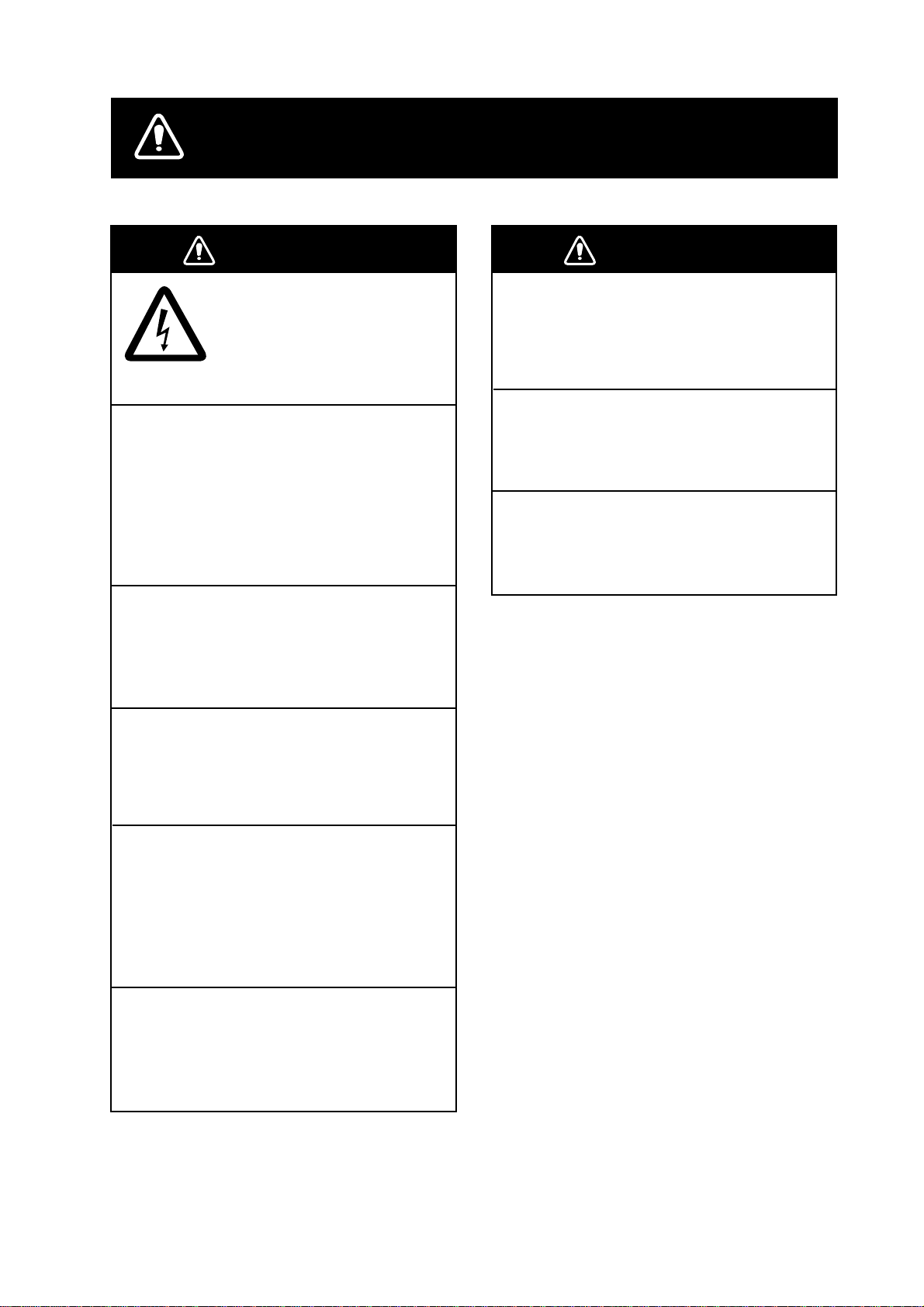
SAFETY INSTRUCTIONS
WARNING
ELECTRICAL SHOCK HAZARD
Do not open the equipment.
Only qualified personnel
should work inside the
equipment.
Immediately turn off the power at the
switchboard if water leaks into the
equipment or something is dropped in
the equipment.
Continued use of the equipment can cause
fire or electrical shock. Contact a FURUNO
agent for service.
Do not disassemble or modify the
equipment.
Fire, electrical shock or serious injury can
result.
WARNING
Keep heater away from equipment.
A heater can melt the equipment's power
cord, which can cause fire or electrical
shock.
Use the proper fuse.
Use of a wrong fuse can damage the
equipment.
Do not operate the equipment with wet
hands.
Electrical shock can result.
Do not place liquid-filled containers on
the top of the equipment.
Fire or electrical shock can result if a liquid
spills into the equipment.
Immediately turn off the power at the
switchboard if the equipment is emitting
smoke or fire.
Continued use of the equipment can cause
fatal damage to the equipment. Contact a
FURUNO agent for service.
Make sure no rain or water splash leaks
into the equipment.
Fire or electrical shock can result if water
leaks in the equipment.
i
Page 4
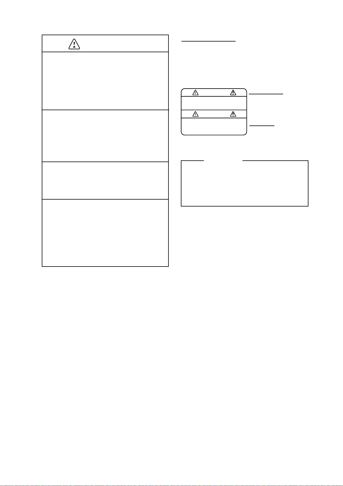
CAUTION
Check the zinc plate (anticorrosion
measure) regularly for corrosion and
replace it when the ship is drydocked.
WARNING LABEL
A warning label is attached to the
transceiver and monitor units. Do not
remove the labels. If a label is missing
or damaged, contact a FURUNO agent or
dealer about replacement.
Corrosion may occur. As a result the
transducer may fall out, allowing water to
leak inside the vessel.
Do not use the equipment for other than
its intended purpose.
Damage to the equipment or bodily
injury may result if the equipment is
misused.
Do not transmit with the transducer out
of water, when drydocked, etc.
The transducer may become damaged.
Turn off the power at the switchboard
immediately whenever you feel the
equipment is abnormal.
Turn off the equipment at the switchboard
if it becomes warm or is making strange
noises. Contact your dealer at your earliest
convenience.
WARNING
To avoid electrical shock, do not
remove cover. No user-serviceable
parts inside.
Transceiver Unit
Name: Warning Label (1)
Type: 86-003-1011-1
Code No.: 100-236-231
Monitor Unit
Name: Warning Label (2)
Type: 03-129-1001-1
Code No.: 100-236-741
TFT LCD
The high quality TFT LCD displays 99.99%
of its pixels. The remaining 0.01% of pixels
may light or dropout, however this is not
an indication of malfuction; it is a
characteristic of the LCD.
ii
Page 5

TABLE OF CONTENTS
FOREWORD...................................................................................................................v
SYSTEM CONFIGURATION..........................................................................................vi
DISPLAY EXAMPLE.....................................................................................................vii
1. OPERATIONAL OVERVIEW.................................................................................. 1-1
1.1 Controls................................................................................................................................ 1-1
1.2 Turning the Power On/Off.................................................................................................... 1-2
1.3 Adjusting LCD Brilliance ...................................................................................................... 1-3
1.4 Choosing a Display..............................................................................................................1-4
1.4.1 Tide vector display .................................................................................................... 1-4
1.4.2 Ship’s speed display ................................................................................................. 1-5
1.4.3 Graph display ............................................................................................................ 1-5
1.4.4 Course plot display ................................................................................................... 1-6
1.4.5 Text display ............................................................................................................... 1-6
1.4.6 Echo level display ..................................................................................................... 1-7
1.5 Setting Measuring Depths ................................................................................................... 1-8
1.6 Choosing Speed Tracking Mode.......................................................................................... 1-9
1.7 Choosing the Range .......................................................................................................... 1-10
2. INTERPRETING THE DISPLAYS.......................................................................... 2-1
2.1 Tide Vector Display .............................................................................................................. 2-1
2.2 Ship’s Speed Display ........................................................................................................... 2-5
2.3 Graph Display ...................................................................................................................... 2-7
2.4 Course Plot Display .............................................................................................................2-9
2.5 Echo Level Display ............................................................................................................ 2-10
2.6 Error Display ...................................................................................................................... 2-11
3. CUSTOMIZING THE SYSTEM............................................................................... 3-1
3.1 Menu Operation ................................................................................................................... 3-1
3.2 Function Keys ...................................................................................................................... 3-3
3.2.1 Programming the function keys ................................................................................ 3-3
3.2.2 Using the function keys............................................................................................. 3-3
3.3 MENU 1 Menu .....................................................................................................................3-4
3.4 MENU 2 Menu .....................................................................................................................3-7
3.4.1 MODE menu ............................................................................................................. 3-7
3.4.2 DISP1 menu.............................................................................................................. 3-8
3.4.3 DISP2 menu............................................................................................................ 3-10
3.5 ALARM Menu..................................................................................................................... 3-12
3.5.1 Alarm types ............................................................................................................. 3-12
3.5.2 Setting/Canceling tide speed, tide direction, tide differential and
ship’s speed alarms ................................................................................................ 3-13
3.5.3 Setting the trip alarm............................................................................................... 3-15
3.5.4 Disabling/enabling the audible alarm...................................................................... 3-16
3.5.5 Disabling an alarm ..................................................................................................3-16
iii
Page 6

v
4. MAINTENANCE & TROUBLESHOOTING............................................................ 4-1
4.1 Routine Maintenance........................................................................................................... 4-1
4.2 Replacing Fuses .................................................................................................................. 4-2
4.3 Troubleshooting ................................................................................................................... 4-3
4.4 Diagnostics ..........................................................................................................................4-4
4.4.1 General test............................................................................................................... 4-4
4.4.2 Panel test ..................................................................................................................4-6
4.4.3 Test pattern ............................................................................................................... 4-7
4.5 Error Messages and Alerts .................................................................................................. 4-8
APPENDIX................................................................................................................AP-1
MENU TREE.............................................................................................................................. AP-1
TIDE MEASUREMENT IN NAV MODE..................................................................................... AP-3
PRINCIPLE OF OPERATION.................................................................................................... AP-6
SPECIFICATIONS.....................................................................................................SP-1
INDEX.........................................................................................................................IN-1
i
Page 7

v
FOREWORD
A Word to the Owner of the CI-68
Congratulations on your choice of the FURUNO CI-68 Doppler Sonar Current Indicator. We
are confident you will see why FURUNO has become synonymous with quality and
reliability.
For over 50 years FURUNO Electric Company has enjoyed an enviable reputation for
innovative and dependable marine electronics equipment. This dedication to excellence is
furthered by our extensive global network of agents and dealers.
Your current indicator is designed and constructed to meet the rigorous demands of the
marine environment. However, no machine can perform its intended function unless
installed, operated and maintained properly. Please carefully read and follow the
recommended procedures for operation and maintenance.
Thank you for considering and purchasing FURUNO equipment.
Features
•
With heading data from a gyrocompass,
satellite compass, etc., the absolute
movements of tide measuring layers is
displayed, in colors.
•
When ground (bottom) reference is not
available acoustically; namely, ship is in
deep water, this equipment provides
absolute movements of measuring layers
by receiving position (or speed) data from
a GPS navigator and heading data from
a gyrocompass or satellite compass.
•
Single-mold transducer plus compact
monitor unit, control unit, transceiver unit
and junction box (option) permit
installation on small vessels.
•
Data is displayed on a bright, non-fading
10.4” TFT LCD. Background color is
selectable from three colors.
•
Commercially available monitor may be
used in lieu of the LCD monitor.
•
Logical keyboard layout and menu
structure for intuitive operation. Function
key provides shortcut menu operation.
•
Triple-beam system for automatic error
compensation against pitching and
rolling.
•
Echo level continuously displayed on the
screen, for monitoring signal conditions
on three sounding beams.
•
Bottom echo can be found using external
depth data. Further, the bottom echo can
be acquired manually by monitoring the
echo level display. This is useful when in
deep seas, air bubbles block reception of
the bottom echo, or a thick layer of
plankton or a large fish school is
mistakenly tracked as the bottom echo.
•
Various alarms: tide, tide differential,
speed, trip, etc. Audible and visual alerts
are released if alarm condition is violated.
•
Six display modes to discern tide
movement from a variety of angles.
•
Graph display shows past current data.
•
Water temperature graph helps locate
current rip. (Temperature sensor
required.)
Page 8

SYSTEM CONFIGURATION
MONITOR UNIT
MU-100C
TRANSCEIVER UNIT
CI-6810
OR
CONTROL UNIT
CI-6888
VGA Monitor
CONTROL UNIT
CI-6888
NMEA1 Output
NMEA1 Input
NMEA2/CIF Output
NMEA2/CIF Input
Current Indicator Data
AUX (NMEA/CIF/Current Indicator Data/
Data for Display)
Heading Sensor
Alert/Alarm
Speed Log (2 lines)
KP Output
KP Input (Two lines)
Power ON/OFF Status (Contact signal)
100/110/115/200/
220/230/240 VAC,
f
1, 50-60Hz
24 VDC
DC-AC INVERTER
TR-2451
JUNCTION BOX
CI-630
TRANSDUCER
CI-620
System c onfiguration
: Standard Supply
: Optional Supply
: Local Supply
vi
Page 9
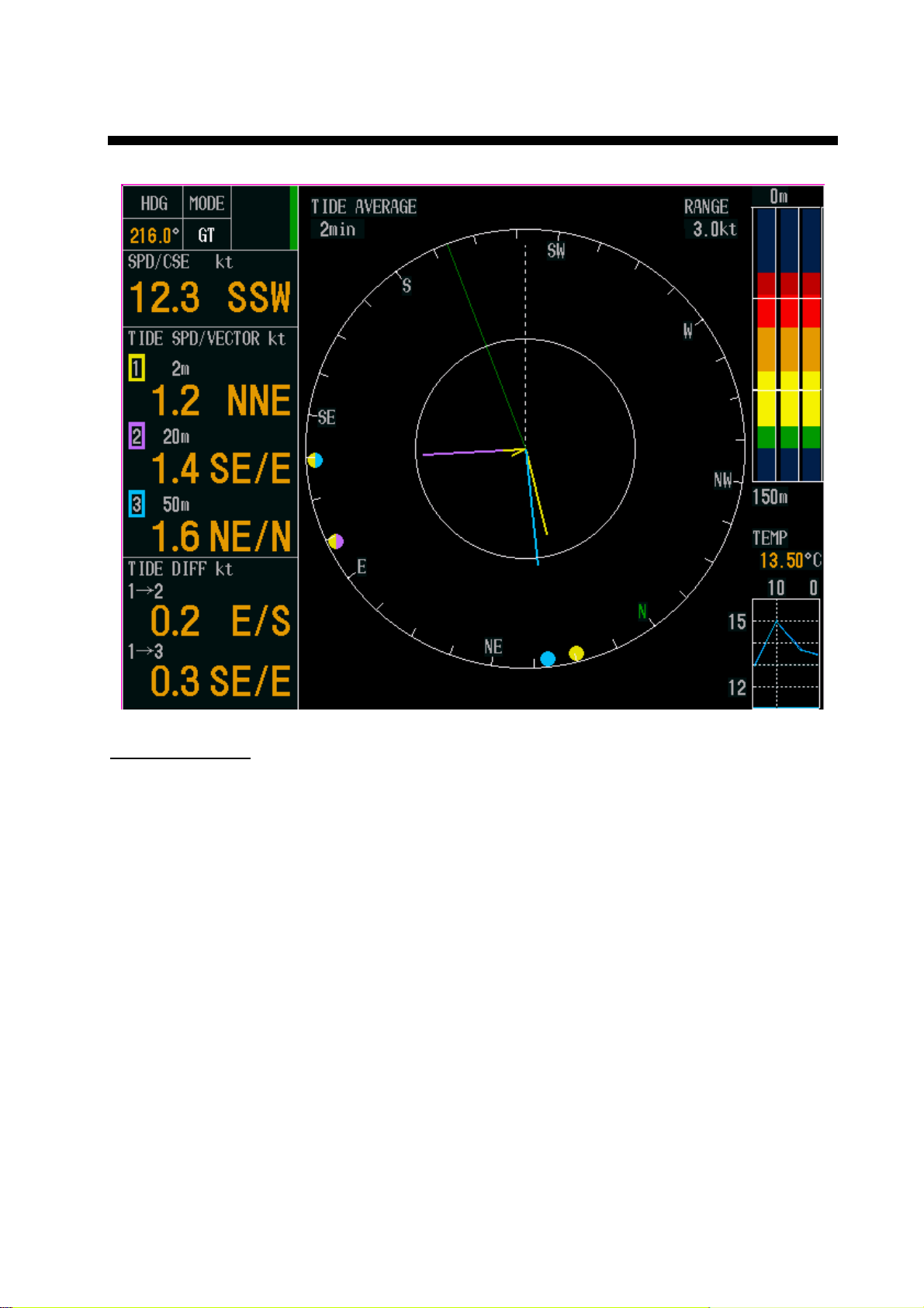
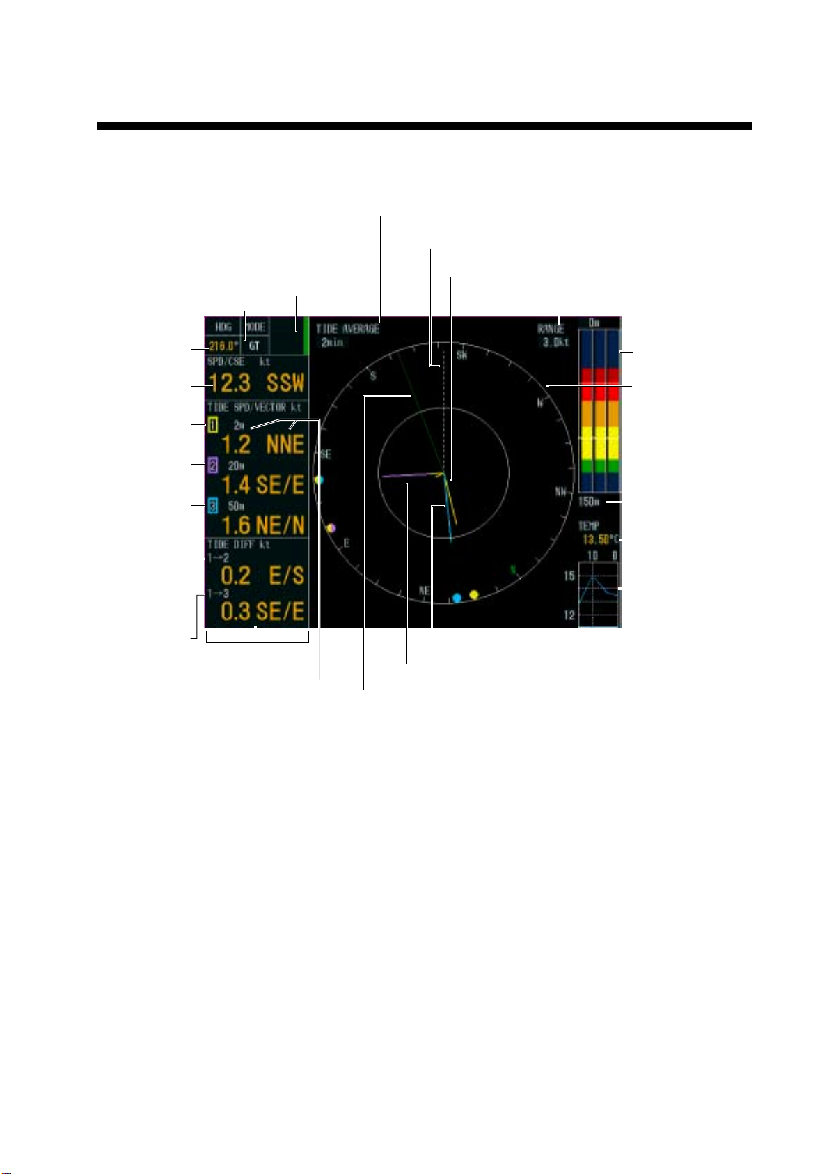
DISPLAY EXAMPLE
Object an d color
•
Tide of layer 1: Yellow
•
Tide of layer 2: Purple
•
Tide of layer 3: Light-blue
•
Own ship speed vector: Green
•
Heading line: White (dashed)
Tide vector display
vii
Page 10

Page 11
1.
OPERATION AL OVERVIEW
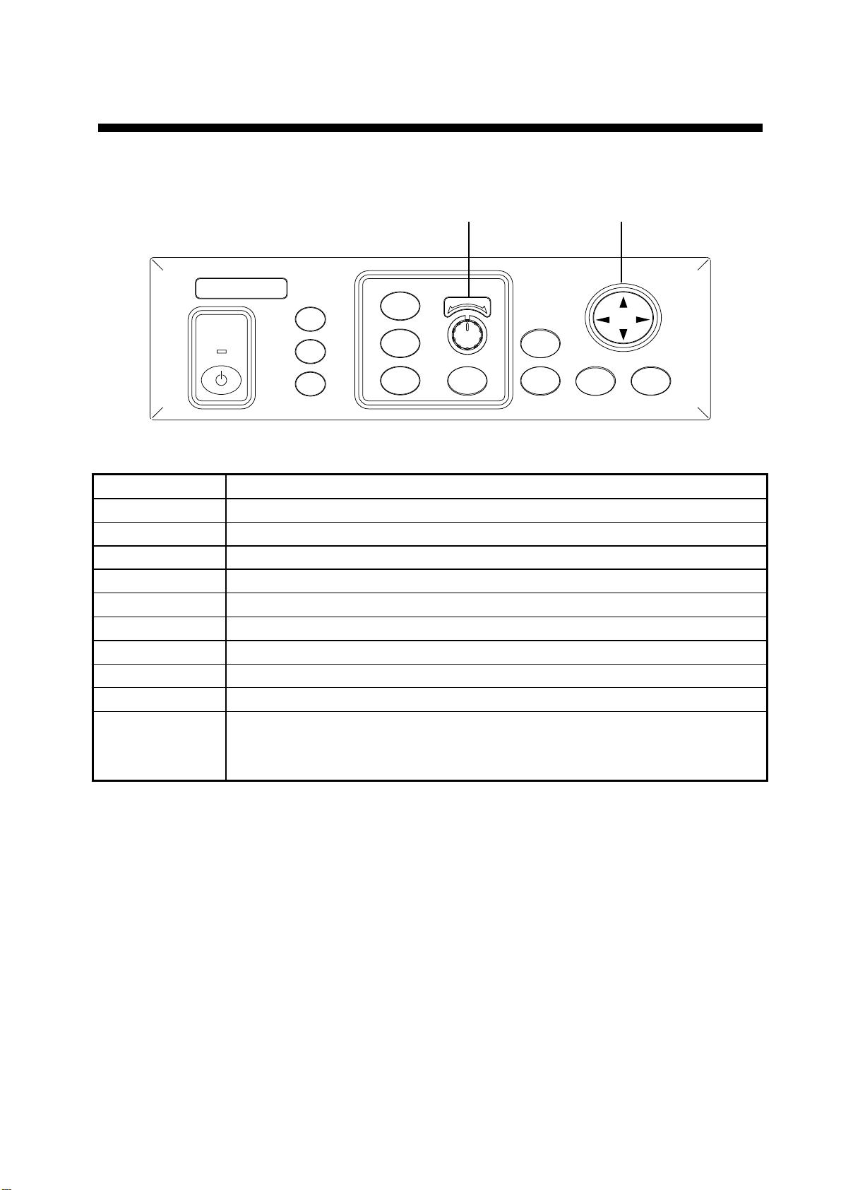
1.1 Controls
CursorPadSetting Knob
FURUNO
CURRENT INDICATOR
LYR1
LYR2
LYR3
POWER
F1
F2
F3
Control uni t
Control Function
POWER Turns power on or off.
F1 – F3 Function keys (menu shortcut keys)
LYR1 – LYR3 Set tide measuring depths for respective layers.
Setting Knob Sets measuring depth and range.
RANGE Sets range. The range which can be set depends on mode.
TRACK MODE Chooses tracking mode among ground, water (or nav) and auto.
DISP MODE Chooses a display mode.
BRILL Adjusts brilliance of LCD.
MENU Opens and closes the menu.
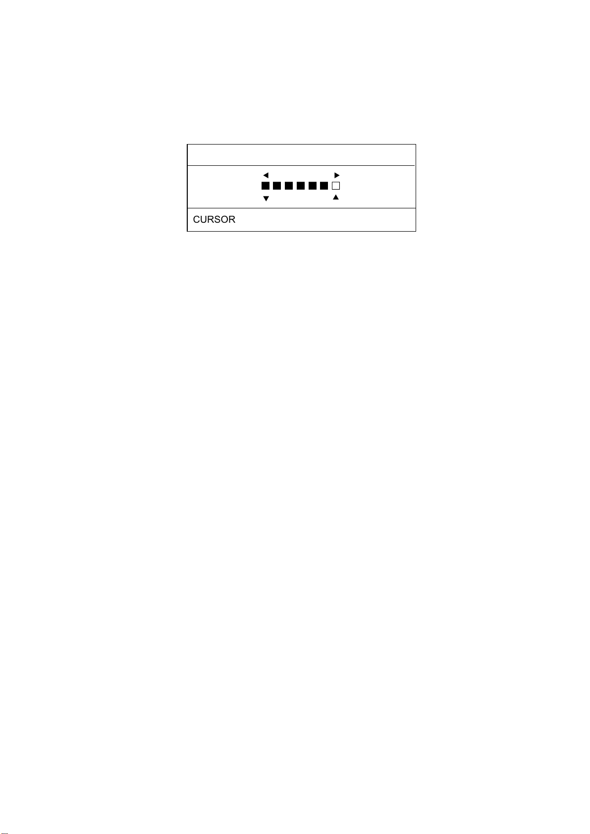
CursorPad • Chooses menu items and options.
• Increases or decreases numerical setting on menus and pop-up windows.
• Silences audible alarm.
- +
RANGE
TRACK
MODE
DISP
MODE
BRILL
MENU
1-1
Page 12

1. OPERATIONAL OVERVIEW
1.2 Turning the Power On/Off
1. Press the [POWER] switch at the left hand side of the control unit to turn the power on. A
beep sounds, the equipment turns on, and the lamp above the switch lights. The
equipment conducts the diagnostic test to check for proper operation between the
transceiver unit and the control unit and displays the results. After the diagnostic test is
completed the last-used display appears.
CI-68
CI-6888
VOL.6651000-XX.XX
MEM. 1 2 3 OK
CI-6810
VOL.6651001-XX.XX
TBL.
MEM. 1 2 3 4 5 6 7 8 OK
ANA.12V;12.03V BV; 110.0V
TRM. +25.02°C
DSW. 00
DSW. - -
00 00 00
00 00 00
XX: Program Version No.
Diagnosti c test
Note: The example screens shown in this manual may not match the screens you see
on your display. The screen you see depends on your system configuration and
equipment settings.
2. To turn the power off, press the [POWER] switch again.
Note: The NAV mode measures tides in deep waters where ground tracking is not available.
To use this function effectively, accurate heading data (from a gyrocompass, satellite
compass) is necessary. For further details, see page AP-3.
1-2
Page 13
1. OPERATIONAL OVERVIEW
1.3 Adjusting LCD Brilliance
You can adjust the brilliance of the FURUNO-supplied monitor as below. To adjust the
brilliance of a commercial monitor, see its owner’s manual.
1. Press the [BRILL] key to open the brilliance adjustment window.
BRILLIANCE
L
H
ggggggc
6
L
H
CURSOR PAD, [BRILL] KEY: CHANGE SETTING
Brillianc e adjustment window
Note: Execute the next step within five seconds after displaying the brilliance
adjustment window. Otherwise the window is erased.
2. Press ► or ▲ to raise the brilliance; ◄ or ▼ to lower it. The brilliance may also be
adjusted by pressing the [BRILL] key. In this case, brilliance is adjusted cyclically:
0→1→…7→6…0→.
Note: You can adjust the backlighting for the control panel with PANEL DIMMER on the
MENU 1 menu.
1-3
Page 14
1. OPERATIONAL OVERVIEW
1.4 Choosing a Display
This current indicator has six main displays: tide vector display, ship’s speed display, course
plot display, text display, echo level display and graph display. You may choose a display by
pressing the [DISP MODE] key.
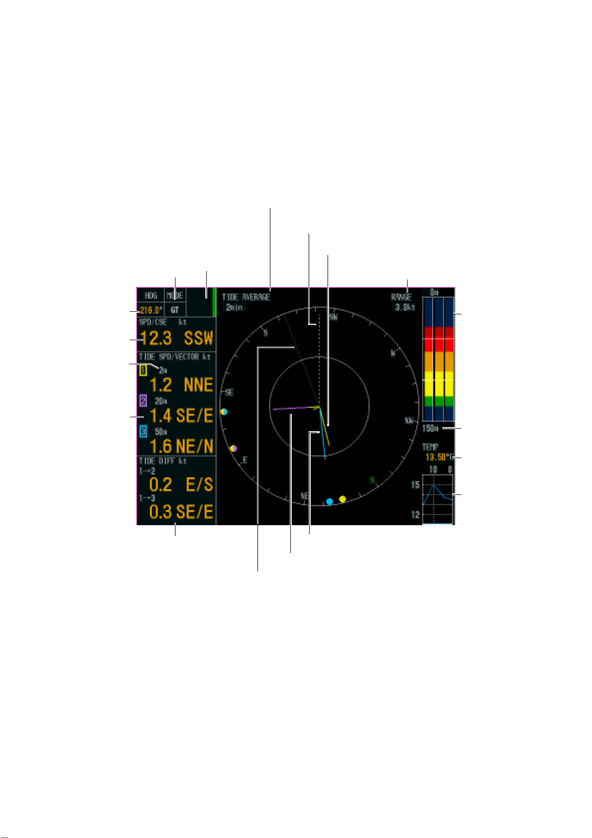
1.4.1 Tide vector displ a y
The tide vector display mainly shows tide speed and direction for three layers with a vector.
Tide Average Setting
Heading Line
Tide of Layer 1 (Yellow)
Tracking Mode
Heading*
Speed, Course*
Depth Setting
Tide Speed
and Direction
(3 layers)
Mode Marker
Tide Differential
Tide of Layer 3 (Light-blue)
Tide of Layer 2 (Purple)
Tide Speed Range
Echo Level
Echo Display
Range
Water
Temperature*
Water Temperature
Graph*
*: Sensor required.
1-4
Own Ship Vector (Green)
Tide vector display
Page 15
1. OPERATIONAL OVERVIEW
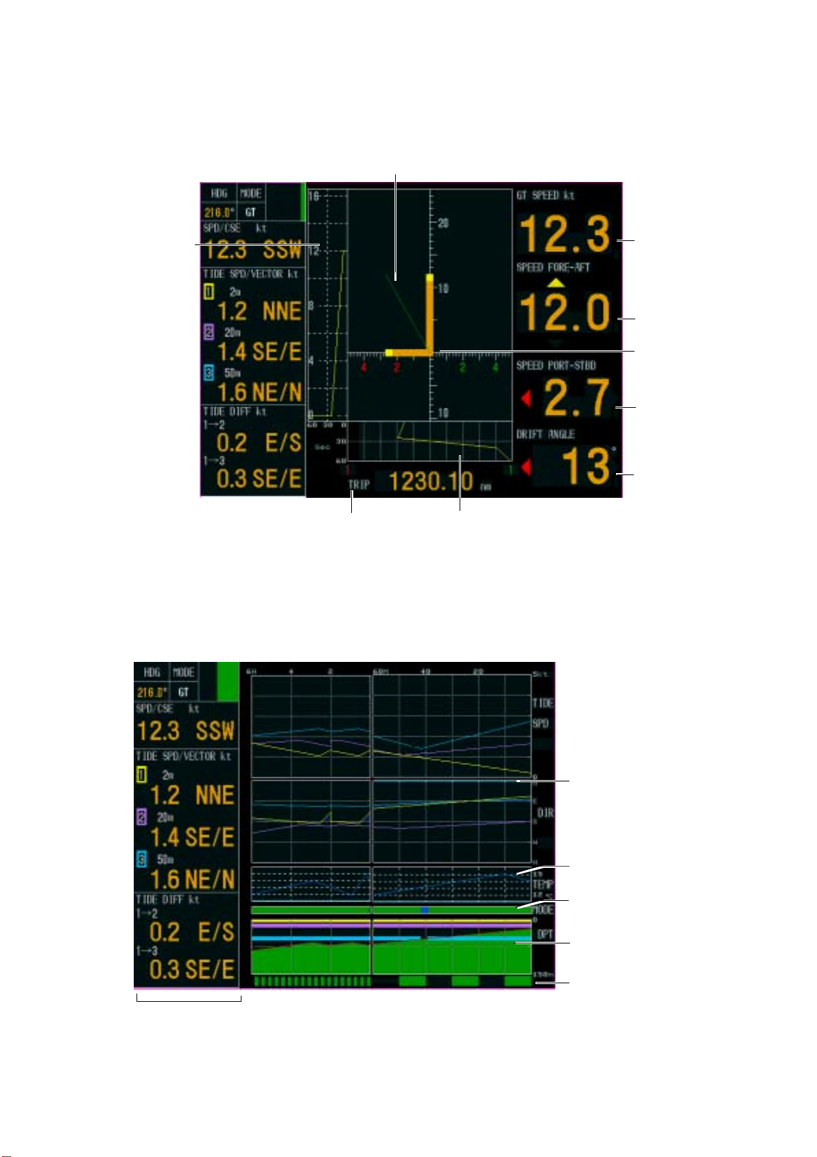
1.4.2 Ship’s speed display
The ship’s speed display shows ship’s fore-aft and port-starboard speeds in analog and
digital form.
Synthesized Speed Vector (Green)
Fore-Aft Speed
History Graph
1.4.3 Graph display
Trip
Distance
Port-Starboard Speed History Graph
Ship’s speed display
Ship Speed
(Synthesized Speed)
Fore-Aft Speed
Own Ship Vector
Port-Starboard
Speed
Drift Angle
The graph display plots water temperature and depth data in graph form.
Tide Graph
(or Tide Diff
or Ship Speed)
Water Temp. Graph*
Mode Marker
Depth Graph
Trip Distance
Text Window
*: Sensor required.
Marker
Graph display
1-5
Page 16
1. OPERATIONAL OVERVIEW
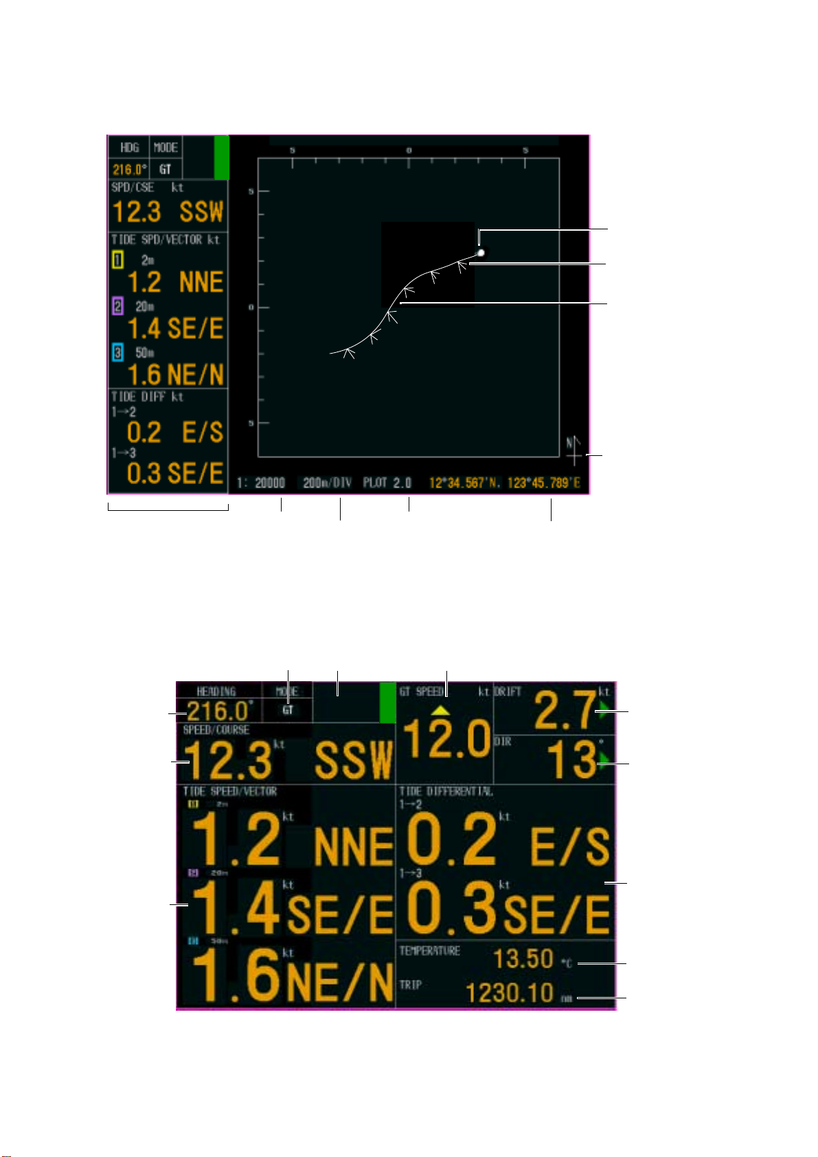
1.4.4 Course pl ot di splay
The course plot display plots ship’s track along with tide vectors.
Own Ship Position
Tide Vector
Ship’s Track
Text Window
Scale
DIV
Tide Display Interval
Course plot display
1.4.5 Text display
The text display provides various nav data in digital format.
Tracking Mode
Heading
Speed
and
Course
Mode Marker
Fore-Aft Speed
Position
North Mark
Port-Starboard
Speed
Drift Angle
Tide Speed
and Direction
(3 layers)
1-6
Text display
*: Sensor required.
Tide Differential
Water Temperature*
Trip Distance
Page 17
1. OPERATIONAL OVERVIEW
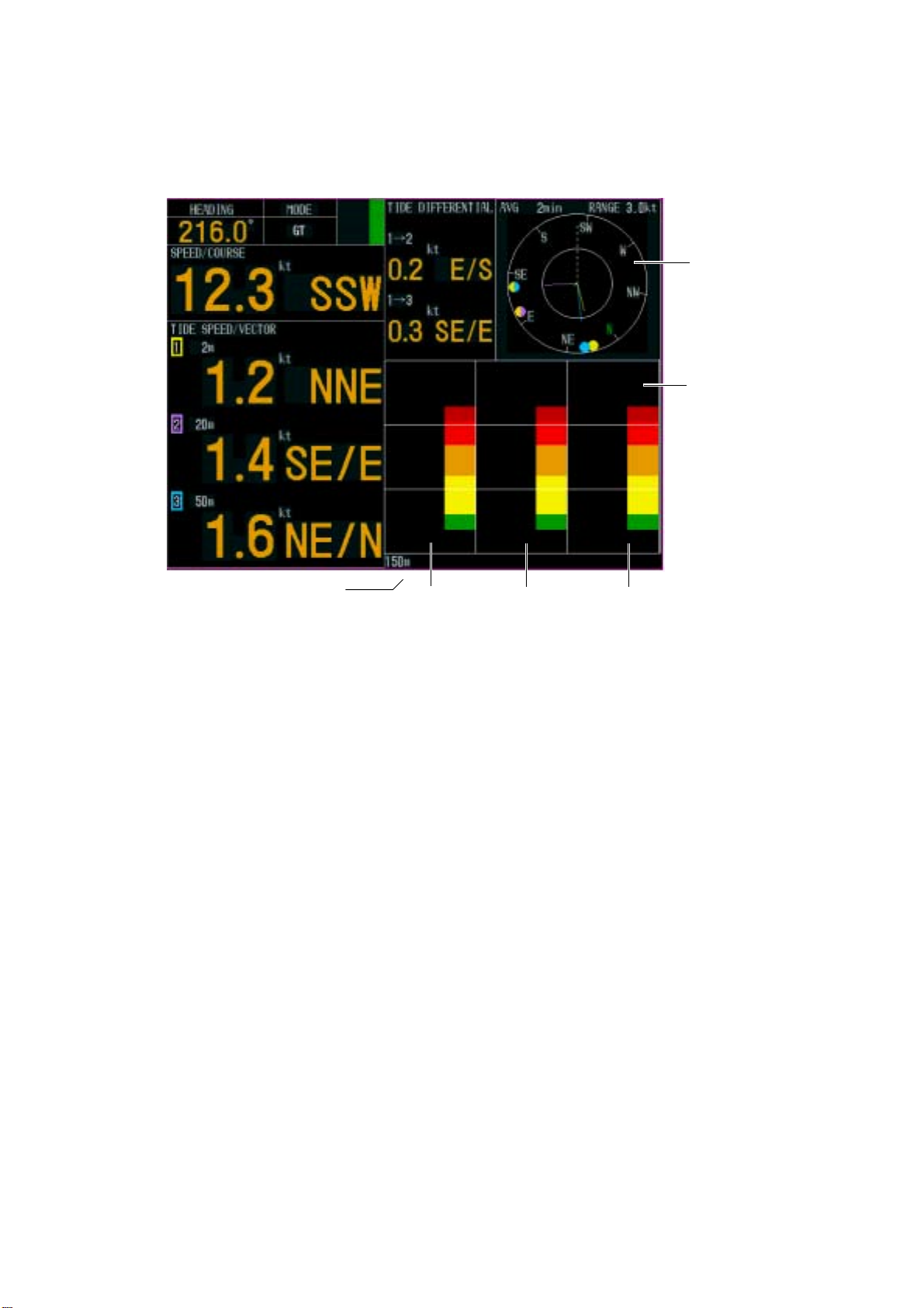
1.4.6 Echo level display
The echo level display shows the strength of the echoes captured by three sounding beams.
Note that ECHO LEVEL in the MODE menu must be set to ON to show the echo level
display.
Tide Vector
Echo Level
Echo Display Range
Beam 3
Beam 2Beam 1
Echo level di s play
1-7
Page 18

1. OPERATIONAL OVERVIEW
1.5 Setting Measuring Depths
Set the depths at which you wish to measure tide speed and direction as below. Note that
layer 3 cannot be set when BTM TIDE TRACK in the MENU 1 menu is set to ON.
1. Press the [LYR1], [LYR2] or [LYR3] key as appropriate to show the depth setting
window.
SETTING DEPTH (LAYER1)
20
m (2-400)
KNOB OR CURSOR PAD: CHANGE SETTING
Depth setting window
2. Within five seconds after completing step 1, operate the Setting Knob or the CursorPad
to set depth of measurement. The setting range is 2-400 (meters).
Setting Knob: Rotate clockwise to raise the range; counterclockwise to lower the range.
CursorPad: Press ► or ▲ to raise the range; ► or ▼ to lower the range.
1-8
Page 19
1. OPERATIONAL OVERVIEW
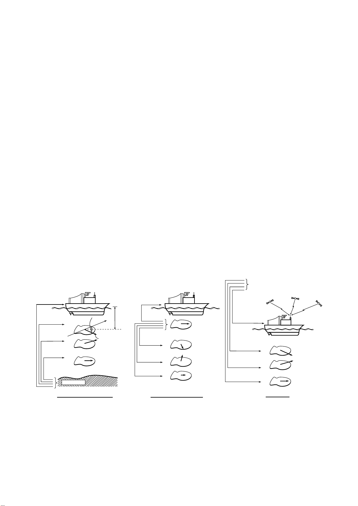
1.6 Choosing Speed Tracking Mode
The tracking mode is available in ground tracking, water tracking, NAV and automatic.
Ground tracking: Absolute ship and tide movements based on ground and current (tide
display (bottom echo must be present).
Water tracking: Ship and tide movements relative to near-surface water and tide
differential between tide layers. (The pulse length in this mode must be
NORMAL and depth greater than 40 m, or LONG pulse length and depth
greater than 70 m.)
Nav: Ship’s movement as measured by a navigation device and tide
movements based on nav speed data.
Auto/external*: Uses ground tracking mode when bottom echo is available and switches
to water tracking mode (or Nav mode) when bottom echo is lost. The
bottom echo is continuously sought, and if re-acquired the ground
tracking mode is restored. *EXT appears in the tracking mode window
(top left corner) when DEPTH MODE in the OTHER menu (sub menu in
the installation menu) is set to EXTERNAL.
To choose the tracking mode, press the [TRACK MODE] key. The tracking mode changes
according to the setting (OFF or ON) of NAV MODE in the MENU 1 menu. The current
tracking mode appears at the top left-hand corner on the screen.
OFF: The tracking mode changes cyclically in the sequence of ground tracking, water
tracking and auto.
ON: The tracking mode changes cyclically in the sequence of ground tracking, nav and
auto.
Ship's movement
based on ground
Tide movement
of layer 1
Tide movement
of layer 2
Tide movement
of layer 3
Bottom
Ground Tracking Mode Water Tracking Mode
Dir
Layer 1
Speed
Layer 2
Layer 3
Measuring
N
depth
Ship's movement
relative to surface
water
Tide movement of
layer 1 relative to
surface water
Tide movement of
layer 2 relative to
surface water
Tide movement of
layer 3 relative to
surface water
Tracki ng modes
Ship's movement
measured by
using satellites
Surface Layer
(Reference layer)
Layer 1
Layer 2
Layer 3
(Based on ground)
Tide movement
of layer 1
Tide movement
of layer 2
Tide movement
of layer 3
Nav Mode
GPS Satellies
Layer 1
Layer 2
Layer 3
1-9
Page 20
1. OPERATIONAL OVERVIEW
1.7 Choosing the Range
You may choose the speed range as follows:
1. Press the [RANGE] key to show the range setting window.
TIDE SPEED RANGE
1.0
kt (0.5-10.0)
KNOB OR CURSOR PAD: CHANGE SETTING
Range setting window ( example: range setting window for tide vect or display)
2. Within five seconds after completing step 1, operate the Setting Knob or the CursorPad
to set the range.
Setting Knob: Rotate clockwise to raise the range; counterclockwise to lower the range.
CursorPad: Press ► or ▲ to raise the range; ► or ▼ to lower the range.
Display and r ange to set
Display Range
Tide vector Tide speed range setting window appears. Set tide/tide differential range
(radius of vector display ring) appropriately.
Ship’s speed The ship’s speed range setting window shown depends on whether SCALE
SYNC in the DISP2 sub menu is set to ON or OFF.
ON: Port-starboard and fore-aft speeds are synchronized. The ship’s speed
range setting window appears. Set speed appropriately.
OFF: The ship’s speed range setting window appears. Set fore-aft speed
appropriately.
Graph The speed range setting window shown depends on the setting of MODE in
the DISP1 sub menu.
TIDE or TIDE DIF: The tide speed range setting window appears. Set tide
speed range (port-starboard of tide speed/tide differential graph)
appropriately.
SPEED: The ship’s speed range setting window appears. Set ship’s speed
range (fore-aft of ship’s speed graph) appropriately.
Course plot The display scale setting window appears. Set display scale as appropriate.
Echo level
Tide speed range setting window appears. Set tide and tide differential range
(radius of vector display ring) appropriately.
1-10
Page 21
2.
INTERPRETING THE DISPLAYS
2.1 Tide Vector Display
Mode Marker
Tracking Mode
Heading*
Speed, Course*
Layer 1: Yellow
Layer 2: Purple
Layer 3: Light-blue
Tide differential
between reference
and deeper of
other two layers
Tide differential
between reference
and shallower of
other two layers
Text Window
Speed and direction
of tide and tide
differential
Tide Average Setting
Heading Line
Tide of Layer 1 (Yellow)
Tide of Layer 3 (Blue)
Tide of Layer 2 (Purple)
Own Ship Vector (Green)
Tide Speed Range
Echo Level
Electronic
Bearing Scale*
Echo Display
Range
Water
Temperature*
Water Temperature
Graph*
*: Sensor required.
Note: Missing or wrong
data is denoted
with " --".
Tide vector display
2-1
Page 22
2. INTERPRETING THE DISPLAYS
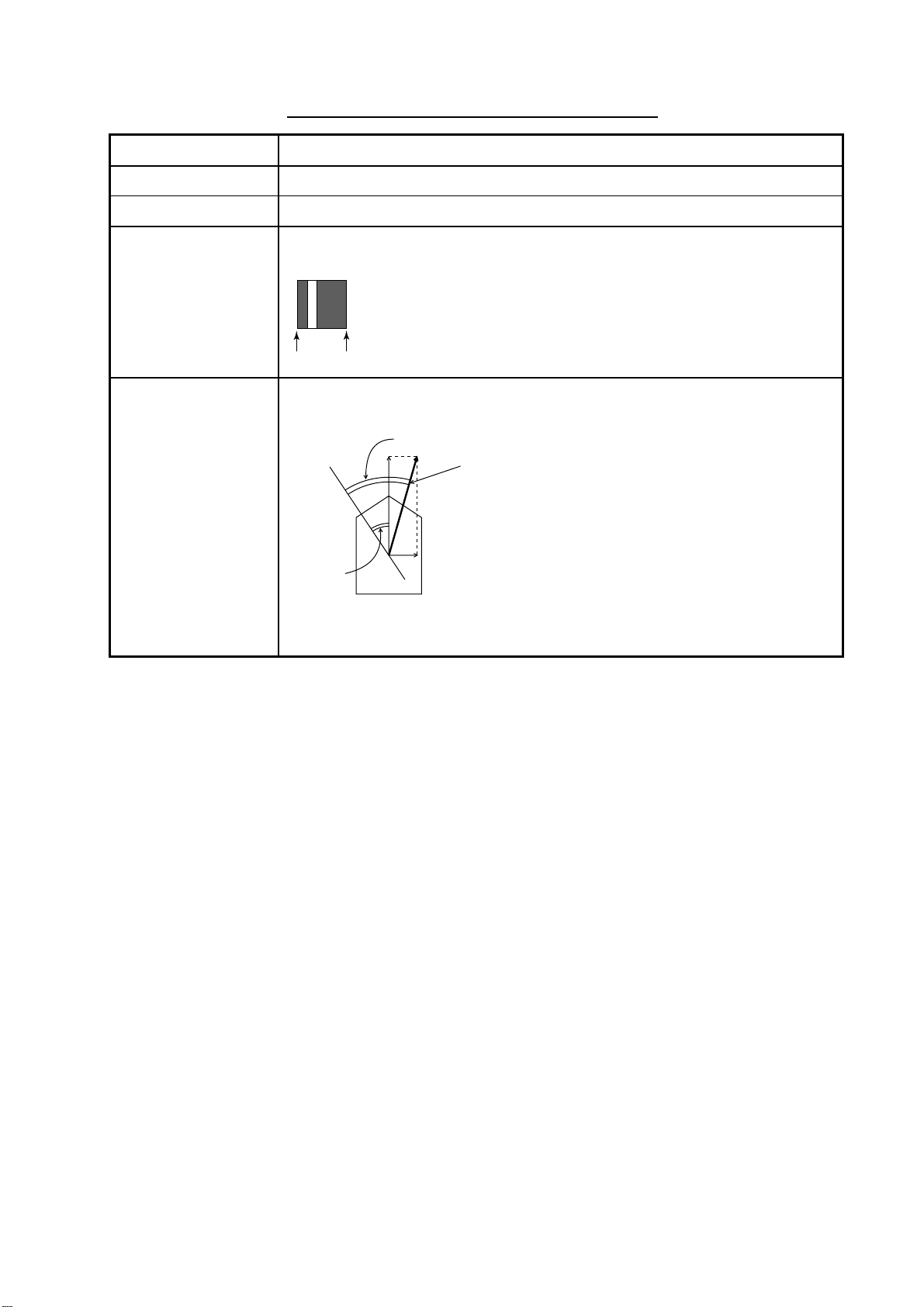
Description of indic ations on tide v ec tor display
Item Description
Heading Ship’s heading fed from a heading sensor.
Mode Shows current tracking mode, as selected with the [TRACK MODE] key.
Mode marker
Shows tracking mode and echo availability for last three minutes, scrolling
from right to left. The color represents tracking mode as shown below.
Green: Ground tracking mode
Blue: Water tracking mode, nav mode
Background: Speed error
3 min
Current mode
Speed/course Speed made good and true course are shown. The displayable range is 0.0
to 40.0 kts for speed and 0° to 359° for course.
True course
N
Heading
(fed from
heading
sensor)
Speed made good
(ground tracking speed,
water tracking speed or
nav speed)
2-2
Page 23

2. INTERPRETING THE DISPLAYS
Item Description
Tide speed and
direction
Tide speed and direction is shown for three layers (measuring depths). The
displayable range is 0.0 to 9.9 kts for speed and 0° to 359° for course. Data
shown depends on the measuring mode as follows:
Ground tracking mode: Speed and direction values of measuring layers
represent movement of layer relative to ground.
Water tracking mode: Speed and direction values of measuring layers
represent movement of layer relative to near-surface water.
Nav mode: Speed and direction values represent movement of measuring
layers relative to pseudo ground.
Ship's movement
based on ground
Tide movement
of layer 1
Tide movement
of layer 2
Tide movement
of layer 3
Bottom
Dir
Layer 1
Speed
Layer 2
Layer 3
Measuring
N
depth
Ship's movement
relative to surface
water.
Tide movement of
layer 1 relative to
surface water.
Tide movement of
layer 2 relative to
surface water.
Tide movement of
layer 3 relative to
surface water.
Surface Layer
(Reference layer)
Layer 1
Layer 2
Layer 3
Ground Tracking Mode Water Tracking Mode
Ship's movement
GPS Satellies
measured by
using satellites
(Based on ground)
Tide movement
of layer 1
Layer 1
Tide movement
of layer 2
Layer 2
Tide movement
of layer 3
Nav Mode
Layer 3
Tide differential Tide speed and direction differential are shown between reference layer and
shallower of the other two layers. The displayable range is 0.0 to 9.9 kts for
speed and 0° to 359° for course. The reference layer may be selected with
REF TIDE DIFF in the MENU 1 menu. For example, if the reference layer is
layer 3, the tide differential between it and layer 1 and layer 2 will be
displayed.
Water temperature Water temperature is shown if a water temperature sensor is connected to the
current indicator. The display range is -5 to 99 (°C).
Water temperature
graph
Water temperature over the latest 15 minutes is displayed with a blue line, the
data scrolling from right to left. The range of the temperature scale is 5°C and
the range of the time scale is 15 minutes.
2-3
Page 24

2. INTERPRETING THE DISPLAYS
Item Description
Heading line
Tide/tide
differential vector
The heading line is a dashed line which shows ship’s heading. It extends from
ship’s position (center of vector display) to the edge of the vector display. The
line can be turned on or off with HEADING LINE in the DISP1 menu.
Tide vectors may be turned on or off with LAYER 1, LAYER 2 and LAYER 3 in
the DISP1 menu. The tide differential may be also be turned on or off with
TIDE DIFF in the DISP1 menu. Note that if vectors overlap, the vector of the
highest layer is shown.
Tide Vectors
(2)
NW
(1)
N
NE
(3)
(4)
W
E
Tide
Differential
Vectors
(5)
SW
SE
S
Heading Line
Yellow
Purple
Light-blue
Ship’s speed
vector
Electronic bearing
scale
(1)
(2)
(3)
(4)
(5)
Layer 1
Layer 2
Layer 3
. . . .
2®1
. . . .
®
3
2
. . . .
. . . .
. . . .
Yellow Purple Yellow
Purple
Purple Light-bluePurple Light-blue
Yellow
Purple
Light-blue
Reference
Layer
(Left half)
Purple
Yellow
Purple
Light-blue
Measuring Layer
(Right half)
The ship’s speed vector may be shown on the vector display. This vector can
be turned on or off with SHIP SPD VCTR in the DISP1 menu.
The electronic bearing scale shows bearing. If a heading sensor is connected
the scale rotates with ship’s movement.
Tide speed range Tide speed range, as selected with TIDE RANGE in the DISP1 menu,
appears at the top right-hand side on the screen.
Tide average
The value set with TIDE AVERAGE in the MENU 1 menu is shown.
setting
Echo level The echo level display shows echo level for the three sounding beams in
colors or graph depending on the setting of DISP MODE in the DISP2 menu.
You can turn the display on or off with ECHO LEVEL in the DISP2 menu.
Echo display range The value set with ECHO RANGE in the MENU 1 menu is shown.
2-4
Page 25

2.2 Ship’s Speed Display
2. INTERPRETING THE DISPLAYS
Fore-Aft Speed
History Graph
Synthesized Speed Vector (Green)
Trip Distance
Ship Speed
(Synthesized Speed)
Fore-Aft Speed
Own Ship Vector
Port-Starboard
Speed
Drift Angle
Port-Starboard Speed History Graph
Ship’s speed display
Description of ship’s speed display indications
Item Description
Ship’s speed* (In
GT, WT) or
Water tracking
speed
(In Nav mode)
Fore-aft speed* Speed in the fore-aft direction. The speed setting range is 0.0 to 40.0 (kt).
Port-starboard
speed*
Port-starboard and fore-aft speeds are synchronized when SCALE SYNC in
the DISP2 menu is set to ON. The available speed setting range is 0.0 to 30.0
(kt).
*: Speed measured depends on setting of SHIP SPD MODE in the DISP1
menu.
Ground tracking mode Water tracking mode
Ref. layer selected Ship’s speed Ship’s speed
Water tracking layer
selected
Ground tracking speed Water tracking speed
Fore speed is denoted with a yellow “▲ ” above the speed readout and aft
speed with a yellow “▼” below the speed readout.
Speed in the port-starboard direction. The speed setting range is 0.0 to 40.0
(kt). Port speed is denoted with a red “◄” to the left of the speed readout and
starboard speed with a green “►” to the right of the speed readout.
Drift angle* The angle measured in degrees between ship’s heading and the actual
movement. When drift angle is to port, a red “◄” appears and when it is to
starboard a green “►” appears. In the NAV mode, drift in water tracking speed
is shown.
Trip Shows trip distance. The distance is referenced to fore or fore/aft depending
on the setting of LOG PULSE OUT in the I/O menu.
2-5
Page 26

2. INTERPRETING THE DISPLAYS
Description of ship’s speed display indicati ons ( c on’t from previous page)
Item Description
Own ship vector*
Fore-aft speed history graph This graph shows fore-aft speed history over time, which is useful
Port-starboard history graph This graph shows port-starboard speed history over time, which is
The own ship vector shows port-starboard speed on the x-axis and
fore-aft speed on the y-axis. The “synthesized speed vector”
(green) appears when SCALE SYNC in the DISP2 menu is set to
ON.
in trawling. HISTORY in the DISP2 menu sets the maximum range
for the graph, and you can shift the range with HISTORY SHIFT in
the DISP2 menu. The latest 60 seconds of fore-aft speed is shown,
scrolling from right to left across the screen.
useful in trawling. DRIFT HISTORY in the DISP2 menu sets the
maximum range for the graph. The latest 60 seconds of
port-starboard speed is shown, scrolling from top to bottom on the
screen.
*: Speed used for calculation depends on setting of SHIP SPD MODE in the DISP1 menu.
GT/WT: Speed is calculated according to tracking mode, ground speed for ground
tracking mode and water speed for water tracking mode.
WT: Speed is calculated using water tracking speed regardless of speed tracking
mode in use.
2-6
Page 27

2.3 Graph Display
2. INTERPRETING THE DISPLAYS
Text Window
0-6 hours
of latest data
Depth of
each layer
0-60 minutes
of latest data
*: Sensor required.
Note: When overlapping occurs,
layer having highest number
has priority.
Max. Range of
Tide Speed
(or Course)
Tide Graph
(or Tide Diff
or Ship Speed)
Water Temp. Graph*
Mode Marker
Depth Graph
Trip Distance
Marker
Graph display
Description of graph display indicat ions
Item Description
Text window The text window may be turned on or off with TEXT WINDOW in
the DISP1 menu. When the text window is turned off, 12 hours of
graph data are shown.
Tide (or tide differential,
speed) graph
You may choose the type of graph to display with MODE in the
DISP1 menu.
The maximum tide speed (or ship’s speed) range may be chosen
with TIDE RANGE in the DISP1 menu.
Tide direction (or course) may be chosen with TIDE GRAPH in the
DISP1 menu.
For the tide graph, graph lines are displayed in colors: Layer 1,
Yellow; Layer 2, Purple, and Layer 3, Light-blue.
For the tide differential graph, the tide differential between layers 1
and 2 is shown in purple and that between layers 1 and 3 in
light-blue.
2-7
Page 28

2. INTERPRETING THE DISPLAYS
Description of graph display indicat ions (con’ t from previous p age)
Item Description
Water temperature graph The water temperature graph may be turned on or off with TEMP
GRAPH in the DISP1 menu.
Mode marker The mode marker shows by color which tracking mode is in use.
Green: Ground tracking mode
Blue: Water tracking mode, nav mode
Background:
Depth graph The depth graph displays depth data in graph form. If, in the water
tracking mode, the depth is greater than the depth range no depth
data is displayed. To graph depth from an external source, set DEPTH
SOURCE in the OTHER menu (sub menu in the installation menu) to
EXTERNAL.
Ship’s speed error
Trip distance marker
The trip distance marker shows trip distance in one-mile increments,
in green and background color alternately as shown below.
1 mile
GreenBackground
color
2-8
Page 29

2.4 Course Plot Display
2. INTERPRETING THE DISPLAYS
Own Ship Position
Tide Vector
Ship’s Track
North Mark
*
: Sensor required.
Text Window
Scale
DIV
Tide Display Interval
Position*
Course plot display
Description of course plot display indications
Item Description
Text window The text window can be turned on or off with TEXT WINDOW in the
DISP2 menu. With the text window turned off, the amount of track
displayed is greater.
Ship’s track Ship’s track is drawn with a white solid line. Ship’s track starts
extending from the screen center and when own ship position
reaches the edge of the screen it is brought back to the screen
center. You may turn the ship’s track line on or off with SHIP
TRACK in the DISP2 menu.
Tide vector
The length of the tide vectors may be chosen with VECTOR
LENGTH in the DISP2 menu. Vectors may be turned on or off with
LAYER 1 – LAYER 3 in the DISP1 menu.
North mark The north mark points upward on the course plot display.
Scale You may choose the scale with SCALE in the DISP2 menu.
DIV Shows range per scale division.
Tide display interval You may choose the tide display interval with INTERVAL in the
DISP2 menu. In the illustration above the interval is “2”.
Position Position is shown in latitude and longitude.
2-9
Page 30

2. INTERPRETING THE DISPLAYS
2.5 Echo Level Display
Tide Vector
Echo Level
Echo Display Range
Item Description
Echo level
Echo display range
Beam 3
Beam 2Beam 1
Echo level di s play
Description of echo level display indications
Echo status of beam 1 (fore), beam 2 (starboard) and beam 3 (port)
is displayed in eight colors.
The echo display range can be set with ECHO RANGE in the
MENU 1 menu.
2-10
Page 31

2. INTERPRETING THE DISPLAYS
2.6 Error Display
An error display is generated whenever display data or measured data is abnormal. When
this occurs the corresponding data will be unreliable.
Speed and course (fore-aft, port-starboard, drift angle)
(1) No data input from
transceiver unit
SPD/CSE kt
12.3 333
(2) Ship’s speed error
Tide vector, speed, graph and
course plot displays
SPEED FORE-AFT
12.0
SPEED PORT-STBD
(2) Ship’s speed
2.7
DRIFT ANGLE
error
(1) No data input from
transceiver unit
SPD/CSE
kt
12.3 333
(2) Ship’s speed error
Text and echo level displays
GT SPEED kt
DRIFT kt
2.7
12.0
DIR
13
(2) Ship’s speed error
°
13
Ship’s speed display Text display
Speed and cour s e er ror displays
(1) No data is being input from the transceiver unit to the display unit. If this occurs, contact
a FURUNO agent or dealer.
(2) This display appears when the ground tracking echo for ground tracking, reference layer
for water tracking or GPS data from the GPS navigator is abnormal. In this case data is
not reliable.
2-1 1
Page 32

2. INTERPRETING THE DISPLAYS
Tide fo r t hree layers/ti de differential
(4) Depth setting error
TIDE SPD/VECTOR kt
1
2m
2.3 140
(3) Echo from measuring layer
is abnormal
Tide vector, speed, graph and
course plot displays
TIDE DIFF kt
1®2
2.3 140
3) Echo from measuring layer
is abnormal
Tide vector, speed, graph and
course plot displays
(4) Depth setting error
TIDE SPD/VECTOR
1
2m
kt
2.3 140
(3) Echo from measuring layer
is abnormal
Text and echo level displays
TIDE DIFF
1®2
kt
2.3 140
3) Echo from measuring layer
is abnormal
Text and echo level displays
Tide and tide diff er ential error dis play s
(3) Displayed when echo for a measuring layer is not present. The readout for the offending
measuring layer is not reliable.
(4) Displayed when the depth setting for a measuring layer is improper. The readout for the
offending measuring layer is not reliable.
Improper depth setting conditions
•
Depth in ground tracking mode is less than 10 m.
•
Depth setting is more than 75% of actual depth.
•
Echo cannot be obtained because of air bubbles, etc.
•
Echo for set depth cannot be found because depth has become deeper than set
depth.
2-12
Page 33

3.
Less-often used functions are stored in the menu. There are four main menus, MENU 1,
MENU 2, ALARM and INSTALLATION. The MENU 2 and INSTALLATION menus have
three sub menus each.
CUSTOMIZING THE SYSTEM
3.1 Menu Operation
1. Press the [MENU] key to open the menu. The last-used menu appears.
MAIN menu
title
MENU 1 MENU 2 ALARM INSTALLATION
SUB menu title
MODE DISP1 DISP2
TIDE VECTOR : OFF ON
SHIP SPEED : OFF ON
GRAPH : OFF ON
COURSE PLOT : OFF ON
TEXT : OFF ON
ECHO LEVEL : OFF ON
BACKGROUND CLR : BLACK WHITE BLUE
Help
2. Press ▲ to place the cursor on the main menu title field.
MENU ON DISPLAY SETTINGS.
[p/q]:SELECT, [t/u]: CHANGE, [MENU]: EXIT
MODE menu
3-1
Page 34

3. CUSTOMIZING THE SYSTEM
3. Press ◄ or ► to choose the main menu desired among MENU 1, MENU 2, ALARM and
INSTALLATION menus. Then, the menu changes according to your selection. For the
MENU 2 and INSTALLATION menus the sub menu title appears. To choose a sub menu,
press ▼ to choose the sub menu title field and then press ◄ or ► to choose the sub
menu desired.
Note: The INSTALLATION menu is locked to prevent unintentional adjustment of its
settings. When you move the cursor from ALARM to INSTALLATION, the
following message appears. To open the INSTALLATION menu, press any
function key.
PRESS ANY FUNC KEY TO OPEN INSTALLATION MENU.
PRESS [MENU] KEY TO OPEN ALARM MENU.
4. Press ▲ or ▼ to choose menu item desired. Selected item is displayed in reverse video
and menu help appears in the box at the bottom of the menu.
5. Press ◄ or ► to choose menu option or change numerical value. To change numerical
value, press ► to raise the value; ◄ to lower the value.
6. Press the [MENU] key to close the menu.
3-2
Page 35

3. CUSTOMIZING THE SYSTEM
3.2 Function Keys
3.2.1 Programmi ng th e fu nc tio n keys
The function keys ([F1]-[F3]) provide menu shortcut operation. You may program the keys
as follows:
1. Press the [MENU] key to display the main menu.
2. Choose menu desired.
Note: The ALARM and INSTALLATION menus cannot be used.
3. Choose menu item desired.
Note: RESET TRIP LOG, TEST and BOTTOM SEARCH in the MENU 1 cannot be
used.
4. Press and hold down a function key until you hear three beeps and the message
“PROGRAMMED SELECTED ITEM TO [F*] KEY” is displayed (about five seconds). (*
Function key number pressed.)
5. Press the [MENU] key to close the menu.
3.2.2 Using the functio n keys
The function keys provide shortcut menu operation, and they are not programmed at the
factory. If a function key contains no program when pressed, the message “NO FUNCTION
ASSIGNED TO [F*] KEY.” appears on the display for about five seconds. (* function key
pressed.)
1. Press any function key. An appropriate setting window appears on the display.
2. Within five seconds after completing step 1, operate the CursorPad to change setting as
below.
Change numeric data: ► or ▲ to raise the setting; ◄ or ▼ to lower it.
Choose option: ► or ▲ to scroll rightward; ◄ or ▼ to scroll leftward.
3-3
Page 36

3. CUSTOMIZING THE SYSTEM
3.3 MENU 1 Menu
This menu mainly provides items for adjustment of tide parameters.
MENU 1 MENU 2 ALARM INSTALLATION
SHIP SPEED AVG : 15 sec 30 sec 60 sec 90 sec
TIDE AVERAGE : 2 min
REF TIDE DIFF : LAYER 1 LAYER 2 LAYER 3
BEARING MODE : 32 CMPS 360 TRUE
NAV MODE : OFF ON
BOTTOM SEARCH: NO YES
BTM TIDE TRACK : OFF ON
ALM/KEY BEEP : OFF ON
WT SPD DEPTH : 2 m (2-400m)
RESET TRIP LOG : NO YES
TEST : NO GENERAL PANEL PATTERN
ECHO RANGE : 150 m
TVG : OFF ON
GAIN : 5 (1-40)
PANEL DIMMER : 5 (0-7)
MENU ON INITIAL SETTINGS.
[p/q]:SELECT, [t/u]: CHANGE, [MENU]: EXIT
MENU 1 m enu
SHIP SPEED AVG
Choose the averaging time for the ship’s speed display. The choices are 15, 30, 60 and 90
seconds.
TIDE AVERAGE
Choose the averaging time for the tide display. If tide speed appears to be too slow, choose
a higher setting. The choices are 15 s, and 1, 2, 3, 5, 10 and 20 minutes.
REF TIDE DIFF
Choose the reference layer for tide differential measurements, among layer 1, layer 2 and
layer 3.
BEARING M ODE
You may show bearing in 32 compass points or 360 degrees.
NAV MODE
NAV MODE enables or disables the NAV mode. Choose ON to use NAV mode instead of
the water tracking mode. For further details, see paragraph 1.6.
3-4
Page 37

3. CUSTOMZING THE SYSTEM
BOTT OM SEARCH
BOTTOM SEARCH enables reacquisition of temporarily lost ground echo, in the water
tracking mode. When the bottom echo is lost for a short while due to air bubbles, or the
equipment tends to track on false bottom, acquire the bottom echo manually as follows:
1. Set BOTTOM SEARCH to YES and close the menu. The rectangle cursor appears on
the display.
2. Press any function key. The tide vector display appears along with the echo level
display.
3. Use ▲ or ▼ to set the cursor on the bottom echo.
Bottom Echo
125
Depth
Cursor
How to acq uire bottom echo
4. Press the [MENU] key to finish and close the menu.
BTM TIDE TRACK
Choose how to track bottom tide, in the ground tracking mode.
ON: Measuring depth of layer 3 changes automatically with the bottom depth to track on
near-bottom tide. In this case the layer 3 indications shows “BTTM” instead of the tide
measurement depth.
OFF: Normal selection of measuring depth for layer 3.
ALM/KEY BEEP
A key beeps to confirm correct key input, input error or error message. You may turn this
beep on or off as desired. The beep sounds when an alarm setting is violated regardless of
whether this item is turned on or off.
WT SPD DEPTH
Set the reference depth at which to measure ship’s speed in the water tracking mode. Set
the depth for which you want to know the water tracking speed in reference to a specific
depth. The setting range is 2-400 (m).
RESET TRIP LOG
Set the trip distance to zero (0). Choose YES and then you are prompted “ PRESS ANY
FUNCTION KEY TO EXECUTE.” Press any function key to reset the trip log to zero.
TEST
Choose the diagnostic test to execute: General (program no. display, memory check, etc.),
panel or pattern. For further details, see paragraph 4.4.
3-5
Page 38

3. CUSTOMIZING THE SYSTEM
ECHO RANGE
Choose the maximum depth to display echoes, from among 50, 100, 150, 200, 250, 300,
350, 400, 450, 500 (m).
TVG
Turn echo TVG on or off.
GAIN
Adjust echo level display color. The higher the digit the nearer to the strongest color
(reddish brown). “GAIN” does not adjust the gain of the received signal; speed and tide
values are not affected by this adjustment. The setting range is 1-40.
PANEL DIMMER
Adjust the backlighting for the control panel, from 0-7.
3-6
Page 39

3. CUSTOMZING THE SYSTEM
3.4 MENU 2 Menu
3.4.1 MODE menu
This menu mainly turns displays on or off. All displays cannot be turned off; at least one
must be turned on. Any display turned off on the MODE menu is removed from selection
with the [DISP MODE] key.
MENU 1 MENU 2 ALARM INSTALLATION
MODE DISP1 DISP2
TIDE VECTOR : OFF ON
SHIP SPEED : OFF ON
GRAPH : OFF ON
COURSE PLOT : OFF ON
TEXT : OFF ON
ECHO LEVEL : OFF ON
BACKGROUND CLR : BLACK WHITE BLUE
MENU ON DISPLAY SETTINGS.
[p/q]:SELECT, [t/u]: CHANGE, [MENU]: EXIT
DISP menu
TIDE VECTOR
Enable or disable the tide vector display.
SHIP SPEED
Enable or disable the ship’s speed display.
GRAPH
Enable or disable the tide graph display.
COURSE PLO T
Enable or disable the course plot display.
TEXT
Enable or disable the text display.
3-7
Page 40

3. CUSTOMIZING THE SYSTEM
ECHO LEVEL
Enable or disable the echo level display.
BACKGROUND CLR
Choose the background color from among black, white and blue.
3.4.2 DISP1 menu
MENU 1 MENU 2 ALARM INSTALLATION
MODE DISP1 DISP2
COMMON SETTINGS
TIDE RANGE : 3.0kt
SHIP SPD VCTR : OFF ON
HEADING LINE : OFF ON
TIDE VECTOR
LAYER 1 : OFF ON
LAYER 2 : OFF ON
LAYER 3 : OFF ON
TIDE DIFF : OFF ON
DISPLAY MODE : HEAD UP NORTH UP
SHIP SPD MODE : GT/WT WT
GRAPH
MODE : TIDE TIDE DIF SHIP SPD
Graph display
settings
TIDE GRAPH : NORTH SOUTH
TEMP GRAPH : OFF ON
TEXT WINDOW : OFF ON
MENU ON DISPLAY SETTINGS.
[p/q]:SELECT, [t/u]: CHANGE, [MENU]: EXIT
DISP1 menu
TIDE RANGE
Set the tide range for the tide vector display, graph display and echo level display. The
choices are 0.5, 1.0, 2.0, 3.0, 5.0 and 10.0 (kts).
SHIP SPD VCTR
Turn the ship’s speed vector on or off on the tide vector display and echo level display.
HEADING LINE
Turn the heading line on or off on the tide vector display and echo level display.
LAYER 1, LAYER 2, LAYER 3, TIDE DIFF
Turn the tide vector on or off for the respective item on the tide vector display and echo
level display.
3-8
Page 41

3. CUSTOMZING THE SYSTEM
DISPLAY MODE
Set display orientation for head-up or north-up. Heading device required for North-up.
Ship’s bow is at the
top of the screen.
HEADING LINE
W
SW
S
SE
E
NW
NE
NW
N
W
SW
Head-up North-up
North is at the
top of the screen.
N
NE
E
SE
S
Head-up and north-up display modes
SHIP SPD MODE
Choose the tracking mode to use to display drift angle, fore-aft speed and port-starboard
speed on the ship’s speed and text displays.
MODE
Choose the item to show on the graph display, among tide, tide differential and ship’s
speed.
TIDE GRAPH
Choose how to draw the tide on the graph display. The choices are NORTH (N, E, S, W)
and SOUTH (S, W, N, E). Normally, use NORTH. When the graph becomes difficult to read
switch to SOUTH.
TEMP GRAPH
Turn the water temperature graph on the graph display on or off.
TEXT WINDOW
Turn the text window on the graph display on or off.
3-9
Page 42

3. CUSTOMIZING THE SYSTEM
3.4.3 DISP2 menu
MENU 1 MENU 2 ALARM INSTALLATION
MODE DISP1 DISP2
TIDE VECTOR
Tide vector
display settings
Ship’s speed
display settings
Tide differential
display settings
ECHO LEVEL : OFF ON
DISP MODE : SOUNDER GRAPH
SHIP SPEED
SCALE SYNC : OFF ON
DRIFT SCALE : 1.0 kt
SCALE : 10.0 kt
DRIFT HISTORY : 0.5 kt 1 kt 2 kt
HISTORY : 4 kt 8 kt 16 kt 32 kt
HISTORY SHIFT : 0 kt
COURSE PLOT
SCALE : 1:10000 1:20000 1:50000 1:100000
INTERVAL : 2.0
SHIP TRACK : OFF ON
VECTOR LENGTH : LONG SHORT
TEXT WINDOW : OFF ON
MENU ON DISPLAY SETTINGS.
[p/q]:SELECT, [t/u]: CHANGE, [MENU]: QUIT
DISP2 menu
ECHO LEVEL
Turn the echo level display on or off on the tide vector display.
DISP MODE
Choose how to show the echo level display.
SOUNDER: Echo strength shown in eight colors.
GRAPH: Echo strength shown by graph.
Beam 1
Beam 3
0 m
Beam 2
Layer 1 depth value: Yellow
Layer 2 depth value: Purple
Layer 1 depth value: Light-blue
Echo strength
0 m
Depth
TX
pulse
Echo level:
Beam 1: Yellow
Beam 2: Purple
Beam 3: Light-blue
200 m
COLOR GRADATION
(Color sounder)
3-10
Bottom echo
Echo display range
200 m
AMPLITUDE GRAPH
(A-scope)
Echo level di s plays
Bottom
echo
Page 43

3. CUSTOMZING THE SYSTEM
SCALE SYNC
Choose whether to interlock port-starboard speed range with fore-aft speed range or not.
DRIFT S CALE
Set the port-starboard speed range on the ship’s speed display. The choices are 0.5, 1.0,
2.0, 3.0, 5.0 and 10.0 (kt).
Note: You may adjust DRIFT SCALE at any time, however you must turn off SCALE SYNC
in the DISP2 menu for it to become active.
SCALE
Set the range of fore-aft speed and on the ship’s speed display. The choices are 0.5, 1.0,
2.0, 3.0, 5.0, 10.0, 20.0 and 30.0 (kt). Port-starboard speed range is also set.
Note: You may adjust SCALE at any time, however you must turn on SCALE SYNC in the
DISP2 menu for it to become active.
DRIFT HISTORY
Set the range for the port-starboard speed history graph. The choices are 0.5, 1 and 2 (kt).
HISTORY
Set the range for the fore-aft speed history graph. The choices are 4, 8, 16 and 32 (kt).
HISTORY SHIFT
Set the amount of shift for the fore-aft speed history graph among –2, -1, 0, 1, 2, 4 and 8
(kt).
SCALE
Choose the scale to use in the course plot display, from among 1:10000, 1:20000, 1:50000
and 1:100000.
INTERVAL
Choose the display interval for the tide vector in the course plot display. The choices are 0.5,
1.0, 1.5, 2.0, 2.5, 3.0, 3.5 and 4.0. The figures are scale on course plot display.
SHIP TRACK
Turn own ship’s track display on or off.
VECTO R LENGTH
Choose the vector length from LONG or SHORT. For LONG 1 mm in length is equal to 0.1
knot.
TEXT WINDOW
Turn the text window on the course plot display on or off.
3-1 1
Page 44

3. CUSTOMIZING THE SYSTEM
3.5 ALARM Menu
The ALARM menu sets the parameters for the tide speed and tide direction alarms, ship’s
speed alarm and trip distance alarm. When an alarm setting is violated, the audible alarm
sounds and a warning message (flashing) appears. To silence the audible alarm, press the
CursorPad. The alarm message remains on the screen until the cause for the
corresponding alarm is eliminated or the alarm is disabled. When the alarm is again violated,
the alarm message appears and the audible alarm is released.
The audible alarm and alarm message may be enabled or disabled independently. Alarm
messages appear in paragraph 4.5.
Note: Alarm priority is in the order the alarms appear on the ALARM menu; highest priority
is layer 1 and lowest priority is the trip alarm. When multiple alarms are violated, the
audible and visual alarms are given to the alarm having the highest priority.
3.5.1 Alarm types
LAYER 1, LAYER 2, L AYER 3
Tide speed and direction alarms for respective tide layers.
SHALLOW T/D, DEEP T/D
SHALLOW T/D: Sets the tide difference between the base layer and the shallower of the
other two layers.
DEEP T/D: Sets the tide difference between the base layer and the deeper of the
other two layers.
Reference Layer Shallow TD Deep TD
1 1 → 2 1 → 3
2 2 → 1 2 → 3
3 3 → 1 3 → 2
SHIP SPEED
Sets speed and course for speed alarm.
TRIP
Sets distance and time for trip alarm.
3-12
Page 45

3. CUSTOMZING THE SYSTEM
3.5.2 Setting/Canceling tide speed, tide direction, tide differential and
ship’s speed alarms
This section shows how to set the tide speed, tide direction, tide differential and ship speed
alarms. As an example, for LAYER 1, set the tide speed alarm for 1-2 kts and tide direction
alarm for 350°-10°.
Setting t ide speed, tide d irection, tide differential and ship’s speed alarms
1. Press the [MENU] key to open the menu.
2. Press ▲ to place the cursor on the main menu title field.
3. Press ◄ or ► to choose ALARM.
MENU 1 MENU 2 ALARM INSTALLATION
DISP2
LAYER 1 : SPD
: DIR
LAYER 2 : SPD
: DIR
LAYER 3 : SPD
: DIR
SHALLOW T/D : SPD
: DIR
DEEP T/D : SPD
: DIR
SHIP SPEED : SPD
: CSE
TRIP : DIST
: TIME
MENU ON ALARM SETTINGS.
[p/q]:SELECT, [t/u]: CHANGE, [MENU]: EXIT
ALARM menu
Alarm status is shown with the speaker icons.
: Alarm ON (Audible alarm and alarm message: ON)
: Alarm OFF (Audible alarm: OFF, Alarm message: ON)
4. Use ▲ or ▼ to choose LAYER1-SPD.
5. Press ► to open the alarm setting window.
3-13
Page 46

3. CUSTOMIZING THE SYSTEM
Tide speed range value Alarm being set
Present tide
data for layer 1
3.0kt SPD LAYER1
N
NE
E
Cursor pad
Alarm
p
KEY MAX
q
t u
KEY MIN
STAT US
0.0kt
0
°
TIDE
MIN 0.0kt
MAX 0.0kt
NW
W
settings
DIRECTION
MIN 0
MAX 0
QUIT
ANY FUNC KEY
°
°
SW
S
SE
Alarm set ting screen (tide, ship’s speed)
6. Use ◄ or ► to set minimum speed; ▲ or ▼ to set maximum speed. As you operate an
“arrow,” the radius of the inner or outer circle is increased or decreased accordingly.
Your screen should now look something like the one shown below.
p
KEY MAX
q
t u
KEY MIN
STATUS
0.0kt
0
°
NW
3.0kt DIR LAYER1
N
N
NE
Tide
TIDE
MIN 1.0kt
MAX 2.0kt
DIRECTION
MIN 0
MAX 0
QUIT
ANY FUNC KEY
°
°
W
SW
S
SE
speed
alarm
E
setting
Alarm set ting screen (tide speed set)
7. Press any function key to return to the ALARM menu.
appears to the right of SPD.
8. Press ▼ to choose DIR at LAYER 1.
9. Press ► to open the setting window.
10. Use ◄ or ► to set starting point; ▲ or ▼ to set ending point. For example, set the
starting point at 350° and the ending point at 10°. Then, the screen should look
something like the one at the top of the next page.
3-14
Page 47

Starting point
3. CUSTOMZING THE SYSTEM
p
KEY MAX
q
t u
KEY MIN
STATUS
0.0kt
0
NW
°
3.0kt DIR LAYER1
N
N
NE
Ending point
Tide direction
alarm setting
Tide speed
TIDE
MIN 1.0kt
MAX 2.0kt
DIRECTION
MIN 350
MAX 10
QUIT
ANY FUNC KEY
°
°
W
SW
S
SE
alarm setting
E
Alarm set ting screen (tide)
11. Press any function key to return to the ALARM menu. “
” appears to the right of DIR
in LAYER 1. When the alarm setting is violated, the audible alarm sounds and an alarm
message appears.
12. Press the [MENU] key to close the menu.
3.5.3 Setting the trip alarm
Trip dist ance alarm
The trip distance alarm sounds when the vessel has traveled more than the preset distance.
1. Press the [MENU] key to open the menu.
2. Press ▲ to place the cursor on the main menu title field.
3. Press ◄ or ► to choose ALARM.
4. Press ▲ or ▼ to choose TRIP-DIST.
5. Press ► to show the trip distance setting screen.
**TRIP ALARM**
TRIP DIST : 0.0 nm ANY FUNC KEY: QUIT
tu
KEY: SET
Dist anc e trip alarm s etting screen
6. Press ◄ or ► to set distance.
7. Press any function key to quit and return to the ALARM menu. “
” appears to the right
of TRIP-DIST. When the vessel has traveled more than the preset distance, the audible
alarm sounds and an alarm message appears.
8. Press the [MENU] key to close the menu.
3-15
Page 48

3. CUSTOMIZING THE SYSTEM
Trip time alarm
The trip alarm sounds when the preset trip time has elapsed.
1. Press the [MENU] key to open the menu.
2. Press ▲ to place the cursor on the main menu title field.
3. Press ◄ or ► to choose ALARM.
4. Press ▲ or ▼ to choose TRIP-TIME.
5. Press ► to show the trip time alarm setting screen.
**TRIP ALARM**
TRIP TIME : 0hr
: 0 min
: 0 sec ANY FUNC KEY: QUIT
KEY: SELECT
q
tu
KEY: SET
p
Tim e trip alarm setting screen
6. Press ▲ or ▼ to choose item to set.
7. Press ◄ or ► to set.
8. Press any function key to quit and return to the ALARM menu. “
” appears to the right
of TRIP-DIST. When the alarm setting is violated the audible alarm sounds and an alarm
message appears.
9. Press the [MENU] key to close the menu.
3.5.4 Disabling/enabling the audible alarm
1. Press the [MENU] key to open the menu.
2. Press ▲ to place the cursor on the main menu title field.
3. Press ◄ or ► to choose ALARM.
4. Press ▲ or ▼ to choose the alarm you want to process. (An alarm where
or
appears.
5. Press ◄ or ► to show
or as appropriate.
6. Press the [MENU] key to close the menu.
3.5.5 Disabling an alarm
1. Press the [MENU] key to open the menu.
2. Press ▲ to place the cursor on the main menu title field.
3. Press ◄ or ► to choose ALARM.
4. Press ▲ or ▼ to choose the alarm you want to disable.
5. Press any function key, and the following window appears.
AREA IS ALREADY SET SET:
ARE YOU SURE TO RESET? : NO YES
PRESS ANY FUNCTION KEY AFTER SETTING.
6. Press ► to choose YES.
7. Press any function key to return to the ALARM menu. The or is removed.
8. Press the [MENU] key to close the menu.
tu
3-16
Page 49

4.
Periodic checks and maintenance are important for maintaining performance. This chapter
contains maintenance and troubleshooting instructions to be followed to obtain optimum
performance and the longest possible life of the equipment. Before attempting any
maintenance or troubleshooting procedure, please review the safety information below.
MAINTENANCE &
TROUBLESHOOTING
WARNING
ELECTRICAL SHOCK HAZARD
Do not open the equipment.
Only qualified personnel
should work inside the
equipment.
4.1 Routine Maintenance
General checks
Check the following monthly.
•
Check all cabling. If damaged, replace.
•
Check connectors on each unit for tight connection. Retighten if necessary.
•
Check the ground on each unit. If rusted or dirty, clean.
•
Measure the input voltage to be sure it is within the rated voltage.
Cleaning
Dust or dirt should be removed from exterior surfaces with a soft, dry cloth. For cleaning the
LCD, wipe it carefully to prevent scratching, using tissue paper and an LCD cleaner. To
remove stubborn dirt, use an LCD cleaner, wiping slowly with tissue paper so as to dissolve
the dirt. Change paper frequently so the dirt will not scratch the LCD. Do not use
chemical-based cleaners to clean the monitor unit – they can remove paint and markings.
Transducer
•
Check the zinc plate attached to the transducer for corrosion regularly and replace it if it is
corroded. It should be replaced when the ship is drydocked. If the plate is not replaced,
corrosion may occur. This may allow the transducer to fall out from the hull, allowing
water to leak inside the vessel.
•
Do not paint the transducer face.
•
When the vessel is drydocked, remove marine growth from the transducer. Marine life
adhering to the transducer may cause a considerable drop in performance.
4-1
Page 50

4. MAINTENANCE & TROUBLESHOOTING
4.2 Replacing Fuses
The transceiver unit, monitor unit and control unit are equipped with a fuse which protects
them from overvoltage and equipment fault. If a fuse blows, find the cause before replacing
it. If it blows again after replacement, contact your dealer for advice. All fuses are located
inside the units. Therefore, have a suitably qualified technician replace the fuses.
WARNING
Use the proper fuse.
Use of a wrong fuse can result in damage
to the equipment or cause fire.
Unit Type Code No.
Monitor Unit FGMB 3A 125V 000-104-909
Control Unit FGMB 2A 125V 000-103-165
Transceiver Unit
(100 VAC spec.)
Transceiver Unit
(200 VAC spec.)
FGBO 3A AC250V 000-549-021
FGBO 5A AC250V 000-549-022
FGBO 3A AC250V 000-549-021
4-2
Page 51

4. MAINTENANCE & TROUBLESHOOTING
4.3 Troubleshooting
Below are simple troubleshooting procedures which the user may follow to try to restore
normal operation. If normal operation cannot be restored, do not attempt to check inside
any unit. Any repair work is best left to a qualified technician.
Troubleshooting table
If…
nothing appears on the screen when the
power switch is pressed
ship’s track is not displayed • turn on SHIP TRACK in the DISP2 menu.
bottom echo is not shown on the echo
level display
echo display is interrupted • suspect poor measuring conditions.
tide data is unstable • adjust tide average on the MENU 1 menu.
interference is present • check ground for corrosion.
• check that the power cable is firmly connected.
• The fuse may have blown. Request replacement of
the fuse.
• adjust brilliance.
• check if the setting of ECHO RANGE in the MENU 1
menu is too low.
• bottom is deeper than measuring range.
• check setting of GAIN in the MENU1 menu.
• bottom is covered with sludge or the like.
• marine life may be adhering to the transducer.
• check if the cables of other equipment are near the
transducer cable.
Then…
4-3
Page 52

4. MAINTENANCE & TROUBLESHOOTING
4.4 Diagnostics
The current indicator is equipped with several test facilities to check it for proper operation.
4.4.1 General test
The general test mainly checks the ROM, RAM and voltages.
1. Press the [MENU] key to open the menu.
2. Press ▲ to place the cursor on the main menu title field.
3. Press ◄ to choose MENU 1.
MENU 1 MENU 2 ALARM INSTALLATION
SHIP SPEED AVG : 15 sec 30 sec 60 sec 90 sec
TIDE AVERAGE : 2 min
REF TIDE DIFF : LAYER 1 LAYER 2 LAYER 3
BEARING MODE : 32 CMPS 360 TRUE
NAV MODE : OFF ON
BOTTOM SEARCH: NO YES
BTM TIDE TRACK : OFF ON
ALM/KEY BEEP : OFF ON
WT SPD DEPTH : 2 m (2-400m)
RESET TRIP LOG : NO YES
TEST : NO GENERAL PANEL PATTERN
ECHO RANGE : 150 m
TVG : OFF ON
GAIN : 5 (1-40)
PANEL DIMMER : 5 (0-7)
MENU ON INITIAL SETTINGS.
[p/q]:SELECT, [t/u]: CHANGE, [MENU]: EXIT
MENU 1 m enu
4. Press ▲ or ▼ to choose TEST.
5. Press ► to choose GENERAL.
6. Press any function key to start the test. The results of the test are shown on the screen
as in the figure on the next page.
4-4
Page 53

4. MAINTENANCE & TROUBLESHOOTING
TVG ON/OFF
(Use t or u to apply or remove
TVG from echo display, respectively.)
Model
Control
Unit
Test
Transceiver
Unit Test
CI-68
CI-6888
VOL. 6651000-XX.XX
MEM. 1 2 3 OK
SIO. OK
CI-6810
VOL.
TBL.
MEM. 1 2 3 4 5 6 7 8 OK
ANA. 12V;12.03V BV;110.0V
TRM. +25.02
DSW. 00 00 00 00
DSW. -- 00 00 00
PRESS [MENU] KEY TO QUIT.
XX: Program Version No.
6651001
-XX.XX
°
C
NL -8, -2, -5
TVG ON OFF
Beam 3 Beam 1 Beam 2
(Port) (Fore) (Starboard)
Echo display for three beams
Diagnosti c test result s
Description of control unit test results
VOL: Program version no. of the OCK Board (66P3927)
MEM: Check of 1: ROM, 2: SRAM and 3: EEPROM
SIO: OK if normal; NG if abnormal.
Description of transceiver unit test results
VOL: Program version no. of the PCP Board (66P3920)
MEM: Checks memory ICs on the PCP Board. If all memory ICs are functioning
properly, “OK” appears. “NG” (No Good) appears when an IC is abnormal and
an asterisk is placed to the right of the abnormal IC.
ANA: Displays voltage of 12 V and +B lines.
TRM: Displays temperature inside transducer.
DSW: Displays PCP DIP switch settings.
DSW: Displays PCN DIP switch settings.
Noise Level of
Beam 1, Beam 2
and Beam 3
7. To quit the test, press the [MENU] key to return to the MENU 1 menu.
8. Press the [MENU] key again to close the menu.
4-5
Page 54

4. MAINTENANCE & TROUBLESHOOTING
4.4.2 Panel test
The panel test checks the keys and setting knob on the control unit for proper operation.
1. Open the MENU 1 menu and choose PANEL from TEST.
2. Press any function key to start the test. A screen for testing the control unit appears on
the display.
0
0
0
0
0
0
0
PRESS [MENU] KEY TO QUIT.
0
0
0
0
0
0
0
0
0
Panel test
3. Press each key (except [MENU] and [POWER]) one by one. A key’s on-screen location
should show “1” when the key is pressed and “0” when the key is released.
4. Operate the setting knob. The setting knob’s on-screen indication should show
appropriate setting value when the knob is operated.
5. To quit the test, press the [MENU] key to return to the MENU 1 menu.
6. Press the [MENU] key again to close the menu.
4-6
Page 55

4. MAINTENANCE & TROUBLESHOOTING
4.4.3 Test pattern
The test pattern checks for proper display of colors.
1. Open the MENU 1 menu and choose PATTERN from TEST.
2. Press any function key to start the test.
16 tones of red 16 tones of green 16 tones of blue White Red
Test Pattern Black Blue Green
Test pattern
3. Press ► to change the picture in the sequence shown above. You may reverse the
order by pressing ◄.
Note: You may adjust the brilliance of the FURUNO-supplied monitor by operating the
[BRILL] key.
4. To quit the test, press the [MENU] key to return to the MENU 1 menu.
5. Press the [MENU] key again to close the menu.
4-7
Page 56

4. MAINTENANCE & TROUBLESHOOTING
4.5 Error Messages and Alerts
The current indicator displays an error message and sounds the audible alarm when error is
detected. To silence the alarm, press any arrow on the CursorPad for transceiver-related
alarm or turn off the alarm in the ALARM menu in case of control unit-related alarm. In case
of multiple errors, the error or alert having the highest priority is displayed. The table below
shows all the error messages and alerts which may appear, in order of priority, from highest
to lowest.
Error mes s ages and alerts
Error Message or Alert Meaning
Error Message (from transceiver unit)
WARNING! OVERHEATED TRANSDUCER [001] Overheated transducer
WARNING! ABNORMAL TX VOLTAGE [002] Abnormal Tx voltage
WARNING! CHARGING ERROR (+B) [003] Abnormal +B voltage
WARNING! ABNORMAL INPUT 12V [009] Abnormal Input voltage (12 V)
WARNING! NO POSITION DATA [100] External position data is missing
WARNING! NO SPEED DATA [101] External speed data is missing
WARNING! NO DEPTH DATA [103] External depth data is missing
WARNING! NO HEADING DATA [104] Position data is missing
WARNING! ABNORMAL COURSE DATA [105] Abnormal course error angle
WARNING! NO TEMPERATURE DATA [106] Water temperature data is missing
WARNING! ABNORMAL TEMP INPUT [201] Abnormal water temperature sensor
Alert (from control unit)
WARNING! LAYER 1 TIDE SPEED Layer 1 speed alarm has been violated.
WARNING! LAYER 1 TIDE DIRECTION Layer 1 tide direction alarm has been violated.
WARNING! LAYER 2 TIDE SPEED Layer 1 speed alarm has been violated.
WARNING! LAYER 2 TIDE DIRECTION Layer 1 tide direction alarm has been violated.
WARNING! LAYER 3 TIDE SPEED Layer 1 speed alarm has been violated.
WARNING! LAYER 3 TIDE DIRECTION Layer 1 tide direction alarm has been violated.
WARNING! SHALLOWER TIDE DIFF SPD Shallow tide differential tide speed alarm has
been violated.
WARNING! SHALLOWER TIDE DIFF DIR Shallow tide differential tide direction alarm has
been violated.
WARNING! DEEPER TIDE DIFF SPD Deep tide differential tide speed alarm has
been violated.
WARNING! DEEPER TIDE DIFF DIR Deep tide differential tide direction alarm has
been violated.
WARNING! SHIP SPEED Speed alarm has been violated.
WARNING! SHIP COURSE Course alarm has been violated.
WARNING! TRIP DISTANCE Trip distance alarm has been violated.
WARNING! TRIP TIME Trip time alarm has been violated.
4-8
Page 57

A
APPENDIX
MENU TREE
Default settings shown in bold italic.
MENU
key
MENU 1
MENU 2 MODE
SHIP SPD AVG (15 sec, 30 sec, 60 sec, 90 sec)
TIDE AVERAGE (15 sec, 1 min, 2 min, 3 min, 5 min, 10 min, 20 min)
REF TIDE DIFF (LAYER 1, LAYER 2, LAYER 3)
BEARING MODE (32 CMPS, 360 TRUE)
NAV MODE (OFF, ON)
BOTTOM SEARCH (NO, YES)
BTM TIDE TRACK (OFF, ON)
ALM/KEY BEEP (OFF, ON)
WT SPD DEPTH (2-400 (m))
RESET TRIP LOG (NO, YES)
TEST (NO, GENERAL, PANEL, PATTERN)
ECHO RANGE
400 m, 450 m, 500 m)
TVG (OFF, ON)
GAIN (1-40, 5)
PANEL DIMMER (0-7, 5)
(50 m, 100 m, 150 m, 200 m, 250 m, 300 m 350 m,
TIDE VECTOR (OFF, ON)
SHIP SPEED (OFF, ON)
GRAPH (OFF, ON)
COURSE PLOT (OFF, ON)
TEXT (OFF, ON)
ECHO LEVEL (OFF, ON)
BACKGROUND CLR (BLACK, WHITE, BLUE)
DISP1
(Continued on next page)
COMMON SETTINGS
TIDE RANGE (0.5 kt, 1.0 kt, 2.0 3.0 kt, 5.0 kt, 10.0 kt)
SHIP SPD VCTR (OFF, ON)
HEADING LINE (OFF, ON)
TIDE VECTOR
DISPLAY MODE (HEAD UP, NORTH UP)
SHIP SPD MODE (GT/WT, WT)
GRAPH
MODE (TIDE, TIDE DIF, SHIP SPD)
TIDE GRAPH (NORTH, SOUTH)
TEMP GRAPH (OFF, ON)
TEXT WINDOW (OFF, ON)
LAYER 1 (OFF, ON)
LAYER 2 (OFF, ON)
LAYER 3 (OFF, ON)
TIDE DIFF (OFF, ON)
P-1
Page 58

MENU TREE
(Continued from previous page)
ALARM
DISP2
LAYER 1
LAYER 2
LAYER 3
SHALLOW
T/D
DEEP
T/D
SHIP
SPEED
TRIP
TIDE
VECTOR
SHIP
SPEED
COURSE
PLOT
ECHO LEVEL (OFF, ON)
DISP MODE (SOUNDER, GRAPH)
SCALE SYNC (OFF, ON)
DRIFT SCALE* (0.5, 1.0, 2.0, 3.0, 5.0, 10.0 (kt))
SCALE (0.5, 1.0, 2.0, 3.0, 5.0, 10.0, 20.0, 30.0 (kt))
DRIFT HISTORY (0.5 kt, 1 kt, 2 kt)
HISTORY (4 kt, 8 kt, 16 kt, 32 kt)
HISTORY SHIFT (-2, -1, 0, 1, 2, 4, 8 (kt))
SCALE (1:10000, 1:20000, 1:50000, 1:100000)
INTERVAL (0.5, 1.0, 1.5, 2.0, 2.5, 3.0, 3.5, 4.0, 4.5, 5.0)
SHIP TRACK (OFF, ON)
VECTOR LENGTH (LONG, SHORT)
TEXT WINDOW (OFF, ON)
* Shown when
SPD
DIR
SPD
DIR
SPD
DIR
SPD
DIR
SPD
DIR
SPD
CSE
DIST (0-30 (nm))
TIME (0-23:59:59 (h:m:s))
SCALE SYNC is off.
SPD (0-speed range setting)
DIR, CSE (0-359 (°))
AP-2
Page 59

TIDE MEASUREMENT IN NAV MODE
A
TIDE MEASUREMENT IN NAV MODE
The accuracy of tide measurement in the NAV mode depends heavily on gyrocompass
accuracy.
Setting ship’s heading
The current indicator has a NAV mode which measures tides in deep waters where ground
tracking is not available. To achieve reliable measurements, however, you must feed
accurate heading (gyro) data and ship’s position (or speed and course) data to the current
indicator.
Procedure
1. Confirm that the gyro has settled and all necessary compensations (latitude
compensation, weather compensation, etc.) have been made correctly.
2. Adjust the AD Converter to show the same reading shown on the master gyrocompass.
(Do not make the adjustment while the ship is turning.)
If the gyro reading is accurate, the current indicator will provide accurate tide information. If
gyro data is wrong, the following symptoms will appear.
•
The drift angle in the ground tracking mode is not the same as that in the nav mode or is
shown in the direction reverse of the actual direction.
Drift angle in ground tracking mode: Difference between ground speed and course and
gyro heading
Drift angle in nav mode: Difference between nav course and gyro heading.
•
Tide speed and direction in the ground mode is not the same as that in the nav mode.
And the tide correlation (relative angle, size) between layers is different.
GT Mode NAV Mode
Appearanc e of tide vector s in ground tracki ng and nav modes w hen there is gyr o er r or
If you encounter such symptoms calibrate the current indicator as shown in the installation
manual.
P-3
Page 60

TIDE MEASUREMENT IN NAV MODE
Why gyro data is important in the NAV mode
If you consider the difference of tide vector calculations in the ground tracking mode and the
NAV mode, you can see the importance of gyro (heading) data.
Tide calculation in the ground tracking mode
In the ground tracking mode, the current
indicator derives tide information from the
following data:
(1) Ship’s speed/course based on ground
(ground speed)
(2) Ship’s speed/course based on target layer
(water speed)
(3) Bearing of ship’s bow (heading by gyro)
Both ground speed (1) and water speed (2)
are sensed by the common transducers
mounted on the hull. Thus, they are the speed
vectors with respect to the ship’s bow. No
matter what the true bearing of the ship’s
heading be, the relative angle of these two
vectors does not change. The tide vector is
simply given as the difference of these two
speed vectors.
The heading data by gyro (3) is used after the
tide vector calculation just to express the
vector directions in true bearings (north
referenced).
Even if the gyro data contains error, the sizes
and relative angles of the vectors do not
change. The gyro error only affects the
bearing indication of each vector.
: True bearing of ship's bow (ref. north)
A
θ
H
θ
: Gyro reading
G
θ
: Direction of ground speed (ref. bow)
W
θ
: Direction of water speed (ref. bow)
True north
(3) Gyro
Ship's bow direction
reading
H
=
A
θ
θ
W
θ
(2) Water speed
G
θ
vector
(3) Ground speed
vector
Tide Vector
Without gyro error
True north
Gyro
error
(3) Gyro
A
θ
H
θ
reading
Ship's bow direction
W
θ
G
θ
(2) Water speed
(3) Ground speed
vector
vector
AP-4
Tide Vector
With gyro error
True bearing of each speed vector contains
fixed error. But, their sizes and relative angles
are maintained despite the gyro error.
Page 61

TIDE MEASUREMENT IN NAV MODE
A
Tide calculation in NAV mode
In the NAV mode, the current indicator derives tide information from the following data:
(1) Ship’s speed/course fed from navigator (GPS) (nav speed = pseudo ground speed)
(2) Ship’s speed/course based on target layer (water speed)
(3) Bearing of ship’s bow (heading by gyro)
Here, nav speed (1) is the ship’s speed
vector sensed by the navigator, and the
moving direction is expressed with respect to
true north.
A
θ
: True bearing of ship's bow (ref. north)
H
θ
: Gyro reading
N
θ
: True bearing of nav speed (ref. north)
W
θ
: Direction of water speed (ref. bow)
While the water speed (2) is the ship’s speed
vector measured by the current indicator
using the Doppler shifts against the
measuring layer, and accordingly its direction
is expressed with respect to the ship’s bow.
True north
(3) Gyro
HθA
θ
reading
θ
=
N
Ship's bow
W
θ
(2) Water speed
vector
As the directional reference of these two
vectors are different (north vs ship’s bow), we
can not simply calculate the difference of
(1) Nav speed
vector
vectors to obtain the tide vector in question.
So the direction of the water speed vector (2)
Tide Vector
is converted to true bearing (north
referenced) by using the gyro data, and then
Without gyro error
the tide vector is calculated.
A
θ
(3) Gyro
reading
Ship's bow
If the gyro data contains error, the true
bearing of the water speed vector changes
True north
(rotates) accordingly. While the bearing of the
nav speed vector does not change with the
gyro error. (The relative angle of these two
changes.)
Gyro
error
H
θ
N
θ
W
θ
(2) Water speed
vector
In other words the tide vector, given as a
difference between these two speed vectors,
changes in size (speed) and bearing by the
(1) Nav speed
vector
gyro error. (Error in size and bearing means
the tide vector is unreliable and useless.)
Tide Vector
To obtain dependable tide/tide differential
data, it is desirable to reduce the gyro error
below 1degree.
Relative angle of water speed vector and
nav speed vector changes with gyro error.
Accordingly, the size (speed) and direction
of tide vector change.
With gyro error
Note that the depth must be at least 40 m in
order to calculate tide.
P-5
Page 62

PRINCIPLE OF OPERATION
PRINCIPLE OF OPERATION
When a moving vessel emits an acoustical pulse into the water at an angle, a portion of the
emitted energy is reflected from the bottom and other microscopic objects in the sound path,
such as plankton or air bubbles. The frequency of the received signal is shifted from the
transmitted frequency in proportion to the relative velocity between the vessel and
underwater reflecting objects. This is called the Doppler Effect.
This equipment calculates and displays movements of ship and currents at specific depths
by measuring Doppler shifts obtained from three separate directions.
Plankton layer
Bottom
Frequency of reflected signal is
shifted in proportion to relative speed
between the vessel and reflecting
objects.
AP-6
Page 63

PRINCIPLE OF OPERATION
A
Ship’s Speed
(Here, speed is a vector value including velocity and direction.)
Depending on the base of measurement, ship’s speed is expressed in two ways:
Ground tracking speed: Ship’s speed and course relative to bottom (fixed base)
(Absolute speed)
Wat er t racking speed: Ship’s speed and course relative to water layer just below the
(Relative speed) vessel (floating base)
Navaid-gen erated speed: Ship’s speed and course obtained by external navigation
(Absolute speed) equipment (GPS)
GPS satellites
Navaid-generated speed
(Pseudo ground tracking speed)
Water tracking speed
Near-surface layer
Ground tracking speed
Fixed
: Base of measurement
Tide
Tide is the movement of watermass at a particular depth.
To know absolute tide (speed on ground), the following two data are required:
1) Ship’s speed and course based on ground
2) Ship’s speed and course based on measuring layer (A)
Absolute tide is, then, given as a difference of these two speed vectors.
P-7
Page 64

PRINCIPLE OF OPERATION
Absolute Tide = (1) – (2)
2
Layer (A)
1
: Base of
measurement
Fixed
Tide Differential
Tide differential is a relative movement of tides at different depths, layer (A) and layer (B).
To calculate tide differential, the following two data are used:
1) Ship’s speed and course based on layer (A)
2) Ship’s speed and course based on layer (B)
Tide differential between two layers is, then, given as a difference of these two speed
vectors.
Tide Difference = (1) - (2) (Movement of layer B based on layer A)
Or
= (2) - (1) (Movement of layer A based on layer B)
AP-8
2
Layer (A)
1
Layer (B)
: Base of measurement
Page 65

Tide, Nav-tide and Tide Differential
Tide (absolute tide)
Absolute tide can be measured in the ground tracking mode.
10 NM (1 hour trip)
PRINCIPLE OF OPERATION
Start of
trip
Layer A
(Moving at 10 kt on ground)
1
(Moving at 3 kt on ground)
2
Fixed
End of
trip
:Base of
measurement
Assume that the ship and layer A are moving in the same direction, and ship’s speeds
based on ground (Vg) and on layer A (Vwa) are measured as;
Vg = 10 kt (Ship’s speed based on ground)
Vwa = 7 kt (Ship’s speed based on layer A).
Speed of layer A based on ground (C1) can be calculated as follows:
C1 = Vg - Vwa
= 10 – 7
= 3 (kt)
AP-9
Page 66

PRINCIPLE OF OPERATION
Tide differential
Tide differential is a relative movement of tides at different depths.
It can be measured in the ground tracking, water tracking and NAV modes.
10 NM (1 hour trip)
Start of
trip
Layer A
Layer B
2
(Moving)
(Moving)
2 kt
3
:Base of measurement
5 kt
End of
trip
Assuming that the ship, layer A and layer B are moving in the same direction, and ship’s
speeds based on layer A (Vwa) and on layer B (Vwb) are measured as;
Vwa = 8 kt (Ship’s speed based on layer A)
Vwb = 5 kt (Ship’s speed based on layer B)
Tide differential calculations in ground tracking mode
As an absolute ship’s speed (Vg) is available in the ground tracking mode, tide speeds of
layer A (C1) and layer B (C2) based on ground are calculated as follows:
C1 = Vg - Vwa (Speed of layer A based on ground)
C2 = Vg - Vwb (Speed of layer B based on ground)
Thus, the tide differential (Cd) between layer A and layer B is;
Tide differential based on layer A (speed of layer B as viewed from layer A)
Cd = C2 - C1
= (Vg - Vwb) - (Vg - Vwa)
= Vwa - Vwb
= 8 - 5
= 3 (kt)
OR
Tide differential based on layer B (speed of layer A as viewed from layer B)
Cd = C1 - C2
= (Vg - Vwa) - (Vg - Vwb)
= Vwb - Vwa
= 5 - 8
= -3 (kt)
AP-10
Page 67

PRINCIPLE OF OPERATION
In the water tracking mode, watermass just below the transducer (near-surface layer) is
taken as the base of all measurements (virtual ground). Therefore, the ship and tide speeds
in the water tracking mode are not absolute but relative to this near-surface layer.
Vw = 9 kt (Ship’s speed based on near-surface layer)
Vwa = 8 kt (Ship’s speed based on layer A)
Vwb = 5 kt (Ship’s speed based on layer B)
Start of
trip
Nearsurface
layer
Layer A
Layer B
1 kt
2 kt
10 NM (1 hour trip)
21
3
5 kt
End of
trip
:Base of measurement
Assume that the ship and all measuring layers
are moving in the same direction, but at different
speeds.
AP-11
Page 68

PRINCIPLE OF OPERATION
Tide differential calculations in water tracking mode
Tide speeds of layer A (C1) and layer B (C2) relative to near-surface layer (Vw) are
calculated as follows:
Tide differential based on layer A (speed of layer B as viewed from layer A)
D1 = Vw - Vwa (Speed of layer A based on near-surface layer)
D2 = Vw - Vwb (Speed of layer B based on near-surface layer)
The tide differential (Dd) between layers A and layer B is;
Dd = D2 - D1
= (Vw - Vwb) - (Vw - Vwa)
= Vwa - Vwb
= 8 - 5
= 3 (kt)
OR
Tide differential based on layer B (speed of layer A as viewed from layer B)
Dd = D1 - D2
= (Vw - Vwa) - (Vw - Vwb)
= Vwa - Vwb
= 5 - 8
= -3 (kt)
If you compare the results of calculations on this page with the ones on preceding pages,
you will find the tide differential of two layers is identical irrespective of tracking mode.
AP-12
Page 69

SPECIFICATIONS OF CI-68
CURRENT INDICATOR
1 TIDE
1.1 Speed 0.0-9.0 kts
1.2 Accuracy Within 0.2 kts
1.3 Direction All directions in one-degree steps (360°)
1.4 No. of measuring layers 3
1.5 Range of measurement 2-150 m
Up to 75% of depth. The depth must be greater than 22 m in the
ground tracking mode and greater than 40 m in the water tracking
mode using “normal” pulse and greater than 70 m using long pulse.
Actua l range will vary depending on installation and underwater
conditions.
2 SPEED
2.1 Speed Fore-aft: -10.0 to 30 kt
Port-stbd: -9.9 to +9.9 kt
2.2 Accuracy Within ±1% or 0.1 kt, whichever is the larger
2.3 Direction All directions in one-degree steps (360°)
2.4 Depth of measurement 3-300 m (Actual depth depends on installation method and
(ground tracking mode) underwater conditions.)
3 DISPLAY
3.1 Display VGA (640x480 dot)
Content: Ship’s speed, course, drift angle, tide (3 layers), tide
differential (2 layers), setting depth, heading, position, echo level,
water temperature
Displays: Tide vector, graph, course plot, ship’s speed, text,
echo monitor
4 TRANSMISSION
4.1 Frequency 244 kHz
5 FUNCTIONS
5.1 Modes of measurement Ground tracking, water tracking, nav-aided, automatic
5.2 Functions bottom tide tracking, alarm output, interference rejecter,
demonstration mode
5.3 Corrections Ship’s speed, tide, installation angle (bearing error, trim, heel),
course error, draft, external KP range
SP - 1 E7252S01B
031120
Page 70

FURUNO
CI-68
6 I/O DATA
6.1 Format Current loop, NMEA 0183 ver. 1.5/2/0/3.0, IEC 61162-1 Ed. 2
IEC 61162-2, current indicator (FURUNO’s own format)
6.2 NMEA input sentences ZDA, RMC, RMA, GGA, GLL, VTG, HDT, HDM, HDG, DBT, DPT,
MTW
6.3 NMEA output sentences VBW, VDR, VHW, VTG, VLW, CUR
6.4 CIF input sentences System time, measuring position, heading, bearing, depth, water
temperature
6.5 CIF output sentences Tide data for 1
st
layer, tide-measured speed, depths for multi-layers
6.6 Current indicator data Date and time data, position data, speed data, current indicator data,
reverberation level data, speed calibration data, angle calibration
data, alarm output data, other
7 POWER SUPPLY
7.1 Transceiver unit, 100/110/115-120/200/220/220/230/240 VAC, single phase,
monitor unit, control unit 3A (100 VAC) – 1.5A (200 VAC)
8 WATERPROOFING
8.1 Monitor unit IPX0
8.2 Transceiver unit IPX0
8.3 Control unit (panel) IPX2
8.4 Control unit (rear) IPX0
8.5 Junction box IPX4
8.6 Transducer IPX8
9 ENVIRONMENTAL CONDITIONS
9.1 Temperature Transducer: -5°C to 35°C
Other units: -15°C to 55°C
9.2 Relative humidity Less than 95% (40°C)
10 COLOR
10.1 Monitor unit Panel: N3.0, Cover: 2.5GY5/1.5
10.2 Control unit Panel: N3-2, Cover: 2.5GY5/1.5
10.3 Transceiver unit 2.5GY5/1.5
SP - 2
E7252S01A
Page 71

INDEX
A
ALARM menu ............................................3-12
Alarms
disabling audible alarm..........................3-16
disabling/enabling..................................3-16
ship’s speed...........................................3-13
tide differential .......................................3-13
tide speed and direction ........................3-13
trip alarm (distance)...............................3-15
trip alarm (time) .....................................3-16
B
Background color.........................................3-8
Bearing mode ..............................................3-4
Bottom search .............................................3-5
Bottom tide tracking.....................................3-5
BRILL key ....................................................1-3
Brilliance......................................................1-3
C
Control description.......................................1-1
Course plot display
description .............................................2-19
on/off........................................................3-7
overview...................................................1-6
D
Diagnostics
general test ..............................................4-4
panel test .................................................4-6
test pattern...............................................4-7
DISP MODE key..........................................1-4
DISP1 menu ................................................3-8
DISP2 menu ..............................................3-10
E
Echo level display
description .............................................2-20
on/off........................................................3-8
overview...................................................1-7
type ........................................................3-10
Echo range ..................................................3-6
Electronic bearing scale ............................2-14
Error display...............................................2-21
Error messages ...........................................4-8
F
Function keys .............................................. 3-3
Fuse replacement ....................................... 4-2
G
Gain............................................................. 3-6
General test................................................. 4-4
Graph display
description............................................. 2-17
drawing method....................................... 3-9
mode .......................................................3-9
on/off ....................................................... 3-7
overview .................................................. 1-5
temperature display ................................3-9
Graph text ................................................... 3-9
H
Heading ..................................................... 2-12
Heading line .............................................. 2-14
Heading line on/off ...................................... 3-8
Head-up ...................................................... 3-9
History graph............................................. 2-16
History settings.......................................... 3-11
K
Key beep ..................................................... 3-5
L
Layer vector on/off ...................................... 3-8
LYR keys ..................................................... 1-8
M
Maintenance
fuse replacement .................................... 4-2
routine .....................................................4-1
MENU 1 menu............................................. 3-4
MENU 2 menu............................................. 3-7
MENU key ................................................... 3-1
Menu tree ....................................................... 1
Mode marker............................................. 2-12
MODE menu ............................................... 3-7
N
NAV mode ................................................... 3-4
North mark ................................................ 2-19
North-up ......................................................3-9
IN-1
Page 72

INDEX
P
Panel dimmer ..............................................3-6
Panel test.....................................................4-6
POWER switch ............................................1-2
R
RANGE key ...............................................1-10
S
Scale.................................................2-19, 3-11
Scale sync .................................................3-11
Ship speed display
on/off........................................................3-7
Ship’s speed averaging ...............................3-4
Ship’s speed display
description .............................................2-15
overview...................................................1-5
Ship’s speed mode ......................................3-9
Ship’s speed vector on/off ...........................3-8
Ship’s track on/off ...................................... 3-11
T
Test pattern ................................................. 4-7
Text display
on/off ....................................................... 3-7
overview .................................................. 1-6
Tide averaging ............................................ 3-4
Tide differential reference layer .................. 3-4
Tide differential vector on/off....................... 3-8
Tide vector................................................. 2-14
interval................................................... 3-11
length..................................................... 3-11
Tide vector display
description............................................. 2-11
on/off ....................................................... 3-7
overview .................................................. 1-4
TRACK MODE key ..................................... 1-9
Trip distance marker ................................. 2-18
Trip log resetting ......................................... 3-5
Troubleshooting .......................................... 4-3
TVG ............................................................. 3-6
W
Water tracking speed depth ........................ 3-5
IN-2
 Loading...