

Page 1

OPERATOR'S MANUAL
Back
COLOR LCD
SEARCHLIGHT SONAR
MODEL
CH-270
www.furuno.co.jp
Page 2

Thepaperusedinthismanual
9‑52Ashihara‑cho,
Fax:
A:JUN
2003
.
D:JUN.03,2010
Pub.No.
(
)
*
00014699513
**00014699513
*
Nishinomiya,662‑8580,JAPAN
Telephone: +81‑(0)798‑65‑2111
+81‑(0)798‑65‑4200
iselementalchlorinefree.
・FURUNOAuthorizedDistributor/Dealer
Allrightsreserved.
DAMI
CH‑270
PrintedinJapan
OME‑13220‑D
*00014699513**00014699513*
*00014699513*
Page 3

IMPORTANT NOTICES
• This manual is intended for use by native speakers of English.
• No part of this manual may be copied or reproduced without written permission.
• If this manual is lost or worn, contact your dealer about replacement.
• The contents of this manual and equipment specifications are subject to change without
notice.
• The example screens (or illustrations) shown in this manual may not match the screens
you see on your display. The screen you see depends on your system configuration and
equipment settings.
• Store this manual in a convenient place for future reference.
• FURUNO will assume no responsibility for the damage caused by improper use or
modification of the equipment (including software) by an unauthorized agent or a third
party.
• When it is time to discard this product it must be done according to local regulations for
disposal of industrial waste. For disposal in the USA, refer to the Electronics Industries
Alliance (http://www.eiae.org/).
i
Page 4
SAFETY INSTRUCTIONS
WARNING
ELECTRICAL SHOCK HAZARD
Do not open the equipment.
Only qualified personnel
should work inside the
equipment.
Immediately turn off the power at the
switchboard if water leaks into the
equipment or something is dropped in
the equipment.
Continued use of the equipment can cause
fire or electrical shock. Contact a FURUNO
agent for service.
Do not disassemble or modify the
equipment.
Fire, electrical shock or serious injury can
result.
Immediately turn off the power at the
switchboard if the equipment is emitting
smoke or fire.
WARNING
Keep heater away from equipment.
A heater can melt the equipment's power
cord, which can cause fire or electrical
shock.
Use the proper fuse.
The fuse in the hull and transceiver units
protects them from overcurrent, equipment
fault and reverse polarity of the ship's
mains. If a fuse blows replace it with fuse of
the same amperage. Use of a fuse of
different amperage can result in damage
to the equipment.
Retract the transducer before turning
off the power.
Damage to the transducer may result
unless it is retracted.
↑
Wait until the transducer switch [
steadily and then turn off the power.
] lights
Continued use can cause fatal damage to
the equipment. Contact a FURUNO agent
for service.
Make sure no rain or water splash leaks
into the equipment.
Fire or electrical shock can result if water
leaks in the equipment.
ii
Page 5
CAUTION
CAUTION
Do not exceed 20 knots when operating
the equipment and do not exceed 15
knots when lowering or raising the
transducer.
The transducer shaft may become
damaged.
Do not use the equipment for other
than its intended purpose.
Wrongful use of the equipment may result
in personal injury or damage to the
equipment.
WARNING LABELS
Warning labels are attached to the
display, transceiver and hull units. Do
not remove the labels. If a label is
missing or illegible, contact a FURUNO
agent or dealer.
WARNING
To avoid electrical shock, do not
remove cover. No user-serviceable
parts inside.
Name: Warning Label (1)
Type: 86-003-1011-0
Code No.: 100-236-230
DISPLAY UNIT,
TRANSCEIVER
UNIT
WORKING WITH THE SONAR OIL
Precautions
Q
Keep oil away from eyes. Wear protective goggles when working with the oil.
The oil can cause inflammation of the
eyes.
Q
Do not touch the oil. Wear protective
gloves when working with the oil. The
oil can cause inflammation of the skin.
Q
Do not ingest the oil. Diarrhea and
vomiting may result.
Q
Keep the oil out of reach of children.
Emergency procedures
Q
If the oil enters eyes, flush with clean
water about 15 minutes. Consult a
physician.
Q
If the oil is ingested, see a physician
immediately.
Q
If the oil contacts skin, wash with soap
and water.
Disposal of oil and its container
Dispose of oil and its container in accordance with local regulations. For further
details, contact place of purchase.
Storage
Seal container to keep out foreign material.
Store in dark, cool place.
WARNING
Moving shaft can pinch and cut.
Keep hands clear while operating.
Lockout power before servicing.
Name: "Finger Catch"
Warning Label
Type: 06-021-4015-0
Code No.: 100-281-590
HULL UNIT
TFT LCD
The high quality TFT (Thin Film Transistor)
LCD displays 99.99% of its picture elements. The remaining 0.01% may drop out
or light, however this is an inherent property
of the LCD; it is not a sign of malfunction.
iii
Page 6

TABLE OF CONTENTS
FOREWORD....................................................................................................................... vii
SYSTEM CONFIGURATION
1. OPERATIONAL OVERVIEW....................................................................................... 1-1
1.1 Control Description.................................................................................................... 1-1
1.2 Remote Controller..................................................................................................... 1-2
1.3 Turning the Power On/Off.......................................................................................... 1-3
1.3.1 Power on ........................................................................................................ 1-3
1.3.2 Power off ........................................................................................................ 1-4
1.4 Raising, Lowering the Transducer............................................................................. 1-5
1.4.1 Lowering the transducer ................................................................................. 1-5
1.4.2 Raising the transducer.................................................................................... 1-5
1.5 Choosing a Display ................................................................................................... 1-6
1.6 Adjusting Screen Brilliance, Panel Dimmer................................................................ 1-7
1.7 Adjusting the Gain..................................................................................................... 1-7
1.8 Basic Menu Operation............................................................................................... 1-8
............................................................................................ ix
2. HORIZONTAL MODE.................................................................................................. 2-1
2.1 Operational Overview................................................................................................ 2-1
2.2 Typical Horizontal Mode Display ............................................................................... 2-2
2.3 Choosing the Range.................................................................................................. 2-3
2.4 Choosing Sector Width.............................................................................................. 2-4
2.5 Choosing Train Center .............................................................................................. 2-5
2.6 Choosing the Tilt Angle ............................................................................................. 2-6
2.6.1 Choosing the tilt angle .................................................................................... 2-6
2.6.2 Relation between tilt angle and echo .............................................................. 2-7
2.6.3 Tilt angle for surface fish................................................................................. 2-8
2.6.4 Suitable tilt angle ............................................................................................ 2-9
2.7 Choosing the Training Speed ...................................................................................2-10
2.8 Finding Echo Position with the Cursor......................................................................2-10
2.9 Event Marker............................................................................................................2-11
2.9.1 Inscribing the event marker............................................................................2-11
2.9.2 Deleting all event markers..............................................................................2-12
2.10 Depth and Horizontal Range Markers.......................................................................2-12
2.11 Adjusting the Picture ................................................................................................2-13
2.11.1 Suppressing bottom and surface reflections ..................................................2-13
2.11.2 Suppressing bottom tail .................................................................................2-14
2.11.3 Displaying weak echoes clearly ....................................................................2-14
2.11.4 Erasing weak echoes.....................................................................................2-17
2.11.5 Enlarging fish echoes (horizontal expansion display).....................................2-18
2.12 Target Lock ..............................................................................................................2-19
2.12.1 Choosing target lock mode ............................................................................2-19
2.12.2 Manual reverse mode ....................................................................................2-19
2.12.3 Position mode ................................................................................................2-20
2.12.4 Echo mode ....................................................................................................2-21
iv
Page 7

TABLE OF CONTENTS
2.13 Horizontal Menu Overview....................................................................................... 2-23
2.14 Interpreting the Horizontal Display ........................................................................... 2-25
2.14.1 How the horizontal mode picture is painted................................................... 2-25
2.14.2 Sample echo displays ................................................................................... 2-26
2.14.3 Combination display examples...................................................................... 2-30
3. VERTICAL SCAN MODE.............................................................................................3-1
3.1 Operational Overview ................................................................................................ 3-1
3.2 Displaying Vertical Scan Mode Display...................................................................... 3-2
3.2.1 Typical vertical scan mode display .................................................................. 3-2
3.2.2 How the vertical scan picture is painted........................................................... 3-3
3.2.3 Horizontal/vertical scan display ....................................................................... 3-4
3.3 Choosing the Range .................................................................................................. 3-6
3.4 Choosing Train Center............................................................................................... 3-6
3.5 Choosing Display Sector............................................................................................ 3-7
3.6 Choosing Sector Center............................................................................................. 3-8
3.7 Choosing the Tilt Speed.............................................................................................3-9
3.8 Finding Echo Position with the Cursor ....................................................................... 3-9
3.9 Event Marker ........................................................................................................... 3-10
3.9.1 Entering an event marker.............................................................................. 3-10
3.9.2 Deleting all event markers ............................................................................. 3-11
3.10 Depth and Horizontal Range Markers...................................................................... 3-11
3.11 Adjusting the Picture................................................................................................ 3-12
3.11.1 Displaying weak echoes clearly..................................................................... 3-12
3.11.2 Suppressing noise and interference ..............................................................3-14
3.11.3 Gain adjustment ............................................................................................ 3-14
3.11.4 Resolution color ............................................................................................ 3-15
3.11.5 Suppressing clutter........................................................................................ 3-15
3.11.6 Choosing horizontal range expansion factor.................................................. 3-16
3.12 Interpreting the Vertical Scan Display ...................................................................... 3-17
3.12.1 Sample echo displays ................................................................................... 3-17
4. ECHO SOUNDER MODE.............................................................................................4-1
4.1 Operational Overview ................................................................................................ 4-1
4.2 Typical Echo Sounder Display ................................................................................... 4-2
4.3 Choosing the Range .................................................................................................. 4-3
4.4 Train Direction ........................................................................................................... 4-4
4.5 Choosing Tilt Angle.................................................................................................... 4-4
4.6 Choosing Picture Advance Speed ............................................................................. 4-4
4.7 Measuring Range by Cursor...................................................................................... 4-5
4.8 Event Marker ............................................................................................................. 4-5
4.8.1 Inscribing the event marker ............................................................................. 4-6
4.8.2 Deleting all event markers ............................................................................... 4-6
4.9 Range Marker............................................................................................................ 4-7
4.10 Adjusting the Picture.................................................................................................. 4-8
4.10.1 Displaying weak echoes clearly....................................................................... 4-8
4.10.2 Finding echo strength (A-scope display)........................................................ 4-10
4.10.3 Gain adjustment ............................................................................................ 4-11
v
Page 8

TABLE OF CONTENTS
4.10.4 Resolution color .............................................................................................4-11
4.10.5 Suppressing clutter ........................................................................................4-12
5. MENU OPERATION .................................................................................................... 5-1
5.1 COM1 Menu.............................................................................................................. 5-1
5.1.1 Displaying the COM1 menu ............................................................................ 5-1
5.1.2 COM1 menu description ................................................................................. 5-1
5.2 COM2 Menu.............................................................................................................. 5-2
5.2.1 Displaying the COM2 menu ............................................................................ 5-2
5.2.2 COM2 menu description ................................................................................. 5-2
5.3 Short-cut Menu, Preset Menu.................................................................................... 5-3
5.3.1 Choosing short-cut or preset........................................................................... 5-3
5.3.2 Changing setting of preset key........................................................................ 5-5
5.3.3 Changing setting of short-cut key.................................................................... 5-6
5.4 SYSTEM Menu ......................................................................................................... 5-8
5.4.1 Displaying the SYSTEM menu........................................................................ 5-8
5.4.2 SYSTEM SETTING 1 menu description.......................................................... 5-9
5.4.3 SYSTEM SETTING 2 menu description.........................................................5-11
5.4.4 Sonar (horizontal) mode range settings .........................................................5-13
5.4.5 Vertical scan mode range settings .................................................................5-14
5.4.6 Echo sounder mode range settings................................................................5-15
5.4.7 Track range settings ......................................................................................5-16
5.4.8 Color palette ..................................................................................................5-17
5.4.9 Language.......................................................................................................5-18
5.4.10 System backup ..............................................................................................5-18
5.4.11 Loading backup data......................................................................................5-18
5.4.12 Transducer frequency adjustment..................................................................5-19
5.4.13 Demonstration mode......................................................................................5-19
5.4.14 Restoring all default settings..........................................................................5-20
6. MAINTENANCE, TROUBLESHOOTING .................................................................... 6-1
6.1 Preventive Maintenance............................................................................................ 6-1
6.2 Cleaning the Equipment............................................................................................ 6-1
6.3 Hull Unit Maintenance ............................................................................................... 6-2
6.3.1 Lubrication...................................................................................................... 6-2
6.3.2 Manually raising, lowering transducer............................................................. 6-2
6.4 Transducer Maintenance........................................................................................... 6-3
6.5 Fuse Replacement .................................................................................................... 6-3
6.6 Troubleshooting ........................................................................................................ 6-4
6.7 Error Messages......................................................................................................... 6-5
6.8 Diagnostics ............................................................................................................... 6-6
6.9 Test Pattern............................................................................................................... 6-8
MENU TREE .................................................................................................................... M-1
SPECIFICATIONS ......................................................................................................... SP-1
INDEX ..............................................................................................................................IN-1
vi
Page 9

FOREWORD
Thank you for purchasing the CH-270 Color LCD Searchlight Sonar. We are confident you
will discover why FURUNO has become synonymous with quality and reliability.
Dedicated in the design and manufacture of marine electronics equipment for more than
half a century, FURUNO Electric Company has gained an unrivaled reputation as a world
leader in the industry. This is the result of our technical excellence as well as our worldwide
distribution and service network.
Please carefully read and follow the safety information and operating and maintenance
instructions set forth in this manual before attempting to operate the equipment and conduct
any maintenance. Your sonar will perform to the utmost of its ability only if it is operated and
maintained in accordance with the correct procedures.
Features
The CH-270 displays underwater objects on a bright 10.4-inch color LCD display, in 8 (or
16) colors according to received echo strengths. Alternatively, the interface unit permits
connection of a commercial CRT or LCD monitor to act as the main, backup or remote
display. Operating frequency is 180 kHz.
The main features of the CH-270 are
• High definition active matrix color LCD.
• Target lock on a fish school or stationary position (reef, etc.).
• Audible detection of echoes frees the operator from continuous watch of the display.
• Compact display and hull units permit installation where space is limited.
• Interface IF-8000 permits use of a commercial monitor in lieu of FURUNO-supplied
display unit.
• Automatic pulselength switching for optimum performance in short and long ranges.
• Eight operational modes: Horizontal, Horizontal Expansion, Vertical Scan, Echo Sounder,
Horizontal/Vertical Scan, Horizontal/History, Horizontal/Video Plotter and
Horizontal/Strata.
• Automatic retraction of transducer at operator-chosen ship’s speed between 5 and 15
knots.
• CUSTOM MODE keys provide one-touch setup of the equipment or short-cut key
function.
• Tracing of ship’s track with connection of position-fixing equipment (GPS, etc.).
• One of the echo strengths may be displayed in white to enhance the specific echo level.
• The “Vertical Search” feature provides a cross-sectional view of the vertical plane, which
is useful for evaluating fish school concentration.
vii
Page 10

FOREWORD
Usage Precautions
• The Motion Sensor MS-100 compensates for ship’s pitching and rolling. However, it does
not compensate for load unbalance. Use Clinometer BS-704 if compensation for load
unbalance is required.
• If the equipment will not be used for a long time, shut off the power to it at the mains
switchboard to prevent battery discharge.
• If the soundome is to be operated while the ship is dry-docked, set the transmitter output
power to “MIN(imum),” on the COM1 menu. Damage to the train/tilt assy. may result if the
transducer is operated with maximum transmitter power when the ship is dry-docked.
• When the ship is dry-docked check the soundome for signs of electrolytic corrosion. Find
the reason for the corrosion and attach a zinc plate to the location as an anticorrosion
measure.
viii
Page 11
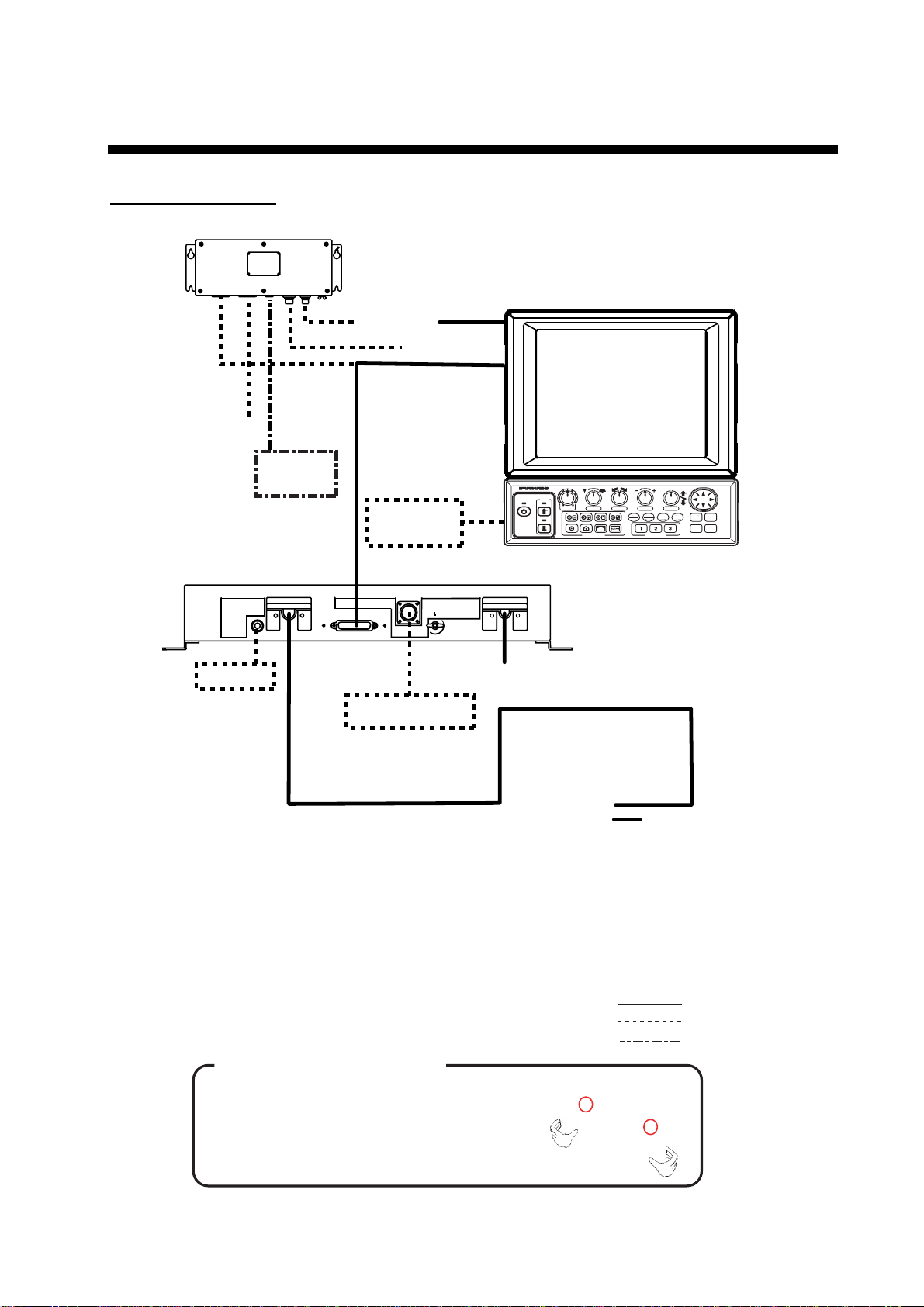
SYSTEM CONFIGURATION
CH-270 (350 stroke)
INTERFACE UNIT
IF-8000
DISPLAY UNIT MU-100C
Navigator
Control Unit
Display
Unit
External
Monitor
Remote
Controller
XDR
GAIN
POWER
SECTOR TRAIN
DISPLAY MODE
RANGE
TILT
FULL
MAIN
FAST
BRILL
TARGET
HALF
SUB
SCAN
CUSTOM MODE
MENU
R/B
EVENT
HULL UNIT
SPEAKER
DATA/VIDEO OUT
MOTION SENSOR
12-32VDC
Speaker
Motion Sensor
Note 1: The CH-270 is supplied
with or without a display
unit. For connection of
locally supplied monitor, an
interface unit is provided.
The drawing above shows
the system configuration
with the MU-100C.
Note 2: For use of a locally
supplied monitor, connect
it and control unit to the
interface unit.
How to remove the hard cover
(system with locally supplied monitor only)
Place your thumbs at the locations shown with
circles in the illustration at right, and then lift the
cover while pressing it with your thumbs.
CONTROL UNIT CH-252
TRANSCEIVER UNIT
CH-273
12-32 VDC
12/24 VDC
HULL UNIT
CH-181
: Standard
: Option
: Local Supply
ix
Page 12
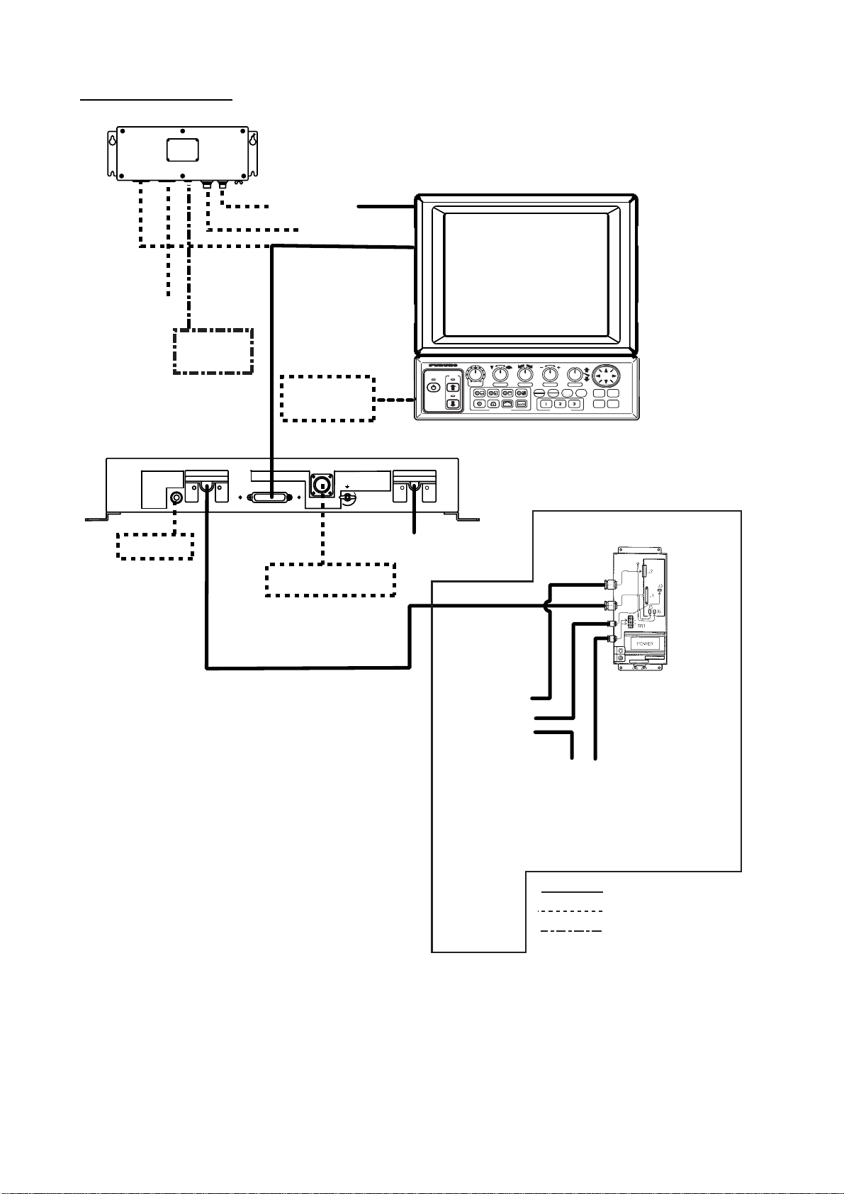
SYSTEM CONFIGURATION
CH-270 (250 stroke)
DIsplay Unit
External
Monitor
INTERFACE UNIT
IF-8000
Navigator
Control Unit
Remote
Controller
DISPLAY UNIT MU-100C
XDR
GAIN
POWER
SECTOR TRAIN
DISPLAY MODE
RANGE
TILT
FULL
MAIN
FAST
BRILL
HALF
SUB
CUSTOM MODE
TARGET
SCAN
CONTROL UNIT CH-252
MENU
R/B
EVENT
HULL UNIT
SPEAKER
DATA/VIDEO OUT
MOTION SENSOR
Speaker
Motion Sensor
Note 1: The CH-270 is supplied
with or without a display
unit. For connection of
locally supplied monitor, an
interface unit is provided.
The drawing above shows
the system configuration
with the MU-100C.
Note 2: For use of a locally
supplied monitor, connect
it and control unit to the
interface unit.
12-32VDC
12-32 VDC
TRANSCEIVER UNIT
CH-273
CONTROL BOX
12/24 VDC
HULL UNIT
CH-184
: Standard
: Option
: Local Supply
x
Page 13
1. OPERATIONAL OVERVIEW
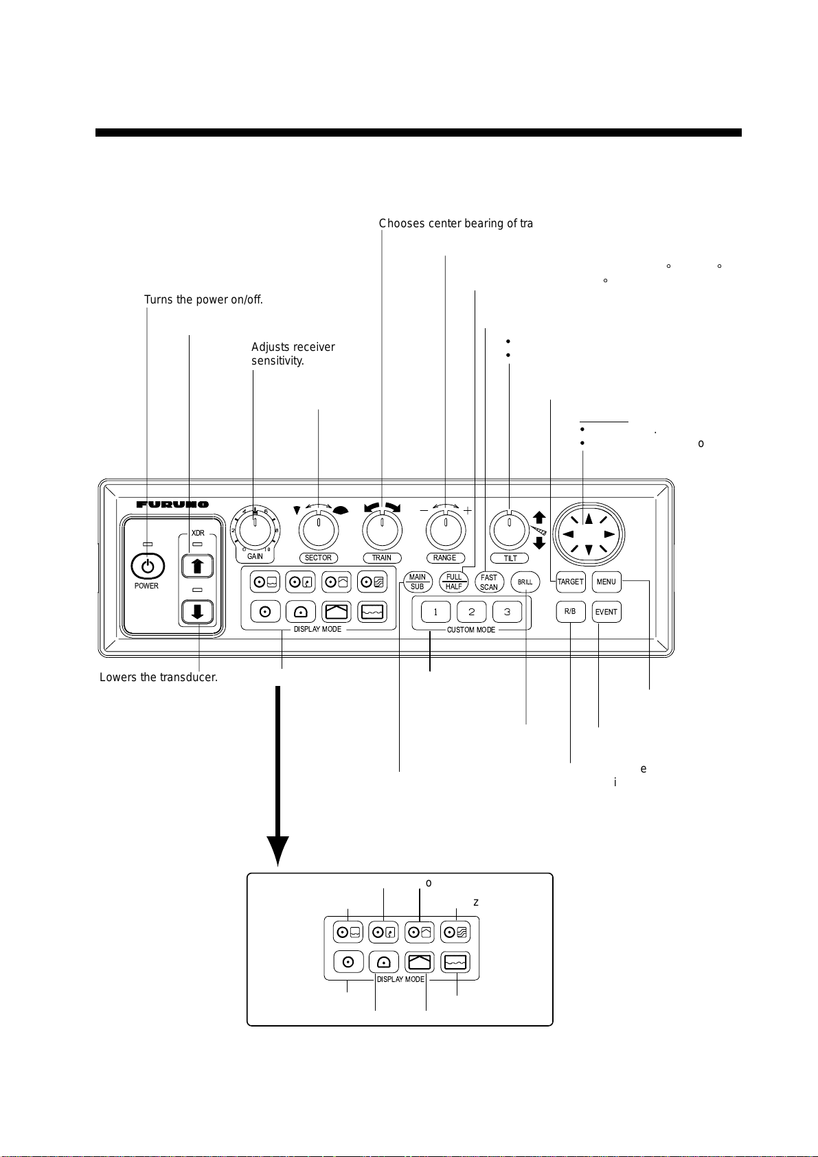
1.1 Control Description
Chooses center bearing of training sector.
Chooses detection range.
Switches training sector between 180° and 360°.
Turns the power on/off.
Raises the transducer.
Adjusts receiver
sensitivity.
Chooses width of
training sector.
(horizontal mode), or 180
Chooses scan speed (sonar)/picture
advancement speed (echo sounder).
=
Controls tilt angle.
=
Selects center direction of
the vertical scanning sector.
Turns target lock on/off.
°
(vertical scan mode).
Omnipad
=
Shifts cursor.
=
Selects menu items, options.
XDR
POWER
Lowers the transducer.
GAIN
SECTOR TRAIN
DISPLAYMODE
Choose display mode.
Horizontal/Video Plotter
Horizontal/History
MAIN
SUB
RANGE
FULL
HALF
CUSTOM MODE
FAST
SCAN
TILT
BRILL
Provide short-cut
key or one-touch
setup.
Adjusts display
brilliance* and
panel dimmer.
Swithes control between
main and sub windows in
combination displays.
Sub window is circumbscribed
with a red rectangle when it
is selected.
Horizontal/Vertical Scan
Horizontal/Strata
TARGET
MENU
R/B
EVENT
Opens/closes
menu.
Inscribes/erases event
marker.
Inscribes/erases range
and bearing markers.
* FURUNO
monitor
only.
DISPLAYMODE
Horizontal
Horizontal Expansion
Echo Sounder
Vertical Scan
Control unit
1-1
Page 14
1. OPERATIONAL OVERVIEW
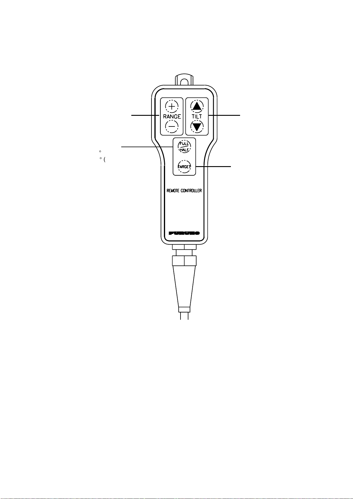
1.2 Remote Controller
The Remote Controller CH-256 (option) provides armchair control over range, tilt, target
lock and training range.
Choose display
range.
Chooses training range.
for full circle 360° (horizontal mode)
or half circle 180° (vertical scan mode).
Choose tilt angle.
Enables/disables
target lock.
Remote controller
Note: The remote controller can also be used with a commercial monitor.
1-2
Page 15
1. OPERATIONAL OVERVIEW
1.3 Turning the Power On/Off
1.3.1 Power on
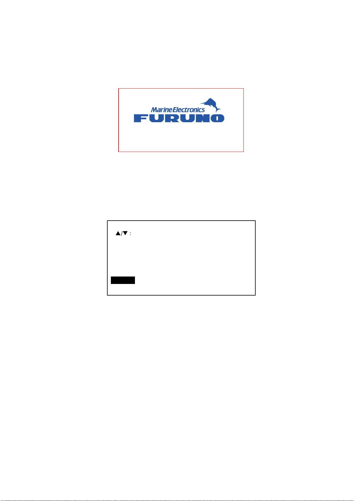
Press the [POWER] switch on the control unit until you hear a “click.” A beep sounds, the
lamp above the switch lights and the startup display appears (for four seconds).
MODEL : CH-270 180kHz
Startup display
Note 1: Wait at least five seconds before reapplying the power.
Note 2: The first time the power is applied after installation, the language selection screen
appears. English is selected; press the [MENU] key to erase the screen and
continue.
Please set language.
([p/q]: Select, [MENU]: Enter)
XXXX ... For Japanese Customer
XXXX
English
(Japanese)
Language selection screen
Note 3: The example screens shown in this manual may not match the screens you see on
your display. The screen you see depends on your system configuration and
equipment settings.
1-3
Page 16

1. OPERATIONAL OVERVIEW
1.3.2 Power off
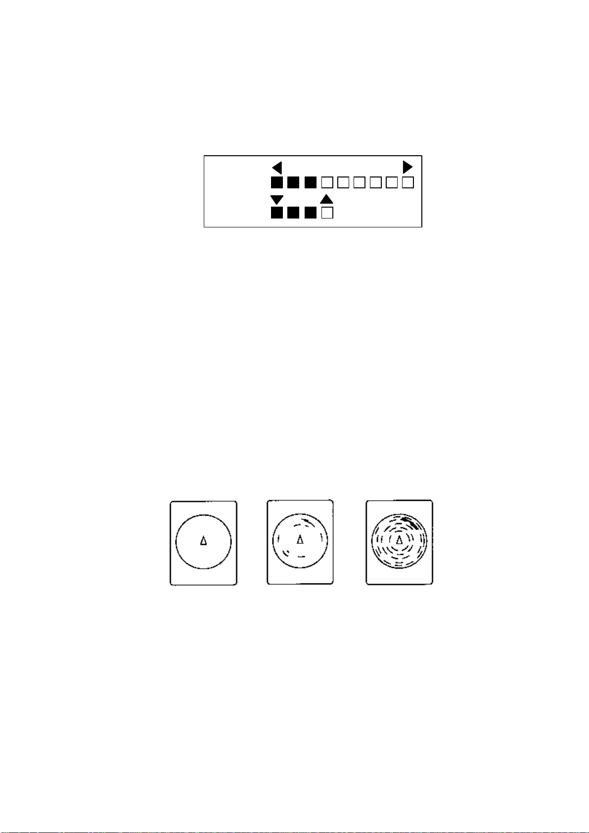
1. Press the [©] switch on the control unit. The lamp above the switch blinks while the
transducer is being raised and lights steadily when it is fully raised.
30
25
Transducer status indicator
• Up arrow is filled when transducer
has been retracted into the tank.
• Down arrow is filled when transducer
has been fully lowered.
• Appropriate arrow flashes during
raising/lowering of transducer.
NOTE: When the transducer is being
raised automatically (auto raise feature),
the arrows are filled and the up arrow
flashes. When the transducer has been
fully retracted, the up arrow lights
and the down arrow becomes hollow.
Transducer status indicator
2. Press the [POWER] switch after the lamp above the [©
] switch lights steadily.
Note 1: The transducer is automatically retracted into the tank if the [POWER] switch is
pressed before retracting the transducer. However, for safety purposes, make it a
habit to retract the transducer before turning off the power.
Note 2: After changing settings, wait at least one minute before turning off the equipment to
allow the equipment to memorize settings. This will enable the equipment to start
up with the last-used settings. No harm will result to the equipment if this is not
done.
Note 3: The hull unit remains powered when power is turned off at the control unit.
Therefore, if the sonar is not to be used for a long period turn it off at ship’s mains
switchboard.
1-4
Page 17

1. OPERATIONAL OVERVIEW
1.4 Raising, Lowering the Transducer
1.4.1 Lowering the transducer
With the boat at the fishing ground, press the [ª] switch to lower the transducer. The lamp
above the switch blinks while the transducer is being lowered and lights when it is
completely lowered. The down arrow on the transducer status indicator is filled when the
transducer is completely lowered.
CAUTION
Do not exceed 20 knots when operating
the equipment and do not exceed 15
knots when lowering or raising the
transducer.
The transducer may become damaged.
1.4.2 Raising the transducer
Press the [©] switch to raise the transducer. The lamp above the switch blinks while the
transducer is being raised and lights steadily when it is fully raised. The up arrow of the
transducer status indicator is filled when the transducer is fully raised.
Note 1: With speed input, the transducer can be automatically raised when the ship’s speed
exceeds a speed between 5 and 15 knots. For further details about the automatic
retraction feature, see AUTO RETRACTION in paragraph 5.4.3.
Note 2: Audio and visual alarms may be released when ship speed goes higher than
allowed for a certain transducer operation. For further details, see SPEED ALARM
MESSAGE in paragraph 5.4.3.
1-5
Page 18
1. OPERATIONAL OVERVIEW
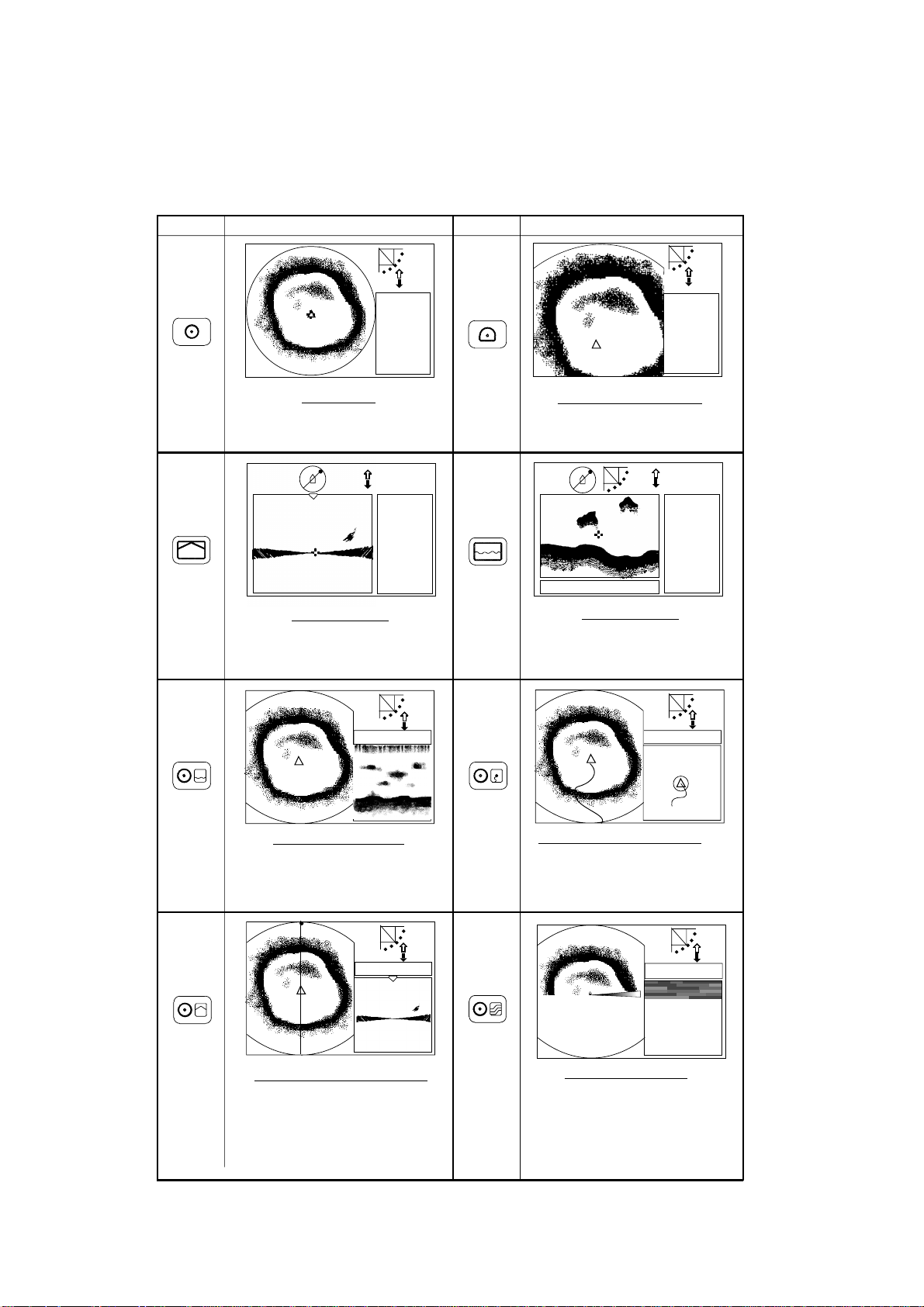
1.5 Choosing a Display
This s onar has eight display modes and you may choose one with one of the DISPLAY
MODE keys. Refer to the chapter shown in the illustration for more information about each
mode.
Key
Picture
NAV
DATA
HORIZONTAL
This mode provides 360 degree coverage.
Useful for general search. (Chapter 2)
NAV
DATA
VERTICAL SCAN
Vertical section of underwater conditions
appears on the entire screen. (Chapter 3)
Key
Picture
NAV
DATA
HORIZONTAL EXPANSION
Zoomed horizontal picture appears over
the entire screen. (Chapter 2)
NAV
DATA
or
A-SCOPE
DISPLAY
Water temp/depth
ECHO SOUNDER
Using a fixed spot beam this display
shows fish echoes below or around the
vessel. (Chapter 4)
NAV DATA
HORIZONTAL/HISTORY
The horizontal picture appears in the main
window; the history picture in the sub
window. Useful for showing history of fish
movement, distribution. (Chapter 2)
NAV DATA
HORIZONTAL/VERTICAL SCAN
The horizontal picture appears in the main
window; the vertical scan picture in the sub
window. Note that the vertical scan display
may be located below the horizontal
display, with both displays nearly equal
in size. (Chapter 3)
NAV DATA
HORIZONTAL/VIDEO PLOTTER
The horizontal picture appears in the main
window and the video plotter picture, which
traces ship's track, in the sub window.
(Chapter 2)
NAV DATA
HORIZONTAL/STRATA
The horizontal picture appears in the main
window; the strata picture in the sub window.
The strata picture shows bottom undulatons
in different colors. It is useful in bottom
trawling to avoid projections. (Chapter 2)
1-6
Display m odes
Page 19
1. OPERATIONAL OVERVIEW
1.6 Adjusting Screen Brilliance, Panel Dimmer
Screen brilliance can be adjusted in nine levels and the panel dimmer (backlighting) in four.
1. Press the [BRILL] key to open the dialog box for screen brilliance and panel dimmer. Do
the next step within four seconds; otherwise the dialog box will be erased.
BRILL:3
DIMMER:3
Brilliance, panel dimmer dialog box
2. Operate ◄ or ► to adjust screen brilliance (0 is the lowest brilliance; 9 the highest). The
[BRILL] key may also be operated to adjust brilliance.
3. Operate ▲ or ▼ to adjust the panel dimmer (0 is the lowest level; 4 is the highest).
4. Press the [MENU] key to register settings and close the dialog box. Note that the dialog
box is automatically erased if there is no control operation within about four seconds.
Note: The brilliance of a commercial monitor cannot be adjusted with the [BRILL] key. Use
the associated control on the monitor.
1.7 Adjusting the Gain
The [GAIN] control adjusts the sensitivity of the receiver. Normally, the control is adjusted so
that the bottom echo is displayed in reddish-brown mixed with red. Initially set the gain
between “4” and “6” and then fine tune according to fishing ground, etc.
Too Low Proper
Too High
How to adjust the gain
1-7
Page 20
1. OPERATIONAL OVERVIEW
1.8 Basic Menu Operation
The menu, consisting of seven menus, mostly contains items which once preset do not
require frequent adjustment. Below is the procedure for basic menu operation.
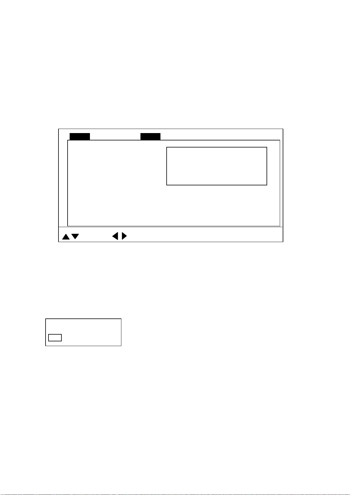
1. Press the [MENU] key to open the menu. The last-used menu is displayed. (In the
example below, the COM2 menu is shown.)
Note: Either PRESET or SHORT-CUT appears between ES and SYS at the top of the
menu depending on the setting of CUSTOM KEY on the SYSTEM SETTING 1
menu. For further details, see paragraph 5.3.
MENU
DELETING TRACK NO
WHITE MARKER OFF
SIG LEVEL OFF
COLOR 16
BKGD COLOR 2
: SELECT
COM1 HORZ VERT ES PRESET SY SCOM2
Dialog box appears here when
a menu item is selected.
: CHANGE MENU: END
COM2 menu
2. To choose a menu, press ▲ to choose MENU at the top of the screen (if it is not already
chosen) and then press ◄ or ► to choose menu desired.
3. Press ▲ or ▼ to choose menu item desired. Menu help is provided at the bottom of the
screen.
4. Press ► to open the corresponding dialog box. The example below shows the dialog
box for DELETING TRACK in the COM2 menu.
DELETING TRACK
NO YES
Dialog box for deleting track
5. Press ◄ or ► to choose option desired. If input of numeric data is required, use ◄ or ►
to lower or raise the figure, respectively.
6. Press ▲ or ▼ to close the dialog box and return to the menu, or press the [MENU] key
to register your selection and close the menu.
1-8
Page 21
2. HORIZONTAL MODE
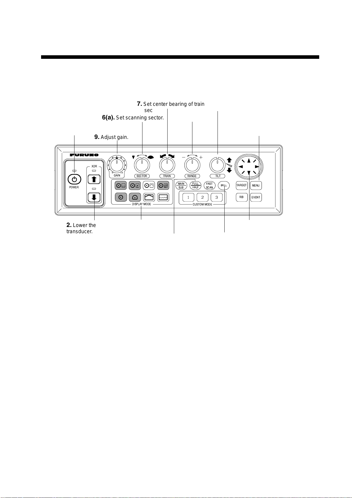
2.1 Operational Overview
The figure below shows the typical horizont al mode operating sequence.
7.
1.
Turn on the power.
POWER
6(a).
9.
Adjust gain.
XDR
Set center bearing of train
sector.
Set scanning sector.
GAIN
SECTOR TRAIN
DISPLAYMODE
5.
Set range.
MAIN
SUB
RANGE
FULL
HALF
CUSTOM MODE
FAST
SCAN
8.
TILT
Set tilt angle.
BRILL
TARGET
R/B
11.
(ex. TVG) as required.
MENU
EVENT
Adjust menu settings
2.
Lower the
transducer.
4.
Select appropriate
horizontal mode.
6(b).
Select training sector for
full circle.
Control unit
10.
Measure range and
bearing to target with cursor.
3.
Adjust screen
brilliance.
2-1
Page 22
2. HORIZONTAL MODE
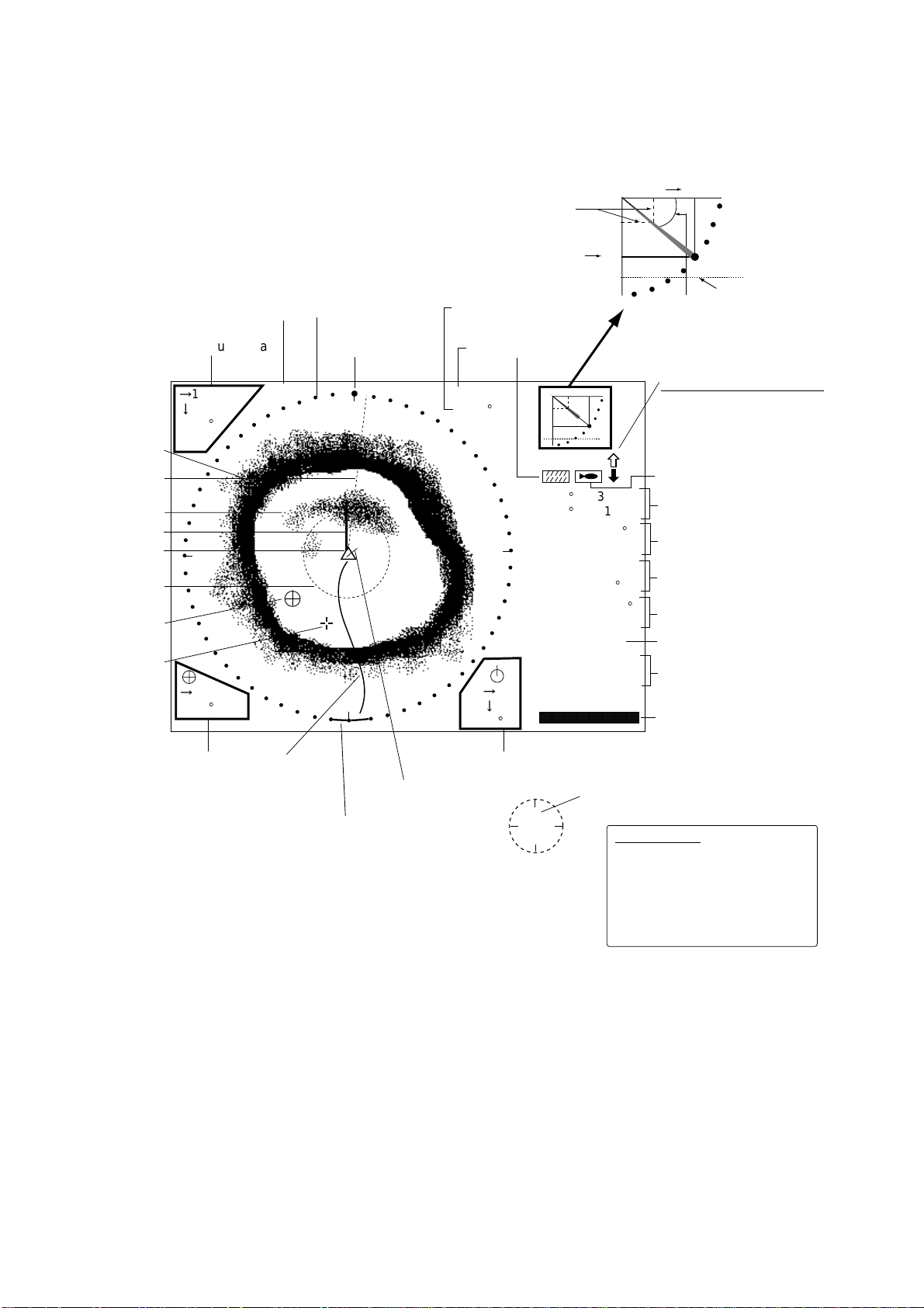
2.2 Typical Horizontal Mode Display
Horizontal max. range
Range and bearing markers
Tilt angle indicator
(Indicates transducer tilt angle.)
30
Bottom
echo
Bearing
marker
Fish echo
ETA marker
Own ship
marker
Range
marker
Event
marker
Cursor
Demonstration
mode
Cursor data
16
13
B208
°
+
W
16
B234
°
(DEMO)
Sector marker
Train indicator
N
S
Tilt angle
Range
R 40 m
T 40
°
B7
Vertical max.
25
depth
Interference
rejector
30
25
34° 12. 343' N
134° 34. 213' W
CSE 357
SPD 9.9 kt
E
DEP 35 m
TMP 12.3°C
CUR 11.0°
CUR 11.0˚
2.0 kt
2.0 kt
GAIN 5.3
TVG LEVEL 4.0
DISTANCE 200 m
9
COLOR
8
°
Tilt angle
(See note
below.)
Transducer status indicator
Filled arrow: Respective
action completed
Blinking arrow: Action in
progress
Target lock indicator
Position in latitude*,
Depth marker
longitude*
°
Course*, speed*
Depth,
water temperature*
Tide direction*,
tide speed*
Gain setting
TVG level,
distance settings
Color bar
Event
marker
data
Ship's
track*
Current
vector*
Sweep indicator
(Shows train position
in horizontal mode.)
Range and bearing
markers data
N
W
E
S
sensor.
North marker*
Depth marker
When depth data is input from
external equipment, the depth
marker shifts according to depth
data. If the depth data is greater
than the horizontal range, the
depth marker disappears.
Typical horizontal mode dis play
With the tilt angle lowered, your ship is at the cent er of the screen. The bottom, which
appears in r eddish-brown c olor, i s dis played as a circle and f ish echoes appear wi thin the
circle.
* Requires appropriate
2-2
Page 23
2. HORIZONTAL MODE
2.3 Choosing the Range
The [RANGE] control chooses the detection (display) range. Choose the range according
to either the fish species being searched or the depth desired. 15 ranges are available.
SEA SURFACE
SEA SURFACE
Range indicated
on the screen.
BOTTOM
BOTTOM
How to choose the range
Range indicated
on the screen.
Default horizontal mode range settings
Range No. Meters Feet
1 10 40
2 20 80
3 40 120
4 60 200
5 80 300
6 100 400
7 120 500
8 160 600
9 200 700
10 250 800
11 300 1000
12 400 1200
13 500 1500
14 600 2000
15 800 2500
Normally, the range is set so that the bottom is traced at the lower part of the screen (like
an echo sounder). Each time the [RANGE] control is operated the newly chosen range
briefly appears in large characters at the screen top. Range is always displayed at the top
right-hand corner of the screen.
Note 1: Unit of range measurement may be chosen from among meters, feet, fathoms,
passi/braza and Hiro (Japanese), with UNIT on the SYSTEM SETTING 1 menu.
For further details, see UNIT in paragraph 5.4.2.
Note 2: Ranges may be freely preset as desired. For further details, see paragraph 5.4.4.
2-3
Page 24
2. HORIZONTAL MODE
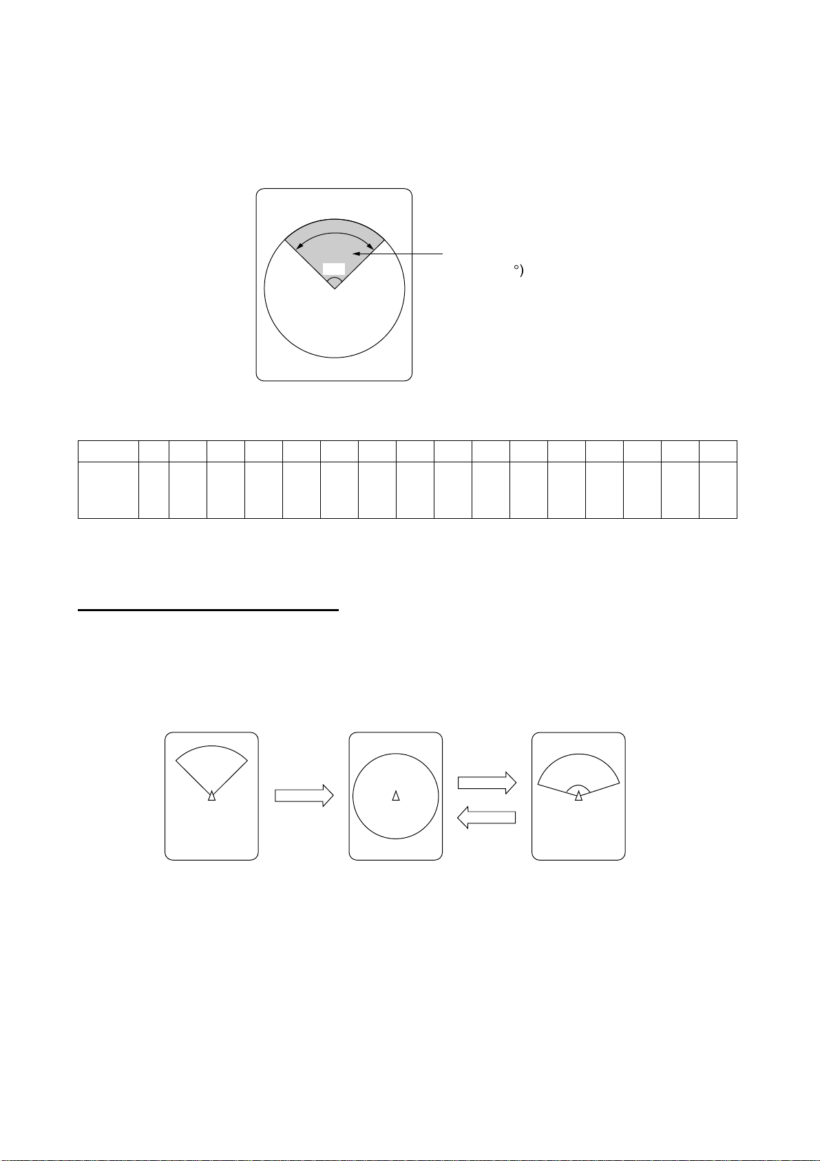
2.4 Choosing Sector Width
Sector means the width of the transducer training. The [SECTOR] control chooses the
training (display) area among the sixteen positions shown in the table below. Clockwise
rotation of the control increases the sector width; counterclockwise rotation decreases it.
Display sector
96°
Display sector
(shown: 96°)
1 2 3 4 5 6 7 8 9 10 11 12 13 14 15 16
Sector
width
(°)
6 24 48 72 96 120 144 168 192 216 240 264 288 312 336 360
In the full-circle mode (360°) the direction of training is clockwise; in the half-circle mode
the direction is clockwise to counterclockwise alternately.
One-touch selection of 360°°°° sector
Each pressing of the [FULL/HALF] key alternately chooses 360° sector (full circle) or 168°
sector (half circle). If the [SECTOR] control is operated following the selection of the
full-circle display, the next pressing of the [FULL/HALF] key presents the full-circle display.
Sector set with
SECTOR control
FULL/HALF
key
Full circle
FULL/HALF
key
Half circle
168
°
2-4
How the FULL/HALF key works
Page 25

2. HORIZONTAL MODE
2.5 Choosing Train Center
The [TRAIN] control chooses the center direction of the detection range. The range of
adjustment is 0° to 354° in increments of 6°. The chosen bearing is shown with a filled
circle, the train indicator, on the bearing scale.
0° (360°) → 6° → 12° → 18° → ... 354°
Train indicator
Sector
Train center
2-5
Page 26

2. HORIZONTAL MODE
2.6 Choosing the Tilt Angle
2.6.1 Choosing the tilt angle
The tilt angle shows the direction to which the sound wave is emitted. When the sound
wave is emitted horizontally, the tilt angle is said to be 0° and when emitted vertically, 90°.
To set a tilt angle, operate the [TILT] control. Watch the tilt angle indication and the tilt
angle indicator at the top right corner of the screen. The tilt angle can be set in increments
of 1°, from +5° (upward) to 90° (downward). Automatic tilt selection is also available. See
AUTO TILT on page 2-24 for details.
Choose the tilt angle depending on target fish. For surface fish choose a small angle
(about 5°) to minimize sea surface reflections and for bottom fish, a large angle (about
40°) to search a wide area.
Soundome
+5
°
0°Horizontal direction
Transducer
90°Vertical direction
Sounding beam and tilt angle
Tilt angle setting range
2-6
Page 27
2. HORIZONTAL MODE
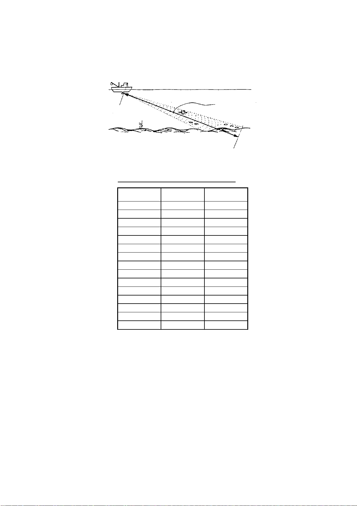
2.6.2 Relation between tilt angle and echo
Refer to the illustration below to see the relation between tilt angle and bottom echo.
Case 1: Tilt angle 30°°°° to 40°:
captured by the full width of the beam.
Case 2: Tilt angle 10°°°° to 20°:
captured by the lower half of the beam.
Case 3: Tilt angle 0°°°° to 5°:
returning echo is weak.
The figure below illustrates how two fish schools “a” and “b” are displayed on the screen
using three different tilt angles.
Case 1(Tilt angle 30°°°° to 40
Case 2(Tilt angle 10°°°° to 20
Case 3(Tilt angle 0°°°° to 5
°: This tilt angle will display the entire bottom since it is
°: °:
°: This tilt angle will only display half the bottom since it is only
°: °:
°: This tilt angle may or may not capture the bottom since the
°: °:
°):
°): Fish school is obscured by the bottom.
°):°):
°):
°): Fish school is located above the bottom (midwater).
°):°):
°):
°): Fish school is located close to the bottom.
°):°):
Case 1
Fish school "a"
Bottom
Case 1
Case 2
Fish school "a"
Bottom
Fish echo and tilt angle
Case 2
Case 3
Fish school "a"
Bottom
Fish school "b"
Case 3
2-7
Page 28
2. HORIZONTAL MODE
Points to consider
• Normally, a vertically distributed fish school is a better sonar target than the bottom,
because it reflects the transmitted pulse back toward the transducer.
• In case 3, both fish schools “a” and “b” are presented. Generally speaking, however,
midwater fish schools tend to be larger than bottom fish schools and they are often
displayed near the bottom on the display.
• It is difficult to detect bottom fish when they are not distributed vertically.
2.6.3 Tilt angle for surface fish
Sound emitted from the sonar transducer forms an oval-shaped beam with a width of
approximately 8° in the vertical direction (vertical beam width). The tilt angle is indicated
by the angle between the center line of the beam and the horizontal plane. Then, if the tilt
angle is set to 0°, the center line is parallel with the sea surface and one half of the
emitted sound goes upward, toward the sea surface.
This causes one half of the emitted sound to be reflected toward the transducer and
displayed on the screen as sea surface reflections. When the sea is calm, since the sound
is reflected just like a light hitting a mirror at a narrow incident angle, it propagates away
and the sea surface reflections become negligible.
However if the sea is not calm enough, they will become dominant and interfere with
observation of wanted echoes. To minimize these sea surface reflections and to search
fish schools effectively, the tilt angle is usually set between 5° and 6° so the upper portion
of the beam becomes almost parallel with the sea surface. When the sea is rough, the tilt
angle is slightly increased to lessen the affect of sea surface reflections.
Tilt angle 0°
Tilt angle 5-7°
Tilt angle
Sea surface
8°
Sea surface
8°
2-8
Page 29
2. HORIZONTAL MODE
2.6.4 Suitable tilt angle
The figure below illustrates the relationship among tilt angle, depth and detection range.
Refer to it to find out the suitable tilt angle for a given depth/detection range.
Tilt angle and beam coverage (frequency 180 kHz, vertical beamwidth 8
20(40)
40(80)
60(120)
80(160)
100(200)
Depth (m)
200(400)
Vertical width of sonar beam
8°
100
(200)
100 m
14 m
200
(400)
200 m
28 m
300
(600)
300 m
42 m
° at -3 dB
400
(800)
)
Range (m)
0
°
5
°
10
°
15
°
Tilt angle and beam coverage
2-9
Page 30
2. HORIZONTAL MODE
2.7 Choosing the Training Speed
The training speed determines how fast the transducer scans the sounding sector. Two
choices are available, normal speed and high speed, and one may be chosen with the
[FAST SCAN] key. Each time the key is pressed, “NORM” (normal speed) or “FAST” (high
speed) momentarily appears at the screen top.
Normal (6°): 60 transmissions required to complete the full 360° picture.
High (12°): 30 transmissions required to complete the full 360° picture.
The time required to train a full circle depends on range used and other factors. The table
below shows the time required to complete one full circle on each range.
Range 1 2 3 4 5 6 7 8 9 10 11 12 13 14 15
Unit ft 40 80 120 200 300 400 500 600 700 800 1000 1200 1500 2000 2500
Time
required
(sec) for
one full
circle
Unit m 10 20 40 60 80 100 120 160 200 250 300 400 500 600 800
Time
required
(sec) for
one full
circle
Norm 11 11 11 11 11 11 13 15 17 20 25 30 37 49 61
Fast 11 11 11 11 11 11 12 14 15 16 19 21 25 31 37
Norm 11 11 11 11 11 11 11 14 17 21 25 33 41 49 65
Fast 11 11 11 11 11 11 11 13 14 16 18 22 26 30 38
Note 1: The above values are for reference purposes. The actual training speed may vary.
Note 2: The range setting must be at least 160 meters to activate high-speed training.
2.8 Finding Echo Position with the Cursor
The cursor measures horizontal range, depth and bearing. Operate the Omnipad to place
the cursor where desired. Cursor position data appears at the top left-hand corner on the
screen.
Cursor position data
®
: Horizontal range
¯
: Depth
B: Bearing
NAV
DATA
2-10
Cursor
Location of cursor position data
Page 31

2. HORIZONTAL MODE
2.9 Event Marker
The event marker functions to m ark im portant locations on the screen, and five may be
inscribed. Each time the [EVENT] key is pressed the “latest event marker” (
at the cursor location and all previously entered event markers are shown by the “previous
event marker” (+). When the capacity for event markers is reached, the eldest event
marker is erased from the screen to make room for the latest.
Note 1: With position data input the event marker moves with ship’s movement. The
event marker can be inscribed without position data, however it will be stationary.
Note 2: The event marker cannot be inscribed from the sub window (strata, hist ory and
video plotter displays). It can only be inscribed from the main window.
Note 3: The latitude and longitude posit ion of the event marker can be output to a video
plotter and that position inscribed on the plot t er’s screen with the external
waypoint mark (X). Each press of the [EVENT] key outputs event m arker position.
For further details, see TARGET L/L in paragraph 5.4.2.
Note 4: The tilt angle must be less than 75 degrees to use this feature.
⊕
) is inscribed
2.9.1 Inscribing the event marker
1. Operate the Omnipad to place the cursor on the location desired for an event marker.
2. Press the [EVENT] key to inscribe the event marker. Event marker data appears at the
bottom left-hand corner.
"Latest event
marker"
Display area
"Previous event marker"
Event marker data
→: Horizontal range
B: Bearing
NAV
DATA
To delete all event markers,
place the cursor outside the
display area and press the
[EVENT] key.
How to use the event marker
2-11
Page 32

2. HORIZONTAL MODE
2.9.2 Deleting all event markers
All event markers can be erased from the screen as follows:
1. Operate the Omnipad to place the cursor outside the display area.
2. Press the [EVENT] key to show the following dialog box. Do the next step within four
seconds; otherwise the dialog box will be erased.
DELETE EVENT MARK?
NO YES
3. Press ► to choose YES and then press the [MENU] key. All event markers are then
erased from the screen.
2.10 Depth and Horizontal Range Markers
The horizontal range, depth and bearing to a fish school can be measured by using the
range and bearing markers.
1. Operate the Omnipad to place the cursor on the location desired.
2. Press the [R/B] key to display the range and bearing markers. Horizontal range, depth
and bearing to the cursor location are shown at the bottom right-hand corner of the
screen.
3. To erase the range and bearing markers, place the cursor at the intersecting point of
the depth and horizontal markers or outside the display area and then press the [R/B]
key.
NAV
Bearing marker
DATA
2-12
Range marker
Range and bearing
markers data
→:Horizontal range
↓: Depth
B: Bearing from ship's bow
Range and bearing markers
Page 33

2. HORIZONTAL MODE
2.11 Adjusting the Picture
2.11.1 Suppressing bottom and surface reflections
In shallow fishing grounds, excessive sea surface and bottom reflections often interfere
with wanted fish echoes and they cannot be eliminated sufficiently with the TVG controls.
In such cases, try to reduce the output power, without turning down the gain. The picture
becomes clearer when output power is reduced rather than when the gain is decreased.
1. Press the [MENU] key to open the menu.
2. Press ▲ to choose MENU and then press ◄ to choose the COM1 menu.
MENU
TX POWER MAX
PULSELENGTH LONG
TX RATE 10
INT REJECT OFF
AGC OFF
AUDIO LEVEL 0
: SELECT
COM1 HORZ VERT ES PRESET SY SCOM2
: CHANGE MENU: END
COM1 menu
3. Press ▲ or ▼ to choose TX POWER and then press ► to show the TX POWER
dialog box.
TX POWER
MAX MIN
4. Press ► to choose MIN. (For long range detection be sure to return the setting to
MAX.)
5. Press the [MENU] key to register your selection and close the menu.
2-13
Page 34

2. HORIZONTAL MODE
2.11.2 Suppressing bottom tail
As described earlier, fish schools near the bottom are sometimes difficult to detect
because you have to discriminate fish echoes from the bottom reflections. To discriminate
fish echoes near the bottom, choose the short Tx pulselength on the COM1 menu to
decrease the tail of bottom reflections.
1. Press the [MENU] key to open the menu.
2. Press ▲ to choose MENU and then press ◄ to choose the COM1 menu.
3. Press ▲ or ▼ to choose PULSELENGTH and then press ► to show the
PULSELENGTH dialog box.
PULSELENGTH
LONG SHORT
4. Press ► to choose SHORT. For long-range detection, be sure to return the setting to
LONG.
5. Press the [MENU] key to register your selection and close the menu.
2.11.3 Displaying weak echoes clearly
Echoes from targets (such as the bottom or a fish) return to the transducer in order of the
distance to them, and when their intensities are compared at the transducer face, those
from nearer targets are generally stronger when their reflecting properties are nearly equal.
The sonar operator will be quite inconvenienced if these echoes are directly displayed on
the screen, since he won’t be able to judge the actual size of the target from the size of
echoes displayed on the screen. To overcome this inconvenience, use the TVG function. It
compensates for propagation loss of sound in water: amplification of echoes on short
range is suppressed and gradually increased as range increases, so that similar targets
are displayed in similar intensities irrespective of the ranges to them.
The TVG also functions to suppress unwanted echoes and noise which appear in a certain
range area on the screen.
Proper TVG setting
Echoes of equal
size targets are
presented in the
same color and size.
Noise is rejected.
Noise caused by
strong reflection
of surface
turbulence.
Without TVG
Nearer target
echoes appear
in larger size.
Reduce
gain for
nearby
areas,
using
TVG.
How TVG works
Note: Excessive TVG may eliminate short-range echoes.
2-14
Page 35

2. HORIZONTAL MODE
To adjust TVG:
1. Press the [MENU] key to open the menu.
2. Press ▲ to choose MENU and then press ◄ or ► to choose HORZ.
MENU
TVG LEVEL 4.0
TVG DISTANCE 4.0
GAIN ADJUST 0
RES. COLOR LO G
CLUTTER 0
TARGET KEY REVERSE
LOCK MODE AUTO
AUTO TILT OFF
: SELECT
COM1 VERT ES PRESET SY SCOM2 HORZ
: CHANGE MENU: END
HORZ menu
3. Press ▲ or ▼ to choose TVG DISTANCE and then press ►. The following dialog box
appears.
GAIN
Hi
TVG DISTANCE
4.0
Lo
200 m
4. Press ◄ or ► to set TVG distance between 3.0 and 5.0 (130-320 m) to decrease
amplification of echoes on short range. As a general rule, use a higher setting for low
frequency transducer; a lower setting for high frequency transducer. The larger the
figure the greater the distance at which TVG works. When you change a TVG setting
(DISTANCE or LEVEL), the TVG line changes from solid to dashed; the solid line
denotes current TVG setting.
TVG Distance
Setting
Meters 3 8 20 40 60 100 130 160 200 250 320
Feet 10 30 70 130 210 330 410 520 660 820 1040
Passi/braza 2 5 10 20 40 60 80 100 120 150 180
Fathoms
0 0.5 1.0 1.5 2.0 2.5 3.0 3.5 4.0 4.5 5.0
5 10 20 40 60 80 100 110 140 170
2
. . . .
. . . .
10.0
1000
3280
600
550
2-15
Page 36

2. HORIZONTAL MODE
5. Press the [MENU] key to register your selection and close the menu.
6. To suppress reflections from the sea surface or plankton, choose TVG LEVEL and
then press ►.
4.0
GAIN
Hi
Lo
TVG LEVEL
200 m
7. Press ◄ or ► to adjust TVG LEVEL, considering sea conditions. The setting range is 0
to 10, however a setting between 2.0 and 5.0 should provide satisfactory results. The
higher the figure the less the gain over distance.
8. Press the [MENU] key to register your selection and close the menu.
Watch a distant fish echo which is approaching own ship. Observe the color of the fish
echo while adjusting tilt angle so the fish echo is within the sounding beam. If the color
and size of the echo stay the same as the echo approaches own ship, the TVG setting is
proper. If the echo suddenly becomes smaller, the TVG level may be too high.
2-16
Page 37

2. HORIZONTAL MODE
2.11.4 Erasing weak echoes
Weak echoes such as interference can be erased from the screen. This is useful when
you want to observe a fish school echo.
1. Press the [MENU] key to open the menu.
2. Press ▲ to choose MENU.
3. Press ◄ or ► to choose COM2.
MENU
DELETING TRACK NO
WHITE MARKER OFF
SIG LEVEL OFF
COLOR 16
BKGD COLOR 2
: SELECT
COM1 HORZ VERT ES
: CHANGE MENU: END
COM 2 menu
4. Press ▲ or ▼ to choose SIG LEVEL.
5. Press ► to open the dialog box.
SIG LEVEL
OFF
1
(OFF, 1-14)
OFF
14
SHORT-CUT
8-color display: OFF, 1-6
16-color display: OFF, 1-14
SYSCOM2
Signal level dialog box
6. Press ◄ or ► to choose echo color to erase. Pressing ► erases echoes from weak to
strong in ascending order of strength. You can see which echo color is erased by
watching the color bar.
7. Press the [MENU] key to register your selection and close the menu.
2-17
Page 38

2. HORIZONTAL MODE
2.11.5 Enlarging fish echoes (horizontal expansion display)
Fish echoes may be enlarged by us ing the horizontal expansion display. Press the
key to show the horizontal ex pansion display. The direction of expansion de pends on the
train di r ec tion as shown in the table below.
Train center direction Position after expansion Remarks
318° – 42° Moves to screen bottom For viewing forward
48° – 132° Moves to left side of screen For viewing starboard side
138° – 222° Moves to screen top For viewing aft
228° – 312° Moves to right side of screen For viewing port side
Train
position
Own ship
marker
Cursor position data
→14
↓ 12
B46
°
+
Sector marker
Train indicator
Tilt angle
Range
R 40 m
T 40
°
25
34° 12. 343' N
134° 34. 213' W
CSE 357
SPD 9.9 kt
DEP 35 m
TMP 12.3˚C
CUR 11.0°
CUR 11.0˚
2.0 kt
2.0 kt
GAIN 5.3
30
°
2-18
Cursor
Horizontal expansion display
TVG LEVEL 4.0
DISTANCE 200 m
COLOR
Page 39

2. HORIZONTAL MODE
2.12 Target Lock
Three types of target lock modes are available.
Manual reverse: The transducer train direction is reserved manually. This is the default
target lock function setting and it may be used in both horizontal and
vertical scan modes.
Position: Tracks stationary position (such as a reef) using position data from a
navigator. Available in the horizontal mode.
Echo: Tracks fish echo either manually or automatically. Available in the
horizontal mode.
2.12.1 Choosing target lock mode
1. Press the [MENU] key to open the menu.
2. Press ▲ to choose MENU and then press ◄ or ► to choose the HORZ menu.
3. Press ▲ or ▼ to choose TARGET KEY.
4. Press ► to show the following dialog box.
TARGET KEY
REVERSE POS ECHO
5. Press ◄ or ► to choose option desired.
6. Press the [MENU] key to register your selection and close the menu.
2.12.2 Manual reverse mode
The transducer train direction is reversed manually, thereby emphasizing possible fish
echoes.
Note: This function is inoperative in the echo sounder mode. In the vertical scan mode the
manual reverse mode is automatically chosen regardless of the setting in
paragraph 2.12.1.
To activate the manual reverse mode:
1. Choose REVERSE following the procedure in paragraph 2.12.1.
2. Press the [TARGET] key to reverse the transducer train direction when a fish school
appears. “REVERSE” momentarily appears at the screen top when the key is pressed
and then the transducer train direction is reversed.
2-19
Page 40

2. HORIZONTAL MODE
2.12.3 Position mode
This mode tracks a stationary position (such as a reef ) using position data fed from a
navigator.
Note 1: If the [TARGET] key is operated when using the horizontal/vertical scan
combination mode, the train ang le is automatically pointed toward target direction
while the target lock marker is displayed. When target lock is canceled the
previously used train angle is restored.
Further, vertical search (see paragraph 5.3.3) is conducted with the vertical scan
mode settings of range, tilt and display range. Note that the horizontal range
settings of the vertical scan mode cover the horizontal m ode range.
Note 2: This mode requires position data. When there is no position data the message
“NO POSITION DATA.” appears for five seconds and tracking is automatically
cancelled. Check the navigator.
Note 3: HORZ RANGE on the VERT menu cannot be adjusted while the position mode is
active. Beeps sound when you attempt to change its setting.
Note 4: The tilt angle must be less than 75 degrees to use this feature.
To use the position mode:
1. Choose POS following the procedure in paragraph 2.12.1.
2. Use the Omnipad to choose the location to track.
3. Press the [TARGET] key.
The message “POS LOCK” appears momentarily at the screen top, the target lock
marker is displayed at the cursor position and the target lock indicator appears at t he
top right-hand corner of the screen while tracking (with position data from external
equipment) is occurring. If the posit ion goes out of the display area, target lock is
automatically cancelled and the target lock indicator and target lock marker disappear.
The train range is fixed at 48° and train and tilt are automatically adjusted to track the
position selected. The [SECTOR], [TRAIN], [TILT], [RANGE] and [FULL/HALF] controls
are inoperative during tracking. When you attempt to operate them the message
“TARGET LOCKING NOW” appears, accompanied by the aural alarm.
Target lock indicator
Target lock marker
Target lock indicator
4. To turn off the target lock, press the [TARGET] key again. The message “LOCK END”
momentarily appears, the target lock marker and the target lock indicator disappear
and previously used sector, train and tilt settings are restored. Also, the latitude and
longitude indication now shows current position.
2-20
Page 41

2. HORIZONTAL MODE
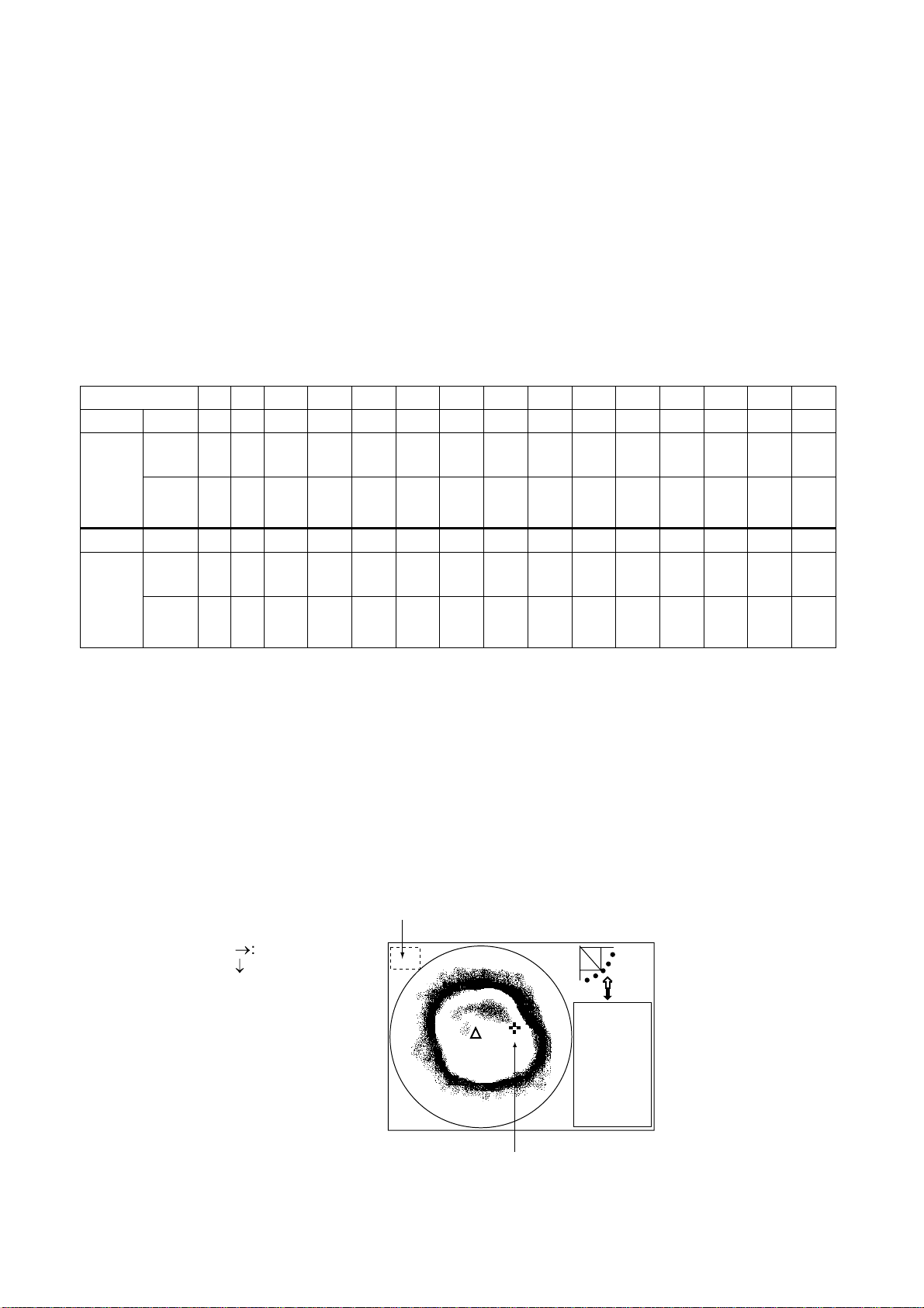
2.12.4 Echo mode
The echo mode tracks a fish school, either automatically or manually. The default setting
is automatic, and you can choose automatic or manual with “LOCK MODE” in the HORZ
menu.
Automatic echo tracking mode
The automatic echo target lock function automatically tracks a fish school appearing in the
operator-chosen target lock area. If the tracked fish school goes out of the area in the
range direction, tracking is suspended until it or a new fish school comes into the area.
To use the automatic echo tracking mode:
1. Choose ECHO following the procedure in paragraph 2.12.1.
2. Set LOCK MODE to AUTO on the HORZ menu.
3. Press the [TARGET] key. The dialog box below appears at the screen center, the
message “ECHO LOCK” appears for three seconds at the top of the screen, the target
lock area appears in the current train area and the target lock indicator appears at the
right-hand side of the screen.
TARGET LOCK AREA.
: INSIDE
: OUTSIDE
4. Use the [SECTOR] and [TRAIN] controls and the Omnipad to set the detection area.
Do not include bottom echoes in the zone, so that target lock will not be activated by
bottom echoes.
When a target of red or reddish-brown color is detected in the target lock area, the
target lock indicator blinks and a buzzer sounds to call the operator’s attention.
Outer limit
Target lock
indicator
NAV
DATA
Inner limit
Target lock area
2-21
Page 42

2. HORIZONTAL MODE
When the fish echo is lost the tilt angle is automatically changed as below to continue
tracking the echo:
Tilt changed to search [(A + 10°) → (A - 10°) →A]
Detection area displayed once again and target
lock indicator lights.
A: Tilt angle at start of target lock
5. To turn off the target lock, press the [TARGET] key again. The message “LOCK END”
appears for three seconds at the screen top, the target lock indicator disappears and
operation continues with current train and tilt settings.
To use the manual echo tracking mode:
1. Choose ECHO following the procedure in paragraph 2.12.1.
2. Choose LOCK MODE to MANUAL on the HORZ menu.
3. Press the [TARGET] key when a wanted target echo appears.
The message “ECHO LOCK” appears along with the target lock indicator. Then, the
transducer train direction is reversed and searching starts with the current tilt angle.
When a target echo appears, the transducer train direction is again reversed
automatically, the buzzer sounds and the target lock indicator blinks.
If the fish echo is lost, the tilt angle is automatically changed as below to continue
tracking.
1. Tilt angle is changed by +10° (A+10°).
(A is the tilt angle used when tracking began.)
2. Tilt angle is changed by -20° (A-10°).
3. If the echo could not be found, tracking is
cancelled and tilt angle A is restored.
4. To quit the target lock, press the [TARGET] key again. The message “LOCK END”
appears momentarily.
2-22
Page 43

2. HORIZONTAL MODE
2.13 Horizontal Menu Overview
This section presents an overview of the items on the HORZ menu.
1. Press the [MENU] key to open the menu.
2. Press ▲ to choose MENU and then press ◄ or ► to choose the HORZ menu.
MENU
TVG LEVEL 4.0
TVG DISTANCE 4.0
GAIN ADJUST 0
RES. COLOR LO G
CLUTTER 0
TARGET KEY REVERSE
LOCK MODE AUTO
AUTO TILT OFF
: SELECT
COM1 VERT ES PRESET SY SCOM2 HORZ
: CHANGE MENU: END
HORZ menu
Horizontal menu description
TVG LEVEL: Compensates for propagation loss of sound in water. For further details, see
paragraph 2.11.3.
TVG DISTANCE: Sets distance at which TVG works. For further details, see paragraph
2.11.3.
GAIN ADJUST: Adjust the gain here when there is disparity in gain level between the
main and sub windows.
RES. COLOR: Sets transfer characteristics of input signal level versus display echo level.
Echo strength is emphasized in order of CUBE, SQUARE, LINEAR, LOG, and you can
observe the characteristics of each by watching the color bar as you change the setting.
LOG: Displays weak to strong echoes in their respective levels. This is the default
setting, and is suitable for general use.
LINEAR: Downplays the weak echoes when compared with LOG. Effective for
suppressing weak echoes such as plankton.
SQUARE: Strong echoes are emphasized more than in LINEAR.
CUBE: Strong echoes are emphasized even more than in SQUARE.
2-23
Page 44

2. HORIZONTAL MODE
CLUTTER: Low intensity echoes, often caused by sediments in water, are painted on the
screen as a large number or random dots. This noise can be suppressed. The higher the
number (setting) the weaker the echoes which are erased.
TARGET KEY: Chooses target lock function among reverse, position and echo. For
further details, see paragraph 2.12.
LOCK MODE: Chooses how to track fish echo in “echo” target lock, automatically or
manually. For further details, see paragraph 2.12.
AUTO TILT: Turns automatic tilt on or off. The choices are ±2°, ±4°, ±6°, and ±10°.
Automatic tilt adjusts the tilt angle in the following sequence:
B → (B-A) → B → (B+A) → B → (B-A) → B → (B+A)…
B: Current tilt angle
A: Auto tilt setting
For example, the tilt angle is 30° and the automatic tilt setting is 4°. Then, the tilt angle is
changed in the following sequence: 30° → 26° → 30° → 34° → 30°→ 26° → 30° → 34°…
2-24
Page 45

2. HORIZONTAL MODE
2.14 Interpreting the Horizontal Display
This section provides information necessary for interpreting the horizontal display.
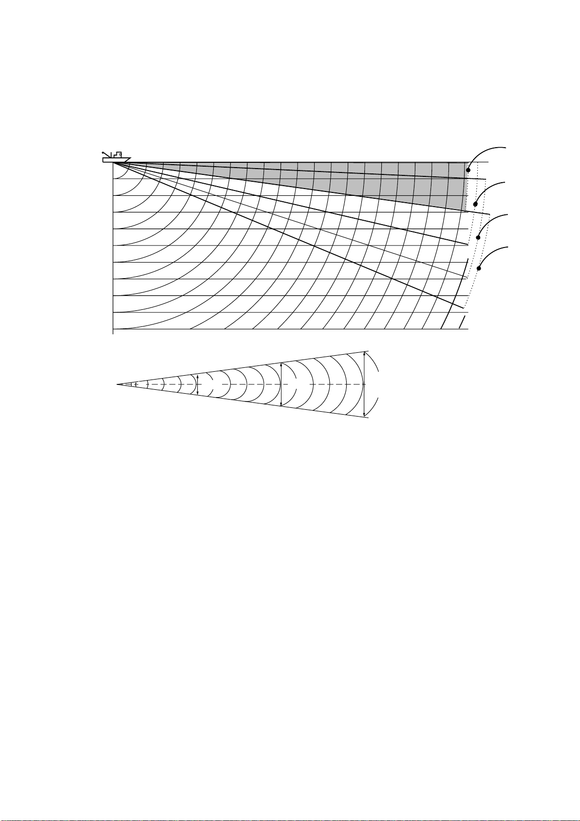
2.14.1 How the horizontal mode picture is painted
As shown below, the search beam is emitted from the soundome at a certain tilt angle.
The information (target echoes) obtained by this beam is displayed in 6° (or 12°) sectors
on the screen. With training through the entire area, a large cone shape area is formed,
providing continuous pictures on the display.
Search Beam Screen Display
Tilt: θ
Search Beam
Training Direction
* 60 transmissions required to complete full circle
(30 in high speed training)
How the horizontal mode picture is painted
Train: 6°*
Tilt: θ
*12° When high speed training is
selected.
2-25
Page 46

2. HORIZONTAL MODE
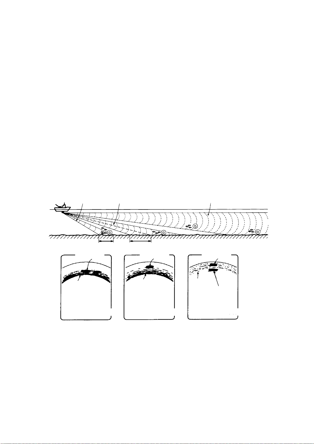
2.14.2 Sample echo displays
Bottom echoes
When the tilt angle is changed, the bottom echo illustrated below will appear on the display.
When the tilt is decreased (toward 0°), the bottom trace becomes wider and weaker. By
observing the bottom condition on the display, you can prevent damage to the net.
(A) Flat bottom
Tilt angle: 10° to 15
(B) Flat bottom
Tilt angle: 20° or more
°
Decreased tilt angle
Only half of
vertical beam width
captures the bottom.
(C) Sloping bottom
Tilt angle: 20° or more
Bottom is displayed
narrower and in
stronger colors when
compared to (A).
Shallow bottom
is displayed in
a strong color
and with a
short tail.
Bottom
Bottom echoes
The deeper, sloping
bottom echo is displayed
in a weak color and
with a long tail.
2-26
Page 47

2. HORIZONTAL MODE
Fish schools
A fish school appears as a mass of echoes on the screen. The color of the mass shows
the density of fish schools on the sonar beam. To find distribution and center point of a fish
school, try several different tilt angles.
(A) Sea surface fish
Tilt angle: 0° to 10
(B) Midwater, bottom fish Tilt angle: 30° or more
Fish echo which appears before bottom can be detected.
°
Bottom echo not
Fish
school
Sea surface
reflections
displayed because
of decreased tilt angle.
Sea surface
reflections are
present.
Tilt angle: 0° to 20
Fish echo which appears together with
or after bottom can be detected.
°
Bottom
Fish
school
Large midwater
fish school is
present.
Fish
school
Bottom
When the tilt angle is shallow,
the reflection echo from bottom
is weak and the fish echo
which appears from bottom
is easy to find.
Fish schools
2-27
Page 48

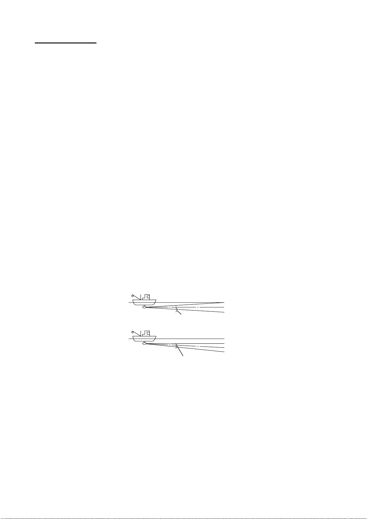
2. HORIZONTAL MODE
Sea surface reflections
To reduce sea surface reflections, set the tilt angle to 5° or lower, so the upper edge of the
sonar beam does not hit the sea surface, or adjust TVG. When a decreased tilt angle is
used, sea surface reflections cover a large area as illustrated below.
Sea surface
8
°
Sea surface
8
°
Tilt angle
indication
Sea surface
reflections
Sea surface reflections
Wake
A wake produced by own ship or another ship can be a strong reflecting object when a
decreased tilt angle is used. As the wake appears as a thick continuous line, it can be
easily distinguished from a fish school. A wake contains many air bubbles which attenuate
ultrasonic energy, making it difficult to sound beyond the wake.
Other
ship
Own
ship
Own ship's
screw noise
Wake produced
by other ship
Wake
Own ship's
screw noise
Own ship's wake
(produced when
own ship turned)
2-28
Page 49

2. HORIZONTAL MODE
Sidelobe echo (false echo)
An ultrasonic wave is emitted in the direction set by the [TILT] control (main beam),
however there are some emissions outside the main beam. These are called sidelobes.
The energy of the sidelobe is fairly weak but when the water is comparatively shallow and
the bottom is rocky and hard, strong signals are detected by the sidelobe. These are
represented on the display as a false echo as shown below.
Mainlobe echo
Sidelobe
Mainlobe
Sidelobe echo
The bottom echo
detected by sidelobe
appears at a certain
tilt angle when the
sidelobe points vertically. Also, poor
soundome projection
may result in a similar
false echo.
Sidelobe echoes
Noise and interference
When the fishing ground is crowded with many fishing boats, the sonar is subject to
interference from ultrasonic equipment (echo sounder or sonar) on other boats as well as
those on own ship.
For instance, interference from the sonar on other boats will show itself on the display as
in (A) in the figure below. This interference can be suppressed by changing the Tx rate on
the COM1 menu. Noise from marine life shows itself on the displays as in (B) in the figure
below. This type of noise can be suppressed with the interference rejector on the COM1
menu.
(A) Inteference from (B) Interference from
other sonars (yours marine life
or other's)
Noise and interference
2-29
Page 50

2. HORIZONTAL MODE
2.14.3 Combination display examples
Horizontal/history display
Press the
Own ship
marker
Train
position
Cursor
key to displ ay the horizontal /history display.
Tilt angle
Cursor position data
→17
↓ 14
B148°
+
Range
R 40 m
T 40°
Tilt angle indicator
30
25
34° 12. 343' N
134° 34. 213' W
CSE 357° SPD 9.9 kt
Interference rej. ON
Target lock indicator
Transducer status
indicator
Position in latitude
and longitude*
Course*, speed*
Fish echo
Bottom echo
* Requires appropriate
sensor input.
Horizontal Display
(main window)
History Display
(sub window)
Horizontal/history display
The hori z ontal display appears in the main window; the history display in the sub window.
The length of the picture displayed in the histor y display is equal to about four full-circle
pictures. Thus the hist or y display lets you obs er ve the history of fish movement and
distribution. It is also us eful for detecting bottom fish, reefs and s unk en vessels.
Note that the history display cannot be adjusted.
2-30
Page 51

Horizontal/video plotter display
2. HORIZONTAL MODE
Press the
Own ship
marker
Train
position
Track*
Event marker
Cursor
key to display the horizontal/video plotter displa y.
Tilt angle
Cursor position data
→18
↓ 15
B154
°
+
Range
R 40 m
T 40
°
34° 12. 343' N
134° 34. 213' W
Tilt angle indicator
25
CSE 357° SPD 9.9 kt
30
Interference rej. ON
Target lock indicator
Transducer status
indicator
Position in latitude
and longitude*
Course*, speed*
Sonar range marker
(Radius changes with
video plotter range.)
Event marker
(Entered from
horizontal mode)
→15
B 195
°
Event marker data
* Requires appropriate
sensor.
Horizontal Display
(main window)
Track*
Video Plotter Display
(sub window)
500
Scale
Horizontal/Video Plotter display
The horizontal display appears in the main window; the video plotter display, which mainly
traces ship’s track, in the sub window. Compared to the horizontal display the video
plotter ’s range is much longer. For example, an event marker entered on the horizontal
display disappears from that display when it goes out of the current range. However, it
remains on the video plotter display f or a much longer time when a long range scale is
used. This can be useful when you want to return to the location marked with an event
marker. To show track on the horizontal display the tilt angle must be less than 75
degrees.
You may switch control between the hor izontal display and the video plott er display with
the [MAIN/SUB] key. The message MAIN W INDOW CONTROLLABLE or SUB WINDOW
CONTROLLABLE appears with each pressing of the key. A red rectangle circumscribes
the sub window when it is selected. With the video plott er display selected you may
change its range with the [RANGE] control.
Note: Controls other than RANGE may only be operated fr om the main window. When
you attempt to operate them when the sub window is selected the message
SELECT MAIN WINDOW appears.
2-31
Page 52

2. HORIZONTAL MODE
Horizontal/strata display
Press the
Own ship
marker
Train
position
Color bar
for strata
display
Cursor
key to displ ay the horizontal /strata display.
Tilt angle
Cursor position data
→12
↓ 10
B133°
+
Range
R 40 m
T 40°
CSE 357° SPD 9.9 kt
Tilt angle indicator
30
25
34° 12. 343' N
134° 34. 213' W
PORT STBD
Interference rej. ON
Target lock indicator
Transducer status
indicator
Position in latitude
and longitude*
Course*, speed*
Number of lines increases
by one with each train.
Top line is latest; bottom
line is oldest.
* Requires appropriate
sensor input.
-90°
Horizontal Display
(main window)
0° +90°
Heading
Strata Display
(sub window)
Horizontal/Strata display
The hori z ontal display appears in the main window; the strata display in the sub wi ndow.
The str ata picture show s bottom undulations in different colors. This is useful in bottom
trawli ng for avoiding obstructions which may damage the net.
Coverage for the horizont al mode is 360° pictur e, and for the strat a display it is maxi m um
90° from port to 90° starboard.
The str ata display may be adjus ted with the [RANGE] and [SECTOR] controls. Press the
[MAI N/SUB] key to choose the mai n or s ub window. The mes sage MAIN WINDOW
CONTRO LLA B LE or S UB WINDOW CONTROLLABLE appears with each pressing of the
key. A r ed r ec tangle circums cr ibes the sub window when it can be controlled.
2-32
Page 53

2. HORIZONTAL MODE
◆
Color bar for the strata display
The depth of the bottom each in all dir ect ions is displayed in the sub window, in the
colors set by the color bar for the strata display. The color bar for the strata display
shows search angle range below 336 degrees.
Strongest
color
Color bar for
strata display
Weakest
color
12
-12
-90
˚
-18
The undulation of the bottom echo in all directions
is shown by the colors on the color bar for the
strata display.
˚
0
˚
-6
˚
˚
˚
18
6
˚
˚
90
˚
The position of the weakest echo can be changed with the [RANGE] control, and the
width of each color on the color bar for the strata display with the [SECTOR] control. 25
and 13 steps are available, respectively.
Use the [SECTOR] control to
adjust width of each color.
Weakest color
Use the [RANGE] control to move
the location of the weakest echo color.
Note: TILT, TRAIN, FULL/HALF, FAST SCAN, R/B, EVENT, TARGET, CUSTOM
MODE controls may only be operated from the main window. When you
attempt to operate them fr om the sub window the message “SELECT MAIN
WINDOW.” appears for about four seconds.
◆
Flat bottom and strata display
Each layer on the strata
display is equal to one
train on the horizontal
display.
Color "a"
The color of this position
on the color bar is the
color of point "a" on the
strata display.
-90˚
PORT STBD
+90˚
Color "a"
on the color bar
When the bottom is flat
the horizontal display
inscribes the bottom as a
true circle, and the strata
display inscribes the color
of point "a".
Flat bottom and strata display
2-33
Page 54

2. HORIZONTAL MODE
◆
Projection in fore direction and strata display
Color "b" on the color bar
is displayed here.
+90˚
Color "b"
Color
"a"
-90˚
PORT STBD
Projection in fore direction and strata display
◆
Depth gradually becoming shallower in fore direction and strata display
Color "b"
Color "b"
Color "d"
-90˚
Color "c"
PORT STBD
Color "a" on
the color bar
+90˚
Color "a"
Color "a"
Color "a"
Color "c"
Depth gradually becoming shallower in fore dire ction and strata display
◆
Depth gradually becoming deep er in fore direction and strata display
b
-90˚
Color "b"
Color "d"
Color "a"
Color "c"
cc
Depth gradually becoming deeper in fore direct ion and strata display
Color "a"ad
b
+90˚
2-34
Page 55

3. VERTICAL SCAN MODE
3.1 Operational Overview
The figure below shows the typical vertical scan m ode oper ating sequence.
6.
1.
Turn on the power.
POWER
7(a).
9.
Adjust gain.
XDR
Set center bearing of train
sector.
Set scanning sector.
GAIN
SECTOR TRAIN
DISPLAYMODE
5.
Set range.
MAIN
SUB
RANGE
FULL
HALF
CUSTOM MODE
8.
Set tilt angle.
TILT
FAST
SCAN
BRILL
11.
(ex. TVG) as required.
TARGET
MENU
R/B
EVENT
Adjust menu settings
2.
Lower the transducer.
4.
Select appropriate
vertical scan mode.
7(b).
Select training sector 180˚.
Control unit
10.
Measure range and
bearing to target with cursor.
3.
Adjust screen
brilliance.
3-1
Page 56

3. VERTICAL SCAN MODE
3.2 Displaying Vertical Scan Mode Display
3.2.1 Typical vertical scan mode display
Press the key to show the vert ical scan mode display.
Bearing indicator
(Shows training direction.)
FORE
Own
ship
PORT
STARBOARD
Bow
Cursor
position
data
Fish echo
Cursor
Horizontal
range
Bottom
echo
Depth
Range
marker
AFT
Interference
rejector ON
+→6
↓ 145
60
Training indicator
(Trained at 190
FORE AFT
°)
Heading*
340
24
63
°
Vertical range
Horizontal range
R → 60 m
↓ 100 m
60
34° 12. 343' N
134° 34. 213' W
100
Transducer status indicator
Filled arrow: Respective action completed
Blinking arrow: Action in progress
Horizontal range scale
Position in latitude
and longitude*
CSE 357
SPD 9.9 kt
DEP
TMP
CUR 11.0°
2.0 kt
GAIN 5.3
TVG LEVEL 4.0
DISTANCE 200 m
COLOR
35 m
12.3°C
°
Course*, speed*
Depth
Water temperature*
Tide direction*,
tide speed*
Gain setting
TVG level,
distance settings
Color bar
* Requires appropriate
Sector center
indicator
Sweep indicator
(Shows tilt angle
in vertical scan mode.)
Event marker
Vertical range scale
Horizontal range marker
sensor.
Typical vert ical scan mode display
3-2
Page 57

3. VERTICAL SCAN MODE
3.2.2 How the vertical scan picture is painted
The sounding beam is emitted and the information (target echoes) obtained by the
reflected echo appears in the corresponding sector as it appears on the horizontal mode.
The difference is that the training is performed only in vertical direction. It forms a
sounding area of a half-circle (like a slice of watermelon) to observe a vertical section of
underwater conditions.
Note: The tilt mechanism has a 90° range of movement. To paint the full 180° area,
therefore, the transducer is first trained through the left half (90-180°) of the area
followed by the right half (0-90°). Approximately two seconds are required to rotate
the transducer in the opposite direction before it begins training through the right or
left half.
Sounding Beam Screen Display
(1) Bearing of the
sounding beam
0°
BOW
180°
Tilting direction
(2) Sector center
(3) Display area
Select the bearing of the sounding beam (1) by [TRAIN]
control, the sounding sector center (2) by the [TILT] control and the display area (3) by the [SECTOR] control.
How the vertical scan mode picture is painted
(1) Bearing of the
sounding beam
180°
(2) Sector center,
(3) Display area
0°
Sector center 90°.
Display range
24°.
3-3
Page 58

3. VERTICAL SCAN MODE
3.2.3 Horizontal/vertical scan display
Press the key to display the horizontal/vertical scan displ ay.
Tilt angle
Cursor position
data
Vertical scan
bearing cursor
Range
Tilt angle indicator
Own ship
marker
Train
position
Cursor
→17
↓ 14
B156
+
R 40 m
T 40
°
Horizontal Display
(main window)
°
25
34° 12. 343' N
134° 34. 213' W
CSE 357° SPD 9.9 KT
AFT FORE
Vertical Scan Display
30
(sub window)
100
Interference rejector
ON
Target lock indicator
Transducer status indicator
Position in latitude,
and longitude*
Course*, speed*
* Requires navigator.
Sweep indicator
(tilt angle)
Horizontal/vertic al s c an display
The si z e of t he vert ical scan and horizontal displays and the location of the vertical scan
display may be changed as desired. Press the
key to change the ar r angement as in
the figure below .
3-4
Page 59

3. VERTICAL SCAN MODE
The displays are independent of each other so you can adjust them as desired. Press the
[MAIN/SUB] key to choose the window to adjust. Each press of the key momentarily
displays MAIN WINDOW CONTROLLABLE or SUB WINDOW CONTROLLABLE at the
top of the screen to let you know which window may be adjusted. A red rectangle
circumscribes the sub window when it is selected. The following controls are operative
from either window: SECTOR, TRAIN, RANGE, TILT, FAST SCAN, FULL/HALF and
CUSTOM MODE.
Note: R/B, EVENT or TARGET controls may only be operated from the main window.
When you attempt to operate them when the sub window is selected the message
SELECT MAIN WINDOW appears.
TRAIN control
For horizontal display: Sets training center direction.
For vertical scan display: Sets direction of bearing cursor shown on the horizontal mode
display.
SECTOR control
For the vertical scan display: When the display sector is 6° (minimum), the tilt angle of
the horizontal and vertical scan modes are interlocked and each transmission on the
horizontal display is reflected on the vertical scan display. The message TILT ANGLE
MONITOR WINDOW momentarily appears on the screen and the vertical bearing cursor
disappears.
Note: Only the [SECTOR] control may be operated in this condition.
.
3-5
Page 60

3. VERTICAL SCAN MODE
3.3 Choosing the Range
The [RANGE] control chooses the detection (display) range, in 15 settings. Choose the
range according to either the fish species being searched or the depth desired. Each time
the control is operated the newly chosen range briefly appears in large characters at the
screen top. Range is permanently displayed at the top right-hand corner of the screen.
Default vertical scan mode range settings
Unit 1 2 3 4 5 6 7 8 9 10 11 12 13 14 15
Meters 10 20 30 40 60 80 100 120 160 200 250 300 400 500 600
Feet 30 60 90 120 150 200 250 300 400 500 600 800 1000 1500 2000
Note 1: Unit of range measurement may be chosen from among meters, feet, fathoms,
passi/braza and Hiro (Japanese) with UNIT on the SYSTEM SETTING 1 menu.
For further details, see UNIT in paragraph 5.4.2.
Note 2: Ranges may be freely preset as desired. For further details, see paragraph 5.4.5.
3.4 Choosing Train Center
The [TRAIN] control determines the bearing of the vertical scan beam, from 0° to 180°.
Bearing of beam position can be found by observing the train indicator.
0° (360°) → 6° → 12° → 18° → ... 180°
Train Indicator Train of Vertical Scan Beam
Train indicator
TRAIN
Bow
Train indicator
Train 0° Train 90° Train 180°
FORE
STBD
Train indicator and display
AFT
3-6
Page 61

3. VERTICAL SCAN MODE
3.5 Choosing Display Sector
Sector means the width of the transducer training, from 6° to 180°.
24
°
Sector (Shown: 24°)
Sector
The [SECTOR] control chooses the training area among the sixteen positions shown in
the table below. Clockwise rotation of the control increases the sector width;
counterclockwise rotation decreases it.
1 2 3 4 5 6 7 8 9 10 11 12 13 14 15 16
Sector
width
6 12 24 36 48 60 72 84 96 108 120 132 144 156 168 180
(°)
One-touch selection of 180°°°°
1. Press the [FULL/HALF] key. A half-circle display of 180°
sector
is presented, and “FULL”
momentarily appears at the top of the display.
2. Press the [FULL/HALF] key again, and a 120°-sector display is presented, and
120° momentarily appears at the top of the display.
Note: Operating the [SECTOR] control after step 1 in the procedure above will display the
180°
sector at the next pressing of the [FULL/HALF] key.
Sector set with
SECTOR control
24
°
FULL/HALF
key
180
Half circle
°
180
FULL/HALF
0
°
key
°
180
°
120
0
°
°
How the FULL/HALF key works
3-7
Page 62

3. VERTICAL SCAN MODE
3.6 Choosing Sector Center
The center direction of the sounding beam in the vertical direction can be changed with
the [TILT] control. The setting range is 0° to 180° in increments of 6°. Choose the setting
which places the sector center in the middle of the detection range.
Sector center angle
set with TILT control
PORT
Sector of 48° set with
[SECTOR] control
STBD
Sector center
indicator
Automatic shifting of own ship position
In the example display at left, the sector
center indicator is starboard, and the
width of the sector is 48°.
Sector
range
180
°
0
Sector center
°
Own ship position on the screen is automatically shifted either rightward or leftward
according to the direction of the sector center and display sector width.
The figure below shows the own ship position has been shifted rightward on the screen to
provide the wider view at the port side.
Sector center 0° to 60
Sector center 66° to 114
Sector center 120° to 180
Display sector
Sector center
°: Own ship position shifted to port side
°: Own ship position shifted to center
°: Own ship position shifted starboard
How automatic shifting works
3-8
Page 63

3. VERTICAL SCAN MODE
3.7 Choosing the Tilt Speed
The [FAST SCAN] key chooses the tilt speed; that is, the stepping angle at which the
transducer scans. Two choices are available, 3° (normal speed) and 6° (high speed). Each
time the key is pressed the display momentarily shows “NORM” (normal speed) or “FAST”
(high speed).
Normal: 60 transmissions to complete a half circle, in increments of 3°.
High: 30 transm issions t o com plet e a half circle, in increments of 6°.
The time required to scan one full area of 180° depends on range used and other factors.
The table below shows the time required to complet e one f ull area on each range.
Ranges 1 2 3 4 5 6 7 8 9 10 11 12 13 14 15
Unit ft 30 60 90 120 150 200 250 300 400 500 600 800 1000 1500 2000
Time
required
(sec) for
one full
180
area
Unit m 10 20 30 40 60 80 100 120 160 200 250 300 400 500 600
Time
required
(sec) for
one full
180
area
Norm 13 13 13 13 13 13 13 13 15 17 20 26 31 46 60
Fast 9 9 9 9 9 9 9 9 9 10 11 14 17 24 31
°
Norm 13 13 13 13 13 13 13 14 18 22 27 31 41 50 59
Fast 9 9 9 9 9 9 9 9 10 12 15 17 22 27 31
°
Note: Values shown are f or reference purpose s . Actual values m ay vary.
3.8 Finding Echo Position with the Cursor
The cursor measures horizontal range and depth. O perate the Omnipad to place the
cursor where desired. Cursor data appears at the top left-hand corner on the screen.
Cursor data
+→ : Horizontal range
↓: Depth
NAV
DATA
Cursor
Location of cursor position data
3-9
Page 64

3. VERTICAL SCAN MODE
3.9 Event Marker
3.9.1 Entering an event marker
The event marker functions to mark important locations on the screen, and five may be
inscribed. Each time the [EVENT] key is pressed the “latest event marker” (
at the cursor location and all previously entered event markers are shown by the “previous
event marker” (+). When the capacity for event markers is reached, the eldest event
marker is erased from the screen to make room for the latest.
Note 1: The latitude and longitude position of the event marker can be output to a video
plotter and that position inscribed on the plotter’s screen with the external
waypoint mark (X). Each press of the [EVENT] key outputs event marker position.
For further details, see TARGET L/L in paragraph 5.4.2.
Note 2: Event markers cannot be inscribed in the vertical scan display when it is in the
sub window (Horizontal/vertical scan display). Inscribe the marker on the
horizontal display to show it in the vertical scan display.
⊕) is inscribed
1. Operate the Omnipad to place the cursor on the location desired for an event marker.
2. Press the [EVENT] key to inscribe the event marker. The event marker is inscribed on
the vertical scan display, as well as the horizontal and video plotter displays.
"Previous event
marker"
"Latest event marker"
Display area
NAV
DATA
To delete all event markers,
place cursor outside
display area and press the
[MENU] key.
3-10
How to inscribe and delete the event markers
Page 65

3. VERTICAL SCAN MODE
3.9.2 Deleting all event markers
All event markers can be erased from the screen as follows:
1. Operate the Omnipad to place the cursor outside the display area.
2. Press the [EVENT] key to show the following dialog box. Do the next step within four
seconds; otherwise the dialog box will be erased.
DELETE EVENT MARK?
NO YES
3. Press ► to choose YES and then press the [MENU] key. All event markers are erased
from the screen.
3.10 Depth and Horizontal Range Markers
The depth and horizontal range markers function to measure the horizontal range and
depth to a desired echo.
Note: Depth and horizontal range markers cannot be inscribed on the vertical scan
display when it is in the sub window (Horizontal/vertical scan display). Inscribe the
markers on the horizontal display to show them in the vertical scan display.
1. Operate the Omnipad to place the cursor on the location desired.
2. Press the [R/B] key to display the depth and horizontal range markers. Horizontal
range and depth appear on the screen.
3. To erase the depth and horizontal range markers, place the cursor on the intersecting
point of the depth and horizontal range markers or outside the display and then press
the [R/B] key.
Horizontal range
Horizontal range
105
Depth marker
94
NAV
DATA
Depth
marker
Depth and horizontal range markers
3-11
Page 66

3. VERTICAL SCAN MODE
3.11 Adjusting the Picture
3.11.1 Displaying weak echoes clearly
Echoes from targets (such as the bottom or a fish) return to the transducer in order of the
distance to them, and when their intensities are compared at the transducer face, those
from nearer targets are generally stronger when their reflecting properties are nearly equal.
The sonar operator will be quite inconvenienced if these echoes are directly displayed on
the screen, since he won’t be able to judge the actual size of the target from the size of
echoes displayed on the screen. To overcome this inconvenience, use the TVG function. It
compensates for propagation loss of sound in water: amplification of echoes on short
range is suppressed and gradually increased as range increases, so that similar targets
are displayed in similar intensities irrespective of the ranges to them.
The TVG also functions to suppress unwanted echoes and noise which appear in a certain
range area on the screen.
To adjust TVG:
1. Press the [MENU] key to open the menu.
2. Press ▲ to choose MENU and then press ◄ or ► to choose the VERT menu.
MENU
TVG LEVEL 4.0
TVG DISTANCE 4.0
GAIN ADJUST 0
RES. COLOR LO G
CLUTTER 0
HORZ RANGE x1
: SELECT
COM1 VERT ES PRESET SY SCOM2 HORZ
: CHANGE MENU: END
VERT menu
3. Press ▲ or ▼ to choose TVG DISTANCE and then press ► to show the following
dialog box.
3-12
TVG DISTANCE
GAIN
Hi
Lo
200m
4.0
Page 67

3. VERTICAL SCAN MODE
4. Press ◄ or ► to adjust TVG distance, considering sea conditions. The larger the figure
the greater the distance at which the TVG works.
TVG
. . . .
. . . .
10.0
1000
3280
600
550
Distance
Setting
Meters 3 8 20 40 60 100 130 160 200 250 320
Feet 10 30 70 130 210 330 410 520 660 820 1040
Passi/braza 2 5 10 20 40 60 80 100 120 150 180
Fathoms
0 0.5 1.0 1.5 2.0 2.5 3.0 3.5 4.0 4.5 5.0
5 10 20 40 60 80 100 110 140 170
2
5. Press ▲ or ▼ to close the dialog box and return to the VERT menu.
6. To suppress reflections from the sea surface or plankton, choose TVG LEVEL and then
press ►.
7. Press ◄ or ► to adjust TVG LEVEL, considering sea conditions. The larger the figure
the less the gain over distance.
8. Press the [MENU] key to register your selection and close the menu.
Wrong Correct Level too high Distance too high
Examples of proper and improper TVG
3-13
Page 68

3. VERTICAL SCAN MODE
3.11.2 Suppressing noise and interference
You may encounter occasional or intermittent noise and interference as shown below. This
is mostly caused by electrical equipment, engine, propeller noise from own ship, or noise
from other sonars being operated nearby. If interference appears, turn on the interference
rejector as below to suppress it.
Interference rejector ON
Interference
(In this display,
interference shows
itself every 6°.)
Appearance of interference
1. Press the [MENU] key to open the menu.
2. Press ▲ to choose MENU at the top of the screen.
3. Press ◄ or ► to choose the COM1 menu.
4. Press ▲ or ▼ to choose INT REJECT.
5. Press ► to open the dialog box.
6. Press ◄ or ► to choose OFF or ON as appropriate.
7. Press the [MENU] key to register your selection and close the menu.
3.11.3 Gain adjustment
Adjust the gain here when there is disparity in gain level between the main and sub
windows.
1. Press the [MENU] key to open the menu.
2. Press ▲ to choose MENU at the top of the screen.
3. Press ◄ or ► to choose the VERT menu.
4. Press ▲ or ▼ to choose GAIN ADJUST.
5. Press ► to open the dialog box.
6. Press ◄ or ► to adjust.
7. Press the [MENU] key to register your selection and close the menu.
3-14
Page 69

3. VERTICAL SCAN MODE
3.11.4 Resolution color
RES. COLOR sets transfer characteristics of input signal level versus display echo level.
Echo strength is emphasized in order of CUBE, SQUARE, LINEAR, LOG. You can see the
characteristics of each by watching the color bar as you change the setting.
1. Press the [MENU] key to open the menu.
2. Press ▲ to choose MENU at the top of the screen.
3. Press ◄ or ► to choose the VERT menu.
4. Press ▲ or ▼ to choose RES. COLOR.
5. Press ► to open the dialog box.
6. Press ◄ or ► to choose appropriate option, referring to the description below.
LOG: Displays weak to strong echoes in their respective levels. This setting is
suitable for general use.
LINEAR: Downplays the weak echoes when compared with LOG. Effective for
suppressing weak echoes such as plankton.
SQUARE: Strong echoes are emphasized more than in LINEAR.
CUBE: Strong echoes are emphasized even more than in SQUARE.
7. Press the [MENU] key to register your selection and close the menu.
3.11.5 Suppressing clutter
Low intensity echoes, often caused by sediments in water, are painted on the screen as a
large number or random dots. This noise can be suppressed.
1. Press the [MENU] key to open the menu.
2. Press ▲ to choose MENU at the top of the screen.
3. Press ◄ or ► to choose the VERT menu.
4. Press ▲ or ▼ to choose CLUTTER.
5. Press ► to open the dialog box.
6. Press ◄ or ► to choose 0, 1, 2 or 3 as appropriate. The higher the number (setting)
the weaker the echoes which are erased.
7. Press the [MENU] key to register your selection and close the menu.
3-15
Page 70

3. VERTICAL SCAN MODE
3.11.6 Choosing horizontal range expansion factor
You may choose the horizontal range expansion factor for the vertical scan picture, from
x1 or x2. Note that this feature cannot be adjusted when the vertical search mode,
activated by a function key, is turned on.
1. Press the [MENU] key to open the menu.
2. Press ▲ to choose MENU at the top of the screen.
3. Press ◄ or ► to choose the VERT menu.
4. Press ▲ or ▼ to choose HORZ RANGE.
5. Press ► to open the dialog box.
6. Press ◄ or ► to choose x1 or x2 as appropriate.
7. Press the [MENU] key to register your selection and close the menu.
3-16
Page 71

3. VERTICAL SCAN MODE
3.12 Interpreting the Vertical Scan Display
This section provides information necessary for interpreting the vertical scan display.
3.12.1 Sample echo displays
Port-starboard picture
You can see fish echoes at the center-right of the screen. The bottom is displayed wider
as the distance from the ship’s position increases. Therefore, it may be difficult to
discriminate bottom fish.
Own ship
PORT
Bottom
STBD
Fish
school
Port-starboard picture
When ship passes over fish schools
The sounding beam is directed fore-aft and the display is off-centered* to present a wider
view of the area forward of the ship. You can clearly see fish schools approaching from the
bow of the ship.
*: Automatically off-centered.
Forward
Own ship
FORE
Fish
school
FORE
Fish
school
AFT
AFT
Picture appearance when passing over fish schools
3-17
Page 72

3. VERTICAL SCAN MODE
Display of net hauling
This is an example of net hauling display. The location of the net is indicated clearly.
FORE
Net
AFT
Net hauling and sonar picture
False echo
In shallow water (depth less than 100 m) detection, unwanted echoes as shown in the
figure below may appear. This phenomenon is caused by the false echo from the previous
transmission. Reducing the Tx rate on the COM1 menu may lessen this effect.
PORT STBD
False echo
Bottom
Fish
Range
False echoes
3-18
Page 73

4. ECHO SOUNDER MODE
4.1 Operational Overview
The figure below shows the typical echo sounder mode operating s equenc e.
8.
Set tilt angle.
7.
1.
Turn on the power.
POWER
Select display sector.
6.
Adjust gain.
XDR
GAIN
SECTOR TRAIN
5.
Set range
MAIN
SUB
RANGE
FULL
HALF
.
11.
Adjust menu settings
(turn on A-scope
display, etc.).
TILT
FAST
BRILL
TARGET
SCAN
MENU
2.
Lower the transducer.
DISPLAYMODE
4.
Select echo sounder
mode.
9.
Set picture advance speed.
Control unit
CUSTOM MODE
R/B
EVENT
10.
Measure range to fish
school with cursor.
3.
Adjust screen
brilliance.
4-1
Page 74

4. ECHO S OUNDER MODE
4.2 Typical Echo Sounder Display
Press the key to display the echo sounder picture.
Interference
rejector ON
Cursor
position
Minute marker
Fish echo
Cursor
Range
Bottom echo
+ 4
↓
DEP
6.5 m
Bearing
indicator
(Shows train
direction.)
5
Tilt angle indicator
(Shows tilt angle of transducer.)
Tilt angle
Heading
340°
TMP
Range
R 10 m
T 60°
34° 12. 343' N
134° 34. 213' W
5
10
12. 3˚C
Transducer status indication
Position in latitude*,
longitude*
CSE 357˚
SPD 9.9 kt
CUR 11.0˚
2.0 kt
GAIN 5.3
TVG LEVEL 4.0
DISTANCE 200 m
Course*, speed*
Tide direction*,
tide speed*
Gain setting
TVG level,
distance settings
Color bar
* Requires appropriate
sensor.
Depth
(When the tilt angle
is 90 deg., the depth
measured by this
sonar is displayed
inside a rectangle.)
Typical echo soun der display
Water
temperature*
Event marker
Range marker
Range scale
4-2
Page 75

4. ECHO SOUNDER MODE
4.3 Choosing the Range
The [RANGE] control chooses the detection (display) range, in 15 settings. Choose the
range according to either the fish species being searched or the depth desired. Each time
the control is operated the newly chosen range briefly appears in large characters at the
screen top. Range is permanently displayed at the top right-hand corner.
Normally the range is set so that the bottom is traced at the lower part of the screen.
Surface
RANGE m
Bottom
Range concept
Default echo sounder mode range settings
Unit 1 2 3 4 5 6 7 8 9 10 11 12 13 14 15
Meters 10 20 30 40 60 80 100 120 160 200 250 300 400 500 600
Feet 30 60 90 120 150 200 250 300 400 500 600 800 1000 1500 2000
Note 1: Unit of range measurement may be chosen from among meters, feet, fathoms,
passi/braza and Hiro (Japanese). For further details, see UNIT in paragraph 5.4.2.
Note 2: Ranges may be freely preset as desired. For further details, see paragraph 5.4.6.
4-3
Page 76

4. ECHO SOUNDER MODE
4.4 Train Direction
The sounding beam may be directed 360° in any direction. Operate the [TRAIN] control to
choose sounding beam direction. Each setting on the control is an increment of 6°. The
train indicator at the top of the screen shows training direction: 0°, fore direction; 90°,
starboard direction; 180°, aft direction, and 270°, port direction.
0° (360°) → 6° → 12° → 18° → ... 354°
Train 0° Train 90° Train 180° Train 270°
Train indicator and display
4.5 Choosing Tilt Angle
The transducer can be pointed directly toward the bottom or forward of the ship. Operate
the [TILT] control to choose an appropriate tilt angle. The available tilt angle is 0° (horizontal
direction) to 90° (vertical), in increments of 1°
display to the right of “T”.
. Chosen tilt angle appears at the top of the
4.6 Choosing Picture Advance Speed
The picture advance speed determines how quickly the vertical scan lines run across the
screen, from right to left. When choosing a picture speed, keep in mind that a fast advance
speed will expand a fish school horizontally on the screen and a slow one will contract it.
1. Press the [FAST SCAN] key. The following dialog box appears. Do the next step within
four seconds; otherwise the dialog box will be erased.
ADVANCE
1/8 1/4 1/2 1/1 2/1
2. Press ◄ or ► ([FAST SCAN] key may also be used) to choose a speed. The fractions
in the dialog box correspond to the number of scan lines produced per transmission. For
example, “2/1” means two scan lines are produced per transmission.
3. Press the [MENU] key to close the dialog box. Note that the dialog box is automatically
closed if there is no control operation for about four seconds.
4-4
Page 77

4. ECHO SOUNDER MODE
4.7 Measuring Range by Cursor
Use the cursor to display the range from own ship to the cursor location. Use the Omnipad
to place the cursor where desired. The range to the cursor appears at the upper left-hand
corner of the screen.
Range to cursor
: Range
↓
NAV
D ATA
or
A-SCOPE
DISPLAY
Depth, Water Temp. Display
Cursor
How to measure range with the cursor
4.8 Event Marker
The event marker functions to mark important locations on the screen, and five may be
inscribed. Each time the [EVENT] key is pressed the “latest event marker” (
the cursor location and all previously entered event markers are shown by the “previous
event marker” (+). When the capacity for event markers is reached, the eldest event marker
is erased from the screen to make room for the latest.
Note 1: The event marker inscribed on the echo sounder display will also be inscribed on
the horizontal and video plotter displays. However, the marker is always inscribed
at own ship position on the horizontal and video plotter displays regardless of the
location of the marker on the echo sounder display.
Note 2: The latitude and longitude position of the event marker can be output to a video
plotter and that position inscribed on the plotter’s screen with the external waypoint
mark (X). Each press of the [EVENT] key outputs event marker position. For further
details, see TARGET L/L in paragraph 5.4.2.
⊕) is inscribed at
Note 3: Event markers are automatically erased as they move off the screen with picture
advancement. However, event marks entered from the echo sounder remain on the
horizontal and video plotter displays, until they are erased.
4-5
Page 78

4. ECHO SOUNDER MODE
4.8.1 Inscribing the event marker
1. Operate the Omnipad to place the cursor on the location desired for an event marker.
2. Press the [EVENT] key to inscribe the event marker.
Display area
"Previous event marker"
NAV
D ATA
or
A-SCOPE
DISPLAY
Depth, Water Temp. Display
"Latest event marker"
To delete all event markers,
place the cursor outside
the display area and
press the [EVENT] key.
How to inscribe and delete the event markers
4.8.2 Deleting all event markers
All event markers can be erased from the screen as follows:
1. Operate the Omnipad to place the cursor outside the display area.
2. Press the [EVENT] key to show the following dialog box. Do the next step within four
seconds; otherwise the dialog box will be erased.
DELETE EVENT MARK?
NO YES
3. Press ► to choose YES and then press the [MENU] key. All event markers are erased
from the screen.
4-6
Page 79

4. ECHO SOUNDER MODE
4.9 Range Marker
The range marker functions to measure the range to a target echo (fish school, bottom,
etc.)
1. Operate the Omnipad to place the cursor on the location desired.
2. Press the [R/B] key to display the range marker. The range marker appears along with
range indication.
3. To erase the range marker, place the cursor on the marker or outside the display area
and then press the [R/B] key.
Range marker
NAV
Range
67
Depth, Water Temp. Display
D ATA
or
A-SCOPE
DISPLAY
Range marker
4-7
Page 80

4. ECHO SOUNDER MODE
4.10 Adjusting the Picture
4.10.1 Displaying weak echoes clearly
Echoes from targets (such as the bottom or a fish) return to the transducer in order of the
distance to them, and when their intensities are compared at the transducer face, those
from nearer targets are generally stronger when their reflecting properties are nearly equal.
The sonar operator will be quite inconvenienced if these echoes are directly displayed on
the screen, since he won’t be able to judge the actual size of the target from the size of
echoes displayed on the screen. To overcome this inconvenience, use the TVG function. It
compensates for propagation loss of sound in water: amplification of echoes on short range
is suppressed and gradually increased as range increases, so that similar targets are
displayed in similar intensities irrespective of the ranges to them.
The TVG also functions to suppress unwanted echoes and noise which appear in a certain
range area on the screen.
To adjust TVG:
1. Press the [MENU] key to open the menu.
2. Press ▲ to choose MENU and then press ◄ or ► to choose the ES menu.
MENU
TVG LEVEL
TVG DISTANCE
GAIN ADJUST 0
RES. COLOR LOG
CLUTTER 0
A-SCOPE OFF
: SELECT
COM1 HORZ VERT ES PRESET SY SCOM2
4.0
4.0
: CHANGE
MENU: END
ES menu
4-8
Page 81

4. ECHO SOUNDER MODE
3. Press ▲ or ▼ to choose TVG DISTANCE and then press ►. The following dialog box
appears.
GAIN
Hi
Lo
TVG DISTANCE
200 m
4.0
4. Press ◄ or ► to adjust TVG distance.
TVG
. . . .
. . . .
10.0
1000
3280
600
550
Distance
Setting
Meters 3 8 20 40 60 100 130 160 200 250 320
Feet 10 30 70 130 210 330 410 520 660 820 1040
Passi/braza 2 5 10 20 40 60 80 100 120 150 180
Fathoms
0 0.5 1.0 1.5 2.0 2.5 3.0 3.5 4.0 4.5 5.0
5 10 20 40 60 80 100 110 140 170
2
5. Press ▲ or ▼ to close the dialog box and return to the ES menu.
6. To suppress reflections from the sea surface or plankton, choose TVG LEVEL and then
press ►.
7. Press ◄ or ► to adjust TVG LEVEL.
8. Press the [MENU] key to register your selection and close the menu.
4-9
Page 82

4. ECHO SOUNDER MODE
4.10.2 Finding echo strength (A-scope display)
The A-scope display shows echoes at each transmission with amplitudes and tone
proportional to their intensities, on the right 1/4 of the screen. It is useful for estimating the
kind of fish school and bottom composition.
1. Press the [MENU] key.
2. Press ▲ to choose MENU.
3. Press ◄ or ► to choose ES.
4. Press ▼ to choose A-SCOPE.
5. Press ◄ or ► to open the dialog box.
A-SCOPE
OFF ON
6. Press ► to choose ON.
7. Press the [MENU] key to close the dialog box.
Echo sounder display
Depth, water temp. display
A-scope display
A-scope display
4-10
Page 83

4. ECHO SOUNDER MODE
4.10.3 Gain adjustment
Adjust the gain here when there is disparity in gain level between the main and sub
windows.
1. Press the [MENU] key to open the menu.
2. Press ▲ to choose MENU at the top of the screen.
3. Press ◄ or ► to choose the ES menu.
4. Press ▲ or ▼ to choose GAIN ADJUST.
5. Press ► to open the dialog box.
6. Press ◄ or ► to adjust.
7. Press the [MENU] key to register your selection and close the menu.
4.10.4 Resolution color
RES. COLOR sets transfer characteristics of input signal level versus display echo level.
Echo strength is emphasized in order of CUBE, SQUARE, LINEAR, LOG. You can see the
characteristics of each by watching the color bar as you change the setting.
1. Press the [MENU] key to open the menu.
2. Press ▲ to choose MENU at the top of the screen.
3. Press ◄ or ► to choose the ES menu.
4. Press ▲ or ▼ to choose RES. COLOR.
5. Press ► to open the dialog box.
6. Press ◄ or ► to choose appropriate option, referring to the description below.
LOG: Displays weak to strong echoes in their respective levels. This setting is
suitable for general use.
LINEAR: Downplays the weak echoes when compared with LOG. Effective for
suppressing weak echoes such as plankton.
SQUARE: Strong echoes are emphasized more than in LINEAR.
CUBE: Strong echoes are emphasized even more than in SQUARE.
7. Press the [MENU] key to register your selection and close the menu.
4-11
Page 84

4. ECHO SOUNDER MODE
4.10.5 Suppressing clutter
Low intensity echoes, often caused by sediments in water, are painted on the screen as a
large number or random dots. This noise can be suppressed.
1. Press the [MENU] key to open the menu.
2. Press ▲ to choose MENU at the top of the screen.
3. Press ◄ or ► to choose the ES menu.
4. Press ▲ or ▼ to choose CLUTTER.
5. Press ► to open the dialog box.
6. Press ◄ or ► to choose 0, 1, 2 or 3 as appropriate. The higher the number (setting) the
weaker the echoes which are erased.
7. Press the [MENU] key to register your selection and close the menu.
4-12
Page 85

5. MENU OPERATION
5.1 COM1 Menu
5.1.1 Displaying the COM1 menu
1. Press the [MENU] key to open the menu.
2. Press ▲ to choose MENU, and then press ◄ to choose COM1.
MENU
TX POWER MAX
PULSELENGTH LONG
TX RATE 10
INT REJECT OFF
AGC OFF
AUDIO LEVEL 0
: SELECT
COM1 HORZ VERT ES PRESET SYSCOM2
: CHANGE ME N U : END
COM1 menu
5.1.2 COM1 menu description
TX POWER: Chooses transmitter output power to maximum or minimum. For further
details, see paragraph 2.11.1.
PULSELENGTH: Chooses pulselength to short or long. For further details, see
paragraph 2.11.2.
TX RATE: The Tx rate may be set between 1-10 in the case of the internal transmitter, or
an external synchronous signal may be used. The higher the number the greater the
number of transmissions. For operation in shallow waters, choose the Tx rate which
displays the second reflection from the bottom between the sea surface and bottom. For
use of an external video sounder or sonar, choose EXT.
INT REJECT: Turns the interference rejector on or off. For further details, see paragraph
3.11.2.
AGC: Automatically lowers sensitivity against strong echoes (such as those from the
bottom and large fish schools) to emphasize weak echoes such as those from fish close
to the bottom.
AUDIO LEVEL: Adjust the volume of the optional speaker.
5-1
Page 86

5. MENU OPERATION
5.2 COM2 Menu
5.2.1 Displaying the COM2 menu
1. Press the [MENU] key to open the menu.
2. Press ▲ to choose MENU, and then press ◄ or ► to choose COM2.
MENU
DELETING TRACK NO
WHITE MARKER OFF
SIG LEVEL OFF
COLOR 16
BKGD COLOR 2
: SELECT
COM1 HORZ VERT ES PRESET SYSCOM2
: CHANGE ME N U : END
COM2 menu
5.2.2 COM2 menu description
DELETING TRACK: Choose ON to delete all ship’s track (from horizontal and
horizontal/video plotter displays).
WHITE MARKER: Displays desired echo in white. It is useful for discriminating bottom
fish from the bottom echo. The setting range for the 8-color display is OFF, 1-7, and for
the 16-color display, OFF, 1-15.
SIG LEVEL: Refer to page 2-17.
COLOR: Chooses 8- or 16-color display.
BKGD COLOR: Chooses color of background, text and menu. Three choices are
available and these are shown in the table below.
BKGD COLOR Background Text Menu
1 Black Gray Dark-blue
2 Dark-blue White Medium blue
3 White Black Gray
5-2
Page 87

5. MENU OPERATION
5.3 Short-cut Menu, Preset Menu
These menus program the CUSTOM MODE keys [1], [2] and [3]. The menu to use may
be chosen with CUSTOM KEY on the SYSTEM SETTING 1 menu.
Short-cut key: One-touch activation of the operator-selected dialog box.
Preset key: One-touch setup of mode, sector, train, range, tilt and scan speed. Below
are the default settings for PRESET.
Custom mode key default settings for PRESET
CUSTOM MODE key Display Mode Sector Train Range (m) Tilt Speed
Key 1
Key 2 Horizontal 360° 0° 160 30° Fast
Key 3 Vertical Scan 180° 90° 120 90° Fast
Horizontal
Expansion
240° 0° 160 30° Fast
5.3.1 Choosing short-cut or preset
1. Press the [MENU] key to open the menu.
2. Press ▲ to choose MENU, and then press ► to choose SYS.
MENU
GO TO SYS MENU
: SELECT
COM1 HORZ VERT ES PRESETCOM2
: CHANGE
NOYES
MENU: END
SYS
Display for opening system menu
3. Press ▼ to choose GO TO SYS MENU.
4. Press ◄ to choose YES.
5-3
Page 88

5. MENU OPERATION
** SYSTEM MENU **
SYSTEM SETTING:
RANGE-SONAR MODE
RANGE-VERTICAL MODE
RANGE-E/S MODE
RANGE-TRACK MODE
COLOR PALETTE
LANGUAGE
SYSTEM BACKUP
LOAD BACKUP DATA
HEADING OFFSET, DRAFT OFFSET
ADJ MOTION SENSOR
TX FREQ ADJUST
TEST
TEST PATTERN
DEMO MODE
DEFAULT
: SELECT
: MENU DISPLAY MENU: END
System menu
5. SYSTEM SETTING is highlighted; press ► to open the SYSTEM SETTING menu.
** SYSTEM SETTING 1 **
MENU 1 2
POSITION :
TRACK : OFF ON
CURRENT DATA :
HEADING INDICATION :
NORTH MARK :
CSE DATA :
NAV DATA :
TVG CORRECTION :
UNIT :
TEMP
TARGET L/L :
CUSTOM KEY :
EMPHASIS MODE :
ETA MARK :
SHIP'S L/L SHIP'S LOP CURSOR L/L
OFF FLOW FROM FLOW TO
TRUE AZ
OFF ON
NAV GYRO
GPS LoranC LoranA DR DECCA OTHERS
OFF 1/2 1/1
m ft fa HIRO P/B
: °C °F
OFF ON
PRESET KEY
OFF NORMAL RED
OFF 10sec 30sec 1min 3min 6min
SHORT-CUT KEY
: SELECT
: CHANGE MENU: END
System setting 1 menu
6. Press ▲ or ▼ to choose CUSTOM KEY.
7. Press ◄ or ► to choose PRESET KEY or SHORT-CUT KEY as desired.
8. Press the [MENU] key twice to register your selection and close the menu.
5-4
Page 89

5. MENU OPERATION
5.3.2 Changing setting of preset key
1. Choose PRESET KEY following the procedure in paragraph 5.3.1.
2. Press the [MENU] key to open the menu.
3. Press ▲ to choose MENU, and then press ◄ or ► to choose PRESET.
MENU
PRESENT
CUSTOM
CUSTOM2
CUSTOM3
ADJUST THE KNOBS AND FUNCTION KEYS TO THE DESIRED SETTING,
THEN PRESS A CUSTOM MODE KEY TO SAVE THE SETTING.
FUNCTION KEY: ENTRY MENU: END
1
COM1 HORZ VERT ES
MODE SECTOR TRAIN RANGE TILT SPEED
360
240
360
180
°
°
°
°
90
0
°
0
°
0
°
°
160
160
160
120
PRESET
30
°
30
°
30
°
90
°
SYSCOM2
NORM
FAST
FAST
FAST
PRESET menu
4. Set the [MODE], [SECTOR], [TRAIN], [RANGE], [TILT] and [FAST SCAN] controls
according to target fish or fishing area. Current setting is shown in the “PRESENT”
section.
5. Press the CUSTOM MODE keys [1], [2] or [3] as appropriate to program. You are
asked if you want to save the settings to the custom key pressed. (In the example
below the custom key [1] was pressed.)
SAVE THE SETTINGS TO CUSTOM1 KEY?
NO YES
: CHANGE MENU: END
6. Press ► to choose YES.
7. Press the [MENU] key. The message “PRGM SET” appears at the screen top.
8. Press the [MENU] key to finish.
Activating a custom mode key
1. Press appropriate CUSTOM MODE key. The indication CUSTOM1, CUSTOM2 or
CUSTOM3 appears at the top of the screen depending on key pressed.
2. To escape from the custom mode operation, operate any of the following controls:
[MODE], [SECTOR], [TRAIN], [RANGE], [TILT] or [FAST SCAN].
5-5
Page 90

5. MENU OPERATION
5.3.3 Changing setting of short-cut key
The default settings are key [1], vertical search; key [2], volume, and key [3], delete track.
The operator may change their functions as desired.
Note: In the combination modes the short-cut key may only be activated from the main
window.
1. Choose SHORT-CUT following the procedure in paragraph 5.3.1.
2. Press the [MENU] key to open the menu.
3. Press ▲ to choose MENU, and then press ◄ or ► to choose SHORT-CUT.
MENU
KEY 1
KEY 2
KEY 3
SELECT FUNCTION TO BE ALLOCATED TO EACH CUSTOM KEY.
CUSTOM KEY MAY BE USED AS A PRESET KEY.
: SELECT
COM1 HORZ VERT ES
VER SEARCH VOLUME DEL TRACK AUTO TILT BKGD
SIG LEVEL CLUTTER RES. COLOR WHITE MARKER
VER SEARCH VOLUME DEL TRACK AUTO TILT BKGD
SIG LEVEL CLUTTER RES. COLOR WHITE MARKER
VER SEARCH VOLUME DEL TRACK AUTO TILT BKGD
SIG LEVEL CLUTTER RES. COLOR WHITE MARKER
: CHANGE
MENU: END
SHORT-CUT
SYSCOM2
SHORT-CUT menu
4. Press ▲ or ▼ to choose key to preset. For example, choose KEY 1.
5. Press ◄ or ► to choose item.
Item Description Ref. Paragraph
VER.
SEARCH
See description on the next page.
Note: HORZ RANGE on the VERT MENU cannot
be adjusted when vertical search is active. Beeps
sounds if you attempt to adjust the setting.
VOLUME Adjust audio level of optional speaker. 5.1.1
DEL. TRACK Delete track from the horizontal and
5.2.1
horizontal/video plotter displays.
AUTO TILT Turn automatic tilt on or off. 2.13.1
BKGD Choose background color. 5.2.1
SIG LEVEL Erase weak echoes from the screen. 2.11.4
CLUTTER Suppress low intensity echoes. 2.13.1, 3.11.5,
4.11.1
RES. COLOR Set transfer characteristics of input signal level
versus display echo level.
WHITE
Displays selected echo color in white. 5.2.1
2.13.1, 3.11.4,
4.11.1
MARKER
6. Press the [MENU] key to finish.
5-6
Page 91

5. MENU OPERATION
Activating a short-cut key
1. Press a CUSTOM MODE key, and the dialog box programmed for the custom key
pressed appears. (No dialog box appears for VER. SEARCH.) The dialog box below
is for “CLUTTER”.
CLUTTER (HORZ): 0 1 2 3
Note: Vertical search can only be activated when the horizontal mode or a
combination mode is active.
2. Press ◄ or ► to choose option desired.
3. Press the [MENU] key to close the dialog box.
VERTICAL SEARCH FUNCTION
When you find a target of interest on the horizontal display, simply press the
function key programmed for VER. SEARCH to get a cross-sectional view of
the vertical plane. This mode is useful for evaluating fish school concentration
and location of the targeted fish school or for navigation purposes.
Fish
School
The vertical search picture is drawn using the following specifications:
- Horizontal range: Same as set on horizontal mode
- Vertical range: Same as set on horizontal mode
- Train marker: Train angle at the moment function key is turned on
- Vertical scan display range: 0-90 degrees (own ship position shifted leftward)
5-7
Page 92

5. MENU OPERATION
5.4 SYSTEM Menu
This menu provides items which may be set according to operator’s preference.
5.4.1 Displaying the SYSTEM menu
1. Press the [MENU] key to open the menu.
2. Press ▲ to choose MENU, and then press ► to choose SYS.
3. Press ▼ to choose GO TO SYS MENU.
4. Press ◄ to choose YES.
** SYSTEM MENU **
SYSTEM SETTING:
RANGE-SONAR MODE
RANGE-VERTICAL MODE
RANGE-E/S MODE
RANGE-TRACK MODE
COLOR PALETTE
LANGUAGE
SYSTEM BACKUP
LOAD BACKUP DATA
HEADING OFFSET, DRAFT OFFSET
ADJ MOTION SENSOR
TX FREQ ADJUST
TEST
TEST PATTERN
DEMO MODE
DEFAULT
Adjusted at installation.
See installation manual.
See Chapter 6.
: SELECT
: MENU DISPLAY MENU: END
System menu
5-8
Page 93

5. MENU OPERATION
5.4.2 SYSTEM SETTING 1 menu description
1. Display the SYSTEM menu and then press ▲ or ▼ to choose SYSTEM SETTING.
2. Press ► to open the SYSTEM SETTING menu.
3. Press ▲ to MENU.
4. Press ◄ to choose “1.”
** SYSTEM SETTING 1 **
MENU 1 2
POSITION :
TRACK : OFF ON
CURRENT DATA :
HEADING INDICATION :
NORTH MARK :
CSE DATA :
NAV DATA :
TVG CORRECTION :
UNIT :
TEMP
TARGET L/L :
CUSTOM KEY :
EMPHASIS MODE :
ETA MARK :
SHIP'S L/L SHIP'S LOP CURSOR L/L
OFF FLOW FROM FLOW TO
TRUE AZ
OFF ON
NAV GYRO
GPS LoranC LoranA DR DECCA OTHERS
OFF 1/2 1/1
m ft fa HIRO P/B
: °C °F
OFF ON
PRESET KEY
OFF NORMAL RED
OFF 10sec 30sec 1min 3min 6min
SHORT-CUT KEY
: SELECT
: CHANGE MENU: END
System setting 1 menu
SYSTEM SETTING 1 menu description
POSITION: Chooses how to display position data. The choices are latitude and longitude,
LOP (Decca or Loran, whichever navigator is connected) or cursor latitude and longitude.
(The connected navigator must be capable of displaying L/L or LOP.) Position data
required.
TRACK: Turns the track display on or off on the horizontal display. The track is always
shown on the video plotter display regardless of this setting.
CURRENT DATA: Turns current data (tide) on or off. FLOW FROM shows from what
direction the current is flowing; FLOW TO shows the direction the current is heading.
Requires connection a current indicator.
Current Vector
FLOW FROM FLOW TO
Current vector
5-9
Page 94

5. MENU OPERATION
HEADING INDICATION: Chooses heading indication format, true (figures) or azimuth
(compass points, for example, N, S, etc.), for the echo sounder and vertical scan modes.
Requires heading data.
NORTH MARK: Turns the north marker on or off. Requires heading data.
CSE DATA: Chooses heading data source, navigator or gyrocompass, with which to
draw ship’s track. For heading sensor or gyrocompass, choose “GYRO”.
NAV DATA: Chooses source of position data, GPS, Loran C, Loran A, DR (Dead
Reckoning), Decca or Others (for equipment not shown, receives talker only).
TVG CORRECTION: Changes TVG curve to compensate for attenuation absorption of
ultrasonic wave in water. OFF, standard TVG curve; 1/2, 1/2 of the theoretical absorption
value added to TVG curve, and 1/1, full theoretical absorption value added to TVG curve.
UNIT: Chooses unit of depth measurement: meters, feet, fathoms, passi/braza or Hiro.
TEMP: Chooses unit of water temperature measurement: °C or °F.
TARGET L/L: Turn on to output event marker position to a video plotter. Requires
heading and latitude and longitude data from external equipment.
CUSTOM KEY: Chooses function of custom mode keys: preset or short-cut. For further
details, see paragraph 5.3.
EMPHASIS MODE: Chooses method of picture interpolation processing.
OFF: Interpolation close to raw signal.
NORMAL: Clarifies picture.
RED: Emphasizes strong signals.
ETA MARK: A vector line extends from the own ship marker on the horizontal mode
display, in the direction of ship’s bow. The tip of the line shows the estimated time of
arrival after the chosen ETA time elapses, using the current ship’s speed. ETA is
calculated every second considering tilt and detection range. This function requires
speed input.
ETA marker
ETA marker
5-10
Page 95

5.4.3 SYSTEM SETTING 2 menu description
** SYSTEM SETTING 2 **
MENU
STABILIZER :
SPEED ALARM/MESSAGE
SWEEP INDICATOR : DOT LINE
DEFAULT SETTING : NO YES
MAXIMUM ALLOWABLE SPEED IS 15 KNOTS WHILE SOUNDDOME IS BEING
RETRACTED. IF VESSEL HAS RAPID ACCELERATION CAPABILITIES,
AUTO RETRACTION SETTINGS OF 10-12 KNOTS ARE MANDATORY TO
AVOID CATASTROPHIC DAMAGE TO SOUNDOME ASSY. ANY PHYSICAL
DAMAGE TO THE SOUNDOME ASSY. IS CONSIDERED ABUSE AND IS
NOT A WARRANTY ISSUE.
1 2
OFF ON
OFF (OFF, 5-15kt)AUTO RETRACTION :
OFF 15 kt 20kt
:
5. MENU OPERATION
: SELECT
: CHANGE MENU: END
System s etting 2 menu
SYSTEM SETTING 2 menu description
STABILIZER: Choose ON to compensate for effects of ship’s pitching and rolling.
Requires M otion Sensor MS-100 or Clinometer BS- 704.
AUTO RETRACTION: Set the speed at which automatic r etraction of the t r ansduc er is to
occur. Requires sp eed input.
Note: The transducer may be r etracted at a speed other than the intende d one when
ship’s s peed data is erroneous. Therefore, set the speed consi dering the
accuracy of speed data.
5-11
Page 96

5. MENU OP ERATION
SPEED ALARM MESSAGE: Choose the spe ed at which the speed alar m m es sage is
displayed and the aural alarm released when t he speed goes higher than that set here.
The audio alarm can be silenced with the [R/B] key.
[ª] pressed to lower transducer
Speed above 15 kts
Message 1 appears. Reduce speed below 15 kts to
restore normal operation.
Transducer being lowered
Speed over 15 kts Message 1 appears and lowering continues.
Transducer lowered
Speed above 20 kts or 15 knots
depending on this menu setting
Message 2 appears, accompanied by the audio alarm.
Reduce the speed below 20 kts (or 15 kts) to restore
normal operation.
[©] pressed to raise transducer
Message 1 appears, accompanied by the audio alarm. The
Speed above 15 kts
transducer is not raised. Reduce the speed below 15 kts to
erase the message and restore normal operation. Then,
press [
©
] again to raise the transducer.
Transducer being raised
Speed above 15 kts
SHIPS SPEED
EXCEEDS 15 kt.
(SLOW DOWN UNDER 15 kt WHEN
MOVING TRANSDUCER UNIT.)
PRESS R/B KEY TO SILENCE ALARM.
Message 1
Message 1 appears and raising continues. Reduce the
speed below 15 kts to erase the message.
TRANSDUCER REMAINS
LOWERED.
(REDUCE SHIP'S SPEED AND PRESS
↑
KEY TO RETRACT IT.)
PRESS R/B KEY TO SILENCE ALARM.
Message 2
SWEEP INDICATOR: Show s train position i n the horizontal mode an d tilt angle in t he
vertical s can m ode, with a line or a dot. (See the illustration on page 2- 2 and 3-2.)
DEFAULT SETTING: Choos e YES and then pr ess the [MENU] key to restore all default
system m enu settings. Several beeps sound while default settings are being restored
and then normal operation is r es tored.
** FACTORY SETTING **
NO YESARE YOU SURE? :
NOTE! ALL THE SYSTEM SETTING WILL BE CHANGED
TO FACTORY SETTING.
: CHANGE MENU: END
FACTORY SETTI NG display
5-12
Page 97

5. MENU OPERATION
5.4.4 Sonar (horizontal) mode range settings
The user may preset horizontal mode ranges as desired.
1. Choose RANGE-SONAR MODE at the SYS menu and then press ►.
** RANGE-SONAR MODE **
1:10 (10-1600m)
2:20
3:40
4:60
5:80
6 : 100
7 : 120
8 : 160
9 : 200
10 : 250
11 : 300
12 : 400
13 : 500
14 : 600
15 : 800
DEFAULT SETTING : NO YES
: SELECT
: CHANGE MENU: END
Range-sonar mode menu
2. Press ▲ or ▼ to choose range number desired.
3. Press ◄ or ► to set range.
4. Press the [MENU] key to register settings and close the menu.
To restore default horizontal mode range settings, choose DEFAULT SETTING, press
► to choose YES and then press the [MENU] key.
5-13
Page 98

5. MENU OPERATION
5.4.5 Vertical scan mode range settings
As with the horizontal mode, the user may preset the vertical scan mode’s ranges.
1. Choose RANGE-VER MODE at the SYS menu and then press ►.
** RANGE-VER MODE **
1:10 (10-600m)
2:20
3:30
4:40
5:60
6:80
7 : 100
8 : 120
9 : 160
10 : 200
11 : 250
12 : 300
13 : 400
14 : 500
15 : 600
DEFAULT SETTING : NO YES
: SELECT
: CHANGE MENU: END
Range-ver mode menu
2. Press ▲ or ▼ to choose range number desired.
3. Press ◄ or ► to set range.
4. Press the [MENU] key to register settings and close the menu.
To restore default vertical scan mode range settings, choose DEFAULT SETTING,
press ► to choose YES and then press the [MENU] key.
5-14
Page 99

5. MENU OPERATION
5.4.6 Echo sounder mode range settings
As with the horizontal and vertical scan modes, the user may preset the echo sounder
mode’s ranges.
1. Choose RANGE-E/S MODE at the SYS menu and then press ►.
** RANGE-E/S MODE **
1:10 (10-600m)
2:20
3:30
4:40
5:60
6:80
7 : 100
8 : 120
9 : 160
10 : 200
11 : 250
12 : 300
13 : 400
14 : 500
15 : 600
DEFAULT SETTING : NO YES
: SELECT
: CHANGE MENU: END
Range-E/S mode menu
2. Press ▲ or ▼ to choose range number desired.
3. Press ◄ or ► to set range.
4. Press the [MENU] key to register settings and close the menu.
To restore default echo sounder mode range settings, choose DEFAULT SETTING,
press ► to choose YES and then press the [MENU] key.
5-15
Page 100

5. MENU OPERATION
5.4.7 Track range settings
You may choose the video plotter display scale range as follows.
1. Choose RANGE-TRACK at the SYS menu and then press ►.
** RANGE-TRACK MODE **
1:500 (100-10000m)
2 : 1000
3 : 2000
4 : 4000
5 : 8000
DEFAULT SETTING : NO YES
: SELECT
: CHANGE MENU: END
Range-track mode menu
2. Press ▲ or ▼ to choose range number desired.
3. Press ◄ or ► to set.
4. Press the [MENU] key to register settings and close the menu.
To restore default track range settings, choose DEFAULT SETTING, press ► to
choose YES and then press the [MENU] key.
5-16
 Loading...