

Page 1
MARINE RADAR
Back
MODEL 1712
Page 2

Page 3
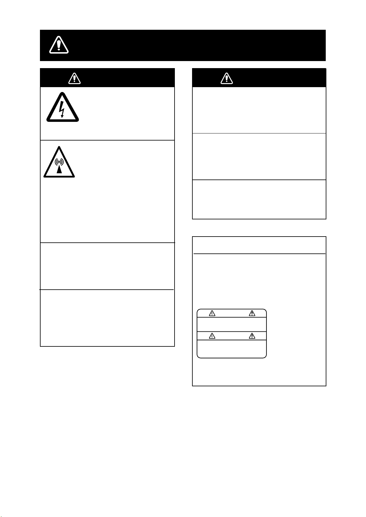
SAFETY INSTRUCTIONS
WARNING
ELECTRICAL SHOCK HAZARD
Do not open the equipment.
Only qualified personnel
should work inside the
equipment.
Turn off the radar power
switch before servicing the
antenna unit. Post a warning sign near the switch
indicating it should not be
turned on while the antenna
unit is being serviced.
Prevent the potential risk of
being struck by the rotating
antenna and exposure to
RF radiation hazard.
Do not disassemble or modify the
equipment.
WARNING
Use the proper fuse.
Fuse rating is shown on the equipment.
Use of a wrong fuse can result in equipment
damage.
Keep heater away from equipment.
Heat can alter equipment shape and melt
the power cord, which can cause fire or
electrical shock.
The useable temperature ranges are
Antenna unit: -25˚C to +70˚C
Display unit: -15˚C to +55˚C
CAUTION
WARNING LABEL
Fire, electrical shock or serious injury can
result.
Turn off the power immediately if water
leaks into the equipment or the equipment is emitting smoke or fire.
Continued use of the equipment can cause
fire or electrical shock.
The warning label shown below is
attached to the display unit. Do not remove
this label. If the label is peeling off or is
illegible, contact FURUNO for replacement.
To avoid electrical shock, do not
remove cover. No user-serviceable
parts inside.
WARNING
Name: Warning Label (1)
Type: 86-003-1011-1
Code No.: 100-236-231
i
Page 4

COMPLIANCE WITH R&TTE DI RECTIVE 1999/5 /EC
This radar complies with the R&TTE Directive 1999/5/EC. In accordance with Article 6-3 of this
directive, FURUNO intends to put this radar on the market of the following countries in EU as well
other markets.
Austria, Belgium, Cyprus, Denmark, Estonia, Finland, France, Germany, Greece, Hungary, Ireland,
Italy, Latvia, Lithuania, Malta, Poland, Portugal, Slovenia, Spain, Sweden, The Netherlands, United
Kingdom, Iceland, Norway
ii
Page 5

TABLE OF CONTENTS
FOREWORD ..........................................iv
SYSTEM CONFIGURATION...................v
1. PRINCIPLE OF OPERATION .............1
2. OPERAT ION .......................................3
2.1 Turning the Radar On/Off.....................3
2.2 Transmitting, St and-by.........................3
2.3 LCD Tone and Brilliance.......................3
2.4 Control Description...............................4
2.5 Indications and Markers.......................5
2.6 Selecting the Range.............................5
2.7 Receiver Sensitivity..............................5
2.8 Suppressing Sea Clutter......................6
2.9 Suppressing Rain Clutter.....................7
2.10 Range Rings.........................................7
2.11 Cursor...................................................7
2.12 Menu Operation ...................................8
2.13 Heading Line........................................8
2.14 Control Panel Illumination....................8
2.15 Measuring the Range...........................9
2.16 Measuring the Bearing.........................9
2.17 Shifting the Display ............................10
2.18 Zoom ..................................................10
2.19 Target Trails........................................ 10
2.20 Guard Alarm Zone.............................. 11
2.21 Interference Rejector..........................12
2.22 Echo Stretch .......................................12
2.23 Watchman...........................................13
2.24 Navigation Data..................................13
2.25 Dis playing Navigation Data During
Stand-by .............................................14
2.26 Echoes in Blac k or White...................14
2.27 Selecting Ranges to Use....................14
3. RADAR OB SERVATION..................15
3.1 General...............................................15
3.2 False Echoes......................................16
3.3 SART..................................................18
3.4 Racon (Radar Beacon).......................20
4. MAINTENANCE,
TROUBLESHOOTING..................... 21
4.1 Maintenance.......................................21
4.2 Replacing the Fuse ............................21
4.3 Troubleshooting..................................23
4.4 Magnetron Replacement....................23
4.5 Antenna Motor Belt Replacement......23
SPECIFICA TIONS............................SP-1
Index
Declaration of Conformity
iii
Page 6

FOREWORD
A Word to FURUNO MODEL
1712 Owners
FURUNO Electric Company thanks you for
purchasing the MODEL 1712 Marine Radar. We
are confident you will discover why the
FURUNO name has become synonymous with
quality and reliability.
For over 50 years FURUNO Electric Company
has enjoyed an enviable reputation for quality
and reliability throughout t he world. This
dedication to excellence is furthered by our
extensive global network of agents and dealers.
Your radar is designed and constructed to meet
the rigorous demands of the marine
environment. However, no machine can
perform its intended function unless properly
installed and maintained. Please carefully read
and follow the operation and maintenance
procedures set forth in this manual.
We would appreciate feedback from you, the
end-user, about whether we are achieving our
purposes.
Features
Your radar has a large variety of functions, all
contained in a rugged plastic case. All controls
respond immediately to the operator’s
command and each time a key is pressed the
corresponding change can be seen on the
screen.
The main features of the MODEL 1712 are
• Traditional FURUNO reliability and quality in
a compact, light-weight and low-cost radar.
• High definition 7-inch LCD shows echoes in
four shades of gray.
• Compact and light-weight radome antenna
with precision 41 cm microstrip radiator.
• Automatic control of sensitivity and sea
clutter suppression for simplified operation.
• Targets can be displayed in gray on white
background or vice versa, for optimal viewing
under any lighting.
• On-screen alphanumeric readout of all
operational information.
Thank you for considering and purchasing
FURUNO.
• Standard features include Display Shift, EBL,
Echo Stretch, Target Trail, Guard Alarm,
Interference Rejector, VRM, Zoom.
• Guard zone watches for targets entering (or
exiting) a guard zone.
• Watchman feature transmits at set intervals
to watch for targets entering (or exiting) the
guard zone.
• Operates on 12 V or 24 V power and
consumes approx. 40 watts power.
• Position in latitude and longitude, speed, and
range and bearing to a waypoint can be
shown in the bottom text area. (Requires
navigation data input in NMEA 0183 format.)
• LCD equipped with temperature sensor
which maintains viewability under
temperature change.
iv
Page 7
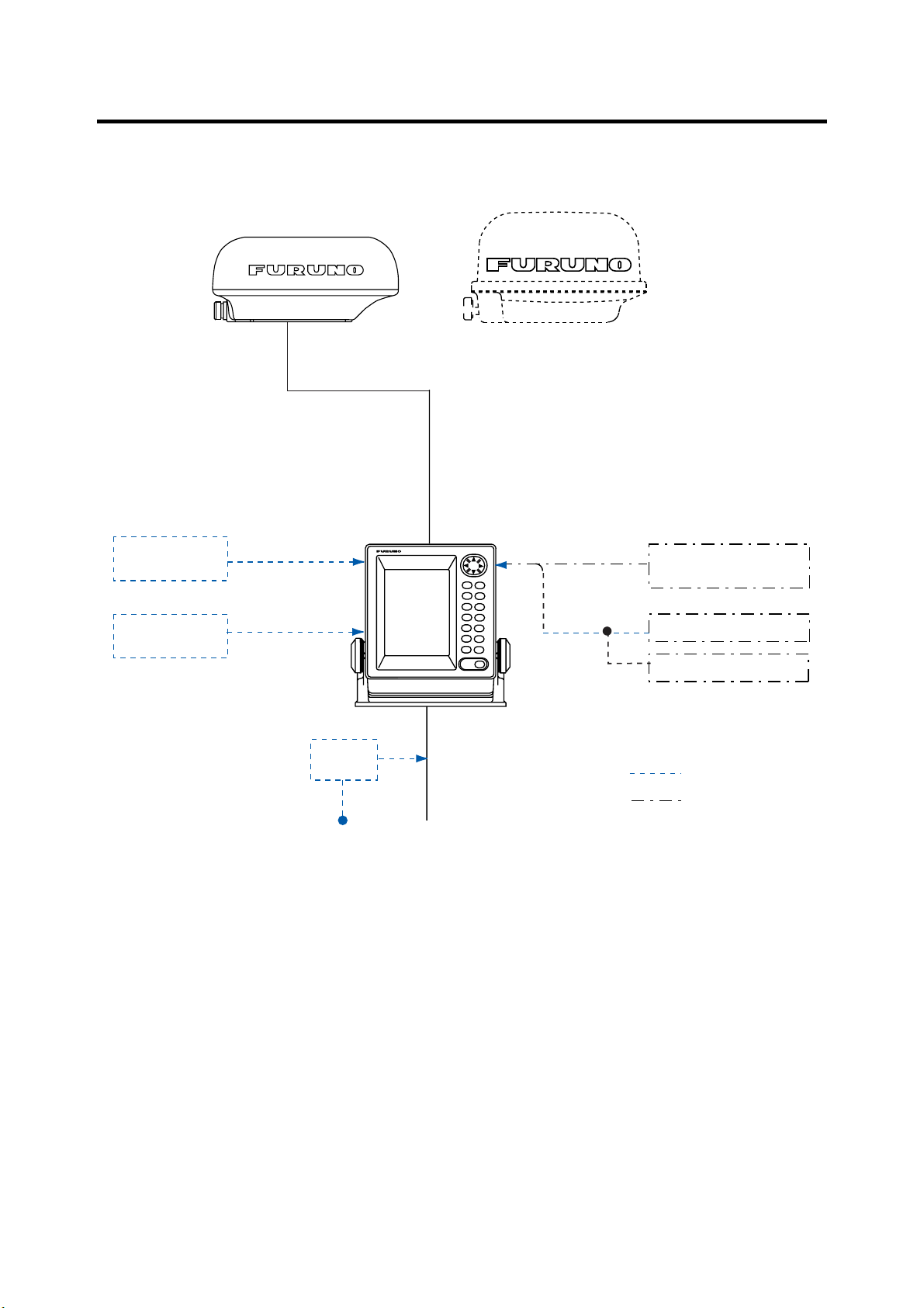
SYSTEM CONFIGURATION
ANTENNA UNIT
ANTENNA UNIT
RSB-0087
OR
DISPLAY UNIT
RDP-134
External Buzzer
OP03-168
RSB-0060
Navigator (GPS, etc.)/
Video Sounder
OR
Remote Display
FMD-1712
Rectifier
PR-62
Ship's Mains
100/110/
220/230 VAC
1φ, 50/60 Hz
12-24 VDC
NMEA 0183
Video Sounder
Navigator (GPS, etc.)
Option
Local Supply
v
Page 8

This page is intentionally left blank.
vi
Page 9

1. PRINCIPLE OF OPERATION
What is Radar?
The term RADAR is an acronym meaning RAdio
Detection and Ranging. It is a device which
measures the time it takes for a p ulsed signal to
be reflected back from an object.
How Ships Determined Position Before
Radar
The use of echoes to determine position did not
begin with radar. Ships would sound a short
blast on their whistles, fire a shot, or strike a bell
as an aid to navigation w hen running in fog near
a rugged shoreline. The time betw een t he
origination of the sound an d t he ret urning of the
echo indicated how far the ship w as from the
cliffs or the shore. The direct ion from which the
echo was heard indicated the rel at ive bearing of
the shore.
How Radar Determines Range
Radar determines the range t o t he t arget by
calculating the time difference between the
transmission of a radar signal a nd t he reception
of the reflected echo. It is a known fact t hat
radar waves travel at a nearly constant speed of
162,000 nautical miles per second. Therefore
the time required for a transmitted signal to
travel to the target and return as an echo t o t he
source is a measure of the range to the target .
Note that the echo makes a compl ete round tr ip,
but only half the time of trav el i s needed to
determine the one-way range to t he t arget . Thi s
radar automatically takes this into account in
making the range calculat ion.
How Radar Determines Bearing
The bearing to a target found by the radar is
determined by the direction in which the radar
antenna is pointing wh en it emits an electronic
pulse and then receives a return ing echo. Each
time the antenna rotates pulses are transmitted
in the full 360 degree circle, ea ch pulse at a
slightly different bearing from the previous one.
Therefore, if one knows t he direction in which
the signal is sent out, one know s t he direction
from which the echo must return.
Radar Wave Speed and Antenna
Rotation Speed
The speed of the radar waves out to t he t arget
and back again as echoes is extr emely fast
compared to the speed of rotation of the
antenna. By the time radar echoes h ave
returned to the antenna, the amount of antenna
rotation after initial transmission of the radar
pulse is extremely small.
The Radar Display
Targets are displayed on what is called a Plan
Position Indicator (PPI). This display is
essentially a polar diagram, w ith the tr ansmit tin g
ship’s position at the center. Images of target
echoes are received and disp layed at their
relative bearings, and at the ir distance from the
PPI center.
With a continuous displ ay of the images of
targets, the motion of targets is als o di splayed.
See the figure on the next page for a
comparison of actual situ ation and radar pict ure.
1
Page 10

Targets
A
D
A
Heading Line
Range and bearing
to a target, relative
D
to own ship, are
readable on the
screen.
B
(A) Bird's eye view
of situation
C
Own ship
(radar)
B
(B) Radar picture of (A)
C
Own ship
at center
Note: Target bow or stern
is not discriminated.
Figure 1-1 Comparison of rad ar pict ure and actual situation
2
Page 11
2. OPERATION
2.1 Turning the Ra dar On/Off
The [POWER] key turns the radar on/off. When
turning on the power, the control p an el lights
and the timer displays the t ime re ma ining for
warm up of the magnetron (the device which
transmits radar pulses), count ing down from
1:00 to 0:00.
Quick Start
Provided that the radar was once in use with
the transmitter tube (magnetron) still warm,
you can turn on the radar into TRANSMIT
status without the one-minute stand-by.
If the power switch has been turned off by
mistake and you want to restart the radar
promptly do the following:
1. Press the [POWER] key not later than five
seconds after power-off.
2. After ST-BY appears, press the [TX] key.
The radar is restored for full operation.
Note: If you press the [TX] key bef ore the
indication ST-BY appears, the buzzer sounds
and the radar does not transmit pulses.
When you won’t be using the radar f or an
extended period, but you want to keep it in a
state of readiness, press the [ TX ] key to set the
radar in stand-by. It is recommended to set the
radar in stand-by when it is not in use to extend
the life of the magnetron.
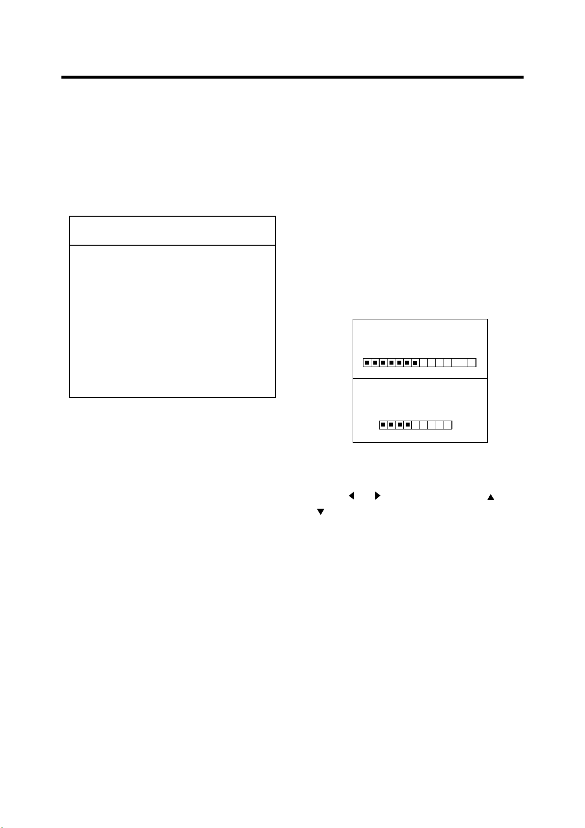
2.3 LCD Tone and Brilliance
1. Press the [TONE] key. The dialog box shown
in Figure 2-1 appears.
TONE: 12
▲
LOW HIGH
BRILL: 3
LOW ▼ ▲ HIGH
▲
2.2 Transmitting, Stand-by
After the power is turned on and the magnetron
has warmed up, ST-BY (Stand-By) appears at
the screen center, indicating the radar is ready
to transmit radar pulses.
Press the [TX] key to transmit. Echoes appear
in four levels of digitized video according to
echo strength. Note that w hen a target is
beneath a marker (VRM, EBL, heading line and
range ring) the part of the marker where the
target lies is display ed in reverse video.
Figure 2-1 Dialog box for adjust ment of
LCD tone and brilliance
2. Press
to adjust brilliance (0-9).
or to adjust tone (0-27); or
3
Page 12

2.4 Control Description
MENU
GAIN
FTC
TRAIL
TONE
GUARD
HL OFF
EBL
VRM
RINGS
RANGE
STC
SHIFT
ZOOM
TX
POWER
Shifts cursor, EBL,
VRM; selects items
on menus.
Omnipad
Opens/closes
the menu.
Turns EBL
on/off.
MENU
EBL
GUARD
HL OFF
VRM
RINGS
Decreases
the range.
Adjusts receiver
GAIN
RANGE
STC
sensitivity.
FTC
Suppresses
SHIFT
Activates/disables
the guard zone.
Press with [MENU]
to hide heading line.
T urns VRM on/off.
Press with [EBL] to
turn range rings
on/off.
Increases the
range.
Suppresses sea
clutter.
Shifts the display.
rain clutter.
Turns target trails
TRAIL
ZOOM
Turns zoom on/off.
on/off.
Adjusts LCD tone
and brilliance.
TONE
TX
Toggles between
transmit and
stand-by.
POWER
Turns power
on/off.
Figure 2-2 Control pane l
4
Page 13

2.5 Indications and Markers
Range
Range ring
interval
Zoom
(flashing)
Watchman
Guard
zone
Cursor
VRM
1.5
0.5
ZOOM
WATCHMAN
NM
3M TRAIL
G (IN)
FTC
ES
Target trails setting
Guard alarm (IN or OUT)
Rain clutter suppressor
IR
Echo stretch
Interference rejector
EBL
Heading line
Range rings
EBL bearing
VRM range
EBL
VRM
45.0˚
1.25
NM
Figure 2-3 Indications and markers
2.6 Selecting the Range
The range selected autom atically determines
the range ring interval, the number of range
rings and pulse repetition rate.
Press the [+] or [-] key to select a range. The
range and range ring interv al appear at the top
left-hand corner on the screen.
Range
Range ring
interval
Figure 2-4 Location of range and range
ring interval indications
6.0
2.0
NM
045.0°
3.35
NM
291.5˚
0.73
NM
Range and bearing
to cursor
2.7 Receiver Sensitivity
The [GAIN] key adjusts the sensitivity of the
receiver. It works in precisely the same manner
as the volume control of a broadcast receiver,
amplifying the signals received.
You can adjust the sensitivity manually, or let
the unit do it automatically. In either case, the
proper setting is such that the background
noise is just visible on the screen. Adjust the
sensitivity on the highest range since the
background noise is clearer on that range.
If you set up for too little sens itivity, weak
echoes may be missed. On the other hand
excessive sensit ivity yields too much
background noise; weak targets may be missed
because of the poor contrast bet ween desired
echoes and the background noise on the
display.
5
Page 14

Automatic adjustment of sensitivity
1. Press the [GAIN] key once or twice to di splay
the screen shown in Figure 2-5.
AUTO GAIN MOD
LOW HIGH
1 2 3
Figure 2-5 Dialog box for
automatic adjustment of gain
2. Press
or to set level desired: 1, Low; 2,
Normal; 3, High.
Manual adjustment of sensitivity
1. Transmit on long range.
2. Press the [GAIN] key once or twice to display
the screen shown in Figure 2-6.
MAN GAIN MOD
LOW HIGH
32
A common mistake is too over-adjust t he [ ST C]
key so that the surface clutter is completely
removed. By setting up for maximum S TC ef fect,
you will see how danger ous this can be; a dark
zone will be created near the center of the
screen, causing a loss of close-in target s. This
dark zone is even more dangerous if the
sensitivity has not been properly adjusted.
Always leave a lit tle surface c lutt er v isib le on the
screen. If no clutter is observed (on very cal m
waters), turn off the circuit.
Sea clutter at
screen center
STC adjusted;
sea clutter suppressed
Figure 2-7 Appearance of sea clut t er
Figure 2-6 Dialog box for
manual adjustm ent of gain
3. Press
or to set level desired. 61 levels
are available.
Note:
The dialog boxes for adjustment of
sensitivity are automat ically erased when there
is no Omnipad operation for 10 seconds. To
erase them quicker, press the [GAIN] key after
completing the setting.
2.8 Suppressing Sea Clutter
In rough weather, returns from the sea surface
are received over several mi les around ow n shi p
and mask nearby targets. This situation can be
improved by properly using the [STC] key.
If the STC setting is too low, targets will be
hidden in the clutter, while if it is set too high,
both sea clutter and targets will disappear from
the display. In most cases adjust the key until
clutter has disappeared to leeward, but a little is
still visible windward.
Automatic sea clutter control
1. Press the [STC] key once or twice to show
the dialog box shown in Figure 2-8.
AUTO STC MOD
LOW HIGH
1 2 3
Figure 2-8 Dialog box for
automatic adjustment of STC
2. Press
Normal; 3, High.
or to set level desired: 1, Low; 2,
6
Page 15

Manual adjustment of sea clutter
control
1. Press the [STC] key once or twice to di splay
the dialog box shown in Figure 2-9.
MAN STC MOD
LOW HIGH
32
Figure 2-9 Dialog box for manual
adjustment of STC
2. Press
or to set level desired. 61 levels
are available.
Note:
The dialog boxes for adjustment of STC
are automatically erase d w hen there is no
Omnipad operation for 10 seconds. To erase
them quicker, press the [STC] key after
completing the setting.
2.9 Suppressing Rain Clutter
In adverse weather, clouds, rain or snow
produce spray-like spurious echoes which
impair target detection over a lo ng distance.
These echoes can be suppr essed by turning on
the [FTC] key. FTC appears at the top righthand corner on the screen when the FT C
function is on.
FTC
2.10 Range Rings
The range rings are the concentric circ les
around own ship and they provide an estimate
of target range. The selected range sc al e
automatically determines the number of rings
and their interval is displayed at t he upper-lefthand corner on the screen.
To turn the range rings on or off, press the [EBL]
and [VRM] keys together.
2.11 Cursor
The cursor is always displayed and functions to
measure the range and bearing to a target .
Operate the Omnipad to place t he cursor on the
inside edge of the target for range measurement
or the center of the target for bearing
measurement. The range and b earing to the
cursor appear at the bottom right-hand corner
on the display.
6.0
NM
2.0
Target
Cursor
045.0°
3.35
NM
Range and
bearing to
cursor
Rain clutter
at screen center
FTC adjusted;
rain clutter suppressed
Figure 2-10 Appearance of rain cl ut t er
Figure 2-11 How to measure range and
bearing with the cursor
7
Page 16

2.12 Menu Operation
o
Table 1-1 Menu descript io n
The menu contains ten f unctions which
normally do not require frequent adjustment in
everyday operation. Basic menu operation is as
below.
Basic menu operation
1. Press the [MENU] key to display t he menu.
PRESS
ITEM,
1
2
3
4
5
6
Press ▼ at DIMMER;
change page. Default settings in highlight.
PRESS
ITEM,
7
8
9
10
▼ /▲
TO SELECT MENU
▲
▲
/
TO CHANGE SETTING.
ECHO STRETCH
INT. REJECT
NAV DATA
VIDEO
WATCHMAN
DIMMER
▲
DSPL ON STBY
TRAIL TIME
TRAIL BRILL
RANGE (NM)
RVS NOM
▼ /▲
TO SELECT MENU
▲
TO CHANGE SETTING.
/
Figure 2-12 Menu
ON OFF
ON OFF
ON
OFF
OFF
5M 10M 20M
0 1 2 3
▲
at DSPL ON STBY t
NAV OFF
CONT 30S
1M 3M 6M
LOW HIGH
1/8 1/4 1/2 3/4 1 1.5
2 3 4 6 8 12 16 24
Menu Item Description
1 ECHO
STRETCH
2 INT.
REJECT
Stretches echoes in the
range direction.
Suppresses radar
interference.
3 NAV DATA Turns navigation data
display on/off.
4 VIDEO Displays echoes in gray
or white.
5 WATCHMAN Turns watchman on/off.
6 DIMMER Adjusts control panel
illumination.
7 DSPL ON
STBY
8 TRAIL
TIME
9 TRAIL
BRILL
Turns navigation data
display in stand-by on/off.
Selects target trail plotting
time.
Selects target trail
brilliance.
10 RANGE Selects ranges to use.
2.13 Heading Line
The heading line ind icat es the ship’s heading
and it is the solid line which appears at zero
degrees on the bearing scale.
To temporarily erase the heading line to look at
targets existing dead ahead of own ship, press
the [MENU] and [GUARD] keys together.
Release the keys to display the line again.
2. Press
3. Press
or to select item
or to select option.
4. Press the [MENU] key to register your
selection and close the menu.
2.14 Control Panel Illumination
1. Press the [MENU] key to open the menu.
2. Select DIMMER.
3. Select level desired; 3 is the hi ghest level of
brilliance.
4. Press the [MENU] key to register your
selection and close the menu.
8
Page 17

2.15 Measuring the Range
2.16 Measuring the Bearing
The bearing to a target can be measured by t he
range rings, by the cursor (see paragraph 2.11)
and by the VRM (Variable Range Marker).
Measuring range by the range rings
Count the number of rings between t he center of
the display and the target. Check the range ring
interval at the top left-hand corn er of the screen
and judge the distance of the echo from the
inner edge of the nearest ring.
Measuring range by the VRM
1. Press the [VRM] key to turn on the VRM.
2. Within 10 seconds after turnin g on t he VRM,
that is, while "VRM" is highl ighted, press
(increase radius) or (decrease radius) to
place the VRM on the inside edge of the
target.
3. Check the VRM readout at the bot t om lefthand corner on the screen.
Note: The VRM b ecomes stationary when the
[VRM] key is pressed a second ti me, or 10
seconds elapses without pressing
When the VRM is stationary "VRM" is not
highlighted.
NM
6.0
2.0
or .
The bearing to a target can be measured by t he
cursor (see paragraph 2.11) and by the EBL
(Electronic Bearing Line).
Measuring bearing by the EBL
1. Press the [EBL] key to turn on the EB L.
2. Within 10 seconds after turnin g on the EBL,
that is, while "EBL" is highlight ed, press
(counterclockwise) or (clockwise) to bisect
the target with EBL.
3. Check the EBL readout at the bottom lefthand corner on the screen.
Note: The EBL becomes stationary when the
[EBL] key is pressed a second t i me, or 10
seconds elapses without pressing
When the EBL is st ationary "EBL" is not
highlighted.
6.0 NM
2.0
EBL
45.0°
EBL
bearing
045.0°
3.35
NM
or .
Target
Cursor
EBL
Cursor
bearing
Target
Cursor
VRM
VRM 2.42 NM
VRM
range
045.0°
2.42
NM
Cursor
range
Figure 2-13 How to measure range by the
cursor and VRM
To erase the VRM, press the [VRM] key until
the VRM disappears.
Figure 2-14 Measuring bear ing by
the cursor and the EBL
To erase the EBL, press the [EBL] key until the
EBL disappears.
9
Page 18

2.17 Shifting the Display
2.19 Target Trails
Your vessel's position can be shifted backward
by 1/3 of the range to increase the forward
range without changing the range or s iz e of
targets.
Press the [SHIFT] key to turn the shifted display
on/off.
Press
[SHIFT]
Normal display Shifted display
Figure 2-15 Shifting the d is play
2.18 Zoom
The zoom feature allows you to double the size
of the area between your vessel and any
location within the current rang e t o t ake a cl oser
look at an area of interest.
1. Select location to zoom with the cursor.
2. Press the [ZOOM] key.
Target trails are simulated afterglow of target
echoes that represent their movements relative
to own ship.
3M TRAIL
Figure 2-17 Target trails
Trail time
(3 min)
Starting target trail
Press the [TRAIL] key to start the echo tr ai l
function. "TRAIL" and the target trail time
selected appear at the top right-ha nd corner on
the screen. Then, afterglow start s ext ending
from all targets.
Canceling target trail
Press the [TRAIL] key to erase target trails and
target trail indications.
ZOOM on (flashing)
ZOOM
Cursor
1) Place cursor
where desired.
Figure 2-16 Zoom function
3. To turn off the zoom function, press the
[ZOOM] key again.
Note 1:
shifted.
Note 2:
range.
Zoom is inoperativ e when the display is
Zoom is not available on 0.125 (1/8) nm
Press
[ZOOM]
2) Press [ZOOM].
Cursor
Trail time
1. Press the [MENU] key to open t he menu.
2. Select TRAIL TIME (on page 2 of the menu).
3. Select target trail time desi r ed; continuous,
30 seconds, 1, 3 or 6 min as appropriate.
4. Press the [MENU] key to register your
selection and close the men u.
Trail brilliance
1. Press the [MENU] key to open t he menu.
2. Select TRAIL BRILL (on pa ge 2 of the
menu).
3. Select HIGH or LO W as appropriate.
4. Press the [MENU] key to register your
selection and close the men u.
10
Page 19

2.20 Guard Alarm Zone
Setting a guard zone
The guard alarm allows the oper at or t o set t he
desired range and bearing for a gu ard zone.
When ships, islands, landmasses, et c. violate
the guard zone the offending target flashes and
an aural alarm sounds to call the operator’s
attention. The alarm is triggered against targets
entering or exiting the guard z one depending on
guard zone type as below.
CAUTION
The alarm should not be relied upon as the
*
sole means for detecting possible collision
situations.
STC, FTC and GAIN controls should be
*
properly adjusted to be sure the alarm
system does not overlook target echoes
How guard zone type is determined
After the guard zone is set, the radar starts
searching for targets inside the guard zone for
about 8 to 12 seconds. The re su lts of the se arch
are shown at the top right-hand corner of the
display as “G (IN)” or “G (OUT).”
.
1. Operate the Omnipad to place t he cursor at
the top left-hand corner of the zone an d
press the [GUARD] key.
2. Operate the Omnipad to place t he cursor at
the bottom right-hand corner of the z one and
press the [GUARD] key.
Asterisk blinking
Mentally create
the guard zone to set.
GUARD
Guard
zone
to set
Guard
zone
Drag cursor
here.
1) Drag cursor to
top left corner of
zone and press
[GUARD].
* GUARD
* GUARD
Drag cursor
here.
G (IN):
This is the inward guard alarm and it
means no target was found in the g uard zone.
Thereafter the aural alarm sounds against
targets which enter the guard zone.
G (OUT):
This is the outward guard alarm and it
means a target was found in the guard zone.
Thereafter the aural alarm sounds against all
targets which exit the guard zone.
(a) Inward guard alarm (b) Outward guard alarm
Figure 2-18 Inward and outward guard alarms
Guard zone completed.
2) Drag cursor to
bottom right corner
of zone and press
[GUARD].
Figure 2-19 How to set a guard zone
3. Eight to twelve seconds later the indication G
(IN) or G (OUT) replaces the indication
GUARD.
Note:
When the radar range is les s t han one
half of the guard zone range, the guard zone
disappears and the indicat ion "UP RNG"
replaces G (IN) or G (OUT). If this happens,
raise the range to redisplay the guard zone.
11
Page 20

Silencing the aural alarm
2.22 Echo Stretch
When a target violates the guard zone, t he
target flashes and the aural alarm sounds. You
can silence the aural alarm by pressing the
[GUARD] key. When this is done, GUARD,
displayed in reverse video, rep laces G (IN) or G
(OUT). This means the guard a larm is
temporarily deactivated. Press the key again to
reactivate the alarm.
Canceling the guard zone and guard
alarm
Press and hold down the [GU ARD] key more
than two seconds to erase the guar d zone.
2.21 Interference Rejector
Mutual radar interference may occ ur in t he
vicinity of another shipborn e radar operating in
the same frequency band (9 GHz ) . I t is seen o n
the screen as a number of bright spikes either in
irregular patterns or in the form of usually
curved spoke-like dotted lin es extending from
the center to the edge of the picture. T his ty pe of
interference can be reduced by activ at in g t he
interference rejector . "IR" appears at the t op
right-hand corner when the interf erence rejector
is on.
On long ranges target echoes tend to shrink in
the range direction, making them difficult to see.
On short and medium ranges suc h as 1.5, 3 and
6 nm range scales, the same sized targets get
smaller on screen as they approach ow n ship.
This is due to the inherent propert y of the
radiation pattern produced by the antenna. To
enhance target video, use the echo st ret ch
feature.
Echo stretch
ON
ES
Echo
Echo
stretched
in range
direction
Echo stretch OFF Echo stretch ON
Figure 2-21 Echo stretch
1. Press the [MENU] key to open t he menu.
2. Select ECHO STRETCH.
3. Select ON or OFF as appropr iat e.
4. Press the [MENU] key to register your
selection and close the men u.
1. Press the [MENU] key to open t he menu.
2. Select INT. REJECT.
3. Select ON or OFF as appropr iat e.
4. Press the [MENU] key to register your
selection and close the men u.
Figure 2-20 Radar interference
ES appears at the top right-hand c orner on t he
screen when the echo stretch feature is on.
Note 1:
target pips but also returns from sea s urface,
rain and radar interference. For this reaso n,
make sure that these types of interference have
been sufficient ly suppressed before activating
the echo stretch.
Note 2:
ranges between 0.125 and 0.75 nautical miles.
Echo stretch magnifies not only small
Echo stretch is not available on the
12
Page 21

2.23 Watchman
2.24 Navigation Data
The watchman function p e riodically transmits
the radar for about one minute to check for
targets in the guard zone. If a target has
entered or exited the guard zone the aural
alarm sounds, watch man i s canceled and the
radar starts transmitting. This feature is usef ul
when you do not need to observe the radar
continuously but want to be alert ed to radar
targets in the guard zone. When the radar starts
transmitting, the buzzer sounds to alert the
operator.
Tx
1 min
Watchman
starts.
St-by
5, 10 or
20 min
* Timer appears and countdowns
time to Tx when 1:00 remains
in ST-BY.
*
Tx
1 min
St-by
5, 10 or
20 min
*
Figure 2-22 How watchman works
With navigation data input in NMEA 0183
format (IEC 61162-1), navigation data can be
displayed at the screen bottom.
Navigation data includes position, course,
speed, and range and bearing to destination
waypoint (if set on navaid).
NM
6.0
2.0
Waypoint
mark
WP
LL
EBL
VRM
17.0°
M
*
2.6
NM
34° 38.99'
135° 19.22'
45.0°
NM
2.42
N
E
CSE
18.0°
SPD
4 .3
255.0°
3.35
Course
M
*
Speed
KT
NM
Turning watchman on/off
1. Set a guard zone. (See “Setting a guard
zone” on page 11.)
2. Press the [MENU] key to open the menu.
3. Select WATCHMAN.
4. Select transmitting interval or turn watchman
off. .
5. Press the [MENU] key to register your
selection and close the menu.
"WATCHMAN" appears at the top left-han d
corner on the screen when watchman is active.
Note: If no guard zone is set , t he buzzer
sounds when the radar starts transmitting.
Canceling watchman
Bearing and range to waypoint
*- Bearing suffixed with M
(Magnetic bearing) or T (True bearing).
Own ship position
Figure 2-23 Sample nav igation data display
Note 1: External sensor mu st be capable of
outputting such data to show it on this radar.
Note 2: A loc at io n shows three bars (- - -) when
there is no corresponding data.
Note 3: To receive data from mult iple
equipment, all data must be combined int o one
data line by a data- mixing device.
Note 4: Magnetic and t r ue bearing may be
selected alternately by pressing and holding
down the [GAIN] key.
Turning on the navigation data display
1. Press the [MENU] key to open the menu.
Press any key at any time. If done while
transmitting, watch man is disabled and the
normal display appears. In stand-by, the timer
appears and counts down from one minute, and
then the radar goes into stand-by.
2. Select NAV DATA.
3. Select ON.
4. Press the [MENU] key to conclud e.
13
Page 22

Turning the waypoint mark on/off
The destination waypoint set on a navigator
may be shown on the radar display. It is shown
by a dashed ring which is connected to the
screen center by a dashed line. (See Fi gure
2-23.) You can turn this mark on and off
alternately by pressin g t h e [FTC] and [SHIFT]
keys together.
2.25 Displaying Navigation
Navigation data may be displayed during
stand-by (requires external sensors) as follows:
1. Press the [MENU] key to open the menu.
2. Select DSPL ON STBY.
Data During Stand-by
Unit of measurement for depth and
water temperature
The unit of measurement for depth and water
temperature (external sensors required) can be
selected with the [EBL] key in the sequence of
Meters/Centigrade, Feet/Fahrenheit,
Fathoms/Centigrade.
Note: The unit of depth measurement availab le
depends on the data sentence output by
external equipment as below.
DBT(Ver.1. 5) Met ers, feet and fathoms
DPT(Ver.2. 0) Met ers only
2.26 Echoes in Black or White
3. Select NAV.
4. Press the [MENU] key to register your
selection and close the menu.
WP
215.5°M
12.5NM
CSE SPD
210.5° 12KT
LL
34°42.25' N
135°24.12' E
36378.1
TD
59096.4
TEMP
18.5°C
DEPTH
1 2 5
M
Figure 2-24 Sample nav igation data
screen shown during stand-by
Note: Nav data can be accepted from two
sources: navigator and vid eo sounder. When
two of the same type of device is out putting
data to the radar and the data is not identical,
the two sets of data are displayed alternately.
The default setting displays echoes in shades
of black on a white backgr ound. However, you
may reverse this arrangement as show n bel ow
to suit lighting cond it ions. Note that the default
setting is restored whenever t he pow er is
turned off.
1. Press the [MENU] key to open the menu.
2. Select VIDEO.
3. Select RVS.
4. Press the [MENU] key to register your
selection and close the menu.
2.27 Selecting Ranges to Use
This radar has 14 ranges, some you may not
require. You can select the ranges to use as
follows:
1. Press the [MENU] key to open the menu.
2. Select RANGE.
3. Select (highlight) range to use and press the
[EBL] key. Ranges in use are highlighted.
4. Press the [MENU] key to register you
selection and close the menu.
14
Note: At least two ranges are left on
(highlighted).
Page 23

3. RADAR OBSERVATION
)
3.1 General
Minimum range
The minimum range is defined by the shortest
distance at which, using a sc ale of 1.5 or 0.75
2
nm, a target having an echoin g area of 10 m
still shown separate fro m the point representing
the antenna position.
It is mainly dependent on the pulselength,
antenna height, and signal processing such as
main bang suppression and digital quantizat ion.
It is a good practice to use a shorter range scale
as far as it gives favorable definit i on or clarity of
picture.
Maximum range
The maximum detecting range of the radar,
Rmax, varies considerably depending on
several factors such as the heig ht of the
antenna above the waterlin e, t he height of the
target above the sea, the size, shape and
material of the target, and the atmospheric
conditions.
Under normal atmospheric conditions, the
maximum range is equal to the radar horizon or
a little shorter. The radar horizon is longer than
the optical one by about 6% be cause of the
diffraction property of the radar signal. The
Rmax is given in the following equation.
R
= 2.2 x (h1 + h2
max
Where;
Rmax: Radar horizon (nautical miles)
h1: antenna height (m)
h2: target height (m)
is
For example, if the height of the a nt enna above
the waterline is 9 meters and the hei ght of the
target is 16 meters, the maximum radar range
is;
R
= 2.2 x (9 + 16 ) = 2.2 x (3 + 4) = 15.4 nm
max
It should be noted that the dete ction range is
reduced by precipitation (which absorbs the
radar signal).
Radar resolution
There are two important factors in radar resol ution (discrimination): bearing resolution and
range resolution.
Bearing resolution
Bearing resolution is the ability of the radar to
display as separate pips the e choes received
from two targets which are at the sa me range
and close together. It is proportional to the
antenna length and reciproc al ly proportional to
the wavelength.
Range resolution
Range resolution is the abi l it y to display as
separate pips the echoes received from two
targets which are on the same bearing and
close to each other. This is determined by
pulselength only. Practically, a 0.08
microsecond pulse of f ers t he discrimination
better than 35 m as do so with all F URUNO
radars.
Test targets for determining the range and
bearing resolution are radar reflect ors having an
2
echoing area of 10 m
.
Radar horizon
Optical horizon
Figure 3-1 Radar horizon
15
Page 24

Bearing accuracy
One of the most important features of the radar
is how accurately the bearin g of a target can be
measured. The accuracy of bearing
measurement basically depends on the
narrowness of the radar beam. However, the
bearing is usually taken relative to the ship’s
heading, and thus, proper ad justment of the
heading line at instal lat i on is an important factor
in ensuring bearing accuracy. To minimize error
when measuring the bearing of a target, put the
target echo at the extreme pos it ion on the
screen by selecting a suitab le range.
Range measurement
Measurement of the range to a target is al so a
very important function of the radar. Generally ,
there are two means of measuring ra nge: t he
fixed range rings and the variable ran ge marker
(VRM). The fixed range rings appear on the
screen with a predetermined interval and
provide a rough estimate of the rang e to a target.
The variable range marker’s dia meter is
increased or decreased so that the marker
touches the inner edge of the t arget , all owing
the operator to obtain more accurate range
measurements.
Radar
antenna
Radar
mast
Shadow sector
Figure 3-2 Shadow sectors
Multiple echoes
Multiple echoes occur when a tr ansmitted pulse
returns from a solid object li ke a large ship,
bridge, or breakwater. A second, a third or more
echoes may be observed on the di splay at
double, triple or other multiples of the actual
range of the target as shown below. Multiple
reflection echoes can be reduced and often
removed by decreasing the gain (sensitivity) or
properly adjusting the [S TC] key.
True
echo
3.2 False Echoes
Occasionally echo signals appear on the screen
at positions where there is no target or
disappear even if there are targets. T hey are,
however, recognized if you understa nd t he
reason why they are display ed. Typical false
echoes are described in this paragr aph.
Shadow sectors
Funnels, stacks, masts, or derricks in the pat h of
the antenna block the radar beam. If the angle
subtended at the antenna is more than a few
degrees, a non-detecting sector may be
produced. Within this sector targ et s can not be
detected.
Own ship
Target
Multiple
echo
Figure 3-3 Multiple echoes
16
Page 25

Sidelobe echoes
;
Virtual image
Every time the radar pulse is transmitted, some
radiation escapes on eac h side of the beam,
called sidelobes. If a target exist s where it can
be detected by the side lobes as w el l as t he
main lobe, the side lo be echoes may be
represented on both sides of the true echo at
the same range. Sidelobes show usu ally only on
short ranges and from strong targets. They can
be reduced through careful reduction of the gain
or proper adjustment of the [STC] key.
Target A
Target B
(Spurious)
Target B
(True)
Figure 3-4 Sidelobe echoe s
A relatively large target close to your ship may
be represented at two positions on t he screen.
One of them is the true echo directly reflected
by the target and the other is a false ec ho w hich
is caused by the mirror effe ct of a large object
on or close to your ship as shown in t he f ig ure
below. If your ship comes close to a large metal
bridge, for example, such a false e cho may
temporarily be seen on the screen.
Target ship
Own
ship
True
echo
Mirror image
of target ship
Figure 3-5 Virtual image
False
echo
17
Page 26

3.3 SART
Note: The SART (Search and Rescue
Transponder) information below is excerpted
from IMO SN/Circ 197 Operation of Marine
Radar for SART Detection.
A Search and Rescue Transponder (SART) may
be triggered by any X-Band (3 cm) radar within
a range of approximately 8 nm. Each radar
pulse received causes it to transmit a response
which is swept repetitively across the complete
radar frequency band. When interrogated, it first
sweeps rapidly (0.4 µs) through the band before
beginning a relatively slow sweep (7.5 µs)
through the band back to the starting frequency.
This process is repeated for a total of twelve
complete cycles. At some point in each sweep,
the SART frequency will match that of the
interrogating radar and be within the pass band
of the radar receiver. If the SART is within range,
the frequency match during each of the 12 slow
sweeps will produce a response on the radar
display, thus a line of 12 dots equally spaced by
about 0 .64 nautical miles will be sho wn.
General procedure for detecting SART
response
1. Use the range scale of 6 or 12 nm as the
spacing between the SART responses is
about 0.6 nm (1125 m) to distinguish the
SART.
2. Turn off the automatic clutter suppression.
3. Turn off the Interference Rejector.
General remarks on receiving SART
SART range errors
When responses from only the 12 low frequency
sweeps are visible (when the SART is at a
range greater than about 1 nm), the position at
which the first dot is displayed may be as much
as 0.64 nm beyond the true position of the
SART. When the range closes so that the fast
sweep responses are seen also, the first of
these will be no more than 150 meters beyond
the true position.
Radar bandwidth
When the range to the SART is reduced to
about 1 nm, the radar display may show also
the 12 responses generated during the fast
sweeps. These additional dot responses, which
also are equally spaced by 0.64 nm, will be
interspersed with the original line of 12 dots.
They will appear slightly weaker and smaller
than the original dots.
Screen B: When SART
is close
1.5 NM
Sweep time
95 µs
Lines of 12 dots
are displayed in
concentric arcs.
Own ship's
position
Radar receiver
bandwidth
Echo of
SART
Position of
SART
Position of
SART
Echo of SART
24 NM
Sweep start
Screen A: When SART
is distant
Radar antenna
beamwidth
Own ship's
position
9500 MHz
9200 MHz
7.5 µs
Low speed sweep signal
High speed sweep signal
SART mark
length
This is normally matched to the radar
pulselength and is usually switched with the
range scale and the associated pulselength.
Narrow bandwidths of 3-5 MHz are used with
long pulses on long range and wide bandwidths
of 10-25 MHz with short pulses on short ranges.
Any radar bandwidth of less than 5 MHz will
attenuate the SART signal slightly, so it is
preferable to use a medium bandwidth to ensure
optimum detection of the SART.
Figure 3-6 Appearance of SART signal
on the radar display
18
Page 27

Radar side lobes
FTC control
As the SART is appro ached, sidelobes from the
radar antenna may show the SART responses
as a series of arcs or concentric rings. These
can be removed by the use of the anti-clut t er
sea control although it may be operationally
useful to observe the sidelobe s as t hey may be
easier to detect in clutter conditions and also
they will confirm that the SART is near to the
ship.
Gain
For maximum range SAR T det ection the normal
gain setting for long range detectio n should be
used, that is, with background n oise speckle
visible.
STC control
For optimum range SAR T det ection, this control
should be set to the minimum. Care should be
exercised as a wanted target in sea clut t er may
be obscured. Note also that in c lutt er conditions
the first few dots of the SART respo nse may not
be detectable, irrespective of the setting of the
anti-clutter sea control. In t his case, the position
of the SART may be esti mated by measuring
9.5 nm miles from the furthest dot bac k towards
own ship.
This should be used nor mal ly (to break up areas
of rain) when trying to detect a SART response
which, being a series of dots, is not affected by
the action of the anti-clutter rain circuitry. Note
that Racon responses, which are often in the
form of a long flash, will be affected by the use
of this control.
Some sets have automatic/manual anti-clutter
rain control facilities in wh ich case the operator
should switch to manual.
When the range to the SART is reduced to
about 1 nm, the radar display may show also
the 12 responses generated during t he f ast
sweeps. These additio nal dot responses, which
also are equally spaced by 0.64 nm, will be
interspersed with the orig inal line of 12 dots.
They will appear slightly weaker and smaller
than the original dots.
Some sets have automatic/manual anti-clutter
sea control facilities in wh ich case the operator
should switch to manual.
19
Page 28

3.4 Racon (Radar Beacon)
A racon is a radar transponder which emits a
characteristic signal when triggered by a ship’s
radar (usually only the 3 centimeter band). The
signal may be emitted on the s ame frequency
as that of the triggering radar, in which case it is
superimposed on the ship's ra dar display
automatically.
The racon signal appears on the P PI as a radial
line originating at a point just beyond the
position of the radar beacon or as a M orse code
signal (see figure below) di splayed radially from
just beyond the beacon.
Racon
Figure 3-7 Appearance of racon
signal on the radar display
20
Page 29

4. MAINTENANCE, TROUBLESHOOTING
WARNING
Do not open the equipment.
Hazardous voltage which can
cause electrical shock exists
inside the equipment. Only
qualified personnel should
work inside the equipment.
4.1 Maintenance
Regular maintenance is important for good performance. A maintenance program should be
established and should at least include the items listed in Table 4-1.
Table 4-1 Maintenance program
Period Item Check point Action
3 to 6
months
6 months to
1 year
Fixing bolt s for
antenna unit
Antenna unit
cleanliness
Antenna unit
cover
LCD The LCD will, in time,
Display unit
connectors
Check for corr osi on and if ti ghtly
fastened.
Check for foreign material.
(Foreign m aterial on the
antenna unit can cause a
considerable drop in sensitivity.)
Check for cracks. Permanent
damage to the unit’s circ uitry will
result if water lea ks insi de.
accumulat e a coating of dust
which tends to dim the picture.
Check for tight connection and
corrosion.
Replace corroded bolts. Coat new
bolts with antic or r osive sealant.
Clean the antenna unit wi th a
freshwater-moistened cloth. Alcohol
may be used. Do not use
commercial cleaners to clean the
antenna unit ; they can remove
paint and markings.
If a crack is found, it should be
temporaril y repai r ed by usi ng a small
amount of sealing com pound or
adhesive. The unit shoul d then be
brought to your dealer for permanent
repairs.
Wipe the LCD gently with a soft
cloth. Do not use comm ercial
cleaners to clean t he LCD; t hey c an
remove paint and marki ngs.
If corroded, contact your dealer
about replacem ent.
4.2 Replacing the Fuse
The fuse (5A) in the power cable protects the
equipment against reverse polarity of ship’s mains,
overcurrent and equipment fault. If the fuse blows, find
the cause before replacing it.
CAUTION
Use the proper fuse.
Use of a fuse of the wrong amperage will
damage the equipment and void the
warranty.
21
Page 30

4.3 Troubleshooting
Table 4-2 provides simple troubleshooting procedures which the user can foll ow to restore normal
operation.
Table 4-2 Troubleshootin g
If… But… Then…
you pressed the [POWER] key to
turn on the radar
the radar has warmed up and you
pressed the [TX] key to transmit
you adjusted sensitivity (with the
FTC switched OFF)
A key is pressed nothing happens key may be faulty. Contact your
• the control panel does not
light
• nothing appears on the
display
display contrast is poor try adjusting LCD tone.
“HD-SIG-MISS” or
“BP-SIG-MISS” appears on
the display
neither noise or targets
appear (characters and
markers do)
neither indications or
markers do (noise and
targets do)
• adjust DIMMER on the menu.
• battery may have discharged.
• check if fuse in power cable has
blown.
check that the signal cable is tightly
fastened.
check signal cable for damage.
check signal cable for damage.
dealer.
4.4 Magnetron Replacement
When the magnetron has exp ired distant targets c annot be seen on the d isplay. If this occurs, contact
a FURUNO agent or dealer about replacement of the magnetron.
Name Type Code No.
Magnetron E3588 000-142-270
4.5 Antenna Motor Belt Replacement
When the antenna motor belt has worn out, the sweep is not synchron ized with antenna rotation,
which results in abnormal picture. If this occurs, contact a FURUNO agent or dealer about
replacement.
Name Type Code No.
Antenna Motor Belt 40 S2M 266UG 000-808-743
22
Page 31

SPECIFICATIONS OF MARINE RADAR
MODEL 1712
1. GENERAL
(1) Indication System PPI Daylight display, raster scan, 4 tones in monochrome
(2) Range, Pulse length (PL) & Pulse Repetition Rate (PRR)
Range (nm) Pulse length (µs) PRR (Hz
approx.)
0.125 to 0.75 0.12 2100
1 to 2 0.3 1200
3 to 24 0.8 600
(3) Range Resolution 29 m
(4) Bearing Resolution 5.7º
(5) Minimum Range 41 m
(6) Bearing Accuracy Within ±1º
(7) Range Ring Accuracy 0.9 % of range or 8 m, whichever is the greater
2. SCANNER UNIT (RSB-0087: STANDARD, RSB-0060: OPTION)
(1) Radiator Micro-strip
(2) Polarization Horizontal
(3) Antenna Rotation Speed 24 rpm nominal
(4) Radiator Length 41 cm (RSB-0087), 32 cm (RSB-0060)
(5) Horizontal Beamwidth less than 5.2° (RSB-0087), less than 6.2° (RSB-0060)
(6) Vertical Beamwidth 25°
(7) Sidelobe Attenuation less than -20 dB
3. TRANSCEIVER MODULE
(1) Frequency and Modulation 9410 MHz ±30MHz (X band), P0N
(2) Peak Output Power 2.2 kW nominal
(3) Modulator FET Switching Method
(4) Intermediate Frequency 60 MHz
(5) Tuning Automatic
(6) Receiver Front End MIC (Microwave IC)
(7) Bandwidth 7 MHz
(8) Duplexer Circulator with diode limiter
(9) Time of Heat-up 1 minute approx.
SP - 1
Page 32

4. DISPLAY UNIT
(1) Picture Tube 7 inch rectangular monochrome LCD
240(H) x 320(V) dots, Effective radar display area: 240 x 240 dots
(2) Range, Range Ring Interval, Number of Rings
Range (NM) 0.125 0.25 0.5 0.75 1 1.5 2 3 4 6 8 12 16 24
Ring Interval (NM) 0.0625 0.125 0.125 0.25 0.25 0.5 0.5 1 1 2 2 3 4 6
Number of Rings 2 2 4 3 4 3 4 3 4 3 4 4 4 4
(4) Markers Heading Line, Bearing Scale, Range Rings,
Variable Range Marker (VRM), Electronic Bearing Line (EBL),
Alarm Zone, Waypoint Mark (navigation input required)
(5) Alphanumeric Indications Range, Range Ring Interval, Interference Rejection (IR),
Variable Range Marker (VRM), Electronic Bearing Line (EBL),
Stand-by (ST-BY), FTC
Guard Alarm (G(IN), G(OUT), UP RANGE), Echo Stretch (ES),
Range and Bearing to Cursor, * L/L Position, Echo Tailing (TRAIL),
Trailing Time, Watchman (WATCHMAN),
Zoomed Display (ZOOM), *Ship’s speed (SPD), *Ship’s Course
**Water temperature, **Water depth
*: Navigation data required, **: Echo sounder data required
(6) Input Data IEC 61162-1 adopted
Own ship’s position: GGA>RMA>RMC>GLL
Ship’s speed: RMA>RMC>VTG>VBW
Bearing (True): HDT>HDG
Bearing (Magnetic): HDM>HDG
*1
>HDM*1
*1
>HDT*1
Course (True): RMA>RMC>VTG
Course (Magnetic): VTG>RMA
Waypoint (Range, Bearing): RMB>BWC>BWR
Loran time difference: RMA>GLC>GTD
Water depth DPT>DBK>DBS>DBT
Water Temperature MTW
*1
: calculated by magnetic deviation
(7) Output Data
Alarm signal 12 VDC, 100 mA or less
Radar signal For radar remote display
5. POWER SUPPLY
(1) Rated Voltage/Current 12-24 VDC: 3.6-1.5 A
(2) Rectifier (option) 100/110/115/200/220/230 VAC, 1 phase, 50/60 Hz
SP - 2
Page 33

6. ENVIRONMENTAL CONDITI ON
(1) Ambient Temperature Scanner Unit: -25°C to +70°C
(IEC 60945) Display Unit: -15°C to +55°C
(2) Relative Humidity 93 % or less at +40°C
(3) Waterproofing Scanner Unit: IPX6
(IEC 60529) Display Unit: IPX5
(4) Bearing Vibration IEC 60945
7. COATING COLOR
(1) Display Unit Panel: N3.0, Chassis: 2.5GY5/1.5
(2) Scanner Unit N9.5 (upper), 2.5PB3.5/10 (lower)
8. COMPASS SAFE DISTANCE
(1) Display Unit Standard: 0.90 m Steering: 0.60 m
(2) Scanner Unit Standard: 1.25 m Steering: 0.85 m
SP - 3
Page 34

INDEX
AAAA
Antenna motor belt replacement.................. 22
BBBB
Bearing measurement.................................... 9
CCCC
Control description......................................... 4
Cursor............................................................. 7
DDDD
Depth unit .................................................... 14
Dimmer (panel brilliance ............................... 8
EEEE
EBL (Electronic Bearing Line)....................... 9
EBL key.......................................................... 9
Echo color ..................................................... 14
Echo stretch.................................................. 12
FFFF
False echoes.................................................. 16
FTC key.......................................................... 7
Fuse replacement......................................... 21
GGGG
NNNN
Nav data
in stand-by ................................................14
turning on/off.............................................13
PPPP
POWER key ....................................................3
RRRR
Racon ............................................................20
Range
deselecting.................................................14
measurement...............................................9
minimum and maximum...........................15
selecting ......................................................5
RANGE keys ([+], [-])......................................5
Range rings.....................................................7
SSSS
SART.............................................................18
Shadow sector...............................................16
SHIFT key.....................................................10
Sidelobe echoes .............................................17
STC key...........................................................6
System configuration...................................1-4
GAIN key........................................................ 5
Guard alarm................................................. 11
GUARD key.................................................. 11
HHHH
Heading line................................................... 8
IIII
Indications...................................................... 5
Interference rejector..................................... 12
MMMM
Magnetron replacement............................... 22
Maintenance................................................. 21
MENU key...................................................... 8
Menu operation .............................................. 8
Multiple echoes............................................. 16
TTTT
Target trails ..................................................10
TONE key .......................................................3
TRAIL key.....................................................10
Troubleshooting ............................................22
TX key.............................................................3
VVVV
Virtual image ................................................17
VRM (Variable Range Marker).......................9
VRM key .........................................................9
WWWW
Watchman.....................................................13
Water temperature unit................................14
ZZZZ
ZOOM key.....................................................10
Index-1
Page 35

Page 36

9-52 Ashihara-cho,9-52 Ashihara-cho,
A
A
*
00080898400
**00080898400
*
*
00080898400
**00080898400
*
*
OME
34890
H
30
**OME
34890
H
30
**OME
34890
H
30
**OME
34890
H
30
*
Nishinomiya 662-8580, JAPANNishinomiya 662-8580, JAPAN
Telephone :Telephone : 0798-65-21110798-65-2111
FaxFax 0798-65-42000798-65-4200
ll rights reserved.
ll rights reserved.
::
Printed in JapanPrinted in Japan
Pub. No.Pub. No. OME-34890OME-34890
Your Local Agent/Dealer Your Local Agent/Dealer
IRST EDITION :
IRST EDITION :MAYMAY 20002000
H3H3 ::MARMAR.. 11, 200511, 2005
Thepaperusedinthismanual
iselementalchlorinefree.
(( TATATATA ))
MODEL 1712MODEL 1712
* 0 0 0 8 0 8 9 8 4 0 0 ** 0 0 0 8 0 8 9 8 4 0 0 *
* O M E 3 4 8 9 0 H 3 0 ** O M E 3 4 8 9 0 H 3 0 *
 Loading...