

Furumo NAVpilot-711C Operator's Manual

AUTO PILOT
NAVpilot-711C
OPERATOR'S MANUAL
www.furuno.com
Model

FURUNO Authorized Distributor/Dealer
Printed in Japan
(Elemental Chlorine Free)
The paper used in this manual
is
elemental chlorine free.
9-52, Ashihara-cho,
Nishinomiya, 662-8580, JAPAN
All rights reserved.
Pub. No. OME-72780-A1
(REFU) NAVpilot-711C
A: OCT. 2013
A1: NOV. 14, 2013
00017829010

i
IMPORTANT NOTICES
General
• This manual has been authored with simplified grammar, to meet the needs of international users.
• The operator of this equipment must read and follow the descriptions in this manual. Wrong operation or maintenance can cancel the warranty or cause injury.
• Do not copy any part of this manual without written permission from FURUNO.
• If this manual is lost or worn, contact your dealer about replacement.
• The contents of this manual and equipment specifications can change without notice.
• The example screens (or illustrations) shown in this manual can be different from the screens
you see on your display. The screens you see depend on your system configuration and equipment settings.
• Save this manual for future reference.
• Any modification of the equipment (including software) by persons not authorized by FURUNO
will cancel the warranty.
• All brand and product names are trademarks, registered trademarks or service marks of their
respective holders.
How to discard this product
Discard this product according to local regulations for the disposal of industrial waste. For disposal
in the USA, see the homepage of the Electronics Industries Alliance (http://www.eiae.org/) for the
correct method of disposal.
How to discard a used battery
Some FURUNO products have a battery(ies). To see if your product has a battery, see the chapter
on Maintenance. Follow the instructions below if a battery is used. Tape the + and - terminals of
battery before disposal to prevent fire, heat generation caused by short circuit.
In the European Union
The crossed-out trash can symbol indicates that all types of batteries
must not be discarded in standard trash, or at a trash site. Take the
used batteries to a battery collection site according to your national
legislation and the Batteries Directive 2006/66/EU.
In the USA
The Mobius loop symbol (three chasing arrows) indicates that Ni-Cd
and lead-acid rechargeable batteries must be recycled. Take the used
batteries to a battery collection site according to local laws.
In the other countries
There are no international standards for the battery recycle symbol. The number of symbols can
increase when the other countries make their own recycle symbols in the future.
Cd
Ni-Cd Pb
ii
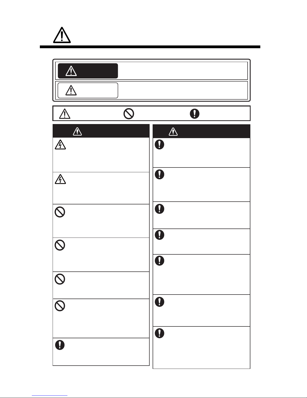
SAFETY INSTRUCTIONS
WARNING
Indicates a condition that can cause death or serious injury if
not avoided.
CAUTION
Indicates a condition that can cause minor or moderate injury
if not avoided.
Warning, Caution
Mandatory Action
Prohibitive Action
Please read these safety instructions before you operate the equipment.
Do not open the equipment unless
you are well familiar with electrical
circuits.
Only qualified personnel should work
inside the equipment.
WARNING
WARNING
WARNING
WARNING
Turn off the power at the switchboard
before beginning the installation.
Fire or electrical shock can result if the
power is left on.
Do not set the course changing
speed too high.
The boat will be turned too sharply at
the course change, which could create
a very dangerous situation.
Do not use the autopilot in the
following situations:
- Harbor entrance or narrow channel
- Where vessels change course often,
such as a cape or small island
Do not use the simulation mode on
the boat.
The rudder may move suddenly. This is
a special-purpose mode for technicians.
Do not use the ORBIT mode in rough
seas.
Because the boat turns a 360° circle
around the waypoint, a large wave or
strong wind can cause the boat to
capsize.
Observe the following cautions when
using the autopilot:
- Maintain a vigilant watch
- Watch for drifting of vessel
In an emergency, manually steer the
vessel.
The autopilot cannot avoid vessels, etc.
automatically.
Use the correct fuse.
Use of a wrong fuse can cause fire or
damage the equipment.
For the figure-eight mode, confirm that
no object is in the general vicinity
of the waypoint.
The distance from the waypoint to the
turning point depends on boat's speed.
Use the proper power cable.
Use JIS type DPY-2.5 or the equivalent.
Other types can cause fire.
When connecting a geomagnetic
heading sensor, correct magnetic field
deviation.
If an autopilot is used without the
compensation, unexpected course change
may occur.
Confirm that no one is near the rudder
when bleeding air from oil cylinder.
The rudder may move unexpectedly,
possibly causing bodily injury.
Set [Remote Controller 1/2] on the
[RC Setup] menu properly according to
remote controller connected.
If not done properly, malfunction may
occur. Especially, take care when
setting the NFU-type remote controller.
SAFETY INSTRUCTIONS
iii
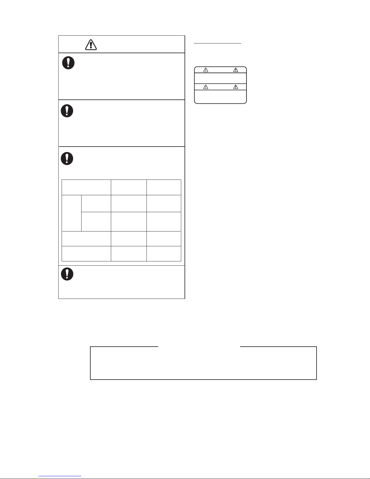
WARNING
To avoid electrical shock, do not
remove cover. No user-serviceable
parts inside.
CAUTION
CAUTION
Confirm that the power supply voltage
is compatible with the voltage rating
of the equipment.
Connection to the wrong power supply
can cause fire or damage the equipment.
Observe the following compass safe
distances to prevent interference to a
magnetic compass:
Separate the reversible pump at least one
meter from communications equipment,
communications antenna and communications cabling to prevent interference.
In case of power failure, turn off the
autopilot or manually steer the vessel.
Leaving the equipment in the AUTO or
NAV mode during power failure will
cause wear on the rudder mechanism
About the TCT LCD
The TFT LCD is constructed using the latest LCD techniques, and displays
99.99% of its pixels. The remaining 0.01% of the pixels may drop out or blink,
however this is not an indication of malfunction.
Standard Steering
compass compass
0.50 m
0.35 m
0.45 m
0.30 m
0.35 m
0.30 m
0.30 m
0.30 m
Remote Controllers
(Option)
Processor Unit
FAP-7002
Control
Unit
FAP-7011C
FAP-7001
䋨Option䋩
WARNING LABEL
A warning label is attached to the processor unit.
Do not remove the label. If the label is missing or
damaged, contact your dealer about replacement.
Name: Warning Label (1)
Type: 86-003-1011
Code No.: 100-236-231

iv
TABLE OF CONTENTS
FOREWORD ..................................................................................................................vii
SYSTEM CONFIGURATION ........................................................................................viii
EQUIPMENT LISTS........................................................................................................ix
1. OPERATIONAL OVERVIEW .................................................................................1-1
1.1 Controls......................................................................................................................1-1
1.2 How to Turn the Power On/Off................................................................................... 1-2
1.2.1 How to power the system...............................................................................1-2
1.2.2 How to power off the system..........................................................................1-2
1.3 How to Adjust the Brilliance .......................................................................................1-3
1.4 How to Set the Display Color .....................................................................................1-3
1.5 How to Select a Display .............................................................................................1-4
1.5.1 Graphic displays............................................................................................. 1-4
1.5.2 Numerical display...........................................................................................1-7
1.5.3 How to select the display data .......................................................................1-8
1.5.4 How to select the display data with the key operation (STBY mode only)... 1-10
2. STEERING MODES ...............................................................................................2-1
2.1 STBY Mode................................................................................................................ 2-1
2.2 AUTO Mode ...............................................................................................................2-1
2.2.1 How to get the AUTO mode...........................................................................2-2
2.2.2 Advanced AUTO mode .................................................................................. 2-3
2.3 NAV Mode.................................................................................................................. 2-4
2.3.1 How to get the NAV mode.............................................................................. 2-5
2.3.2 Sailing method for the NAV mode..................................................................2-6
2.3.3 Waypoint switching method ...........................................................................2-7
2.3.4 How to set the steering behavior of your boat after you arrive to a waypoint 2-8
2.4 Response Feature......................................................................................................2-9
2.4.1 How to activate the auto response feature..................................................... 2-9
2.4.2 How to activate the manual response feature................................................2-9
2.5 TURN Mode ............................................................................................................. 2-10
2.5.1 How to select a normal turn and start the turn ............................................. 2-10
2.5.2 Types of normal turns ..................................................................................2-11
2.6 FishHunter
TM
Mode ................................................................................................. 2-13
2.6.1 How to select a FishHunter
TM
turn and start the turn .................................. 2-13
2.6.2 Types of FishHunter
TM
turns........................................................................2-16
2.6.3 How to set FishHunter
TM
turn parameters ................................................... 2-20
2.7 How to Navigate to a TLL Position........................................................................... 2-21
2.8 DODGE Mode ..........................................................................................................2-22
2.8.1 How to dodge in the AUTO and NAV modes...............................................2-22
2.8.2 How to FU dodge in the STBY mode...........................................................2-22
2.8.3 How to NFU dodge in the STBY mode ........................................................ 2-22
2.9 REMOTE Mode........................................................................................................ 2-23
2.9.1 Dial-type remote controller (FAP-5551, FAP-5552) ..................................... 2-23
2.9.2 Button-type remote controller (FAP-6211, FAP-6212),
Lever-type remote controller (FAP-6221, FAP-6222) .................................. 2-24
2.9.3 Dodge-type remote controller (FAP-6231, FAP-6232)................................. 2-25
2.10 WIND Mode (for sailboats).......................................................................................2-26
2.10.1 How to get the WIND mode .........................................................................2-26
2.10.2 Wind angle mode ......................................................................................... 2-27
2.10.3 TACK mode..................................................................................................2-28

TABLE OF CONTENTS
v
2.10.4 Tacking in WIND mode (WIND TACK).........................................................2-30
2.11 OVRD mode (for IPS drive)......................................................................................2-34
2.12 Safe Helm Mode.......................................................................................................2-35
2.13 Power Assist Mode...................................................................................................2-37
3. ALARMS ................................................................................................................3-1
3.1 Alarm Menu ................................................................................................................3-1
3.2 Alarm Buzzer ..............................................................................................................3-2
3.3 Buzzer Interval............................................................................................................3-2
3.4 Watch Alarm...............................................................................................................3-3
3.5 Deviation Alarm ..........................................................................................................3-3
3.6 XTE Alarm ..................................................................................................................3-4
3.7 Arrival Alarm...............................................................................................................3-4
3.8 Speed Alarm...............................................................................................................3-5
3.9 Depth Alarm................................................................................................................3-5
3.10 Water Temperature Alarm ..........................................................................................3-6
3.11 Trip Distance Alarm, Trip Distance Reset ..................................................................3-7
3.11.1 How to set the trip log alarm...........................................................................3-7
3.11.2 How to reset the trip distance.........................................................................3-7
3.12 Wind Alarms (for sailboats) ........................................................................................3-8
3.12.1 Heading change alarm ...................................................................................3-8
3.12.2 Wind deviation alarm......................................................................................3-9
3.12.3 True and apparent wind speed alarm.............................................................3-9
3.13 Alarm Log .................................................................................................................3-10
4. USER MENU..........................................................................................................4-1
4.1 Parameter Setup ........................................................................................................4-1
4.1.1 Sea state ........................................................................................................4-1
4.1.2 Trim gain ........................................................................................................4-4
4.1.3 Speed calculation ...........................................................................................4-5
4.2 Rudder Drive Level (For Fantum Feedback
TM
)..........................................................4-5
4.3 Net Towing .................................................................................................................4-6
4.4 Course After Operation of a Remote Controller .........................................................4-7
4.5 Nav Data Source ........................................................................................................4-8
4.6 NavNet vx2 Synchronization ......................................................................................4-9
4.7 System Setup Menu ...................................................................................................4-9
4.8 Menu Shortcuts ........................................................................................................4-11
4.8.1 How to create a menu shortcut ....................................................................4-11
4.8.2 How to delete a menu shortcut.....................................................................4-11
5. MAINTENANCE, TROUBLESHOOTING ..............................................................5-1
5.1 Preventive Maintenance.............................................................................................5-1
5.2 Replacement of Fuse .................................................................................................5-2
5.3 Diagnostics.................................................................................................................5-2
5.3.1 Diagnostic menu.............................................................................................5-2
5.3.2 Processor unit test..........................................................................................5-3
5.3.3 Control unit test ..............................................................................................5-4
5.3.4 EVC interface test ..........................................................................................5-4
5.3.5 NMEA0183 test ..............................................................................................5-5
5.3.6 CAN bus test ..................................................................................................5-5
5.3.7 Key test ..........................................................................................................5-6
5.3.8 Screen test .....................................................................................................5-6
5.3.9 Rudder test.....................................................................................................5-7
5.3.10 Helm sensor test ..........................................................................................5-11
5.4 System Data.............................................................................................................5-12
5.5 Messages .................................................................................................................5-12

TABLE OF CONTENTS
vi
5.5.1 Message pop-up display .............................................................................. 5-12
5.5.2 Message board ............................................................................................5-13
5.5.3 Message description .................................................................................... 5-13
5.6 Sensor in Use Display.............................................................................................. 5-16
6. INSTALLATION AND WIRING ..............................................................................6-1
6.1 Installation ..................................................................................................................6-1
6.1.1 Installation location......................................................................................... 6-1
6.1.2 When FAP-7011 is replaced with FAP-7011C...............................................6-2
6.1.3 How to install the control unit ......................................................................... 6-3
6.2 Wiring .........................................................................................................................6-5
6.2.1 Wiring notices................................................................................................. 6-6
6.2.2 Connection with the processor unit................................................................6-7
7. INITIAL SETTINGS ................................................................................................7-1
7.1 How to Select Language and Units, Open the Installation Menu Window................. 7-1
7.2 Display Setup .............................................................................................................7-3
7.3 Ship’s Characteristics Menu.......................................................................................7-4
7.4 Dockside Setup Menu ................................................................................................ 7-5
7.4.1 Dockside setup for the rudder reference unit.................................................7-5
7.4.2 Dockside setup for Fantum Feedback
TM
.....................................................7-11
7.4.3 How to set the safe helm mode and power assist mode..............................7-15
7.4.4 Confirmation of the dockside setup.............................................................. 7-19
7.5 CAN bus Port Setup................................................................................................. 7-23
7.6 NMEA0183 Port Setup............................................................................................. 7-25
7.7 Sensor Setup ...........................................................................................................7-27
7.8 Universal Port Setup ................................................................................................7-28
7.8.1 GENERAL IN port setup ..............................................................................7-28
7.8.2 GENERAL OUT port setup .......................................................................... 7-29
7.9 Sea Trial...................................................................................................................7-30
7.9.1 How to calibrate the compass (PG-500/PG-700)......................................... 7-31
7.9.2 How to set the rudder deadband..................................................................7-33
7.10 Data Calibration ....................................................................................................... 7-34
7.11 Parameter Setup Menu ............................................................................................ 7-35
7.11.1 Sea state......................................................................................................7-35
7.11.2 Trim gain ......................................................................................................7-38
7.11.3 Speed calculation......................................................................................... 7-39
7.12 AUTO Option Menu..................................................................................................7-39
7.13 NAV Option Menu ....................................................................................................7-40
7.13.1 How to select the source for nav data.......................................................... 7-41
7.14 Fish Hunter Option Menu ......................................................................................... 7-42
7.15 Wind Option Menu ................................................................................................... 7-43
7.16 System Setup Menu.................................................................................................7-44
7.17 RC (Remote Controller) Setup Menu ....................................................................... 7-45
7.18 All Clear (Default Setting).........................................................................................7-45
APPENDIX 1 MENU TREE .......................................................................................AP-1
APPENDIX 2 JIS CABLE GUIDE .............................................................................AP-6
SPECIFICATIONS .....................................................................................................SP-1
PACKING LIST ............................................................................................................A-1
OUTLIBE DRAWING ...................................................................................................D-1
INTERCONNECTION DIAGRAM ................................................................................ S-1
INDEX..........................................................................................................................IN-1

vii
FOREWORD
A Word to the Owner of the NAVpilot-711C
Congratulations on your choice of the NAVpilot-711C. We are confident you will see why the FURUNO name has become synonymous with quality and reliability.
Since 1948, FURUNO Electric Company has enjoyed an enviable reputation for innovative and
dependable marine electronics equipment. This dedication to excellence is furthered by our extensive global network of agents and dealers.
Your equipment is designed and constructed to meet the rigorous demands of the marine environment. However, no machine can perform its intended function unless properly operated and
maintained. Please carefully read and follow the operation and maintenance procedures set forth
in this manual.
Thank you for considering and purchasing FURUNO.
We would appreciate feedback from you, the end-user, about whether we are achieving our purposes.
Features
• “Adaptive” technology allows NAVpilot to continually improve your vessel’s steering on every
voyage
• Auto set-up and self-learning for vessel speed and course
• Versatile, high-resolution color LCDs provide a variety of user-defined display configurations
• One-touch operation for STBY, NAV and AUTO modes
• “FishHunter
TM
” guides your vessel in circle, orbit, spiral, figure-eight, square or zigzag maneu-
ver around fish or other target
• Network up to six control units
viii
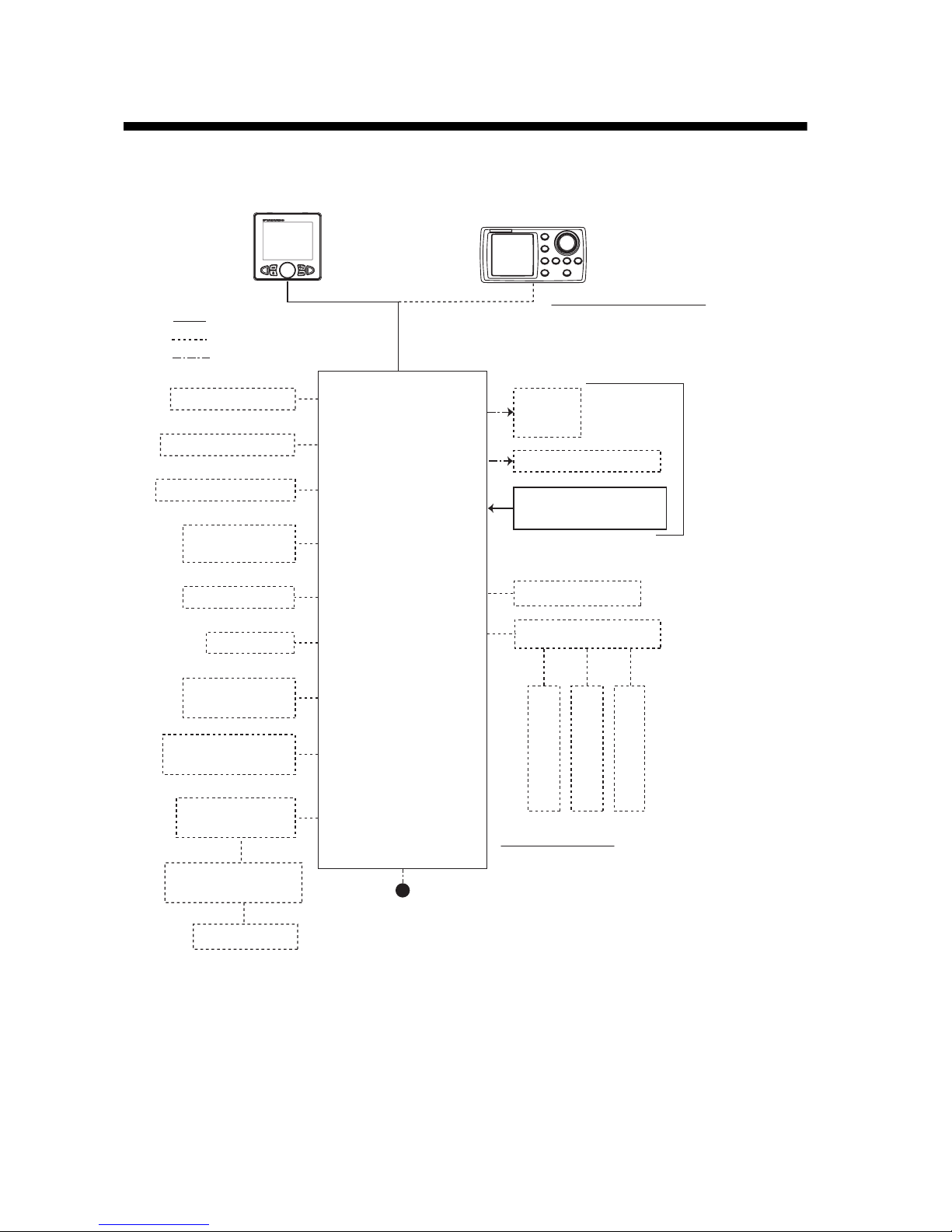
SYSTEM CONFIGURATION
Control Unit
FAP-7011C
Control Unit
FAP-7001
Contact Signal IN
Contact Signal OUT
PC (for serviceman)
Heading Sensor
PG-700
External Buzzer
Event Switch
NAV Equipment
(NMEA 0183)
CAN bus Equipment
(NMEA 2000)
IPS Interface Unit
IF-700IPS
Volvo IPS Gateway
Autopilot Gateway
EVC System*
4
12-24 VDC
Solenoid
Valve
Hydraulic Linear Drive
Rudder Reference Unit
FAP-6112*
2
Ship's
Steering
System*
3
Remote Controller
Distributor FAP-6800
Remote Controller
Remote Controller
Remote Controller
*1 : Attach the terminator (type: BD-07AFFM-LR7001) to the port not used on the last control unit
in the series.
*
2
: Not required for Fantum FeedbackTM ([Rudder Sensor] = [Fantum Feedback]).
*
3
: Not required for a IPS drive equipped vessel.
*
4
: For the EVC system available with the NAVpilot, contact your dealer.
Remote Controller:
Dial Type: FAP-5551, FAP-5552
Button Type: FAP-6211, FAP-6212
Lever Type: FAP-6221, FAP-6222
Dodge Type: FAP-6231, FAP-6232
Control Unit Qty: Max. 6*
1
The processor unit has two connection
lines for the control unit.
Three control units can be connected
per each connection line.
: Standard
: Option
: User Supply
Processor Unit
FAP-7002

ix
EQUIPMENT LISTS
Standard supply
Option supply
Name Type Code No. Qty Remarks
Control Unit
FAP-7011C - 1
Processor Unit
FAP-7002 - 1
Rudder Reference Unit
FAP-6112-200 - 1
May or may not be supplied
depending on order.
Installation
Materials
CP64-03101 001-082-720 1
For processor unit
CP64-02601 009-001-170 1
For rudder reference unit
May or may not be supplied
depending on order.
Spare Parts
SP64-01501 001-082-710 1
For processor unit, fuse
Sponge TZ8103008A - 1 For control unit, installation
materials
Cable Assy. BD-07AFFM-LR-150 001-081-180-10 1
Terminator BD-07AFFM-LR-7001
001-081-140-10 1
For control unit, accessory
Volvo Interface
Kit
FAP-6300 000-022-971 1
May or may not be supplied
depending on order.
Name Type Code No. Remarks
Control Unit
FAP-7001 -
Max. 5 optional units
FAP-7011C -
Max. 5 optional units
Remote Controller
FAP-5551
- Dial type, w/connector
FAP-5552
- Dial type, no connector
FAP-6211
- Button type, w/connector
FAP-6212
- Button type, no connector
FAP-6221
-
Lever Type, w/connector
FAP-6222
-
Lever Type, no connector
FAP-6231
- Dodge type, w/connector
FAP-6232
- Dodge type, no connector
Rudder Reference
Unit
FAP-6112-200 -
w/20 m cable
Junction
Box
FI-5002
- w/self-tapping screws
VOLVO Interface
Kit
FAP-6300 000-022-971
For the IPS drive equipped vessel
IPS Interface Unit IF-700IPS 000-022-972
VOLVO IPS
Gateway
AUTOPILOT-GATEWAY 000-022-974
Distributor
FAP-6800 000-090-242
For connection of three remote
controllers
Terminator
BD-07AFFM-LR7001 001-081-140-10

EQUIPMENT LISTS
x
Cable Assy.
MJ-A10SPF0001-060+ 001-081-150-10
For distributor, 6 m
MJ-A10SPF0001-120+ 001-081-160-10
For distributor, 12 m
BD-07AFFM-LR-100 001-081-170-10
For control unit, 10 m,
connector at one end
BD-07AFFM-LR-150 001-081-180-10
For control unit, 15 m,
connector at one end
BD-07AFFM-LR-200 001-081-190-10
For control unit, 20 m,
connector at one end
BD-07AF-07AF-LR-100 001-081-200-10 For control unit, 10 m,
connector at both ends
BD-07AF-07AF-LR-200 001-081-210-10 For control unit, 20 m,
connector at both ends
M12-05BFFM-010 000-167-965-10 CAN bus drop cable, 1 m, micro
M12-05BFFM-020 000-167-966-10 CAN bus drop cable, 2 m, micro
M12-05BFFM-060 000-167-967-10 CAN bus drop cable, 6 m, micro
CB-05BFFM-010 000-167-971-10
CAN bus drop cable, 1 m, micro,
mini
CB-05BFFM-020 000-167-972-10
CAN bus drop cable, 2 m, micro,
mini
CB-05BFFM-060 000-167-973-10
CAN bus drop cable, 6 m, micro,
mini
T-type
Connector
SS-050505-FMF-TS001 000-168-603-10
For CAN bus, micro+micro
NC-050505-FMF-TS001 000-160-507-10
For CAN bus, mini+micro
Termination
Resistor
LTWMC-05BMMTSL8001
000-168-604-10
For CAN bus, micro, male
LTWMN-05AMMTSL8001
000-160-508-10
For CAN bus, mini, male
LTWMC-05BFFTSL8001
000-168-605-10
For CAN bus, micro, female
LTWMN-05AFFTSL8001
000-160-509-10
For CAN bus, micro, male
Flush
Mount Kit
FAP-7001-FLUSH-KIT 001-082-730
For FAP-7001
Bracket
FAP-7001-BRACKET 001-082-750
For FAP-7001
Bracket Assembly
OP64-2 009-004-030
For FAP-5551/5552
Flush
Mount Kit
OP64-4 009-005-790
For FAP-6221/6222, panel type
OP64-5 009-005-800
For FAP-6221/6222, surface type
Name Type Code No. Remarks
1-1
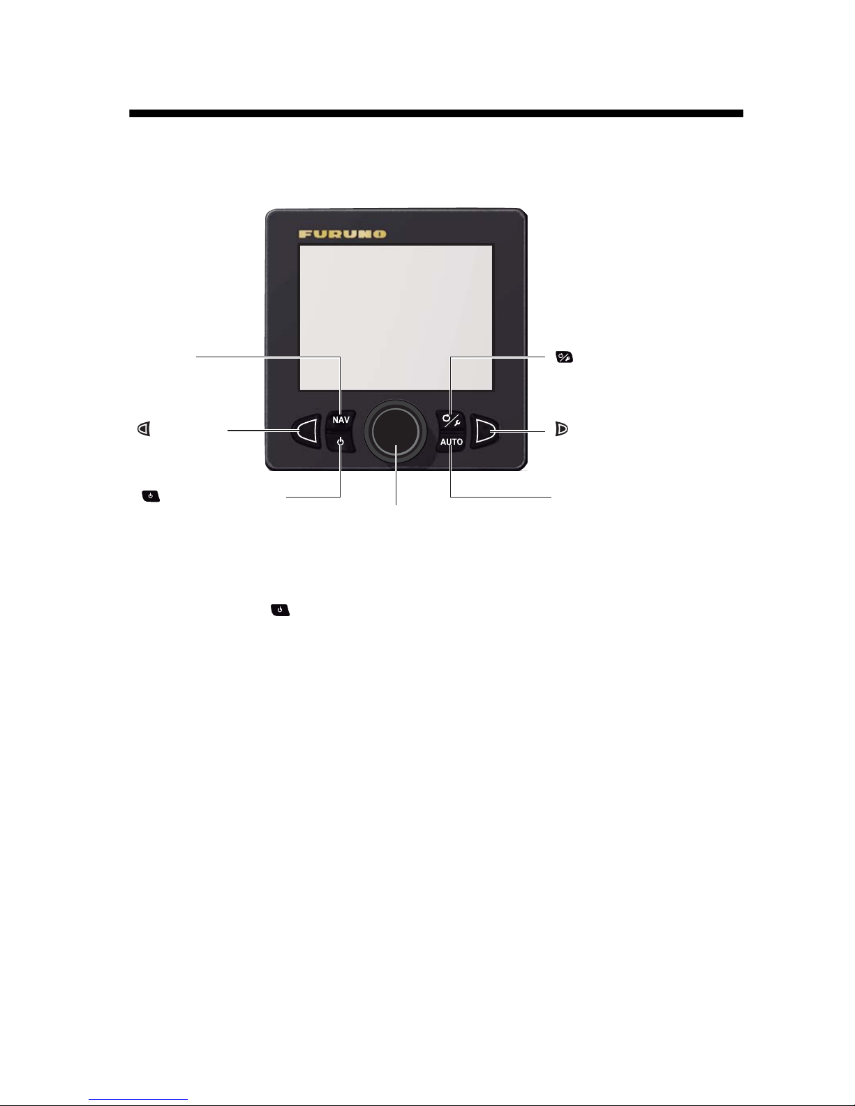
1. OPERATIONAL OVERVIEW
1.1 Controls
Press the and AUTO key simultaneously to get the WIND mode (sailboats only).
(MENU) key
Momentary press: Open the turn menu.
Long press: Open/close the menu.
NAV key
Select the NAV mode.
AUTO key
Select the AUTO mode.
(PORT) key
Steer boat to port.
(STBD) key
Steer boat to starboard.
(POWER/STBY) key
Momentary press:
• Turn on power.
• Go to the STBY mode.
Long press: Turn off power.
Course control knob
Rotate:
• Turn on power.
• Set course on the AUTO mode.
Push: Confirm menu setting.
1. OPERATIONAL OVERVIEW
1-2
1.2 How to Turn the Power On/Off
Note: When the heading sensor PG-500/PG-700 is connected, turn on the NAVpilot
and wait four minutes before you leave port. This allows time for the PG-500/PG-700
heading data to stabilize.
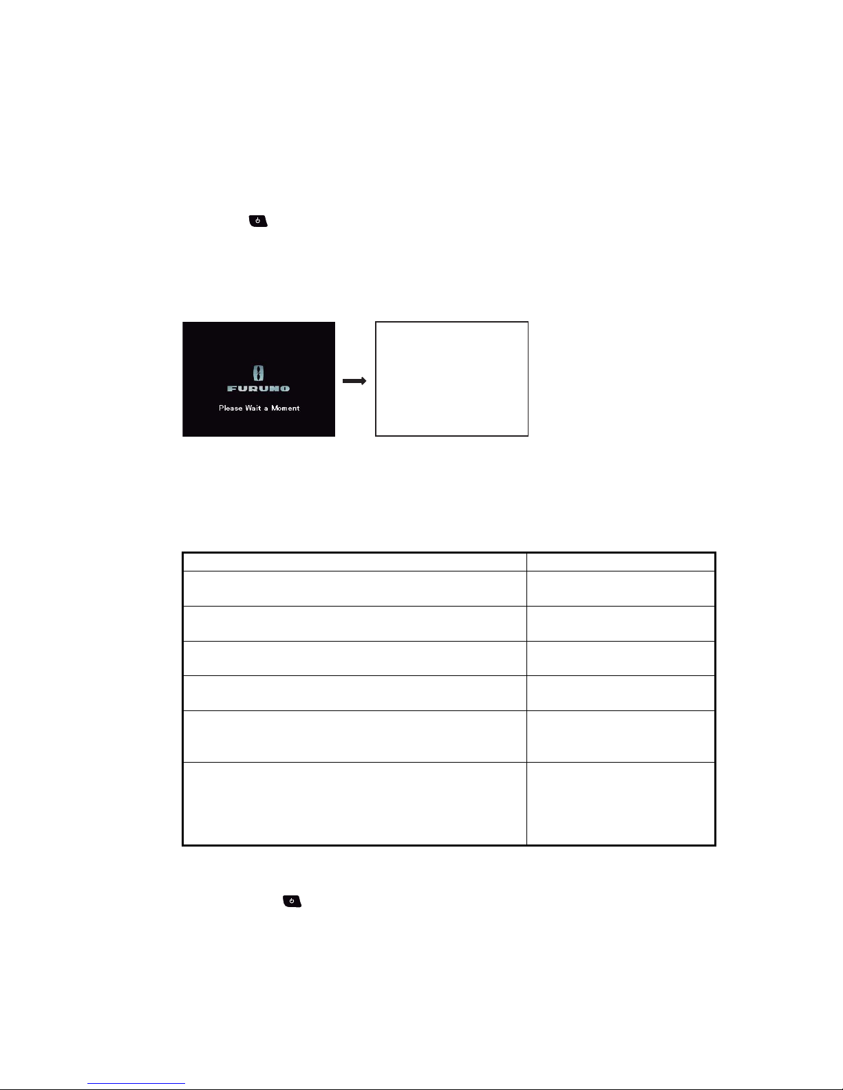
1.2.1 How to power the system
Press the key to power the system. A beep sounds and the result of the start up
test appears followed by the start screen. The startup test checks the ROM, RAM and
backup of the processor unit and control unit. The test also checks for the presence of
heading from the heading sensor and rudder angle information from the rudder reference unit.
Note: The content of the startup test changes according to your system configuration.
If “NG” appears for any item, an error message, shown in the table below, appears.
Follow the information provided in the message to restore normal operation. If you
cannot restore normal operation, contact your dealer.
1.2.2 How to power off the system
Long press the key to power off the system. While pressing the key, the display
shows the number of seconds remaining until the power is turned off.
Error message Meaning
System has failed startup test. Please contact a local
FURUNO representative for repair if problem re-occurs.
The system has failed the
start up test.
Back-up data is corrupt factory defaults will be restored
(processor). Push any key to continue.
Backup data of the processor
unit is corrupted.
Back-up data is corrupt factory defaults will be restored
(controller). Push any key to continue.
Backup data of the control
unit is corrupted.
Cannot receive heading data. Please check the heading
sensor.
Problem with heading sensor.
EVC Interface has failed startup test. Please contact a
local FURUNO representative for repair. Push any key
to continue.
System error of the IPS interface unit. Turn off the autopilot, contact your dealer.
No connect EVC Interface. Please check the EVC Interface. Push check the heading sensor.
The IPS interface unit is not
connected. Check the connection between the processor unit and IPS interface
unit.
NAVpilot-711C Startup Test
Processor 6454007-**.**
Controller 6454011-**.**
ROM RAM Backup
Processor OK OK OK
Controller OK OK OK
Heading Sensor OK xx.x°
RRU OK P12.3°
Controller ID: 1
**.** : Program version no.
1. OPERATIONAL OVERVIEW
1-3
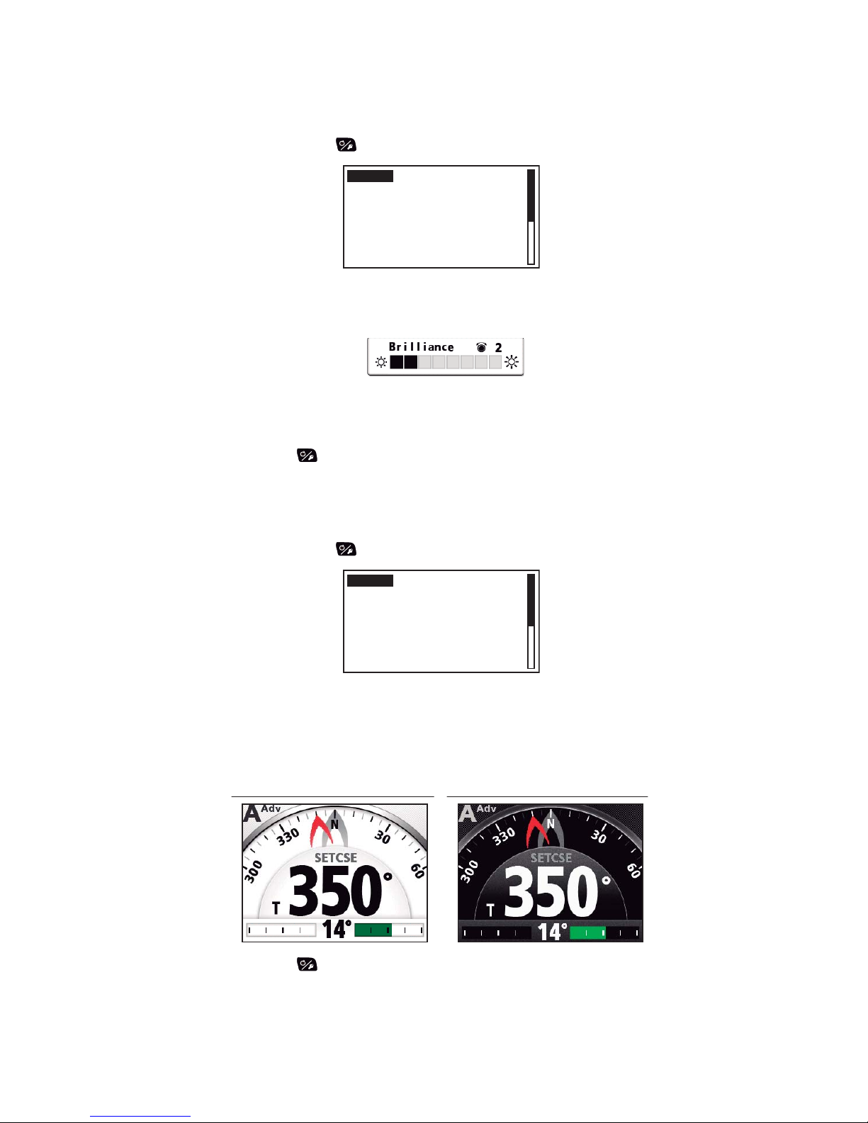
1.3 How to Adjust the Brilliance
Note: If the unit becomes hot, the brilliance is lowered automatically.
1. Long press the key to open the menu.
2. Rotate the Course control knob to select [Brilliance] then push the knob.
The brilliance adjust window appears. The window closes automatically when
there is no operation for a while.
3. Rotate the Course control knob to adjust the brilliance.
The higher the value, the brighter the display.
4. Push the Course control knob to close the window.
5. Push the key to close the menu.
1.4 How to Set the Display Color
1. Long press the key to open the menu.
2. Rotate the Course control knob to select the current setting for [Display Color]
then push the knob.
3. Rotate the Course control knob to select the display color.
[White]: White-themed display
[Black]: Black-themed display
4. Push the key to close the menu.
Message
Display Color : White
Sensor In Use
Brilliance
Advanced AUTO: ON
Net Towing AUTO : OFF
Message
Display Color : White
Sensor In Use
Brilliance
Advanced AUTO: ON
Net Towing AUTO : OFF
Example: [Display Color] = [White] Example: [Display Color] = [Black]
1. OPERATIONAL OVERVIEW
1-4
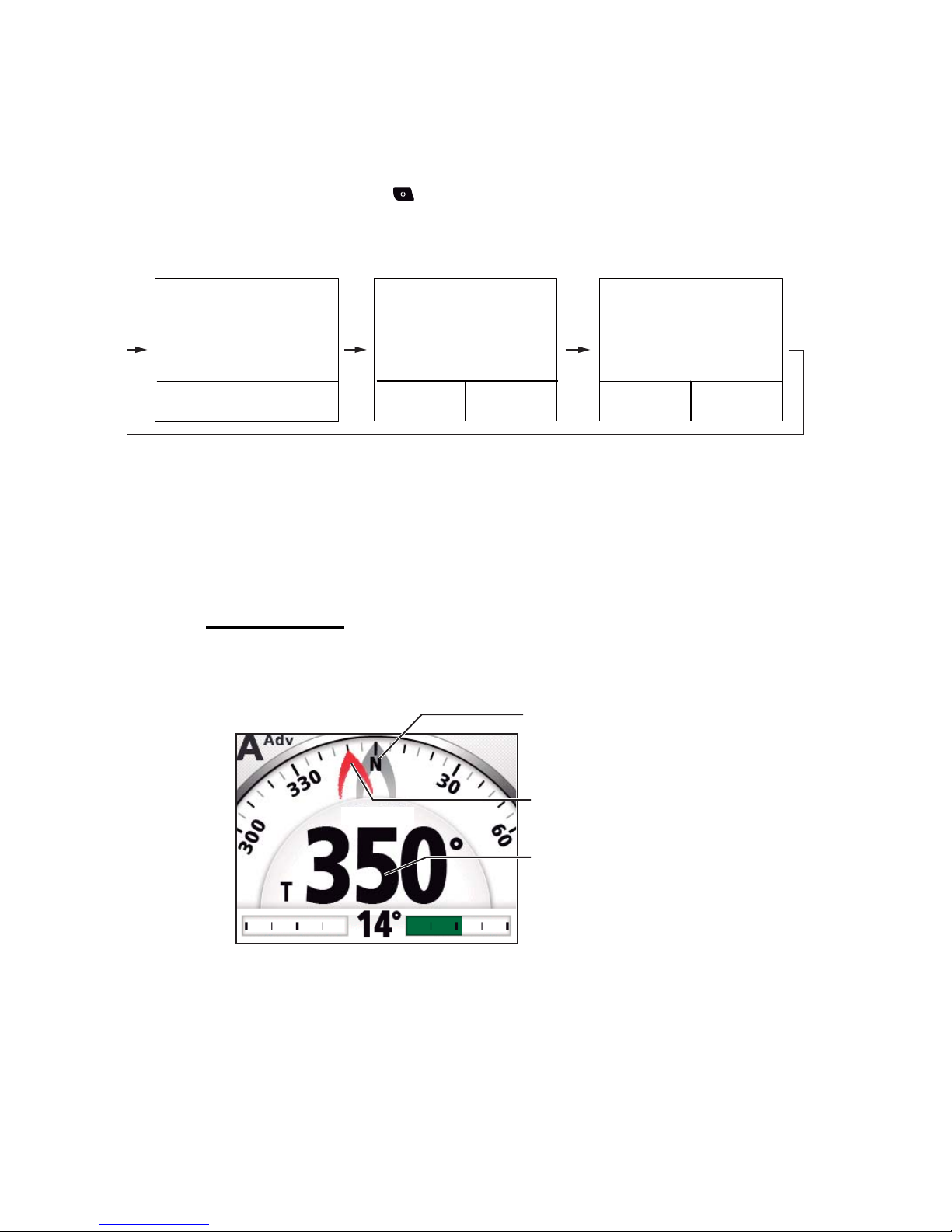
1.5 How to Select a Display
There are three displays to select from each steering mode.
To select a display, do the following operation according to the steering mode.
• STBY mode: Press the key
• AUTO and WIND mode: Press the AUTO key.
• NAV mode: Press the NAV key.
Note: Page layout of the page 3 depends on setting of [Data Box Format].
1.5.1 Graphic displays
There are five types of the graphic displays: compass, highway, wind, rudder, engine
speed display.
Compass display
The compass display show ship’s heading data. The compass rotates to keep the
ship’s heading (gray pointer) at the top of the display. Requires heading data.
㪲㪉㪴
䋪
㪲㪊㪴
䋪
㪲㪈㪴
䋪
Graphic
or
Numerical display
䋪
: Page no. appears when selecting display.
Graphic
or
Numerical display
Graphic
or
Numerical display
Data box
Data box
Data box
Analog indicator
Analog
indicator
SETCSE
SETCSE
Ship's heading
(Gray pointer)
Set course / waypoint cource
(Red pointer)
Steering mode data
(See page 1-6.)
1. OPERATIONAL OVERVIEW
1-5
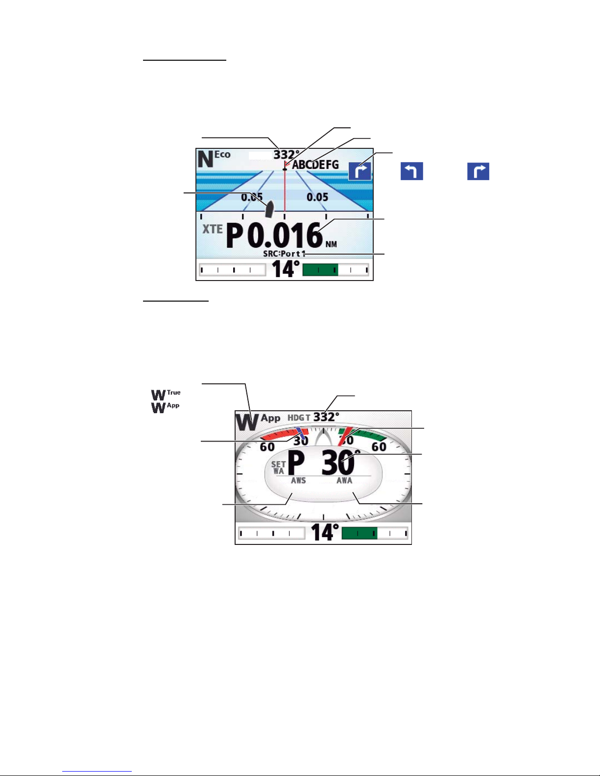
Highway display
The highway display provides a graphic presentation of your boat’s progress along its
intended course. The own ship marker moves according to your boat’s track to the
waypoint.
Wind display
The wind display shows wind angle and wind speed. The data can be shown in true
wind or apparent wind. The apparent wind is the actual flow of air acting upon a sail,
or the wind as it appears to the sailor. The true wind is the wind seen by a stationary
observer in velocity and direction. Requires a wind sensor.
Direction to next waypoint
Waypoint name
Own ship mark
HDG T
HDG T
Steering mode data
(See page 1-6.)
Data source
(Turn to STBD)(Turn to PORT)
Waypoint mark
Ship's heading
Wind mode:
Ship's heading
Set wind angle
(Blue pointer)
Wind angle
(Red pointer)
Steering mode data
(See page 1-6.)
Wind speed
Wind angle
S
30.0
30.0°
10.2
10.2
kn
kn
90
9 0
90
9 0
120
1 2 0
120
1 2 0
: True
: Apparent
1. OPERATIONAL OVERVIEW
1-6
Rudder display
The rudder display shows analog and digital rudder angle.
Note: Not available with Fantum Feedback
TM
.
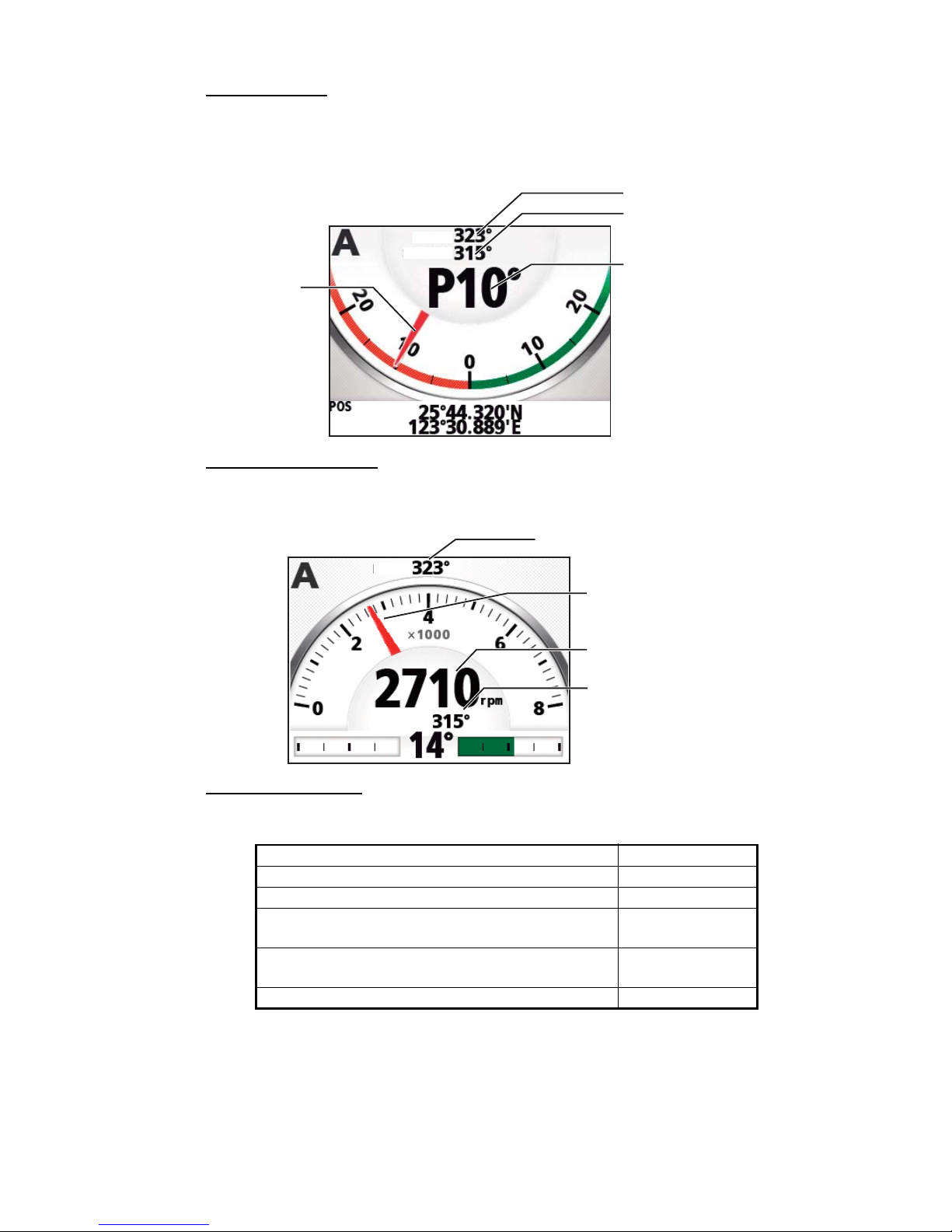
Engine speed display
The engine speed display shows the engine revolution. Requires engine speed data.
Steering mode data
The table below shows the steering mode data that appears on the graphic display.
Steering mode Display
STBY mode Ship’s heading
AUTO mode Set course
NAV mode
[NAV mode] = [Course]
Waypoint course
NAV mode
[NAV mode] = [XTE(Precision)] or [XTE(Economy)]
Cross-track error
WIND mode Set wind angle
SETCSE
SETCSE
HDG T
HDG T
Rudder angle/direction
P: to “port”
S: to “starboard”
Rudder angle
(Analog)
Ship's heading
Steering mode data
(See page 1-6.)
Ship's heading
Engine speed
(Analog)
Steering mode data
(See page 1-6.)
Engine speed
SETCSE
SETCSE
HDG T
HDG T
1. OPERATIONAL OVERVIEW
1-7
1.5.2 Numerical display
The numerical display provides relevant navigation data according to the steering
mode, on three screens.
The table below shows the layout and data provided with each steering mode.
Steering mode Layout Display data
STBY mode Type-1 A: Ship’s heading
AUTO mode A: Set course
NAV mode
([NAV mode] = [Course])
Type-2 B: Waypoint name
C: Waypoint course
D: Data source
NAV mode
([NAV mode] = [XTE(Precision)] or
[XTE(Economy)])
B: Waypoint name
C: Cross-track error
D: Data source
WIND mode Type-3 E: Set wind angle
F: Wind speed
G: Wind angle
㪘
㪜
㪝 㪞
㪚
㪛
㪙
Type-1 Type-2 Type-3

1. OPERATIONAL OVERVIEW
1-8
1.5.3 How to select the display data
You can select the display data to show in the STBY, AUTO, NAV, and WIND modes.
1. Long press the key to open the menu.
2. Rotate the Course control knob to select [Other Menu] then push the knob.
3. Rotate the Course control knob to select [System Setup] then push the knob.
4. Rotate the Course control knob to select [Display Data Select Menu] then push
the knob.
The window as shown below appears.
5. Rotate the Course control knob to select the steering mode desired then push
the knob.
6. Rotate the Course control knob to select the current setting for display division
desired then push the knob.
Note: Page layout of the page 3 depends on setting of [Data Box Format].
*: Sailboats only
Display Data Select Menu
STBY
AUTO
NAV
WIND*
Data 1
Page 1
Data 1
Data 2 Data 2Data 3 Data 3
Data 1
Data 2
Page 2
Page 3

1. OPERATIONAL OVERVIEW
1-9
7. Rotate the Course control knob to select display data desired then push the
knob.
The table below shows all the display data available.
*
1
: Not shown with Fantum FeedbackTM.
*
2
: Shown with Fantum FeedbackTM.
*
3
: Shown when [Data Box Format] = [2Boxes].
8. Push the key several times to close the menu.
Page/Data Data Displayed Data meaning
Graphic / numerical data
Page 1: [Data 1]
Page 2: [Data 1]
Page 3: [Data 1]
[Normal] Numerical display (see section 1.5.2)
[Compass] Compass rose
[Highway] Graphic presentation of progress to-
wards waypoint
[Wind Apparent] Analog and digital apparent wind direc-
tion speed
[Wind True] Analog and digital true wind direction
speed
[Rudder]*
1
Analog and digital rudder angle
[Engine Speed] Analog engine speed (revolution meter)
Analog indicator
Page 1: [Data 2]
Page 2: [Data 2]
[Rudder]*
1
Rudder angle
[Deviation] Heading deviation
For WIND mode, wind deviation
[Steering Direc-
tion]*
2
Steering direction
Data box
Page 2: [Data 3]
Page 3: [Data 2] / [Data 3]*
3
[POSN] Own ship’s position data
[COG] Course over ground
[SOG] Speed over ground
[STW] Speed through water
[Temp] Water temperature
[DPTH] Depth
[BRG] Bearing to waypoint
[RNG] Range to waypoint
[WPT] Waypoint position (Latitude/Longitude)
[XTE] Cross-track error
[TTG] Time-to-go to waypoint
[ETA] Estimated time of arrival to waypoint
[Date] Current date
[Time] Current time
[Wind Apparent] Apparent wind direction/speed
[Wind True] True wind direction/speed
[Volt] Input/output voltage to processor unit
[Trip] Trip distance
[Air Temp] Air temperature
[Atmos Press.] Atmospheric pressure
[Humidity] Humidity
[Dew Point] Dew point

1. OPERATIONAL OVERVIEW
1-10
1.5.4 How to select the display data with the key operation
(STBY mode only)
You can select the display data to show in the STBY mode with the key operation.
1. Short press the key to go to the STBY mode.
2. Press the key again to select a display.
3. Long press the Course control knob.
The item selected by the cursor is circumscribed with a thick rectangle, as in the
illustration below.
4. Press the or key to put the cursor on the data to change.
5. Rotate the Course control knob to select the display data then push the knob.
Cursor
2-1
2. STEERING MODES
This chapter describes the steering modes and functions of the NAVpilot.
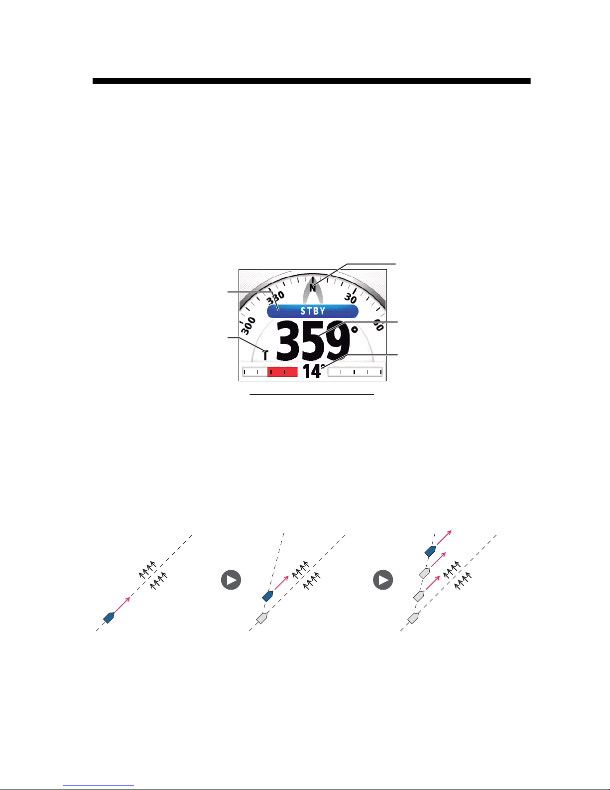
2.1 STBY Mode
After turning on the power, the equipment goes to the STBY mode. This is a manual
steering mode. When sailing into or out of a harbor, steer the vessel in the STBY mode
by using the steering wheel (helm) of your boat. In the STBY mode, “STBY“ appears
on the display.
The compass rotates to keep the ship’s heading (gray pointer) at the top of the display.
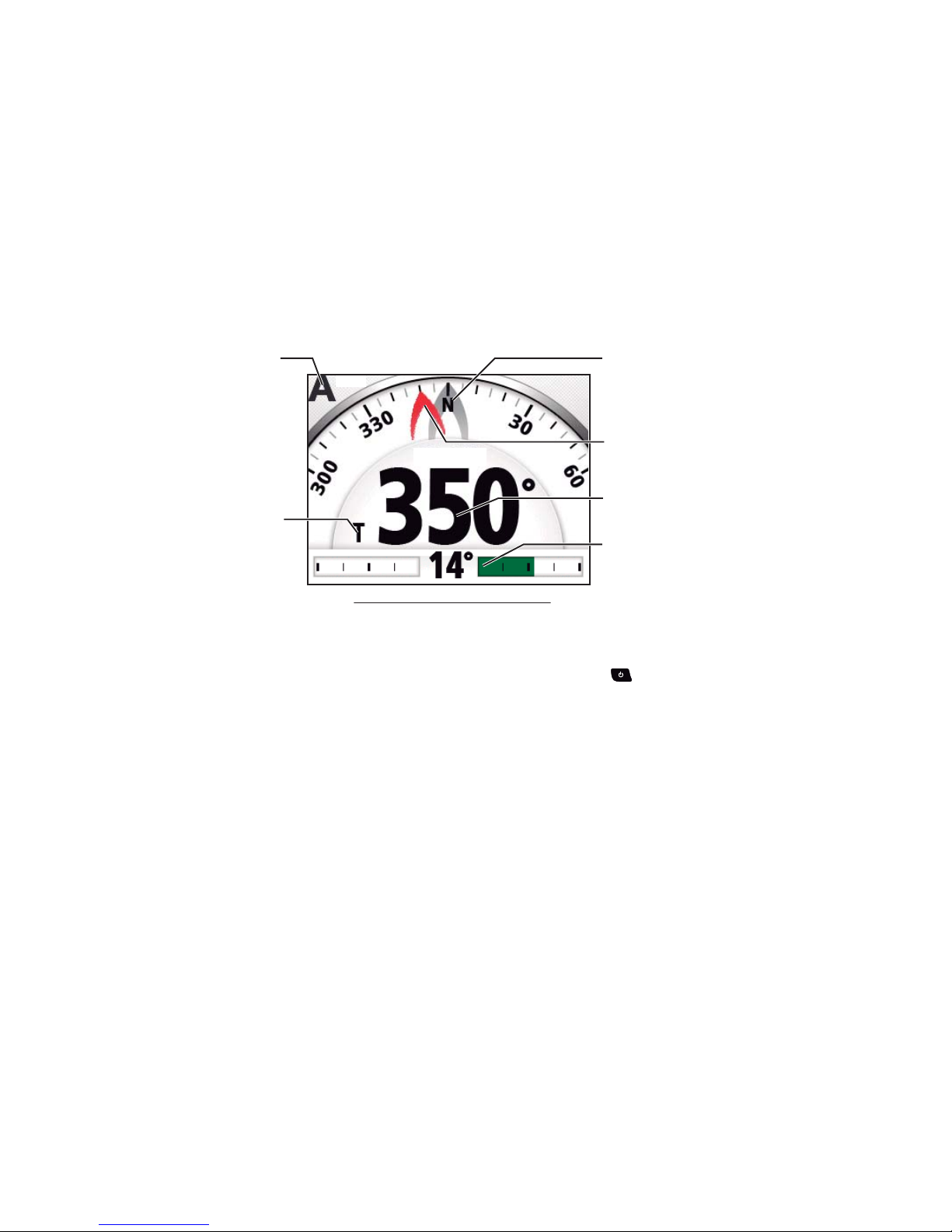
2.2 AUTO Mode
The AUTO mode steers the boat automatically on a course set by the operator.
The AUTO mode will not compensate for the effects of wind or tide, which can push
you off course athwart in the ship direction. Use the AUTO mode for short, straight
voyages. Otherwise switch to the NAV mode (see section 2.3).
Heading mode
T: True
M: Magnetic
Steering mode
Ship's heading
Analog indicator
or data box
Display example: STBY mode
Ship's heading
(Gray pointer)
Tide and Wind Tide and Wind Tide and Wind
2. STEERING MODES
2-2
2.2.1 How to get the AUTO mode
To get the AUTO mode, do as follows:
1. Direct the boat toward required course.
2. Press the AUTO key to activate the AUTO mode.
Your boat automatically maintains the current course when the AUTO key is
pressed. When the heading changes from the set course, the NAVpilot automatically adjusts the rudder to return the boat to the set course.
In the AUTO mode, the steering indication at the top left corner of the display
shows “A“.
The compass rotates to keep the ship’s heading (gray pointer) at the top of the
display.
3. To change the course setting in the AUTO mode, rotate the Course control knob
to the required course.
4. To exit the AUTO mode to steer manually, press the key. Steer your boat by
the helm.
SETCSE
SETCSE
Set course
Steering mode
Heading mode
T: True
M: Magnetic
Analog indicator
or data box
Display example: AUTO mode
Ship's heading
(Gray pointer)
Set course / waypoint cource
(Red pointer)
2. STEERING MODES
2-3
2.2.2 Advanced AUTO mode
The AUTO mode keeps a set course, but your boat’s course can change by the effects
of tide and wind. To adjust for the effects of tide and wind, use the Advanced AUTO
mode. The NAVpilot calculates your course according to your current position and
heading, then sets a virtual "waypoint" in its memory to navigate towards. If either tide
or wind begins to push you off course, the NAVpilot corrects your heading accordingly.
For use of the Advanced AUTO mode, connect a GPS navigator which outputs position data (Latitude and Longitude) to the NAVpilot.
To get the Advanced AUTO mode, do as follows:
1. In the AUTO mode, long press the key to show the menu.
2. Rotate the Course control knob to select the current setting for [Advanced AUTO] then push the knob.
[Advanced AUTO] also appears on the [AUTO Option] menu.
3. Rotate the Course control knob to select [ON] then push the knob. The steering
indication at the top left corner of the display changes as below. Select [OFF] to
quit the Advanced AUTO mode.
Note: When the position data is not input, the pop-up message “No Position Data“
appears and audio alarm sounds. Press any key to stop the alarm, then confirm
the connection with the GPS navigator.
4. Press the key to close the menu.
You can switch between AUTO and Advanced AUTO modes by holding down the
AUTO key three seconds to show the message "Advanced AUTO ON (OFF)".
Note: How strictly the Advanced AUTO mode keeps the course depends on the [NAV
Mode] setting in the [NAV Option] menu.
[NAV Mode] setting
• [Course] and [XTE(Economy)]
• [XTE(Precision)]
:
Keeps the course within 0.03 NM.
: Keeps the course within 0.01 NM.
Tide and Wind
Tide and Wind
Tide and Wind
OFF
ON
㪘
㪘
㪘㪻㫍
㪘㪻㫍
2. STEERING MODES
2-4
2.3 NAV Mode
NAVpilot steers the vessel towards the current waypoint while compensating for the
effects of tide and wind.
When connected to a GPS navigator, NAVpilot steers the vessel to follow a series of
waypoints in sequence. When you arrive at each waypoint or destination, audible and
visual alerts are activated.
The NAVpilot takes 15 seconds to activate the NAV mode after the NAVpilot receives
the destination information.
Waypoint Waypoint Waypoint
Tide and Wind Tide and Wind
Tide and Wind
Steering to a single waypoint
Waypoint Waypoint
Steering a route (a series of waypoints)
2. STEERING MODES
2-5
2.3.1 How to get the NAV mode
To get the NAV mode, do as follows:
1. Set the destination waypoint (or route) on the GPS navigator or chartplotter.
To navigate a route, make sure that your plotter is navigating towards the nearest
or required waypoint before you put the NAVpilot into the NAV mode.
2. Manually steer the boat toward the waypoint.
3. Press the NAV key.
You are asked if you are sure to navigate to the waypoint selected.
4. Push the Control course knob to start to navigate to the waypoint.
Note: The course reading on the NAVpilot is not always the same as the waypoint direction shown on the chartplotter.
You can switch between nav data sources (for example, one source fails) by pressing
the NAV key three seconds. This feature is not available when [NAV Data Source] is
set to [Both] (at installation).
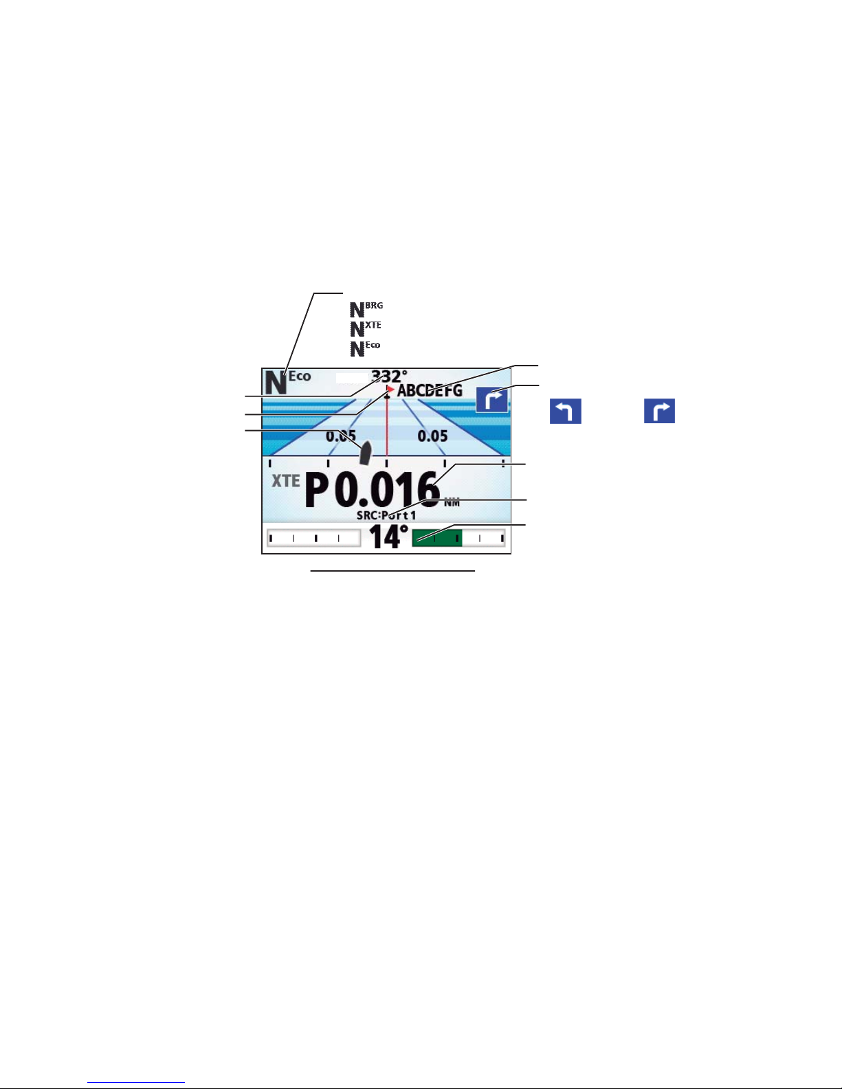
Display example: NAV mode
Direction to next waypoint
Waypoint name
Own ship mark
HDG T
HDG T
Set course or
XTE value
Data source
(Turn to STBD)(Turn to PORT)
Waypoint mark
Ship's heading
Analog indicator
or data box
Steering mode
㪑㩷[NAV Mode] = [Course]
㪑㩷[NAV Mode] = [XTE (Precision)]
㪑㩷[NAV Mode] = [XTE (Economy)]
2. STEERING MODES
2-6
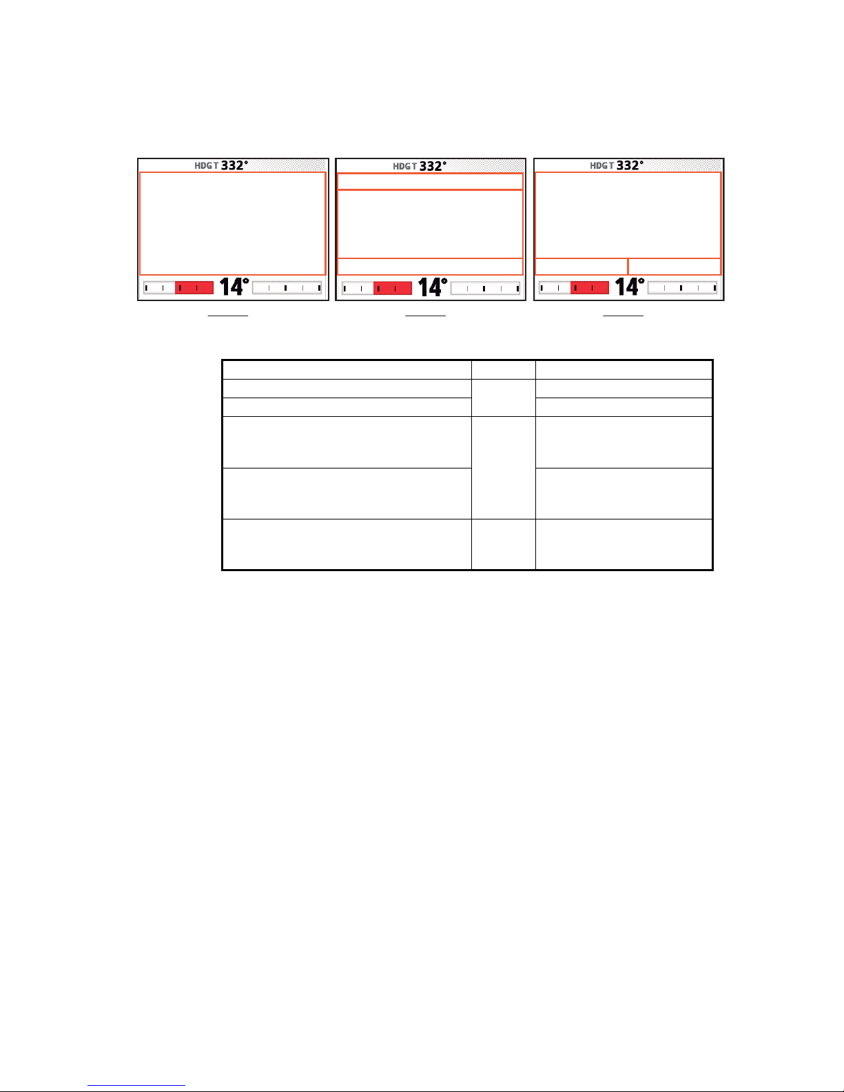
2.3.2 Sailing method for the NAV mode
Your vessel can go off course between waypoints in the NAV mode. This can occur
when, for example, a command is received from a remote controller. To return to the
course set, three methods are available: [Course], [XTE (Precision)], and [XTE (Economy)].
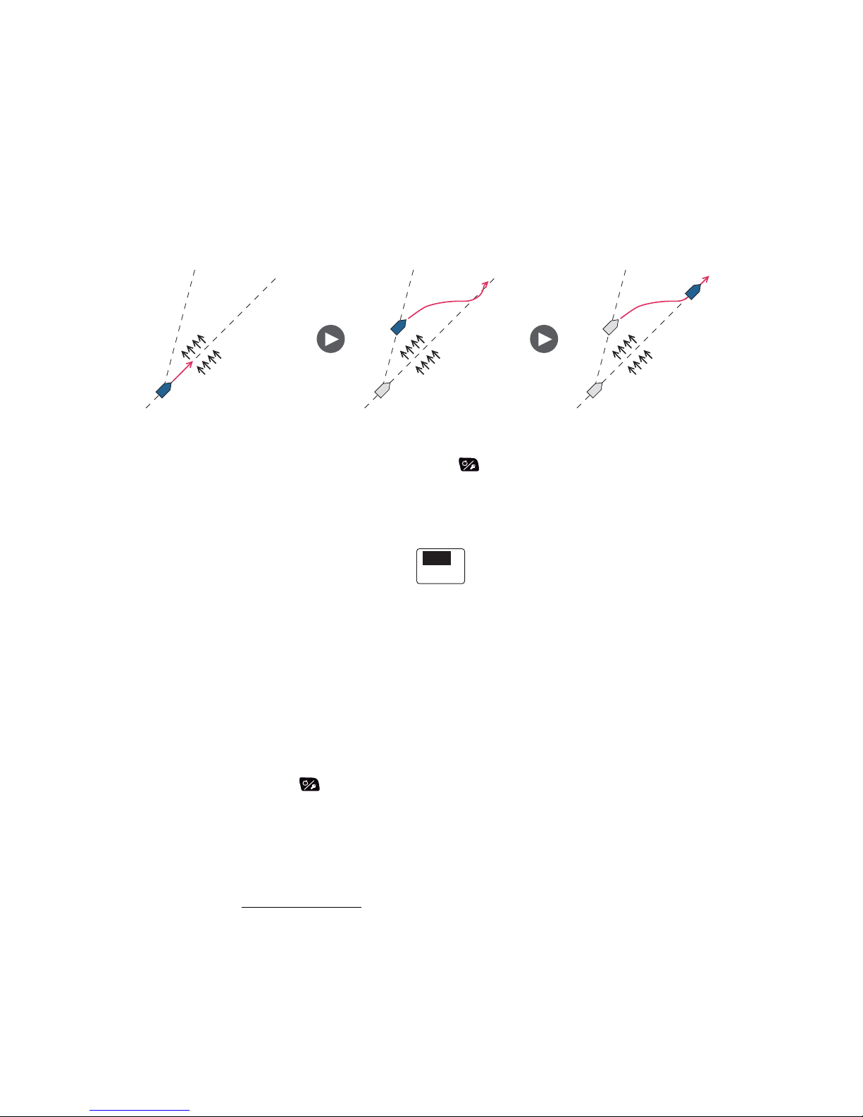
• [Course]: The NAVpilot calculates a new course according to your new position (after dodging, etc.) that takes you directly to your destination waypoint.
• [XTE (Precision)] and [XTE (Economy)]: The NAVpilot uses the XTE (cross-track error) value to steer the boat towards your ORIGINAL course before dodging. [XTE
(Precision)] provides for tighter course keeping, within 0.01 NM of the set course.
[XTE (Economy)] gives less tighter course keeping, within 0.03 NM of the set
course.
Note: [Course] is not available with Fantum Feedback
TM
.
Select the sailing method as shown below.
1. In the NAV mode, long press the key to show the menu.
2. Rotate the Course control knob to select the current setting for [NAV Mode] then
push the knob.
[NAV Mode] also appears on the [NAV Option] menu.
*: Not shown with Fantum Feedback
TM
.
3. Rotate the Course control knob to select an option then push the knob.
4. Press the key to close the menu.
Course line
([NAV Mode] = [Course])
XTE line
([NAV Mode] = [XTE(Precision)] or [XTE(Economy)])
Waypoint
Original course
Course*
XTE (Precision)
XTE (Economy)

2. STEERING MODES
2-7
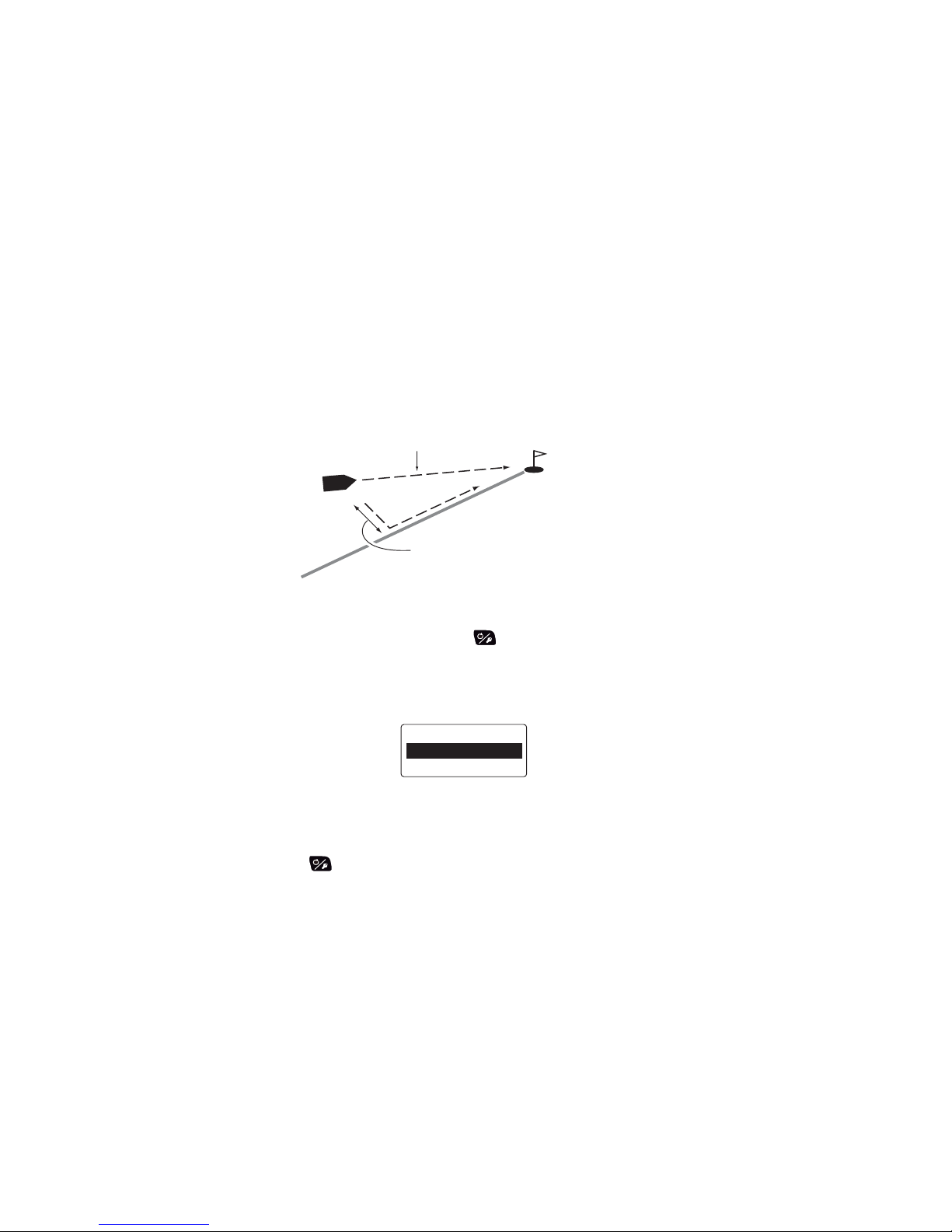
2.3.3 Waypoint switching method
When you arrive at a waypoint on a route in the NAV mode, you can switch to the next
waypoint automatically or manually.
Select waypoint switching method as follows:
1. In the NAV mode, long press the key to show the menu.
2. Rotate the Course control knob to select the current setting for [Waypoint
Switching] then push the knob.
[Waypoint Switching] also appears on the [NAV Option] menu.
3. Rotate the Course control knob to select an option then push the knob.
[Auto]: Switches to the next destination waypoint when your boat is within the arrival alarm area (set on the chartplotter). When your boat is within the arrival alarm
area, the buzzer sounds for five seconds and the message "WPT was changed."
appears.
[Manual]: Requires operator confirmation (pushing the Course control knob) before switching to the next waypoint. For manual switching, the NAVpilot sounds a
five-second alarm when the vessel arrives at the destination waypoint. The message "Push any key to return." appears. Push any key. Then, the message “WPT
was changed.” appears.
4. Press the key to close the menu.
Auto
Manual

2. STEERING MODES
2-8
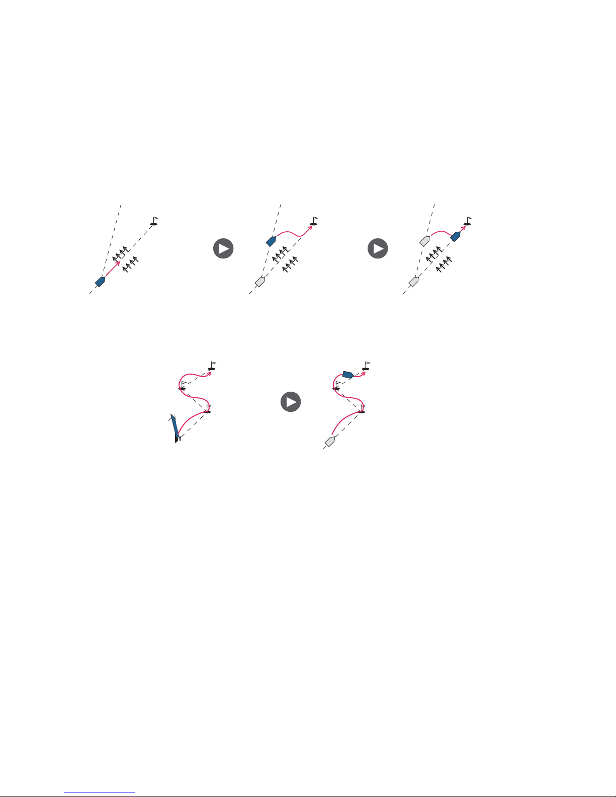
2.3.4 How to set the steering behavior of your boat after you arrive
to a waypoint
When you arrive to the last waypoint in a route, the FishHunterTM mode can be acti-
vated automatically to steer the boat according to the FishHunter
TM
mode preset. For
details of each preset, see section 2.6.
This function is not available with a sailboat.
To enable the FishHunter
TM
mode and set the steering behavior, do as follows:
1. In the NAV mode, long press the key to show the menu.
2. Rotate the Course control knob to select the current set-
ting for [After Arrival] then push the knob.
[After Arrival] also appears on the [NAV Option] menu.
For Fantum Feedback
TM
, only [GO Straight] and [Orbit to
STBD] appear.
• [GO Straight]: Cruise straight after arriving at the last
waypoint.
• [Orbit to PORT]: Orbits to PORT around waypoint.
• [Orbit to STBD]: Orbits to STBD around waypoint.
• [Figure Eight PORT]: Turns to PORT in a figure-eight pattern.
• [Figure Eight STBD]: Turns to STBD in a figure-eight pattern.
• [Square PORT]: Turns to PORT in a square pattern.
• [Square STBD]: Turns to STBD in a square pattern.
3. Rotate the Course control knob to select an option then push the knob.
4. Press the key to close the menu.
GO Straight
Orbit to PORT
Orbit to STBD
Figure Eight PORT
Figure Eight STBD
Square PORT
Square STBD
 Loading...