

Furukawa Unic URW370C4U Series, URW500C4 series, URW547C4U series Operation & Maintenance Manual

SERIES
SERIES
MINI-CRAWLER CRANE
HEAD OFFICE : Nihonbashi nishikawa Bldg, 5-3, Nihonbashi
1-chome, Chuo-ku, Tokyo 103-0027, Japan
MODEL
OPERATION
&
MAINTENANCE
MANUAL
OMURW37C4U50C4U547C4U201510A
PRINTED IN JAPAN

INTRODUCTION
Request to those who operate the crane
The operator’s manual describes correct operation methods, simple inspection, and service for the UNIC crane.
Be sure to read this manual carefully to carry out correct and safe operation of the crane.
Operate the crane after you have understood the contents of this manual.
Although we take all possible measures to ensure quality of the crane, you are requested
to contact our business offices, UNIC sales agents, or authorized service stations whenever you have anything you do not understand.
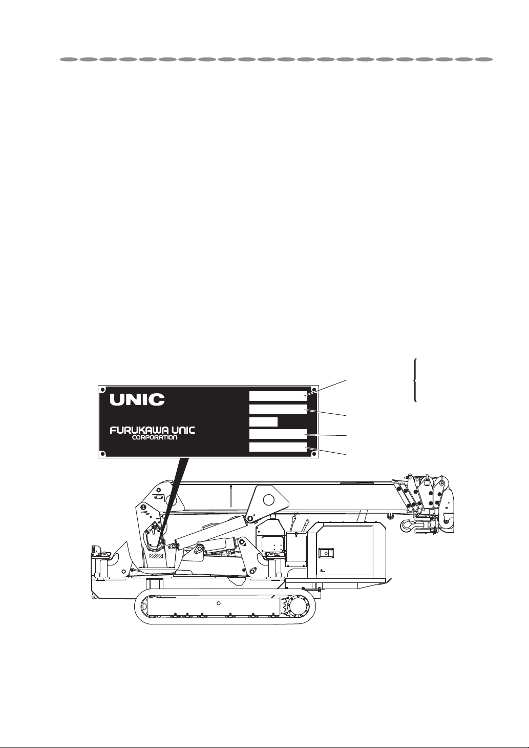
◆ For making inquiries
◆ When making inquiries, ordering spare parts, and requesting repairs, be sure to inform us
of the crane model, specification, serial number, and date of manufacture which are indicated on the name plate.
◆ Name plate of the machine is located at the side of column.
TOKYO JAPAN
MADE IN JAPAN
MODEL
SPEC.
CAPACITY
SERIAL NO.
CODE NO.
LBS
Crane model
Specification
Serial number
Code number
URW375C4U
URW376C4U
URW505C4U
URW506C4U
URW547C4U
0-1

TABLE OF CONTENTS
SETUP OF THIS MANUAL
URW370C4 series ………………………… 0- 4
URW500C4 series ………………………… 0- 5
URW547C4 ……………………………… 0- 6
1. FOR SAFETY OPERATION
Request to customers ……………………… 1- 1
2. SAFETY PRECAUTIONS ON
CARRIER OPERATION
Before operation …………………………… 2- 1
During operation …………………………… 2- 2
When loading and unloading ……………… 2- 4
After operation …………………………… 2- 4
3. SAFETY PRECAUTIONS ON
CRANE OPERATION
Before operation …………………………… 3- 1
During operation …………………………… 3- 2
After operation …………………………… 3- 4
4. DESCRIPTION OF CARRIER
EQUIPMENT
……………………… 4-1
5. DESCRIPTION OF CRANE
EQUIPMENT
……………………… 5-1
6. NAME PLATES
Description of name plates ………………… 6- 1
Stickers in detail …………………………… 6- 2
7. DEFINITION OF TERMS
Outrigger extension ………………………… 7- 1
How boom-sections are extended ………… 7- 6
Net rated load ……………………………… 7-10
Rated load ………………………………… 7-10
Lifting capacity …………………………… 7-10
Working radius …………………………… 7-10
Boom length ……………………………… 7-10
Boom angle ………………………………… 7-10
Lift above ground ………………………… 7-10
8. HOW TO REFER TO WORKING
RANGE CHART AND RATED LOAD
CHART
Working range chart ……………………… 8- 1
Rated load chart …………………………… 8- 2
9. DESCRIPTION OF EACH
CONTROL DEVICE
Overwinding alarm ………………………… 9- 1
Automatic stop for overwinding …………… 9- 2
Boom angle chart ………………………… 9- 4
Warning horn ……………………………… 9- 8
Retaining mechanism for slinging wire rope
Automatic stop for leaving minimum wire rope
(With wire rope retaining roller) …………… 9- 8
…9-8
10. HOW TO OPERATE CARRIER
Designation of each control lever
and its location …… 10- 1
Preparation before operation ……………… 10- 3
Precautions before operation
(air-bleeding procedures) … 10- 6
How to operate …………………………… 10- 7
How to Crawl ……………………………… 10-10
How to fasten carrier when in transportation
… 10-15
11. HOW TO OPERATE CRANE
Designation of each control lever
and its location … 11- 1
Preparation before operation ……………… 11- 3
Inspection before starting crane operation … 11- 4
Procedures to set up outriggers …………… 11- 6
How to operate boom for derricking
(raising and lowering) … 11-15
How to hoist and lower the hook …………… 11-16
How to telescope boom …………………… 11-18
How to slew boom ………………………… 11-20
How to store crane ………………………… 11-22
Procedures for storing hook ………………… 11-23
How to store outriggers …………………… 11-25
0-2

TABLE OF CONTENTS
12. U-WAVE, Radio remote control
device, (Option)
Request to those who operate the crane …… 12- 1
Safety precautions ………………………… 12- 2
Designation of each equipment …………… 12- 5
Inspection before crane operation ………… 12- 8
How to switch crane operation mode ……… 12-10
How to operate the crane through
radio control operation … 12-12
How to replace batteries of transmitter …… 12-35
Daily checks, trouble inspection …………… 12-38
13. MAINTENANCE AND
INSPECTION OF CARRIER
Inspection before operation ………………… 13- 2
Inspection and Maintenance which is to be carried
out every 250 hours or 3 months …………… 13-13
Inspection and Maintenance which is to be carried
out every 500 hours or 6 months …………… 13-21
Inspection and Maintenance which is to be carried
out every 1000 hours or 12 months ………… 13-23
Non-regular maintenance ………………… 13-29
Storage …………………………………… 13-34
Fitting safety covers ……………………… 13-35
Maintenance and inspection of engine ……… 13-35
14. MAINTENANCE AND
INSPECTION OF CRANE
Inspection before operation ………………… 14- 2
Cleaning …………………………………… 14- 3
Inspection of bolts mounting
slewing bearings …… 14- 3
Replacement of wire rope (for winding-up) … 14- 4
Replacement of expendable parts ………… 14- 8
15. WATER SUPPLY AND
LUBRICATION TO CARRIER
Precaution when carrying out filling
water and lubrication …… 15- 1
List of recommended lubricant …………… 15- 2
Filling water and lubrication chart ………… 15- 4
16. LUBRICATION TO CRANE
Precaution when carrying out lubrication …… 16- 1
List of recommended lubricant …………… 16- 2
Lubrication chart …………………………… 16- 3
Lubrication ………………………………… 16- 4
17. MAJOR SPECIFICATIONS
URW375C4U(5-section boom) …………… 17- 1
URW376C4U(6-section boom) …………… 17- 7
URW505C4U(5-section boom) …………… 17-14
URW506C4U(6-section boom) …………… 17-20
URW547C4U(7-section boom) …………… 17-26
Major specification
(Radio remote control device) for
URW370C4U, URW500C4U, URW547C4U
………………… 17-34
18. MODE INDICATOR LAMP
(CONTROL BOX)
Mode indicator lamp (Control box) ………… 18- 1
19. MEASURES TO BE TAKEN IN AN
EMERGENCY
……………………19-1
0-3
SETUP OF THIS MANUAL
SETUP OF THIS MANUAL
Crane covered in this manual have some difference in operation in accordance with the
specifications of with or without radio remote controller.
Difference in operation due to crane specifications is separately illustrated in this manual
for each specification.
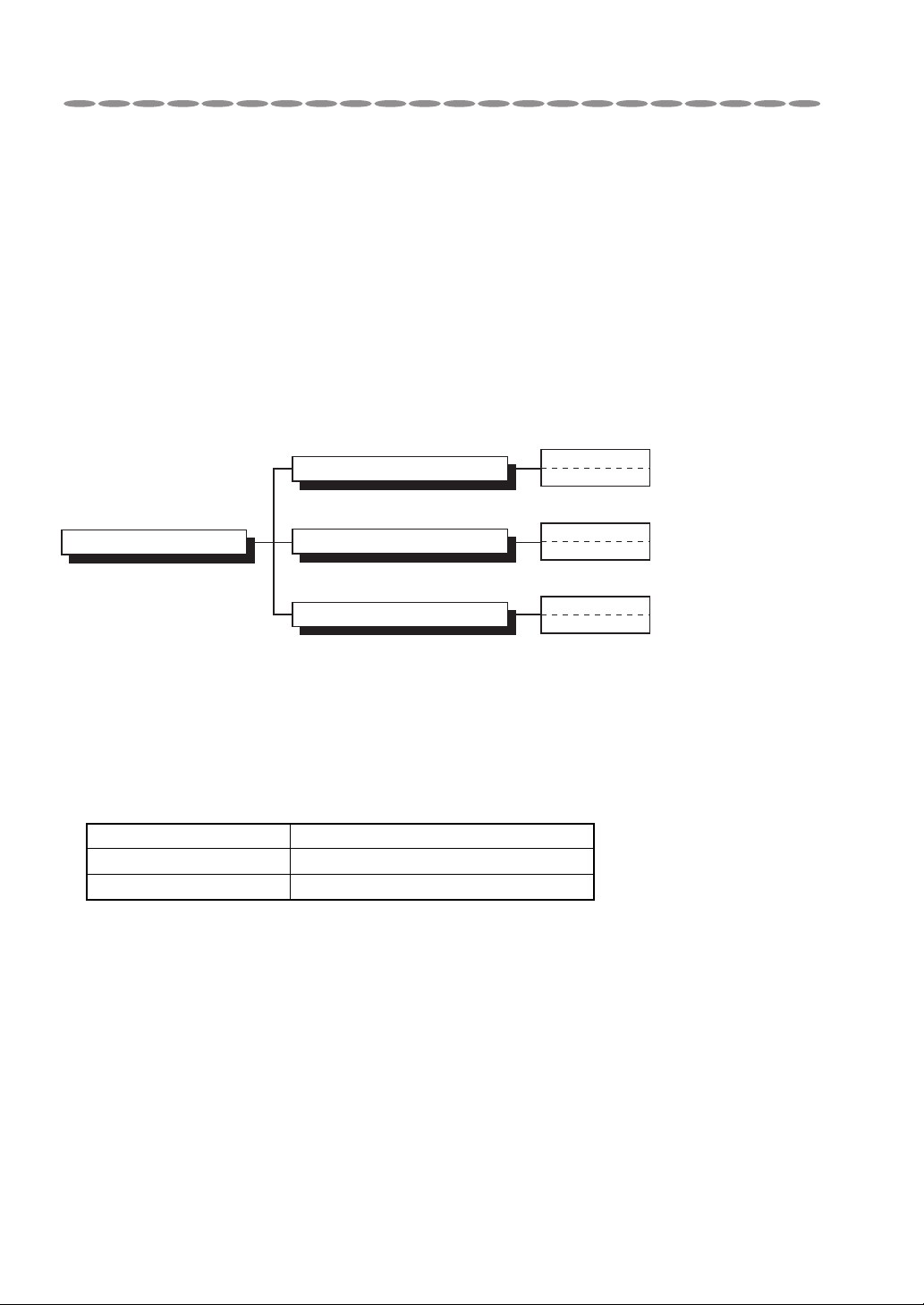
URW370C4 series
1. Designation of specification
Crane covered in this manual are roughly divided into three, the radio remote control
type, the cable remote control type and the manual control type.
URW370C4U
RS
URW370C4U
R
URW370C4U
URW370C4U series
With radio remote controller
With cable remote controller
Manual specification
2. Designation of model
URW370C4 series of crane model is to be designated according to the number of sections of telescoping boom.
(Model) Number of boom section
URW375C4 5
URW376C4 6
0-4
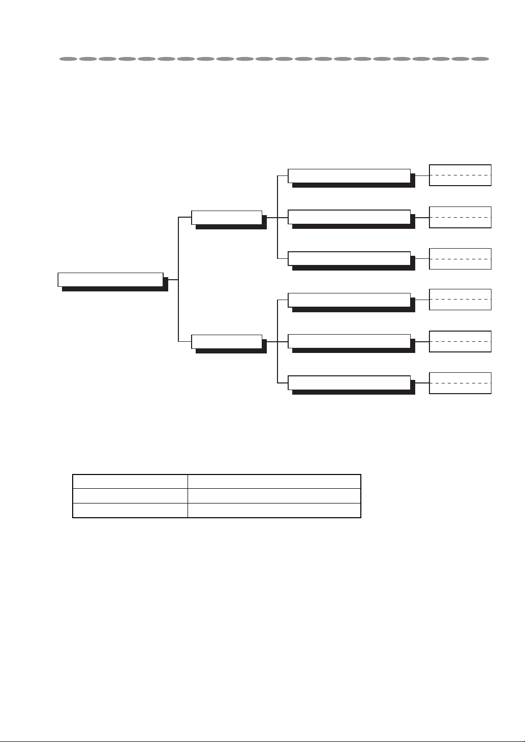
URW500C4 series
1. Designation of specification
Crane covered in this manual are roughly divided into two: short outrigger type and standard outrigger type.
URW506C4U
URW506C4U
URW506C4U
Standard type
With radio remote controller
With cable remote controller
Manual specification
URW500C4U series
URW505C4U
URW505C4U
URW505C4U
Short type
With radio remote controller
With cable remote controller
Manual specification
2. Designation of model
URW500C4 series of crane model is to be designated according to the number of sections of telescoping boom.
RS
R
RS
R
(Model) Number of boom section
URW505C4 5
URW506C4 6
0-5

URW547C4
1. Designation of specification
Crane covered in this manual are roughly divided into three, the radio remote control
type, the cable remote control type and the manual control type.
URW547C4U series
With radio remote controller
With cable remote controller
Manual specification
URW547C4U
RS
URW547C4U
R
URW547C4U
0-6

MEMO
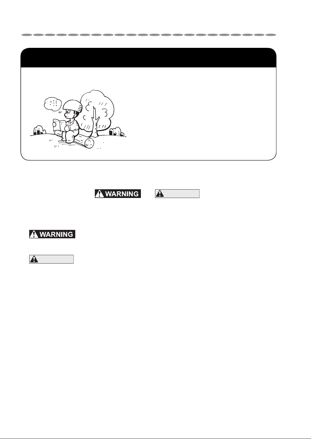
1. FOR SAFETY OPERATION
Observeallthesafetyregulations!
• Read preventive measures
against danger and cautions
stated in this manual for proper understanding.
• Most accidents related to the
crane occur due to operation,
maintenance, and inspection
which have failed in observing
basic safety regulations.
Request to customers
◆ Never failed to observe and
they are of great importance in safety and the crane operation.
…
Failure to observe this may invite an accident resulting in injury or death.
CAUTION
◆ Store this operator's manual where it is easily accessible to read it over and over again.
◆ Failure to observe the right operation and maintenance/inspection illustrated in
this manual may cause trouble in the crane and may invite an accident, and this
will not only shorten its service life but will impair safety in the crane operation.
Please remember, in such cases, that no warranty will be given even if the crane is within
valid warranty period.
◆ In order to prevent injury or death to crane operators and to those who stand close to crane
operating area due to operational mistake, caution plates are stuck on the crane.
You are requested to read them carefully.
◆ Do not alter the crane.
• If you want to make an alteration, contact with UNIC sales agent or an authorized service
shop.
…
Failure to observe this may cause damage to the crane.
CAUTION
described in the manual as
• UNIC does not bear any responsibility for troubles and /or accidents due to unauthorized
alteration.
1-1
2. SAFETY PRECAUTIONS ON CARRIER OPERATION
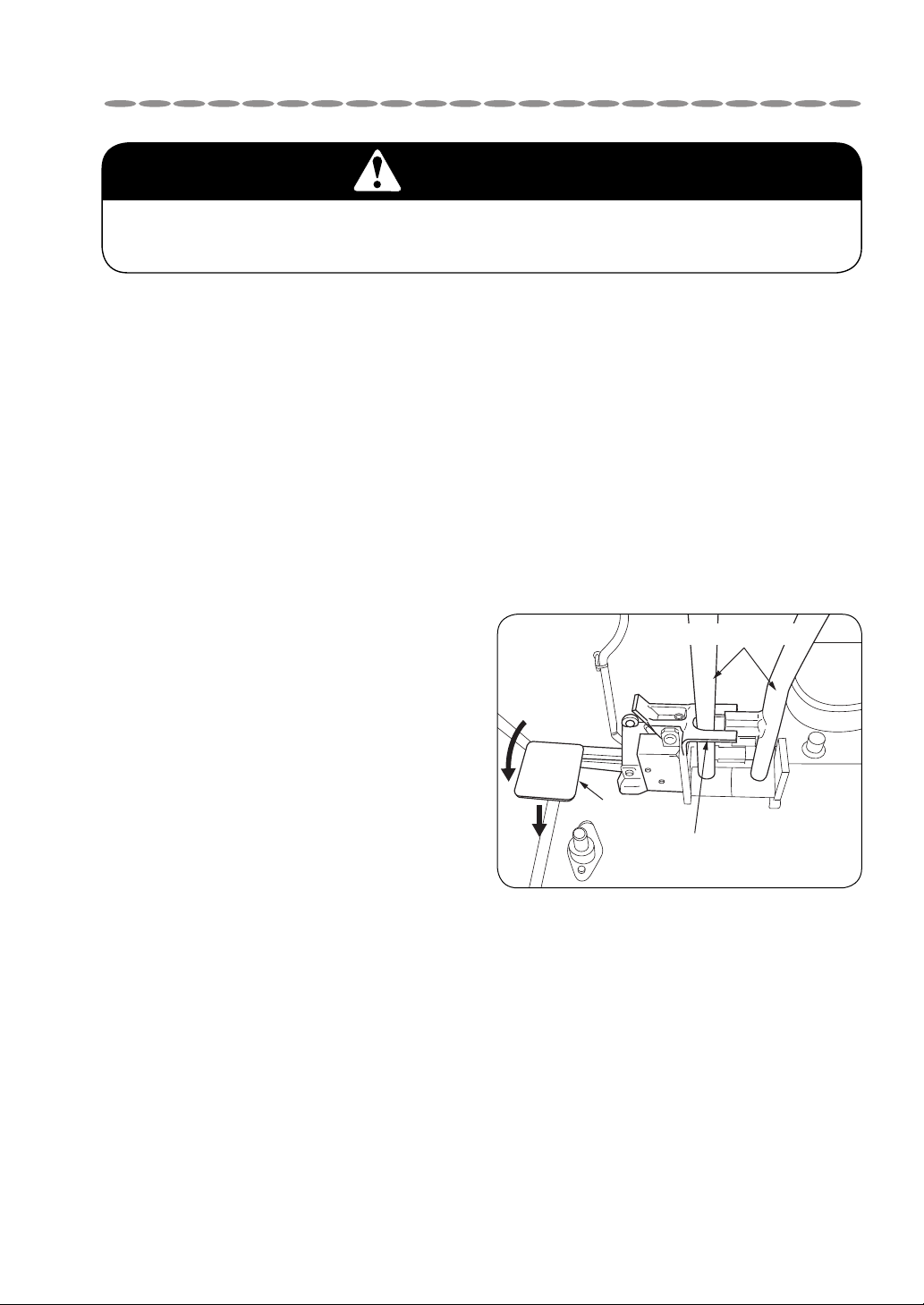
Pedal
Crawling
Interlock for crane-crawl
operation
Crawling lever
WARNING
Observe the cautions for securing safety.
Failure to observe the cautions may cause trouble or serious accident.
Before operation
Dress neatly and wear protectors such as
1
helmet, safety shoes, and gloves without
fail.
Do not wear baggy clothes and accessories
which can be caught by control levers and fittings, and oil-stained working clothes which
may catch fire.
Be sure to make inspection before oper-
2
ation and periodical voluntary inspection.
If found something wrong, repair it immediately.
The crane is prohibited to crawl on a
3
public road by the road traffic law.
Check that no safety covers have been
4
left removed.
It is very dangerous to start the engine,
to operate the crane with the safety cover
removed as the driving mechanism is
exposed.
When starting the engine in a small lim-
6
ited area or indoors, open the windows
and doors for well ventilation.
Poor ventilation may invite an exhaust gas
poisoning.
Shift the interlock for crane-crawl lever
7
to “Crawl” when crawling the crane.
Crane will not work by controlling crane
operation levers with the interlock for cranecrawl lever shifted to “Crawl”.
Be sure to stop the engine before refuel-
ing or supplying and changing lubricant.
5
A fire source such as smoking cigarette in
mouth is strictly prohibited.
Failure to observe this may cause a fire.
2-1
SAFETY PRECAUTIONS ON CARRIER OPERATION
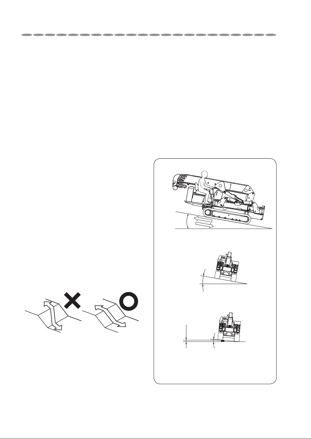
Less than
20°
Less
than
23°
Less than 10°
on the unstable road
Less than
10°
Less than
0.6ft
(170 mm)
Move forwards and backwards
(straight)
When driving over a gap of the step, there is a risk of tipping
over caused by vibration or a shock. Therefore, make sure
the gradient of carrier is less than 10°, or the gap of the step
is less than 0.6ft (170 mm). The driving speed should be
“Very Low Speed” and sudden turning is strictly prohibited.
Left/Right gradients
Drive over a gap of the
step with either left or
right side of the carrier
・
During operation
The machine employs particularly small
1
truck to facilitate working in a restricted space.
Since high performance crane is mounted on
the small truck, it has been built with a higher
center of gravity.
Take special care not to overturn the crane
when crawling on a unleveled ground.
When crawling the crane, be sure to put
2
outriggers in a condition of being stored
and store the hook.
Do not run the crane with a cargo hoist-
3
ed or without the crane being stored.
Special care must be taken to run the
4
crane slowly when making a quick turn
and crawling on a rough road.
10
11
at a higher position than the crane body.
12
as there is a risk of roll-over.
Do not make an abrupt stop and
start, and change a course on a slope.
When crawling up and down a
slope, operate the crane by standing
Do not operate the carrier on the
more steep slope than shows below,
When running over a bump, be sure
5
to slow down the crane and direct it
straight to the bump to avoid unnecessary
shock to the crane body.
When driven over an irregular road sur-
6
face or going up and down the slopes,
the carrier must get over the slope straight and
try not to give any shocks to it.
Be sure to use a foot-board to run over a
7
ramp of more than 0.5ft(15cm).
Crawl the crane with low (1st) speed
8
gear on a slope.
Be sure to use a pallet against the rub-
9
ber crawler when parking the crane on
a slope.
2-2
SAFETY PRECAUTIONS ON CARRIER OPERATION
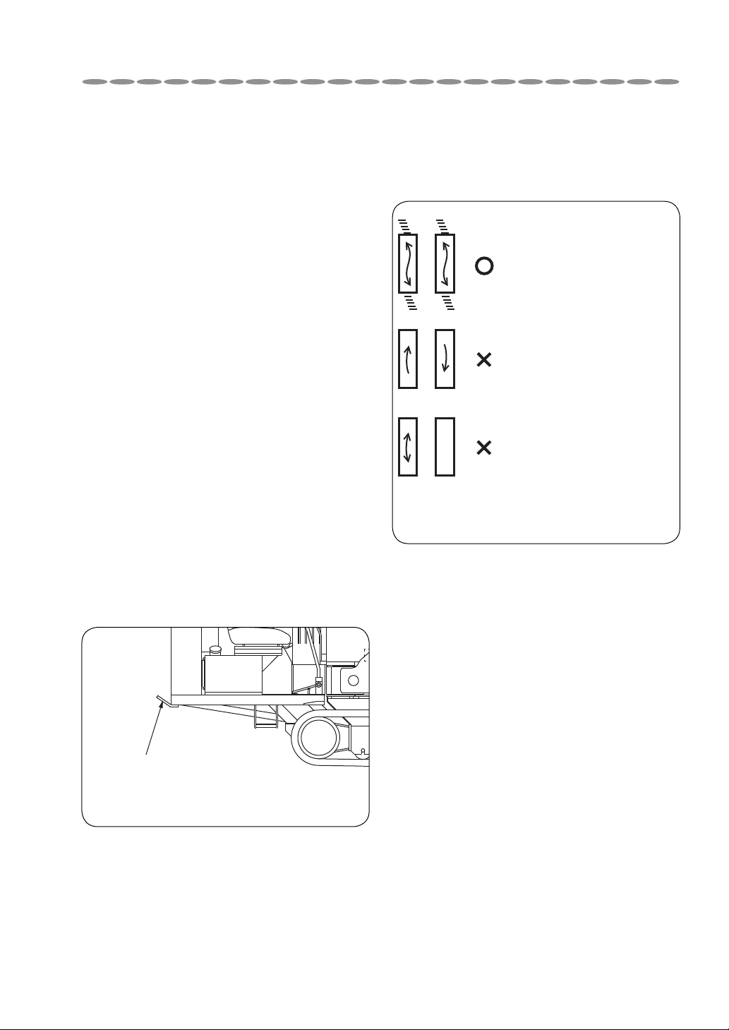
Hook holder
Do not run the crane over bumpy
13
rough solid rock, small broken stones, edges
of steel plate, steel bars for reinforcement,
scrap metals, and waste materials and on a
road such as in riverside where covered with
many stones which may remarkably shorten
service life of rubber crawler.
14
It may invite critical situation due to abrupt
swing or shift of center of gravity.
15
being spread.
It may cause a fire by heat of exhaust pipe or
exhaust gas.
16
body as a means of pulling a vehicle.
This may break the holder.
area, lying rocks with sharp edges,
Do not take an article or an animal
in the crane.
Do not park the crane over a place
where withered grass or straw are
Do not use the hook holder mounted in the rear side of the crane
To avoid rubber crawler damage.
17
Be sure to drive both sides
()
()
()
For the white (or gray) crawler, observe the
driving strictly in terms of its characteristics.
of crawler in the same
direction for making a turn.
Do not drive both sides of
crawler in the opposite
direction each other.
Do not drive only one
side of the crawler.
2-3

SAFETY PRECAUTIONS ON CARRIER OPERATION
When loading and
unloading
When loading and unloading the crane,
1
use a non-slip foot-board with a enough
capacity of strength, width, and length and
run the crane straight up and down at a very
low speed.
Changing direction of the crane on the footboard may cause the crane to fall off.
Stop the engine, apply parking brake,
2
and put drags to wheels to secure the
mounting vehicle when loading and unloading the crane.
Failure to observe this may cause the crane
to fall off because the vehicle shift while it is
being loaded and unloaded.
Work by following the instructions illustrated
in the sticker, “Loading and unloading procedures”. (Refer to page 6-6.)
After operation
Return the crawling lever and run the
1
engine at a low speed.
Shift the crawling lever to “Crane” posi-
2
tion.
Stop the engine and remove dirt and dust
3
stuck on the crane body.
Since dust stuck on the battery, electric wiring, and engine related components such as
muffler may cause a fire in particular, be sure
to remove it.
Cover the crane or store it in a storage
4
house to prevent it from being accessed
by unrelated persons such as children.
Cover the crane after heated sections have
been cooled off.
Putting a cover on while the crane body is
still hot may cause a fire.
Remove the starter switch key to store.
5
Disconnect a battery cable before the
6
crane is to be stored for a long period of
time.
Failure to disconnect it may cause a fire as
cables short-circuited by gnawing animals
such as rat.
Cable (-)
Disconnect
2-4
3. SAFETY PRECAUTIONS ON CRANE OPERATION
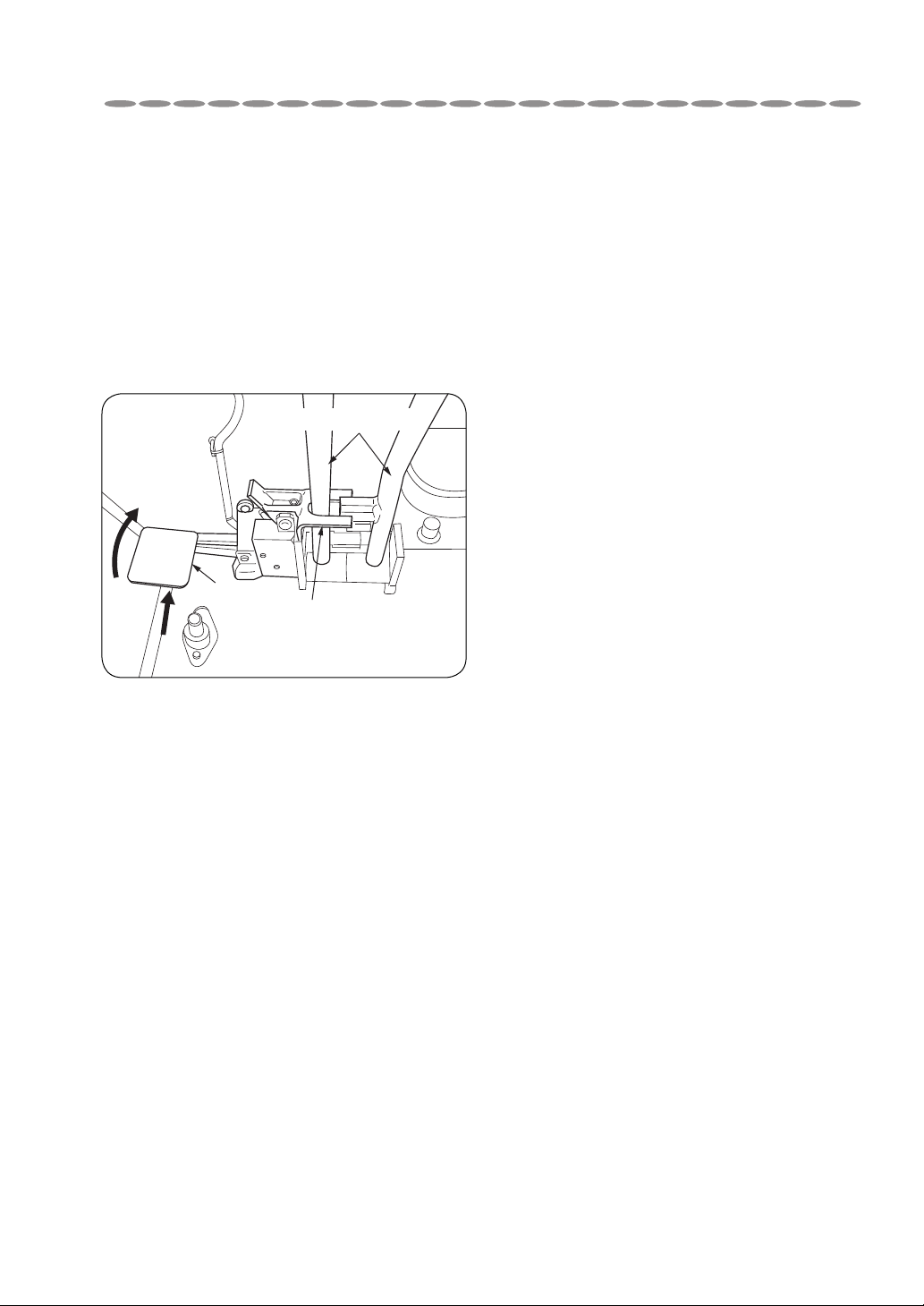
Pedal
Interlock for crane-crawl
operation
Crawling lever
Crane
Before operation
Be sure to make inspection before oper-
1
ation and periodical inspection for sling-
ing implements.
If a defective slinging implement is used, fall
of lifted cargo may result.
Shift the interlock for crane-crawl lever
2
to “Crane”.
Turn ON the overwinding alarm switch.
3
Make sure that each safety device is
4
always functioning properly.
Be sure to turn ON the overwinding alarm
switch before starting crane operation.
• When the crane is to be operated close
to the power transmission or distribution
line, contact in advance with a local power
company to make arrangements concerning safety for starting the crane operation.
• If crane operation close to the power transmission or distribution line is unavoidable,
be sure to secure safety distance from the
power lines.
List of target safety distance
Power transmission line
Voltage Safety distance (target)
500,000 volts 36ft(11.0m) or more
275,000 volts 23ft(7.0m) or more
187,000 volts 20ft(6.0m) or more
154,000 volts 17ft(5.0m) or more
66,000 volts 14ft(4.0m) or more
22,000 volts 10ft(3.0m) or more
Power distribution line
Voltage Safety distance (target)
6,600 volts 7ft(2.0m) or more
Do not operate the crane when wind
6
velocity exceeds 22mph(10m/sec). and/
or while thundering.
Crane operation while strong wind is blowing
can cause fall of a lifted cargo or overturn of
the crane as the boom and/or a lifted cargo
are hit by a gust of wind.
Keep a safety distance away from the
5
high-voltage power line to avoid an
electric shock.
• The crane is not electrically insulated.
• When the crane is operated near the power
transmission line or the power distribution
line, there may be a risk of electric shock
due to electric discharge even if a part of
the crane such as boom will not make a
direct contact with the power lines.
Pay attention that anyone except per-
7
sons concerned will not enter within a
working radius of the crane.
Take good care to carry out safety operation
by keeping a close watch around the working
area.
3-1
SAFETY PRECAUTIONS ON CRANE OPERATION
During operation
Make sure that the ground on which
8
outriggers are to be set up is solid and
firm.
When setting up the outriggers on an
unleveled ground or on a slope, be sure to
place a support (such as plank, steel plate
etc.) under the outrigger foot flanges to keep
the crane level.
In addition, when the crane is to be operated
on a soft ground, take the same measures to
prevent the outrigger foot flanges from sinking into the ground when a cargo is lifted up.
Lift up the crawler by approx. 2in.
9
(50mm)from the ground.
DANGER
BEFORE OPERATING THE CRANE
IT IS MANDATORY TO
SET UP ALL THE
OUTRIGGERS
Pay attention that the hook will not be
1
overwound.
Be sure to turn ON the “overwinding alarm
switch”.
• Remember that the hook is wound up
when boom is extending.
• If the hook hits against the boom top due
to overwinding of the hook, it may cause
damage to wire rope and the sheaves at the
boom top and may cause the fall of lifted
cargo.
Operate each lever slowly and smooth-
2
ly.
An abrupt lever operation with a cargo lifted
gives an excessive shock to the crane which
may cause damage or overturn to the crane.
Slew the crane at low speed.
3
Operation with the crane kept
10
cargo is lifted up.
Such operation can cause the crane to be
overturned.
11
outriggers fully extended.
12
13
leaning makes it unstable when a
In normal crane operation, be sure
to set up the crane level with the
Do not stand under or in front of the
hook when unhooking as it swings.
Do not try adjusting hydraulic
equipment.
Swing of a lifted cargo increases working
radius of the crane which may cause it to be
overloaded.
If the engine speed is too slow when
4
operating the crane, press the accelerator to increase it.
Crane operation with the engine (and pump)
running at low speed may cause a cargo
hoisted up to swing due to pulsation of
the engine.
This is not a malfunction but impairs smooth
control of the crane.
Overloaded operation is strictly prohib-
5
ited.
Crane operation with a load exceeding the
rated load hoisted may cause damage or overturn to the crane.
3-2

SAFETY PRECAUTIONS ON CRANE OPERATION
Pulling a cargo sideways, straight, or
6
obliquely is strictly prohibited.
These operation may cause slewing members, booms, columns, and derrick cylinder to
be damaged.
When a cargo to be lifted is detached
7
from the ground, stop lifting it up tem-
porarily to confirm safety.
• When a cargo to be lifted is detached from
the ground, stop lifting it up temporarily
to make sure that the cargo is kept horizontally, the crane maintains its stability,
and the rope slinging up the cargo is positioned properly.
Then lift it up again after making sure of
the safety.
• For lowering a cargo, stop lowering it
immediately before it touches the ground
then lower it again gradually.
Do not leave from operating position
8
with a cargo hoisted.
Lower a hoisted cargo onto the ground before
leaving from the operation site.
Do not get up on a cargo being hoisted.
9
This may cause a fall from the cargo being
hoisted.
Do not stay under a hoisted cargo.
10
Pay attention that wire ropes will
11
prevent ropes from being wound around the
drum irregularly.
• Operation such as paying out wire ropes
• Wind the first layer of rope firmly and
• Correct kinks of rope immediately with a
12
be lowered further than the work on the
ground.
When paying out wire ropes, be sure that
more than 3 turns of rope must always be left
on the drum.
13
176°F(80°C).
• Oil temperature is apt to rise easily if
• Excessive high temperature of hydraulic
not be paid out unnecessarily to
further with a cargo placed on the ground,
retraction and/or lowering boom loosen
the ropes to cause them irregular winding
which results in remarkable shortening
service life of the ropes.
regularly around the drum.
mallet.
Pay extra attention to underground
crane work in which the hook must
Stop crane operation when temperature of hydraulic oil exceeds
repeated operation of winding up and
down the hook, especially in a high lift, is
required.
oil damages high-pressure hoses and gaskets being employed to cause the oil to
spout out so that a scald may result.
3-3

SAFETY PRECAUTIONS ON CRANE OPERATION
After operation
Make sure that the booms, the outrig-
1
gers, and the hook have been stored
before crawling the crane.
Do not carry out maintenance and
2
inspection while temperature of either
hydraulic oil or gear oil is still high.
Temperature of both hydraulic and gear
oil is high immediately after crane operation so that accumulated high pressure still remains.
Removing filling cap, draining oil, or replacing oil filter while temperature is still high
allows hydraulic and/or gear oil to spout out
and a scald may result.
Since temperature on the engine and the
3
hood in the side is too high immediately
after crane work, touch them after they have
been cooled down.
3-4
17
19
8
10
6
14 7
9
521 4 3
14
18
17
11
12
16
20
13
URW505C4U
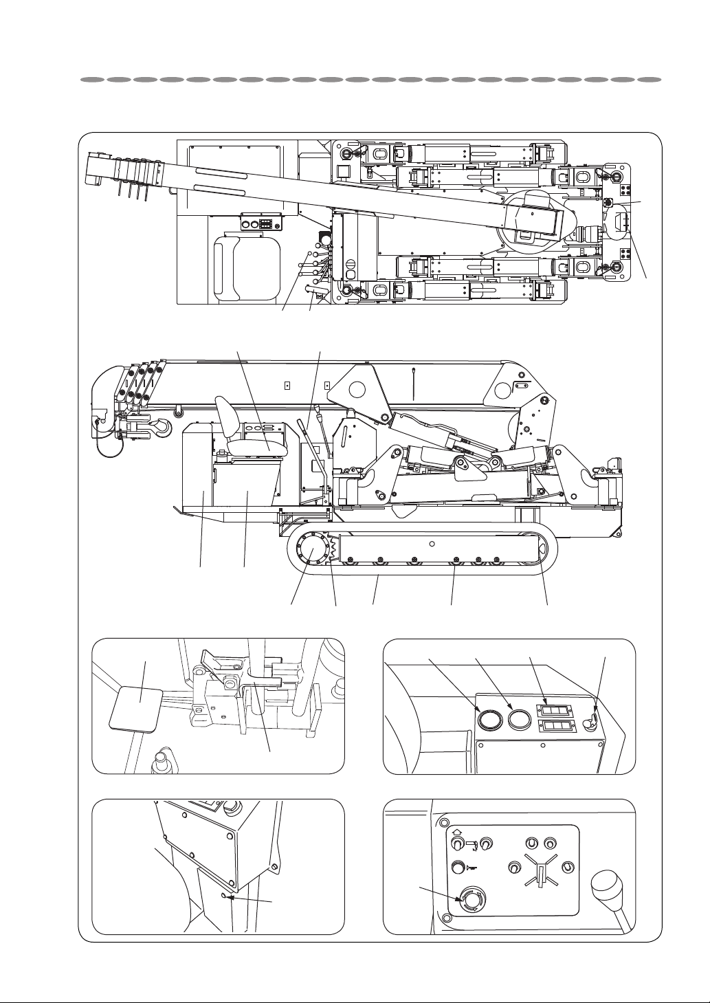
4. DESCRIPTION OF CARRIER EQUIPMENT
4-1
17
19
8
10
6
14 7
9
521 4 3
14
18
17
11
12
16
20
13
DESCRIPTION OF CARRIER EQUIPMENT
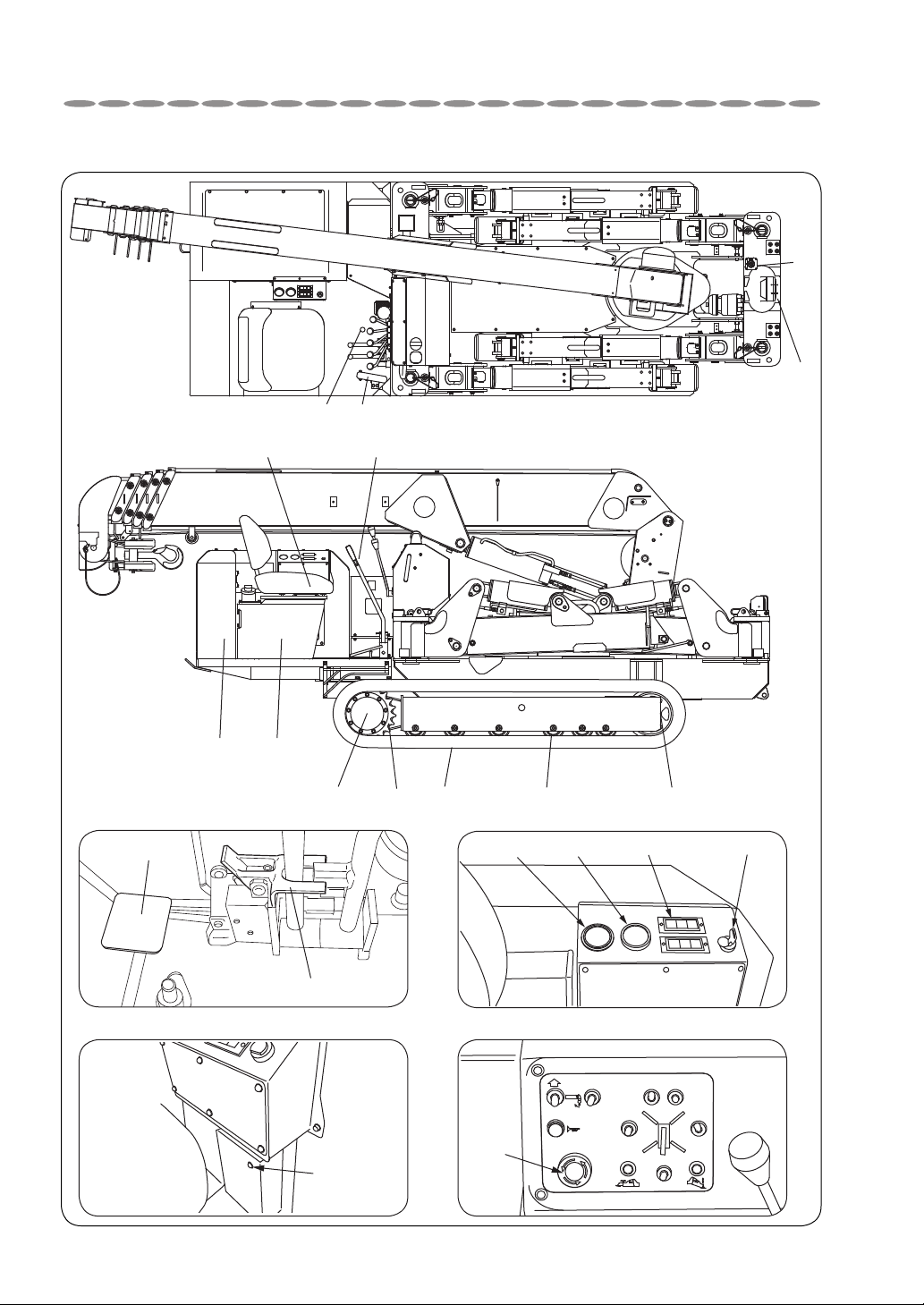
URW375C4U / URW376C4U / URW506C4U / URW547C4U
4-2

DESCRIPTION OF CARRIER EQUIPMENT
1. Rubber crawler
Cored bar and steel fabric(cords) are integrally
molded in the rubber which is of the same
quality as automobile tire.
2. Wheel sprocket
It transmits driving power to the rubber crawler to allow the crane to crawl.
3. Idle roller
This is a roller which gives a proper tension to
the rubber crawler.
4. Truck roller
This supports the weight of crane and rolls on
the rubber crawler.
5. Crawling motor
Hydraulic motor with reduction gears which
transmits driving power to the wheel sprocket
is built inside.
6. Crawling lever
This is to change crawling speed and direction.
7. Accelerator pedal
This is to control engine speed.
8. Driver's seat
This is a seat on which operator sits to operate the crane.
9. Fuel tank
This is filled with diesel oil.
10. Hydraulic oil tank
This is filled with hydraulic oil which is commonly supplied both to the carrier and to the
crane.
13. Fuel meter
This indicates a residual quantity of the fuel.
14. Interlock for crane-crawl operation
This allows the crawling levers to lock while
the crane is being operated and allows the
crane not to be operated by the crane control levers when it is crawling. This can be
switched by pressing “18 pedal”.
15. Button for selecting crawling speed
This allows the crane to crawl faster while it
is being depressed.
16. Warning lamp
The lamp lights to indicate that something is
wrong with each section.
17. Emergency stop (engine) button
Depression of the switch allows the engine
to stop and all the crane operation including
traveling stop functioning.
18. Pedal
It is used to release crawling levers.
19. Head light
20. Indicator lamp for High altitude
solenoid
The lamp lights when the solenoid operates at
an altitude of 2622 ~ 5500 ft.(800~1676m)
It allows the engine to decrease quantity of
jet.
11. Starter switch
This is a switch to start and stop the engine.
12. Hour meter
This indicates total engine running time.
4-3

MEMO
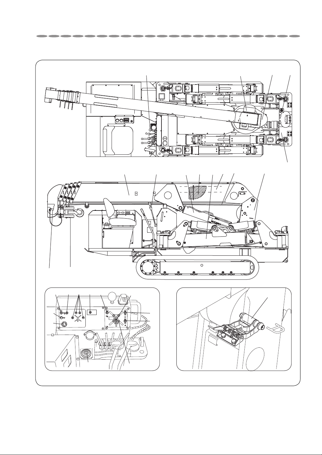
URW505C4U
5. DESCRIPTION OF CRANE EQUIPMENT
10
19
45
6
14
8
7
13
2
24
3
12
23
24
22
11
18 21 29
16
25
28
27
15
26
17
5-1

DESCRIPTION OF CRANE EQUIPMENT
URW375C4U / URW376C4U / URW506C4U / URW547C4U
10
19
45
6
14
8
7
13
2
24
3
5-2
12
23
24
20
22
11
181921 29
16
25
20
28
27
15
26
17

DESCRIPTION OF CRANE EQUIPMENT
1. Boom
It extends and retracts by hydraulic cylinder
and the hook is suspended from its top.
2. Column
This is a vertically mounted member on the
crane in which boom, winch, and derrick cylinders are installed.
The column can be turned by slewing device.
3. Frame
This is fixed on the vehicle to support the column and outriggers.
4. Hoist winch
This is a device which rotates the wire drum
by hydraulic motor to hoist up and down a
cargo via wire ropes.
5. Slewing device
This turns the column by hydraulic motor.
6. Derrick cylinder
This raises and lower the boom.
12. Overwinding alarm
When the hook comes close to the boom top,
this makes an alarm to warn that wire ropes
are to be overwound.
13. Wire rope
14. Boom angle chart
This can read the working radius value corresponding to extended length of the boom and
its raised angle.
15. Automatic stop for leaving mini-
mum wire rope (With wire rope
retaining roller)
This is a devise to restrict slackening of
wire rope on the drum which allows to stop
unwinding automatically when remaining
wire ropes on the drum come close to 3 turns.
16. Level
This an instrument for checking horizontal
plane of the crane body.
7. Telescoping cylinder
This extends and retracts sections of boom.
8. Outrigger
This supports the crane to maintain its stability while it is operated.
9. Crane operating levers
Respective levers control raising and lowering boom, hoisting a cargo up and down, telescoping boom, and slewing boom.
10. Outrigger operating levers
This lever controls outriggers.
The outrigger control switch (section 20)
selects each movement of extension and
retraction.
11. Hook
17. Voice switch
This switches ON and OFF the voice message.
18. Operation mode switch
This selects crane operation mode and outrigger operation mode.
19. Outrigger vertical/horizontal selec-
tor switch (URW505C4U exclude)
This switches extension/retraction control of
vertical cylinder for outriggers and of inner
boxes.
20. Outrigger vertical/horizontal lamp
(URW505C4U exclude)
The lamp indicates to which side the outriggervertical/horizontal selector switch has
been thrown.
5-3

DESCRIPTION OF CRANE EQUIPMENT
21. Outrigger control switch
This selects extension/retraction of each outrigger of four (4).
Simultaneous extension and retraction of outriggers can be impossible.
22. Hook storing switch
Turning the switch to the storing position
allows the hook to be stored.
23. Horn switch
Depression of the switch allows the alarm
horn to sound.
24. Emergency stop (engine) switch
Depression of the switch allows the engine
to stop and all the crane operation including
traveling stop functioning.
25. Automatic stop for overwinding
reset switch
When the crane cannot to be operated due
to a fault in function of automatic stop for
overwinding, turning the switch to reset side
releases the automatic stop for overwinding
device.
29. Mode selector switch
This switches between radio remote control
mode and manual operation mode.
26. Head light switch
Turning the switch ON allows the head light
to light.
27. Boom storage monitor lamp
The monitor lamp lights when the boom has
been stored.
Outriggers can be operated only when the
monitor lamp lights.
28.
Outrigger monitor lamp (extension)
When turning outriggers manually from their
stored positions and set pins have fully been
inserted, the lamp indicating extension of outrigger lights.
Outriggers cannot be operated unless all the
four (4) pins have been inserted.
5-4
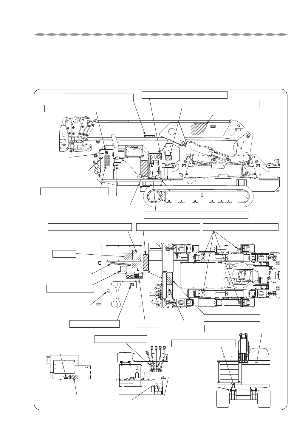
6. NAME PLATES
Caution, Crawling
Selector, Crawling/Crane
Caution, Storing hook
OR selector valve
Outrigger buzzer
Caution, High temperature
Boom raius indicator
Caution, High temperature
Caution, Mode indicator lamp
Loading and unloading procedures
Caution, Slewing boom
Mass of
crane body
Boom storage
Preparing crane operation
and Storing hook
Diesel fuel
Lifting up position
of crane body
Hydraulic oil
Outrigger mode
Chart of rated load
Caution, Radio controlled operation
Caution, Battery
Caution,Oil level check
Caution, Watch-your-foot
ì²
Emergency operationCaution, Outrigger operation
Working range
Caution
Caution
Description of name plates (Stickers)
The machine is provided with stickers indicating caution (framed in box ) and specifications
as shown in the figure below, and in addition to that there are stickers showing control levers,
switches, and instructions for lubrication.
6-1
NAME PLATES
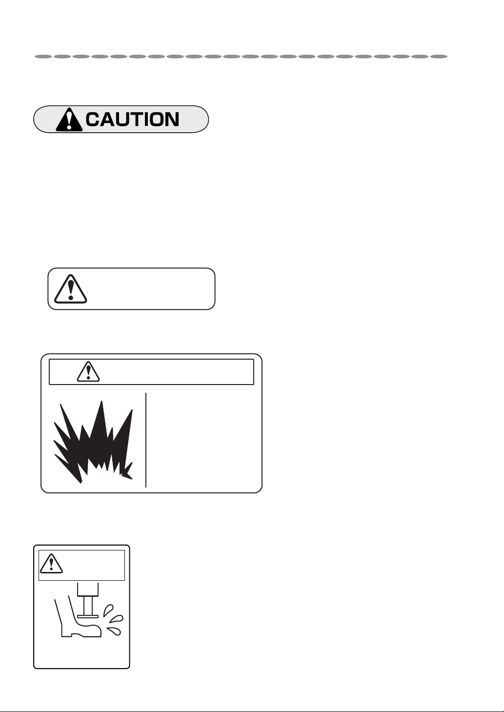
094383140
CAUTION, BATTERY
Wrong handling of battery may cause
to catch fire leading to explosion.
Do not make it short-circuiting,
sparking, and bring close to a fire.
In addition, you may be blinded or
burned by battery electrolytic solution.
When your eye, skin, or clothes was
stained with the solution, wash it away
with plenty of water immediately.
In case where the solution entered into
someone’s eye accidentally, see a
doctor to receive treatment after
washing it with water.
Stickers in detail
• Always keep the stickers clean so that they can be read easily.
• If any of the stickers has come off, stick it again or replace it with new
sticker.
• When ordering stickers, specify the part number shown at the bottomright of the sticker concerned.
Sticker [HIGH TEMPERATURE]
CAUTION, HIGH
TEMPERATURE
Sticker [BATTERY]
Sticker [WATCH-YOUR-FOOT]
Mind your
feet
Pay attention to your
feet when extending
outriggers.
6-2
094383110
NAME PLATES
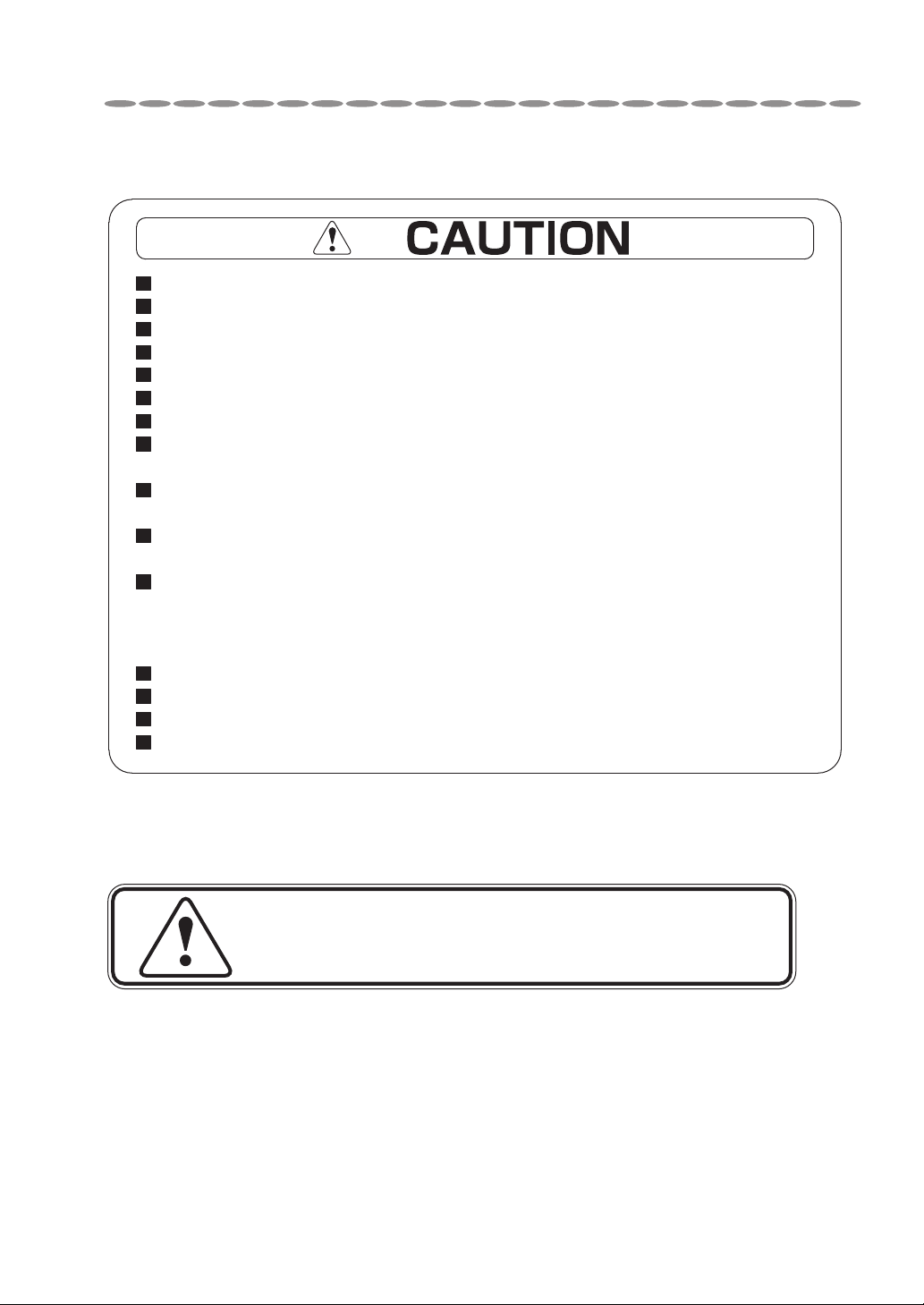
Sticker [CAUTION]
Carry out operation after you have read the instruction manual carefully.
Confirm safety around the crane before starting operation.
Be sure to carry out inspection and maintenance before starting operation.
Be sure to stop power (engine,power source)before inspection and maintenance.
Carry out inspection and maintenance of engine after it has been cooled down.
As the engine heats up, pay attention to prevent fire,always checking the surrounding area.
Set up the crane flat and even by referring to a level.
Load indicator reads the crane capacity when the crane has been set up on the level and solid ground.
By referring to the reading of loadmeter,never try operating the crane overloaded.
When lifting up a cargo exceeding the rated load, the crane may be in danger of overturn.
Operate the crane by keeping to the rated load.
Do not travel with a load lifted and operate the crane without outriggers extended
which are very dangerous.
Operate the crane with the outriggers extended and with the truck raised
by approx. 2in above the ground.
Operation without the truck raised may damage the truck and operation
with truck raised too high is dangerous so that it is strictly prohibited.
Keep an appropriate distance between the boom top and the hook while extending the booms.
Simultaneous operation for extension and retraction of outriggers will not be possible.
Store the hook securely before traveling.
Be sure to turn OFF the key switch after crane operation has been completed.
09TV81061-W546C1UR
Sticker [CAUTION SLEWING BOOM]
CAUTION SLEWING BOOM
B-524360
6-3
NAME PLATES
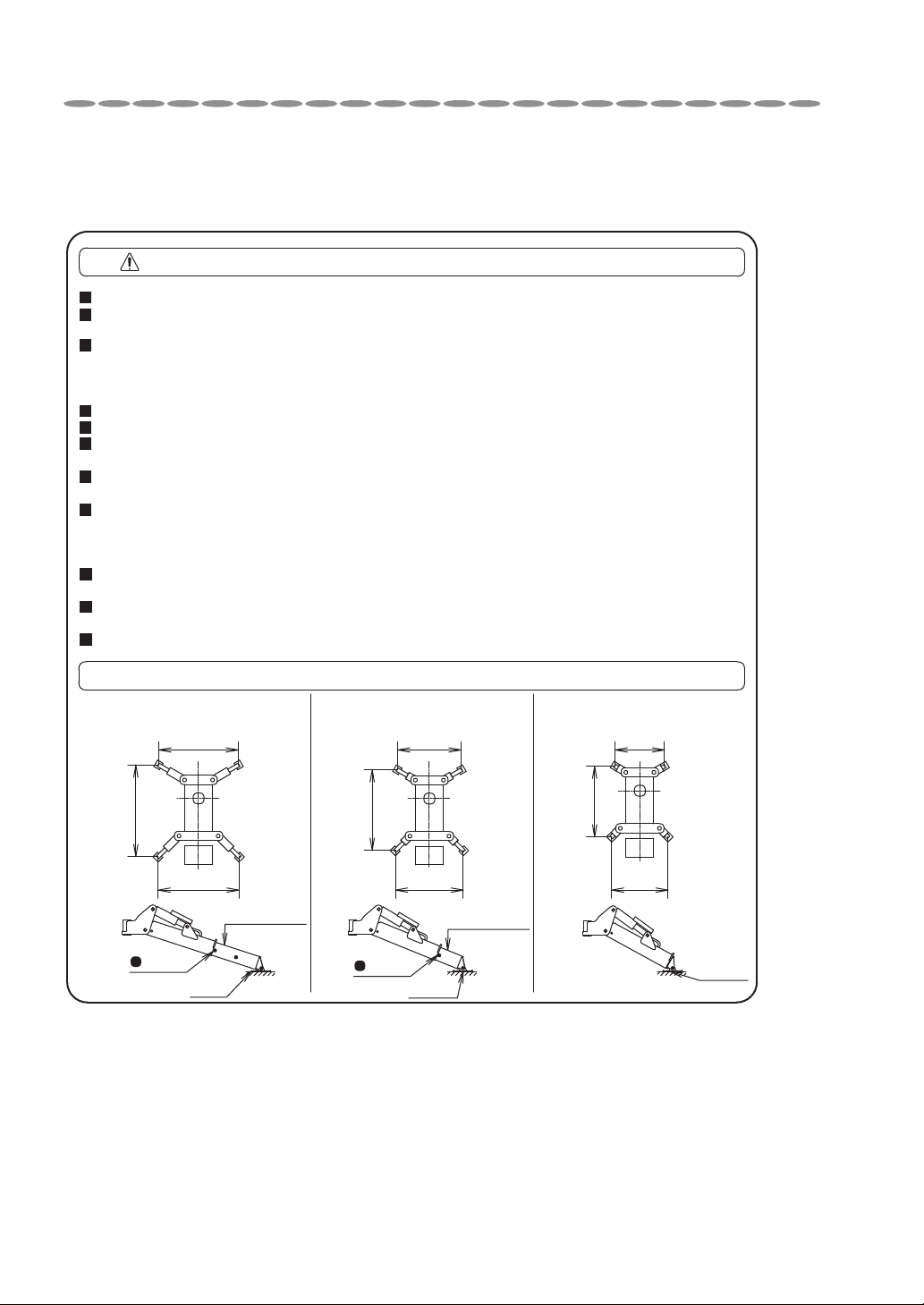
Sticker [POINTS TO NOTICE IN HANDLING OUTRIGGERS]
URW505C4U exclude
CAUTION OUTRIGGER OPERATION
When operating the crane, be sure to use outriggers to keep the crane body to be level.
Set up the outriggers on a flat and solid ground and in principle, operate the crane
with the outriggers fully extended.
When extending outriggers halfway, align the inner box extended either with the
halfway, or the minimum extension according to the “arrangement of outrigger extension”
and operate the crane each under the halfway or the minimum capacity specified in the
rated loads.
Do not extend vertical cylinder and inner box with the outriggers retracted.
Retract vertical cylinders before the stored outriggers are to be rotated.
Outriggers may become hard to be rotated when the floats touch to the supports
mounted lower side.
When setting up outriggers, be sure to touch them to the ground with vertical
cylinders after each inner box has been extended.
When swinging the boom with a cargo lifted up, stability of the crane is different
in the cargo lifted in front and rear and on the right and left.
Operate the crane with the working radius as short as possible and paying attention
that it will not to be overturned.
When storing outriggers, be sure to retract the inner boxes to their extremes after
each vertical cylinder has fully been retracted.
When outriggers are to be extended or stored, be sure to insert the pins so that
outriggers may not be rotated unexpectedly.
Be sure to store the outriggers before travelling.
ARRANGEMENT OF OUTRIGGER EXTENSION
Outriggers extended to maximum
Front
14.6ft
15.0ft
14.3ft
Rear
Inner box
Mark
(2nd)
Float
Outriggers extended halfway
Front
12.5ft
13.6ft
12.5ft
Rear
Inner box
Mark
(1st)
Float
Outriggers extended to minimum
Front
10.3ft
12.1ft
10.5ft
Rear
09VL81040-W376C1UR
Float
6-4
 Loading...