

Page 1
LED HDTV19"
Model: FEHS19H3A
USER’S MANUAL
Page 2
Safety Information
Warning
To prevent fir e an d/ or e le ct ri c shock, do not use this plug with an exten si on
cord, rece pt ac le o r ot he r ou tlet unless the blades can be fully i ns er te d to
preven t bl ad e ex po su re . Do n ot expose this appliance to rain or m oi st ur e.
AVIS RISQUE DE CHOC ELEC TRIOUE/NE PAS OUVRIR
Important Safety Instructions
Read the se i ns tr uc ti on s.
Keep these i ns tr uc ti on s.
Heed all w ar ni ng s.
Follow a ll i ns tr uc ti on s.
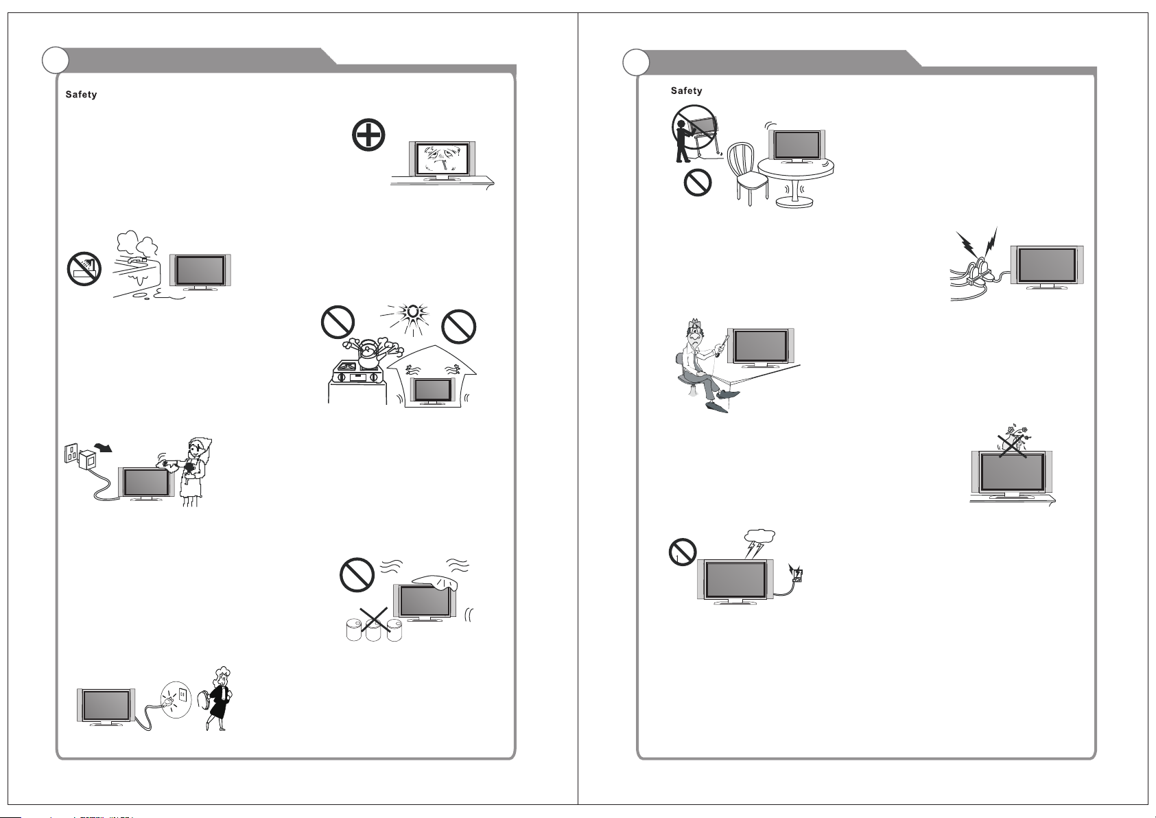
Please , un pl ug t he TV power co rd w he n th e fo ll ow ing conditions occur:
-When ther e is a t hu nd er st or m (Please, pull out the power cord an d an te nn a) .
-When clea ni ng t he TV set.
-When the TV set is not used for a lon g ti me .
Do not use cor ro si ve d ep ur at ive when cleaning the TV set.
Do not put the TV set under direct s un li gh t or n ea r he at.
Do not put a hea t so ur ce , su ch a s a ca ndle or heater, on top of or near the TV set.
Leave pl en ty o f sp ac e (a t le as t 10cm) around the TV set for ventilation.
Place the TV set away from where i t ca n be r ui ne d by r ai n or water (such as near a
window ).
Don't put a co nt ai ne r wi th l iq uid (such as a vase) on top of the TV set.
Do not move th e TV set when the powe r is o n.
Do not touch , pu sh o r sc ra tc h th e surface of the TV se t wi th hard materials or items.
When TV surfaces are dirty, please use a wet cotton c lo th o r so ft c lo th w it h noncorrosiv e cl ea ne rs t o cl ea n it carefully. Don ´t use acetone, toluene or alcohol to
clean the TV set.
Be aware and car eful of moisture, whi ch can damage inner electronic components.
Whe n condensed moisture i s pr es en t, t he TV scre en m ay a pp ea r bl ur ry or spotty.
It is recomm en de d th at a t ec hn ician install the TV set on a wall, if such placement is
desire d.
An incorre ct w al l in st al la tion will be unsafe and hazardous .
Do not let child ren clim b on or play around the TV set to avoid falls, collis sions,
damages and inju ries.
Do not hit the TV panel with hard ob je ct s to p re ve nt d amages.
Do not cover t he TV set with blank et s or o th er o bj ec ts when it is connected to a
power so ur ce t o pr ev en t ov er heating and fire.
Batteries shall not be exposed to excessive heat such as sunshine, fire or the like.
Mains pl ug i s us ed a s di sc on nect device from the mains, the disco nn ec t
device s ha ll r em ai n re ad il y operate.
Appara tu s wi th c la ss I c on st ruction shall be connected to a mai ns s oc ke t
outlet wit h a pr ot ec ti ve e ar thing connection.
Page 3
Important Safety PrecautionsImportant Safety Precautions
Please , im me di at el y pu ll o ut the AC power
plug from ad ap te r if t he re i s an a bnormal
sound or sme ll o r th e LE D TV has sou nd
but no pictu re , an d co nt ac t af ter sales
suppor t.
The LED TV should be kept free fro m ra in ,
moisture a nd d us t to p re ve nt e lectrical
shock and sh or t ci rc ui ts . Do n ot cover the
ventil at io n op en in gs w it h table clothes,
curtains , ne ws pa pe rs , et c.
The LED TV should be k ep t fr om h ig h
temperat ur e heating s ources or dire ct
sunlig ht . Good ventilation is re qu ir ed.
Allow 10 cm. be tw ee n the LE D TV and
other appl ia nc es o r bu il t- in cabinet walls.
When y ou wipe the fr on t cabinet, please
make sure th e p ow er plug is pu ll ed out and
use a soft, dry, lin t-free c lo th and h an dl e it
with care. Do not re pe at ed ly wipe t he panel,
nor scrape , ta p or s tr ik e th e pa nel with a hard
object.
Do not pla ce t he L ED TV on an unstab le
surface.
Do not place the power cord or oth er ca bl es
across a walkway in c as e it is tr am pl ed on. Do
not overload th e power c or d or power soc ke t.
When the pow er p lu g is u se d to d is connect and
connec t the device, it should easily into the
power so ur ce .
Do not di sa ss em bl e the back co ve r, as it
contains h ig h vo lt ag es i ns ide and will cause
electric sh ock. Only q ua li fi ed professionals
should conduct interna l adjus t m e n t s ,
maintena nc e, a nd c he ck s.
The T V set should not be s ub je ct ed t o
water droplets, vapor, or splash. This
equipm en t sh ou ld n ot b e pl ac ed on objects
filled with l iq ui ds . D o not p lace fl am e
sources, s uc h as lit candles, o n or near the
LED TV. P le ase, pull out the pow er plug
and contact a ft er sale s support if t he re are
abnorm al o bj ec ts o r wa te r in t he TV.
Do n ot wipe t he LED TV w ith any p etrol,
chemical o r al co ho l ba se d so lvents as it
will l ea d to product damage o f th e panel
and cabi ne t.
When the tel ev is io n re ce iv er is not used for an
extended p er io d of t im e, i t is a dvisable to disconnect
the AC powe r co rd f ro m th e AC ou tl et .
The MAINS pl ug o r an a pp li an ce c oupler is used as the
discon ne ct d ev ic e, The dis co nn ec t de vi ce s hall remain
readil y op er ab le .
Pull out the p ower co rd an d a nt en na ca bl e
during e le ct ri ca l st or ms s o the LED TV i s no t
damage d by ele ct ri ca l s ur ge s. Ke ep al l
people away f rom th e antenna cable d ur ing
electric al s to rm s.
Page 4
Table of Contents
Introduction
Features
Specifications
Accessories
General Description
Overview of front and side panel
Overview of back panel
Overview of remote control
Installing Batteries in the Remote Control
Install LED SET
2
3
4
4-7
4
5
6
7
8
Introduction
Features
W arnings
l TV adopts TFT LED display screen
l HDTV Compatible( 480p,720p, 1080i, 1080p)
l Support American TV Standard 8VSB/Free 64/256QAM,NTSC System, ATSC System
l Connect to computer directly to realize TV/monitor combo.
l Zero X radiation complies to green environment protection requirement
l Advanced Chroma Processing
l Closed captioning/PARENTAL LOCK
l SAP/STEREO/MONO; ATSC.
l HDMI input
l USB input (for factory use only)
External Connection
Connecting VCR
Connecting DVD Player/Set-Top Box
Connecting DVD Player/Set-Top Box via HDMI
Connecting Amplifier/DVD Home Theater
Connecting PC
Supporting signals
OSD Menu Operations
BASIC OPERATION
CHANNE L
PICTURE
AUDIO
TIME
SETUP
LOCK
Troubleshooting
Picture defects and the reason
9
9
10
11
12
13
13
14
14
14
15
15
16
16
17
19
20
Input terminals used for external equipment connection
One computer VGA/PC inpu t
One AV input
One L/R output
One Earphone output
One Component input
One ANTENNA jack
One PC Audio input
One HDMI input
One USB for factory use only
1
2
Page 5

Introduction
Specifications
W arnings
Model
Color active matrix LED display
FEHS19H3 A
1366X768
Fine digital control
Accessories
Please make sure the following items are included with your LED TV. If any items are
missing, contact your dealer.
Remote Control &
Batteries (AAAx 2)
Owner’s
Instructions
Warranty card
Power supply
AC 100-240V 50/60Hz
NTSC System, ATSC System
Antenna: 2~69; Cable: 1~135 (Analog: 1-125,
Digital: 1-135)
NTSC3.58
75W (Unbalance)
2 x 5 W
DC 3V (Two AAA size batteries)
32 W
18.0 x 1.8 x 11.9 inch
o
0C-40C
o
Note:
Design and specification modification maybe made at any time without
prior notice; all data and dimensions are approximations.
General Description
Overview of front and side panel
SPEAKER
REMOTE CONTROL SENSOR
Aim the remote control towards this
spot on the TV.
POWER INDICATOR
Green: In power on mode.
Red: In standby mode.
SOURCE
Toggles between all the available input
sources ( TV, AV, Component, HDMI,
PC)
MENU
Press to see an on-screen menu of your
TV's features.
7
CH+/ Press to change channels.
In the on-screen menu, use the CH +/ buttons as up/down arrow buttons.
VOL+/ Press to increase or decrease the volume.
In the on-screen menu, use the VOL +/ buttons as left/right arrow buttons.
POWER
Press POWER button to toggle between
and standby mode.normal
6
5
8
4
3
4
Page 6

General Description
General Description
Overview of back panel
HDMI
VGA
IN
IN
1
2
1. HDMI input
VGA
2.
3. PC AUDIO
4.
input
VIDEO
input
input
PC
AUDI O
IN
3
VIDE O
R
OUT
L
USB
(Fact ory use o nly)
Pr
IN
Pb
Y
IN
L
4
RF
EARP HONE
R
IN
OUT
5
6
5. RF input
6. EARPHONE
7. YPbPr inpu t
. USB Fo r fa ctory use only
8
9. output
L/R
output
Install LED SET
10 cm
9
8
7
1.Set your LE D TV s et
Put your LED TV set in a firm place
that can bea r it s we ig ht .
To avoid dan ge r, pl ea se d o no t ex pose
the LED TV set to water or heat (suc h
as a light, ca nd le , or h ea ti ng m achine).
Do not blo ck t he v en ti la ti on o n the
back of the LE D TV set.
2.Connect a nt en na a nd p ow er
a.Conne ct t he a nt en na c ab le t o the
antenn a so ck et o n th e ba ck o f th e
LED TV set and to your antenna soc ke t.
b.Plug in the p ow er c or d of t he L ED
TV set (AC 100 -2 40 V 50 /6 0H z) .
c.The TV is turned off when the switch
(AC 100-24 0V 5 0/ 60 Hz ) is a t“ 0”,
and powe r on t he TV when the switc h
(AC 100-24 0V 5 0/ 60 Hz ) is a t “I ”.
3.Turn on the set
If the LED TV set is in standby mode
(the light i s re d) , pr es s th e PO WER
button on th e re mo te c on tr ol t o turn
on the set.
POWER S WITCH
AC 100- 240 V
50/60 Hz
10cm10cm
ANT 75 Ω
TV si gnal
NOTE
Picture on ly f or r ef er en ce
5
6
Page 7

General Description
General Description
Overview of remote control
POW ER: Tur n the TV o n or off.
MUT E: Pres s to mute t he soun d, Pres s again t o regai n
the s ound.
0-9 : Press 0 -9 to sel et a TV cha nne l direc tly The c han nel
wil l chang e after 2 s econd s. Appli cable f or ente ring pa ge
num ber in te letex t mode an d so on.
-/- -: Pres s this bu tton fi rstly w hen the c hanne l to be
sel ected i s two or th ree fig ures (o nly DVD m ode).
RET URN: Re turn to t he prev iousl y viewe d progr am.
P.MOD E: Se lect th e pictu re mode .
S.M ODE: Se lect th e sound m ode.
SOU RCE: Pr ess to se lect si gnal so urce fo r TV.
VOL +/-: Pr ess the se two bu ttons t o incre ase/d ecrea se the
sou nd volu me.
CH+ /-: Pre ss thes e two but tons to c hange c hanne ls
seq uentl y.
▲▼ ◀▶/ enter : All ows you t o navig ate the o n-scr een
men us and ad just th e syste m setti ngs to yo ur
pre feren ce.
EXI T: Exi t from th e menu or s ub menu .
MEN U: Allo w you to na vigat e the on- scree n menus .
EPG : Press t o displ ay EPG (E lectr onic Pr ogram G uide) i n
for matio n.
INF O: Disp lays th e chann el in for matio n.
ZOO M: Pres s to chan ge the sc reen sc ale.
MTS : Press t o selec t the aud io chan nels.
LOC K: Pres s to disp lay the p arent al menu .
TIM E: Pres s to disp lay Time m enu.
FRE EZE: Pr ess to fr eeze th e scree n.
CC: P ress to d ispla y the clo sed cap tion.
LIS T: Pre ss to dis play th e TV p rog ram l ist .
FAV: Pre ss to d ispla y the fav orite p rogra ms.
ADD : Add thi s progr am to the f avori te lang uage.
ERA SE: Del ete thi s progr am from t he favo rite ch annel s
lis t.
FAV+/ -: Pr ess thi s butto n +/- t he favo rite pr ogram l ist.
SLE EP: Set u p the tim e how lon g the TV wi ll tu rn off.
Installing Batteries in the Remote Control
Installing BatteriesInstalling Batteries
Open the battery compartment
1
cover on the back side.
Battery
Cover
Insert two 1.5V AAA size batteries in
correct polarity. Don´t mix old or used
2
batteries with new ones.
2xsize AAA 1.5V
Closed the cover.
3
Battery
Cover
The batteries shall not be eposed to ecessive heat such as sunshine
fire of the like.
Point the remote towards the remote
control sensor of the wireless TV and
use it within 7 meters.
Put the used batteries into the recycling bin since it can negatively affect
the environment.
External Connection
Antenna connection
Antenna input impedance of this unit is 75ohm. VHF/UHF 75ohm coaxial cable can be
connected to the antenna jack directly, if the antenna cable is 300ohm parallel flat feeder
cable, you need to use the 300ohm/75ohm converter to connect the antenna cable to the
antenna jack. For details Please refer to the following drawing.
Antennas with 300 ohm flat twins Leads
Use a 75ohm - 300ohm converter
ANT IN
300ohm coaxial cable
Antenna feeder
7
Antennas with 75 ohm Round Leads
75ohm coaxial cable
Antenna cable
8
Page 8

External Connection
External Connection
Connecting VCR
These instructions assume that you have already connected your TV to an antenna or a
cable TV system. Skip step 1 if you have not yet connected to an antenna or a cable
system.
R
RF
IN
EARPH ONE
OUT
OUT
L
USB
(Fact ory use o nly)
Pr
IN
Pb
Y
VCR Rear Panel
Video Cable (Not supplied)
HDMI
PC
VGA
IN
AUDIO
IN
IN
VIDEO
IN
L
R
Follow the instructions in Viewing a VCR or Camcorder Tape to view your VCR tape.
Each VCR has a different back panel configuration.
When connecting a VCR, match the color of the connection terminal to the cable.
We recommend the use of cables with a Ferrite Core.
1. Unplug the cable or antenna from the back of the TV.
2. Connect the cable or antenna to the ANT IN terminal on the back of the VCR.
3. Connect an RF Cable between the ANT OUT terminal on the VCR and the ANT IN
terminal on the TV.
4. Connect a Video Cable between the VIDEO OUT jack on the VCR and the VIDEO IN
jack on the TV.
5. Connect Audio Cables between the AUDIO OUT jacks on the VCR and the AUDIO L and
AUDIO R jacks on the TV.
If you have a mono (non-stereo) VCR, use a Y-connector (not supplied) to hook up to
the right and left audio input jacks of the TV. If your VCR is stereo, you must connect
two cables.
Connecting DVD Player/Set-Top Box
T he rear panel jacks on your TV make it easy to connect a DVD to your TV.
DVD Player/Set-Top Box
R
OUT
L
Audio Cable (Not supplied)
Component Cable (Not supplied)
HDMI
PC
VGA
IN
AUDIO
IN
IN
VIDEO
IN
RF
L
R
IN
Component video separates the video into Y (Luminance (brightness)), Pb (Blue) and Pr
(Red) for enhanced video quality.
Be sure to match the component video and audio connections.
For example, if connecting the video cable to COMPONENT IN, connect the audio
cable to COMPONENT IN also.
Each DVD player/STB has a different back panel configuration.
When connecting a DVD player/STB, match the color of the connection terminal to the
cable.
We recommend the use of cables with a Ferrite Core.
1. Connect a Component Cable between the COMPONENT IN [Y, PB, PR] jacks on
the TV and the COMPONENT [Y, PB, PR] jacks on the DVD player.
2. Connect Audio Cables between the COMPONENT IN [R-AUDIO-L] jacks on the ATV
and the AUDIO OUT jacks on the DVD player.
EARPH ONE
OUT
USB
(Facto ry use on ly)
Pr
IN
Pb
Y
9
10
Page 9

External Connection
External Connection
Connecting DVD Player/Set-Top Box via HDMI
This connection can only be made if there is a HDMI Output connector on the external
device.
DVD Player/Set-Top Box
HDMI Cable (Not supplied)
VIDEO
IN
L
R
HDMI
IN
PC
VGA
AUDIO
IN
IN
What is HDMI?
HDMI, or high-definition multimedia interface, is a next-generation interface that enables
the transmission of digital audio and video signals using a single cable without
compression.
Multimedia interface is a more accurate name for it especially because it allows multiple
channels of digital audio (5.1 channels).
The difference between HDMI and DVI is that the HDMI device is smaller in size, has the
HDCP(High Bandwidth Digital Copy Protection) coding feature installed, and supports
multi-channel digital audio.
Each DVD player/STB has a different back panel configuration.
We recommend the use of cables with a Ferrite Core.
1. Connect an HDMI Cable between the HDMI connector on the TV and the
HDMI connector on the DVD player/Set-Top Box.
R
OUT
L
USB
(Facto ry use on ly)
Pr
IN
Pb
Y
RF
EARPHO NE
IN
OUT
Connecting Amplifier/DVD Home Theater
Digital Audio System
R
OUT
L
(Fact ory use o nly)
USB
EARP HONE
OUT
Pr
IN
Pb
Y
Audio Cable (Not supplied)
HDMI
PC
VGA
IN
AUDI O
IN
IN
VIDEO
IN
RF
L
R
IN
Each external input source device has a different back panel configuration.
When connecting an external device, match the color of the connection terminal to the
cable.
We recommend the use of cables with a Ferrite Core.
1. Connect Audio Cables between the AUDIO L and R OUT on the TV and AUDIO IN [R AUDIO-L]on the Amplifier.
When an audio amplifier is connected to the AV OUT [R-AUDIO-L] terminals: Decrease
the gain (volume) of the TV, and adjust the volume level with the Amplifier's volume
can’t control.
2.R/L aud io o ut
Audio ou t: o ut pu t si ng le f ro m TV, AV, HDMI, PC.
Audio Out ca n be u se d to c on ne ct t o an external Amp.
Thi s volume outp ut is no t controlled by the volume control on the TV or Remot e Control.
To use this func ti on , tu rn d ow n th e volume on the TV a nd u se the volume control from
AV Amp / Tuner.
11
12
Page 10

External Connection
OSD Menu Operations
Connecting PC
VGA
IN
TV Rear Panel
Earphone Out
VIDEO
IN
L
AUDIO
PC
IN
R
OUT
L
(Facto ry use on ly)
USB
Pr
IN
Pb
Y
RF
EARPH ONE
R
IN
OUT
PC
D-Sub Cable (Not supplied)
HDMI
IN
Each PC has a different back panel configuration.
The HDMI jacks do not support PC connection.
We recommend the use of cables with a Ferrite Core.
1. Connect a D-Sub Cable between RGB/PC IN connector on the TV and the PC output
connector on your computer.
2.Plug PHONE out connector into PHONE out jack on the TV the TV speaker will
be muted.
3. Connect the PC audio input jacks on the TV
Adjust the OSD Screen
INPUT
TV
AV
Component
HDMI
PC
ENTER
Press SOUR CE b ut to n to d is pl ay the input source list.
Press ▼/▲ butt on t o se le ct t he i np ut source you want
to watch.
Press ENTE R bu tt on t o en te r th e input source.
BASIC OPERATION
CHANNEL
Press MENU button to display the main menu.
Press◄ / ► button to select CHANNEL in the main menu, it will highlight the first option.
Air /Cable C able
Auto S can
Favo rite
Show /Hide
L
Cha nnel
Cha nnel No.
Cha nnel Lab el
DTV Si gnal Ba d
Supporting signals
Input
Air
Cable
CVBS
VGA/PC
640x480/60Hz
800x600/60Hz
1024x768/60Hz
1360x768/60Hz
13
Free 64/256QAM
NTSC 3.58
Component
1080i/60Hz
Mode
8VSB
480p/60Hz
720p/60Hz
HDMI
480i/60Hz480i/60Hz
480p/60Hz
720p/60Hz
1080i/60Hz
Air/Cabl e
press ENTE R bu tt on t o se le ct i t Cable or Air.
AUTO SCA N
Auto Tuning can find o ut all effec tive channel a utomatically.
Pre ss ▼/▲ to sel ect Auto Tuning , then press ENTER to start
auto searc hing.
If yo u want to stop searching, press EXI T.
Auto Scan
Scan all channels
Digital channel only
Analog channel only
MENU
ENTER
14
Page 11

OSD Menu Operations
OSD Menu Operations
Adjust the OSD Screen
PICTURE
Press MENU button to display the main menu.
Press◄ / ► button to select PICTURE in the main menu, it will highlight the first option.
Pict ure Mod e Stand ard
Colo r Mode No rmal
Zoom M ode Nor mal
3DN R Weak
Picture
L
DLC On
PICTU RE MENU
Pre ss MENU to display the ma in menu, and pre ss ◄ /► to se lect the Pi cture Menu.
Highl ight th e item an d pre ss ▼/▲ to sel ect cor respo nding sub -menu .
Pictu re Mode : Dynam ic/Standar d/Sof t/ Persona l.
Color m ode:T his ite m can adj ust the s aturatio n of the co lor based o n your own like.
Zoo m mode: Four sel ectab le Zoom M odes, N ormal, Zoom, Cin ema, Wi de .
3DNR: U sed for the n oi se redu ct ion adj us tment t o ge t a bette r im age effec ts .
DLC : Dy namic b ri ghtne ss contro l
AUDIO
Press MENU button to display the main menu.
Press◄ / ► button to select AUDIO in the main menu, it will highlight the first option.
TIME
Press MENU button to display the main menu.
Press◄ / ► button to select TIME in the main menu, it will highlight the first option.
Slee p Timer O ff
Time Z one Atla ntic
DST Of f
Time F ormat 2 4-hou r
Time
L
Auto S ync On
Cloc k 2012/ 1/1 12: 0
Wake Up 2012 /1/1 12 :0
TIME ME NU
Pre ss MENU to display the ma in menu, and pre ss ◄ /►
to se lect the Ti me Menu .
Sleep T imer: S elect the t ime in mi nutes (5min,10min, 15min ,30min, 60min ,90min, 120mi n,
180mi n,240 min,Pers onal) that you want the TV to shut o ff automat icall y after you se t the
time. C ancel b y setting it to Off.
Time Zone: Set to cho ose the tim e belt.
Time Format: Set to c hoose t ime displ ay forma t
Auto Sync: Synchronous a utomatic
Clock :Press ENTER t o set tim e.
Wake U p: Endi ng the state o f sleep
SETUP
Press MENU button to display the main menu.
Press◄ / ► button to select SETUP in the main menu, it will highlight the first option.
Equa lizer P erson al
Audi o Langu age Eng lish
Surr ound Of f
Audi o Only Of f
Audio
L
AVC Off
AUD IO MENU
Pre ss MENU to display the ma in menu, and pre ss ◄ /► to se lect the So und Men u.
Equ alizer Sta ndard : Adjus t audio f reque ncy band.
Audio L angua ge: Set t he langua ge.
Surround Sound: Sur round effect on o r off.
Audio O nly: Au dio Only effect on or off.
AVC: When set the AVC on, qui ck volu me chan ge will b e smoothe d.
15
Menu L angua ge Engl ish
Tran spare ncy 25%
Clos ed Capt ion
Res tore De fault
Setup
L
Set up Wizar d
Blue S cree n Off
SETUP MENU
Pre ss MENU to display the ma in menu , and p res s◄ /► to sel ect the S eput Memu .
Menu La nguag e: Set th e OSD displ ay la nguage. (English/ French/ Sp anish )
Transpa rency : Set transparenc y of OSD.
Close d Capti on: Set t o hide th e capti on
Restore Default: Reca ll the de fau lt sett ing.
Setup Wiza rd: Instal latio n guide.
Blue Sc reen: Set the ba ckground color to b lue or blac k when no i nput sign al.
16
Page 12

OSD Menu Operations
OSD Menu Operations
LOCK
Press MENU button to display the main menu.
Press◄ / ► button to select LOCK in the main menu, it will highlight the first option.
Par ental Co ntrol s___
L
Lock
Pre ss MENU button to displ ay th e main menu .
◄ / ►
Pre ss button to se lect Lo ck in the main menu. I t will highlight the first opt ion.
Ent er the co de 0000 t o enter the parental menu (s ee the pi cture b elow) ,
or press MENU to canc el.
Chan ge Pass word
Sys tem Lock O n
Unra ted Loc k Off
Lock
L
Inpu t Block
US
Can ada
RRT Se tting
Res et RRT
Enter Old Password
Adjust the OSD Screen
INPUT B LOC K
Pre ss ENTER to display the I nput Bloc k , AVPre ss ▼ / ▲ button to s elect (TV、 、
Compo nent、 、
pre ss◄/►
US
Pre ss ENTER or r ight arrow for to e nte r to US rating s menu, w hich co ntain s two sub -menu s:
Movie R ating and TV Rat ing. Se e next pa ge fo r more detai ls.
CANADA
Press ENTER or right arrow for to enter to CANADA ratings menu, which contains two sub-menus:
Canad a Engli sh and Cana da Fren ch. See n ext pag e for m ore detail s.
HDMI PC)
button to se lect “U nBlock” or “Bloc k”.
US
TV
MPAA
MENU
ENTER
Canada
Canada Eng
Canada Fre
TV RATING
ALL
TV-Y
ALL
TV-Y7
ALL
TV-G
ALL
TV-PG
ALL
TV-14
ALL
TV-MA
G
PG
PG-13
R
NC-17
X Lock
N/A
FV
Block
MPAA
MENU
V S L D
VVSSLLD
CHANG E PASS WORD
Press ENTER button and enter a new 4 digit password.
SYSTEM LOCK
Pre ss ENTER to select the syste m lock on o r off.
UNRATED LOCK
Pre ss ENTER to select the Unrated lock on or o ff.
17
Enter New Password
Confirm Password
Clear Cancel
Canada Eng
C
C8+
G
PG
14+
18+
EXEMPT
MENU
MENU
Lock
ENTER
Canada Fre
G
8 ans+
13 ans+
16 ans+
18 ans+
EXEMPT
Lock
MENU
18
Page 13

Troubleshooting
Picture defects and the reason
MUTE
8
19
20
 Loading...