

Page 1
TM
Side Cameras & Rear Camera
FEMALE CONNECTOR, MALE PINS
withMarker Light
Installation Guide
Models: FCE48TASL
FCN48TASK
FCE48TASH (LED)
This Installation Guide will help you install and adjust the camera
properly.
Please visit: https://furrion.
com/collections/cameras/
products/vision-s-7-four-
camera-observation-system
and find out more on the
HowtoVideo section.
For further support and to
download the complete user
manual please visit:
https://furrion.com/pages/
download-navigation
Prepare
1. Ensure that all items in your package match those shown
in the ‘What’s in the box’ section on the packaging box.
2. Before installation, please read and understand all the
important safety-related instructions from the online user
manual.
3. Prepare tools you may need, including # 1 and #2 Phillips
head screwdrivers, sealant, insulation tape, pencil and/or
a 5/8”hole saw (needed only when drilling a new hole).
Mount Marker Light
Note: Skip this section if your RV is pre-installed with a
bracket for camera installation.
IMPORTANT: Before any installation and wiring operation,
remove the key from the ignition and isolate the 12V / 24V
power source.
Always seek professional assistance if you are unsure about
the installation and wiring operation.
1. Determine the mounting location on your RV. Ensure that
there is no obstacle blocking the camera view. To avoid
drilling new holes, you are recommended to replace the
original marker lights with Furrion products directly as
shown below:
− For rear camera position: Location of the original
rear marker light at the top center on the rear of your
RV. To accommodate the camera, ensure that there
is at least 7.5” space between the central points of the
two adjacent marker lights.
− For side camera position: Location of the original
side marker lights (as front as possible & the height
from ground to the middle of the trailer).
Note: The fifth-wheel shown below is for referenceonly.
You can mount Furrion Vision S products onto
various types of long vehicles such as travel trailer or
ClassA/B/C motorhomes.
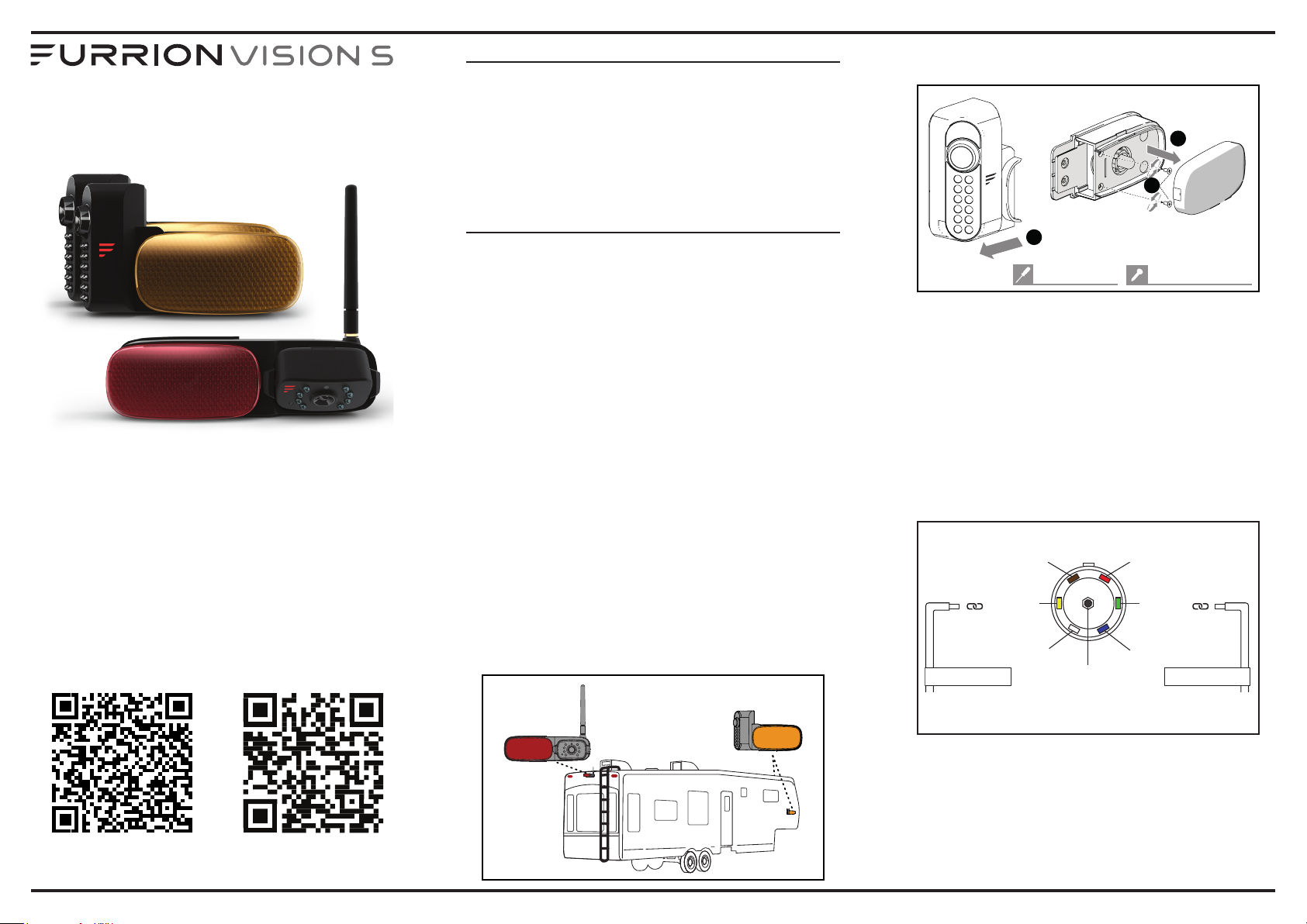
Rear camera
position
Side camera
position
2. Remove the lens cover and detach the camera from the
marker light bracket (right side camera shown).
1
2
3
#1 Phillips head
#4x1/4" self-tapping
3. Remove the original marker light from the corresponding
location.
4. Connect the bare ends of the power cable on the back of
the bracket to the nearest 12V / 24V power supply:
Red (V+_Camera): to the positive wire of the running light
circuit;
Black (GND): to ground;
Yellow (Trigger): to left/right turn signal [only available
for LED versions];
Brown (V+_Lamp): to positive wire of the running light
circuit;
Example of a typical 7-way connection
Tail lights/running lights
Trigger Signal
Note: This image is only for identifying the color code of the signal
wires and the user does not have to route the trigger wires to 7-way.
(Brown)
Left turn signal &
brake light
(Yellow)
Ground
(White)
Backup lights
Auxiliary 12v+/charging
(Red)
Right turn signal &
brake light
(Green)
Trailer brake control
(Blue)
Trigger Signal
Note: Ensure that the fuse on the connected power line
provides additional 1A fusing current for the camera.
Ensure proper cable isolation for all bare ends (e.g., by using
insulation tape).
How to Video Full Manual Download
Page 2
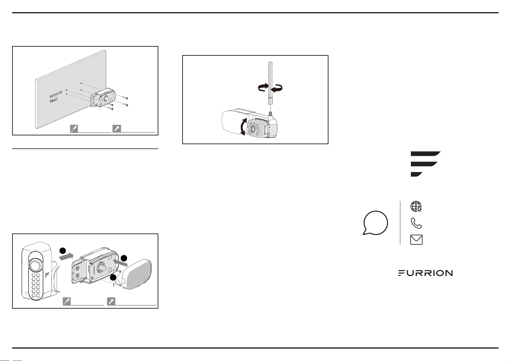
5. Secure the gasket and marker light bracket onto your
vehicle using four flat head #6 x 3/4” self-drilling screws.
If the mounting surface is uneven, apply sealant around
the gasket for better sealing.
• For the rear camera, mount the antenna onto the
camera securely and keep the antenna straight, adjust
the view angle of the camera by rotating it upwards and
downwards (0~50°) so that you can see the bottom edge
of your vehicle and the road conditions behind.
Torque: ≤8 In-lbs
#2 Phillips head
#6x3/4" flat head
Mount Cameras (right side shown)
• Reattach the camera to the marker light bracket.
Before fixing the camera, check its pairing status
with the monitor by resuming power temporarily.
Forincandescent lights, make sure the removable light
bulb is properly installed before replacing the lens cover.
Ensure that the lens on the camera face backwards after
installation, with the MONITOR PAIRING button at the
bottom.
If you cannot find the video from the camera on the
monitor screen or you have an unbundled camera, see
the Quick Start Guide for the monitor or online user
manual for pairing procedures.
1
3
2
#1 Phillips head
#4x1/4" self-tapping
Tip: See the complete user manual online for detailed
functional explanations.
www.furrion.com/support
1-800-789-3341
?
@
support@furrion.com
Furrion Innovation Center & Institute of Technology
• 52567 Independence Ct., Elkhart, IN 46514, USA
©2007-2020 Furrion Ltd. Furrion® and the Furrion logo are
trademarks licensed for use by Furrion Ltd. and registered
inthe U.S. and other countries.
Patents pending (FCE48TASL)
IG-FCM00009 V2.0
 Loading...