

Page 1
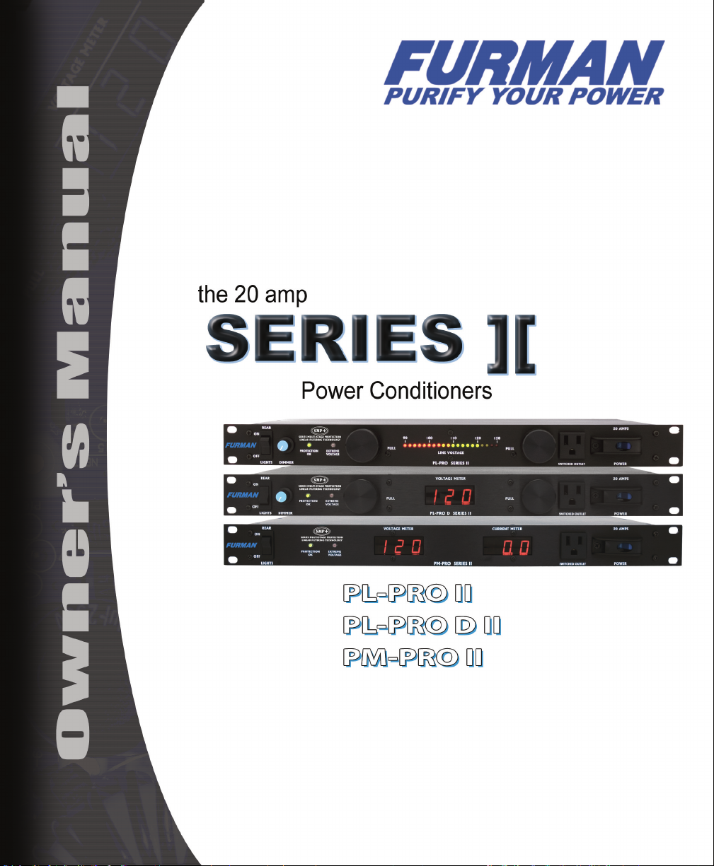
SERIES II 20 AMP POWER CONDITIONERS
Page 2

SERIES II 20 AMP POWER CONDITIONERS
1
Furman Series II Features
• SMP+ with extreme voltage shutdown
• LiFT (Linear Filtering Technology) with zero ground contamination
• Eight rear panel outlets and one front panel outlet
• BNC connector on the rear panel allows you to attach any standard
(12VAC 0.5 amp) gooseneck lamp to illuminate the rear of your rack
• 20 amp rating, with circuit breaker
• Three year limited warranty
PL-PRO Series II Additional Features
• Two retractable, long-life, low-heat LED light xtures with dimmer
control for rack illumination
• Front panel meter to display incoming line voltage ranging from 90 to
128 volts
PL-PRO D Series II Additional Features
• Two retractable, long-life, low-heat LED light xtures with dimmer
control for rack illumination
• Laboratory precision Digital Voltmeter displays incoming line voltage
(+/- 1.5 VAC)
PM-PRO Series II Additional Features
• Laboratory precision Digital Voltmeter displays incoming line voltage
(+/- 1.5 VAC)
• True RMS Current Meter displays power draw (+/- 0.5 amp)
Page 3

SERIES II 20 AMP POWER CONDITIONERS
2
I N T R O D U C T I O N
Thank you for purchasing a Furman Series II
Power Conditioner, and Congratulations on
your choice. The Series II power conditioners
feature Furman’s revolutionary Series MultiStage Protection Plus (SMP+) circuit, as well
as our exclusive Linear Filtering Technology
(LiFT). Together, these technologies comprise
what is, without question, the world’s most
advanced and comprehensive transient
voltage surge suppressor / conditioner.
SMP+ (Series Multi-Stage Protection
Plus)
Furman’s SMP+ surge suppression virtually
eliminates service calls. Traditional surge
suppression circuits “sacrice” themselves
when exposed to multiple transient voltage
spikes, requiring the dismantling of your
system, and repair of your surge suppressor.
Not so with SMP+. With Furman’s SMP+,
damaging transient voltages are safely
absorbed, clamped, and dissipated.
Unique to Furman’s SMP+ is its unparalleled
clamping voltage. While other designs offer
clamping voltages that are well above 330
Vpk, Furman’s SMP+ clamps at 188 Vpk,
(133 VAC RMS). This unprecedented level
of protection is only available with Furman’s
SMP+ technology. Additionally, Furman’s
trusted over-voltage circuitry protects against
all too frequent accidental connections to 208
or 240 VAC, by shutting off the incoming power
until the over voltage condition is corrected.
[For E versions: Furman’s SMP+ clamps at 376
VpK, (266 VAC RMS.)]
LiFT (Linear Filtering Technology)
Unfortunately, traditional AC lter - conditioners
have been designed for unrealistic laboratory
conditions. Prior technologies, whether
multiple pole lter or conventional series
mode, could actually harm audio and video
performance more than they help, due to the
resonant peaking of their antiquated, non-linear
designs. Under certain conditions, these
designs can actually add more than 10 dB of
noise to the incoming AC line! Worse still, lost
digital data, the need to re-boot digital pre-sets,
or destroyed digital converters are frequently
caused by excessive voltage spikes and AC
noise contaminating the equipment ground.
Furman’s SMP+ with LiFT takes another
approach, ensuring optimal performance
through linear ltering and no leakage to
ground.
S A F E T Y I N F O R M AT I O N
To obtain best results from your Furman Series
II Power Conditioner, please read this manual
Page 4

SERIES II 20 AMP POWER CONDITIONERS
3
carefully before using.
WA R N I N G
To reduce the risk of electrical shock, do not
expose this equipment to rain or moisture.
Dangerous high voltages are present inside the
enclosure. Do not remove the covers. Refer
servicing to qualied personnel only. The
lightning ash with an arrowhead symbol, is
intended to alert the user to the presence of
un-insulated dangerous voltage within the
product’s enclosure that may be of sufcient
magnitude to constitute a risk of electric shock.
I M P O R TA N T S A F E T Y
I N S T R U C T I O N S
(Please read prior to installation)
1. Please read and observe all safety and
operating instructions before installing your
Series II unit. Retain these instructions for
future reference.
2. Your Series II unit should not be used near
water – for example, near a bathtub, washbowl,
kitchen sink, laundry tub, in a wet basement,
near a swimming pool, etc.
3. Do not place your Series II unit near heat
sources such as radiators, heat registers,
stoves, or other appliances that produce heat.
4. The PL-PRO II, PL-PRO D II, and PM-PRO
II should only be connected to a 120 VAC,
60Hz, 20 amp grounded electrical outlet. Do
not defeat the ground or change polarization of
the power plug. (E versions 220 – 240 VAC 50 Hz., J
versions 100 – 120 VAC 50 Hz.)
5. Route the power cord and other cables so
that they are not likely to be walked on, tripped
over, or stressed. Pay particular attention
to the condition of the cords and cables at
the plugs, and the point where they exit your
Series II unit. To prevent risk of re or injury,
damaged cords and cables should be replaced
immediately.
6. Clean your Series II unit with a damp cloth
only. Do not use solvents or abrasive cleaners.
Never pour liquid on or into the unit.
7. Your Series II unit should be serviced by
qualied service personnel when:
• The power supply cord or the plug has been
frayed, kinked, or cut.
• Objects have fallen or liquid has spilled into
the unit.
• The unit has been exposed to rain or other
moisture.
• The unit does not appear to operate normally.
• The “Protection OK” indicator is not lit.
• The unit has been dropped, or the enclosure
has been damaged.
• The retractable LED lights have failed. (not
applicable to the PM-PRO II)
8. Your Series II unit requires that a safety
ground be present for proper operation. Any
attempt to operate the unit without a safety
ground is considered improper operation and
could invalidate the warranty.
Page 5

SERIES II 20 AMP POWER CONDITIONERS
4
9. Do not attempt to service your Series II unit
beyond what is described in this manual. All
other servicing should be referred to qualied
service personnel.
ADDITIONAL F E A T U R E S
PL-PRO SERIES II
The PL-PRO II features LED rack lights which
produce virtually no heat and provide an
extremely long life span. A dimmer control
for the rack lights allows the user to adjust the
level of illumination or simply switch the lights
off. A rear mounted BNC jack accepts any
standard (12VAC 0.5 amp) gooseneck lamp for
rear rack illumination.
Additionally, the PL-PRO II offers a 20 segment
LED bar-graph meter that displays incoming
voltage between 90 and 128 volts in 2-volt
steps. The normal range voltages are indicated
in green, with moderately and extremely high
or low voltages in yellow and red respectively.
The voltmeter’s accuracy is ±2 volts. It can
easily be re-calibrated, if necessary.
versions 180 – 256 VAC in 4 volt steps)
The PL-PRO II has a master magnetic circuit
breaker switch for the front and rear outlets that
is protected from accidental disconnection by
a hinged cover. The PL-PRO II also features a
10 foot, 12 gauge heavy-duty power cable.
PL-PRO D SERIES II
(E-
The PL-PRO D II features LED rack lights
which produce virtually no heat and provide
an extremely long life span. A dimmer control
for the rack lights allows the user to adjust
the level of illumination. A rear mounted BNC
jack accepts any standard (12VAC 0.5 amp)
gooseneck lamp for rear rack illumination.
Additionally, the PL-PRO D II offers a
laboratory precision digital meter that displays
incoming voltage in 1-volt steps. The
voltmeter’s accuracy is ±1.5 volt.
The PL-PRO D II has a master magnetic circuit
breaker switch for the front and rear outlets
that is protected from accidental disconnection
by a hinged cover. The PL-PRO D II also
features a 10 foot, 12 gauge heavy-duty power
cable.
PM-PRO SERIES II
The PM-PRO II features two laboratory
precision digital meters that display both
incoming voltage in 1-volt steps, and a true
R.M.S. current meter that measures the AC
power draw within 0.5 amp. A rear mounted
BNC jack accepts any standard (12VAC 0.5
amp) gooseneck lamp for rear rack illumination.
The PM-PRO II has a master magnetic circuit
breaker switch for the front and rear outlets
that is protected from accidental disconnection
by a hinged cover. The PM-PRO II also
features a 10 foot, 12 gauge heavy-duty power
cable.
Page 6

SERIES II 20 AMP POWER CONDITIONERS
5
O P E R AT I O N
Retractable Rack Lights, Rear Panel Lamp
and Dimmer Control:
The PL-PRO II and PL-PRO D II utilize a
dimmer control for the two retractable front
panel light tubes. The dimmer knob controls
the brightness of both light xtures. Turn
it clockwise to increase brightness; turn it
counterclockwise to decrease brightness.
When the lights are not in use, we recommend
turning the dimmer fully counterclockwise to
maximize the life of the LED’s, however, this
is not absolutely necessary. Whether the light
tubes are retracted or ush with the front panel,
there will be no appreciable heat regardless of
dimmer setting due to the efciency of our full
light spectrum LED’s.
All Series II units feature a rear rack BNC
socket which will accept any 12 VAC (0.5A)
gooseneck lamp assembly, (such as the
Multi -Segm ent L ED Voltme ter R eadi n gs
Mains Vltg. Voltage Status Voltmeter Reading Outlets
Furman GN-LED or GN-I). Simply slide the
BNC plug over the socket and rotate clockwise
until the connector snaps into the locked
position. The rear rack lamp can be powered
on or off with the rear light power switch
located on the far left of the front panel.
The Series II’s front panel LED lamps must
be replaced by qualied Furman service
personnel.
Multi-Segment LED voltmeter:
(PL-PRO II only)
This three-color, 20-LED bargraph is an
accurate, self checking AC voltmeter that
continually measures normal voltages. The
meter reads from 90 to 128 volts in 2 volt
increments (PL-PRO E II: 180 to 256 volts, in
4 volt increments). The normal range voltages
are indicated in green, with moderate and
extremely high or low voltages in yellow and
red respectively. The voltmeter provides three
special ashing patterns to indicate abnormal
conditions.
80-90 Low Marginal The LED beneath the 90V mark flashes ON
90-104 Low Meter Reads in Low Red ON
106-108 Medium Low Meter Reads in Low Yellow ON
110-120 Normal Meter Reads in Green ON
122-124 Medium High Meter Reads in High Yellow ON
126-128 High Meter Reads in High Red ON
130-140 High Marginal All Meter LEDs Flash ON
Above 140 Extreme (Shutdown) Meter off—Extreme Voltage LED illuminates OFF
Page 7

SERIES II 20 AMP POWER CONDITIONERS
6
current meter continually measures the total
(1) If only the single leftmost (beneath the
90V mark – 180V for E version) LED
ashes, the input voltage is marginally
low.
(2) If all of the LED’s on the voltmeter
ash, the input voltage is marginally
high. Power to the PL-PRO’s outlets
will remain unless the incoming
voltage rises above the Extreme
Voltage Shutdown cutoff voltage
(135 - 140 volts / 260 – 265 volts E
version / 120 – 125 volts J version).
(3) If none of the LED’s on the voltmeter
are lit, and the Extreme Voltages LED
indicator is illuminated, then the PL Plus II has shut down power to its
outlets because the input voltage is in
a range considered extreme (in excess
of 135 volts - 260 volts E version /
120 volts J version).
Digital Voltmeter:
(PL-PRO D II and PM-PRO II only)
Furman’s laboratory precision AC digital
voltmeter continually measures incoming
voltages, within a typical tolerance of +/-
1.5VAC. It should be noted that the voltage
reading is incoming. No adjustment should be
necessary on these units.
Digital Current Meter: (PM-PRO II only)
Furman’s laboratory precision AC digital
circuit AC load, within a typical tolerance of +/-
0.5 amp. Because these meters feature true
R.M.S. technology, the current readings are
accurate regardless of load conditions (capacitive,
inductive or resistive).
NOTE: The PL-PRO II, PL-PRO D II, and PMPRO D II, do not compensate for high or low
line voltage. If you frequently move your rack to
different locations, derive power from generators,
use long extension cords, travel internationally,
or are in an area prone to brownouts, you may
benet from the use of one of Furman’s AC Line
Voltage Regulators.
On/Off Circuit Breaker:
This 20 amp capacity magnetic circuit breaker
switch is specically designed to stand up to
the enormous high inrush current demands of
many Power Ampliers. Additionally, the switch
is shielded from accidental power disconnection
with a hinged cover. (E-versions feature 16 amp
capacity)
Extreme Voltage Shutdown Indicator:
This LED is normally off. It monitors a hazard
common in the entertainment industry: wiring
faults – for example, accidental connection
to 220VAC where 120VAC is expected, or an
open neutral from a 208 or 240VAC feed. The
Series II SMP+ circuit senses voltages that
are so high that operation would be impossible
and shuts the power down before damage can
occur. Upon initially applying power to these
Page 8

SERIES II 20 AMP POWER CONDITIONERS
7
units, the Extreme Voltage indicator LED will
light if the input voltage is above the extreme
voltage cutoff, and power will not be applied
to the unit’s outlets. If the unit has been
operating with an acceptable input voltage and
subsequently that voltage exceeds 135V, it will
shut off power to the outlet and the Extreme
Voltage LED will light. (E version: over voltage
shut down is 260 VAC. Guards against open
neutral and accidental connection to 300+
VAC)
Protection OK Indicator:
Although the Furman SMP circuit assures
virtually protection from transient voltage
spikes and surges, nature has a way of
occasionally creating electrical forces that are
beyond the capabilities of any TVSS device to
absorb without some degree of damage. In
the rare instance that this occurs, the green
“Protection OK” LED indicator located on your
front panel will dim. If this happens some level
of protection from voltage surges will remain,
but the Furman’s clamping voltage rating will
be compromised. The unit must be returned
to Furman Sound, or an authorized Furman
Service center for repair.
NOTE: If the mains power is above the high
cutoff voltage and has caused the unit to
remove power from its outlets, it cannot restore
power without the operator manually turning
the unit off, then on again. Avoid turning the
unit back on, without rst checking the source
of the problem, and perhaps changing the AC
source.
T R O U B L E S H O O T I N G G U I D E
1.) Symptom: No power to the AC outlets.
Possible Cause: Circuit breaker switch has
tripped to the off position, due to excessive
load.
Action Needed: Remove one piece of
equipment from the Series II unit, open the
hinged switch / breaker cover, and reset the
switch to the on position.
2.) Symptom: No power to the AC outlets,
“Protection OK” indicator is not lit.
Possible Cause: Either the AC outlet to which
your Series II device is connected has no AC
voltage present, or the unit has been subjected
to a sustained voltage in excess of 400 Volts.
Action Needed: Plug the Series II unit into an
AC receptacle where AC voltage is present. If
the problem persists, the protection circuit may
be damaged, and require factory service.
3.) Symptom: Extreme Voltage indicator lit.
Possible Cause: Input voltage is above 135-
140 volts (270 – 280 volts E version), causing
power to the unit’s outlets to be shut down.
Additionally, if the voltage is below 85 - 90 volts
at turn on, the unit will not allow AC voltage to
reach the outlets.
Action Needed: Correct the line voltage, then;
turn the unit on. Consider installing a Furman
voltage regulator.
Page 9

SERIES II 20 AMP POWER CONDITIONERS
8
DEFINITIONS
SPIKE: This is a pulse of energy on the
power line. Spikes can have voltages as
high as 6000 volts. Though they are usually
of very short duration, the energy they
contain can be considerable, enough to
damage sensitive solid-state components
in audio and computer equipment. Spikes
can also foul switch contacts and degrade
wiring insulation. They are an unavoidable
component of electric power. They are caused
unpredictably by electric motors switching
on or off (on the premises or outside), utility
company maintenance operations, lightning
strikes and other factors. Spikes (also called
surges or transients) are absorbed by special
components in the series II Series Multi-Stage
Protection circuitry to provide safe voltage
levels to protect your equipment.
RFI/EMI INTERFERENCE: Noise from RFI
(Radio Frequency Interference) or EMI (Electro
Magnetic Interference) involves lower voltages
and less energy than is found in spikes, but it
is continuous rather than transient in nature.
It is not likely to cause damage, but it can
certainly be annoying, producing static in audio
circuits, “snow” on video screens, or garbled
data in computers. Noise can be introduced
into AC lines by nearby radio transmitters,
certain kinds of lighting, electric motors, and
other sources. Because noise occurs at higher
frequencies than the 50 or 60 Hz AC line, it can
be effectively reduced through use of low-pass
ltering.
THREE YEAR LIMITED
WARRANTY
Furman Sound, LLC., having its principal place
of business at 1997 South McDowell Blvd.,
Petaluma, CA 94954 (“Manufacturer”) warrants
its 20 amp Series II Power Conditioners (the
“Product”) as follows:
Manufacturer warrants to the original
Purchaser of the Product that the Product sold
hereunder will be free from defects in material
and workmanship for a period of three years
from the date of purchase. The Purchaser
of the product is allowed fteen days from
the date of purchase to complete warranty
registration by mail or on-line at the Furman
website. If the Product does not conform to this
Limited Warranty during the warranty period
(as herein above specied), Purchaser shall
notify Manufacturer in writing of the claimed
defects. If the defects are of such type and
nature as to be covered by this warranty,
Manufacturer shall authorize Purchaser to
return the Product to the Furman factory or to
an authorized Furman repair location. Warranty
claims should be accompanied by a copy of
the original purchase invoice showing the
purchase date; this is not necessary if the
Warranty Registration was completed either via
the mailed in warranty card or on-line website
Page 10

SERIES II 20 AMP POWER CONDITIONERS
9
registration. Shipping charges to the Furman
factory or to an authorized repair location must
be prepaid by the Purchaser of the product.
Manufacturer shall, at its own expense, furnish
a replacement Product or, at Manufacturer’s
option, repair the defective Product. Return
shipping charges back to Purchaser will be
paid by Manufacturer.
THE FOREGOING IS IN LIEU OF ALL
OTHER WARRANTIES, EXPRESS OR
IMPLIED, INCLUDING BUT NOT LIMITED
TO THE IMPLIED WARRANTIES OF
MERCHANTABILITY AND FITNESS FOR
A PARTICULAR PURPOSE. Manufacturer
does not warrant against damages or defects
arising out of improper or abnormal use of
handling of the Product; against defects or
damages arising from improper installation,
against defects in products or components
not manufactured by Manufacturer, or against
damages resulting from such non-Manufacturer
made products or components. This warranty
shall be cancelable by Manufacturer at its
sole discretion if the product is modied in
any way without written authorization from
Furman Sound. This warranty also does not
apply to Products upon which repairs have
been affected or attempted by persons other
than pursuant to written authorization by
Manufacturer.
THIS WARRANTY IS EXCLUSIVE. The sole
and exclusive obligation of Manufacturer shall
be to repair or replace the defective Product
in the manner and for the period provided
above. Manufacturer shall not have any other
obligation with respect to the Products or
any part thereof, whether based on contract,
tort, strict liability or otherwise. Under no
circumstances, whether based on this Limited
Warranty or otherwise, shall Manufacturer be
liable for incidental, special, or consequential
damages. Manufacturer’s employees or
representatives’ ORAL OR OTHER WRITTEN
STATEMENTS DO NOT CONSTITUTE
WARRANTIES, shall not be relied upon by
Purchaser, and are not a part of the contract
for sale or this limited warranty. This Limited
Warranty states the entire obligation of
Manufacturer with respect to the Product. If
any part of this Limited Warranty is determined
to be void or illegal, the remainder shall remain
in full force and effect.
S E R V I C E
Before returning any equipment for repair,
please be sure that it is adequately packed and
cushioned against damage in shipment, and
that it is insured. We suggest that you save
the original packaging and use it to ship the
product for servicing. Also, please enclose
a note giving your name, address, phone
number and a description of the problem.
NOTE: All equipment being returned for
repair must have a Return Authorization (RA)
Number. To get an RA Number, please call the
Furman Service Department: (707) 763-1010,
ext. 121. Please display your RA Number
prominently on the front of all packages.
Page 11

SERIES II 20 AMP POWER CONDITIONERS
10
SPECIFICATIONS
Current rating:
20 amps (“E” versions 16 amps)
Operating Voltage:
90 to 140 VAC (“E” versions 180 to 280 VAC)
Over Voltage Shutdown:
140 VAC typically (“E” versions 260 VAC typically, “J” versions 125 VAC typically)
Voltmeter Accuracy:
PL-PRO II only: ±2 VAC, calibrated with internal
trimpot adjustments
PL-PRO D II & PM-PRO II: ±1.5 VAC,
PM-PRO II Current meter: ±0.5 amp
Spike Protection Modes:
Line to neutral, zero ground leakage
Spike Clamping Voltage:
188 Vpk @ 3,000 amps, (133 VAC RMS)
(“E” Version: 376 Vpk (266 VAC RMS)
Response time:
1 nanosecond
Maximum surge current:
6,500 amps
Noise attenuation:
10 dB @ 10 kHz
40 dB @ 100 kHz
100 dB @ 10 MHz
Linear attenuation curve from 0.05 - 100 ohms line impedance
Mechanical:
Dimensions: 1.75” H x 19” W x 10.5” D.
Weight: 11 lbs (5 kg).
Construction: Steel chassis, .125” brushed and black anodized aluminum front panel; glass epoxy printed circuit boards
Power Consumption:
PL-PRO II, 12 watts
PL-PRO D II, 12 watts
PM-PRO II, 12 watts
Safety Agency Listings:
CE, NRTL-C
Make sure to pick up one of
Furman’s goosneck lights the perfect accesory for your
Series II unit.
GN-LED
GN-I
Page 12

SERIES II 20 AMP POWER CONDITIONERS
111804-C
Furman Sound, LLC.
1997 South McDowell Blvd.
Petaluma, California 94954-6919 USA
Phone: 707-763-1010 Fax: 707-763-1310
Web: www.furmansound.com
E-mail: info@furmansound.com
 Loading...