

Page 1
H A - 6 A B / H A - 6 A B E M a n u a l
Page 2

H A - 6 A B / H A - 6 A B E M a n u a l
INTRODUCTION
Congratulations on your purchase of a Furman Sound HA-6AB. You have chosen the
most versatile headphone amplifi er available.
The HA-6AB is a unique combination of a
headphone amplifi er and a conventional power
amplifi er, which can save the expense of an
extra power amplifi er in many situations. Its
high power capacity provides adequate headphone listening levels without distortion in any
environment. Additionally, the HA-6AB’s toroidal
transformer assures noise-free performance. It
eliminates electrical hum and mechanical noise
from the unit itself, as well as leakage into other
sensitive equipment, such as mic preamplifi ers,
video monitors, etc. The HA-6AB is designed
for recording studios, rehearsal studios, language labs, and for use in demonstrations of
audio tracks or audio equipment.
FEATURES
Powers headphones and speakers
20 watts per channel, stereo
Toroidal power transformer for ultra-
quiet performance
6 headphone outputs, each with its
own volume control
Separate front panel switches for
speakers and remote headphone
outputs or a second set of speakers
Automatically switches to mono
mode when right channel is not
used
Signal-present and Overload LED’s
for each channel
Ground lift switch
Power-on indicator
Convenient Remote/Satellites outlet
provides signal for up to 12 remote
headphone stations. (Such as the
Furman HR-2 remote station.)
DESCRIPTION
The HA-6AB is a single rack space 20 watt per
channel stereo amplifi er. Unlike a conventional
power amplifi er, however, it has six headphone
outputs (stereo phone jacks) on the front panel,
each with its own volume control. When used for
overdubbing or rehearsal, this provides more than
adequate volume in all headphones (even lowimpedance models), and allows each musician to
set his or her own listening level. When overdubbing is complete and the musicians remove their
headphones, the HA-6AB can power the tape
playback through a set of studio monitor speak-
Important Note: To obtain best results from this Furman Sound electronic product, please be sure
to read this manual carefully before using it. Please fi ll out and return the Warranty Registration
Card immediately to obtain full protection under the terms of the Limited Warranty, in case your
ownership documents are lost. Please verify that the serial number shown on the Warranty Card
matches the serial number on your unit.
Page 3

3
H A - 6 A B / H A - 6 A B E M a n u a l
ers, selected by pressing front panel pushbuttons.
Without the HA-6AB, a separate amplifi er would
be needed for the studio speakers. The HA-6AB
also features a convenient input level control on
the left side of the front panel. A pair of yellow
LED’s (one for each channel) light up whenever a
signal is present. Another pair of red LED’s shows
an overload condition in either channel.
The Furman HA-6AB’s 20 watts-per-channel
make it ideal as a low distortion headphone driver
for the most critical listening situations. While
most headphone amplifi ers provide half a watt or
less per headphone channel, the HA-6AB’s higher
power can drive headphones of any impedance
to their full rated listening level, and do so with
minimal noise and distortion. Its power capacity
is also just right for the small near fi eld monitors
used in most recording studios; as a comparison
with the main control room monitors, it can power
them without overpowering them. On the studio
fl oor, a set of small monitor speakers driven by
the HA-6AB can make a session progress more
effi ciently by giving the musicians a chance to
hear a playback without needing to disconnect
themselves from their equipment and walk into
the control room. Additionally, the HA-6AB is fully
protected against thermal overload, and it can
withstand a short circuit on any or all outputs for
an indefi nite time without damage.
ACCESSORIES
Model HR-2 Headphone Remote Station: A
compact, unobtrusive box that clamps to any
mic stand, providing two headphone jacks, each
with its own volume control. Up to twelve HR-2
boxes may be connected to a HA-6AB, employing
standard microphone cables (depending on the
impedance of the headphones used).
USES OF HA-6AB
The HA-6AB may be used as a power amplifi er to drive up to two pairs of speakers, or as a
headphone amplifi er for one to six pairs of headphones, or both. Additional headphones may be
connected through use of HR-2 Remote Boxes.
RECORDING
In the recording studio, headphones are most
often used in the overdubbing process, whereby
new musical tracks are recorded in synchronization with previously recorded tracks. The
musicians doing the overdub hear the previously
recorded tracks in their headphones, and play
along with them. Synchronization is maintained
because almost all multitrack recorders have the
capability of playing back through certain channels of the record head while recording through
others. In this way, it is possible to build up a
complete recording of many tracks, adding one
or more new tracks with each overdub.
Headphones are much preferred to speakers for
cueing the overdub, because of the presence of
open microphones which would pick up the cue
tracks as well as the overdub. Any trace of the cue
tracks in the overdub tracks would degrade the
tracks’ separation and make it diffi cult to achieve
a good mix later on. In fact, even if headphones
Page 4
H A - 6 A B / H A - 6 A B E M a n u a l
are used, it is important that they clamp tightly to
the musicians’ heads so that a minimal amount
of sound leaks out.
The cue mix heard in the headphones is a combination of the previously recorded tracks along
with the new sounds being added. It is generally
derived from a “Cue” or “Headphone” mixing buss
on the recording console, which is then routed to
the Left and Right Inputs on the HA-6AB’s rear
panel. If this mix is mono, connect it to the Left
Input. The HA-6AB will then automatically be in
mono mode, so that the mix can be heard with
both ears (and both speakers, if used).
In a small studio, if no more than six sets of headphones are needed, it may be most convenient to
locate the HA-6AB on the studio fl oor, and plug all
headphone sets directly into its front panel. You
may want to put a large, easily readable number
on each set so that each musician will be able to
locate his or her volume control, even if the cables
become tangled.
In a larger studio, you may fi nd it more practical to use several HR-2 Remote Stations at
strategic locations around the studio, while the
HA-6AB itself is installed in the control room. In
this arrangement, the Speaker buttons will be
more easily accessible to the engineer, and each
musician’s volume control will be right on the mic
stand in front of him or her. And of course, if the
engineer or others in the control room want to
hear the cue mix, they can just plug headphones
into any of the HA-6AB’s front panel jacks. See
the section on “Use of the HR-2 Remote Stations”
for additional details.
NOTE: For studios that require each tracking musician to have their own personalized mix, the Furman HDS-6/HR-6 or the HDS-16/HRM-16 may be
required as an alternative to the HA6-AB.
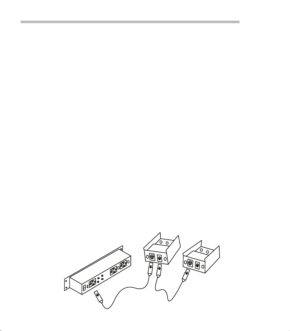
The HR-2 Remote Stations connect in “a daisy
chain” fashion to the Speaker B output on the
rear panel of the HA-6AB. This output is an XLR
connector, so that standard microphone cables
can be used. The HA-6AB connects to the fi rst
HR-2 box; another mic cable connects the fi rst
HR-2 box to the second HR-2 box; a third mic
cable connects the second HR-2 to the third
HR-2; and so forth. However, twelve HR-2 is the
recommended maximum.
Daisy-chaining HR-2 Remote Stations to the HA-6AB
Page 5

5
H A - 6 A B / H A - 6 A B E M a n u a l
USE OF THE HR-2 REMOTE
STATIONS (SATELLITES)
The HR-2 Remote Stations may be used to
increase the number of headphones which can
be accommodated by an HA-6AB, and to place
a volume control within reach of each individual
needing it. They are compact boxes which easily attach with a thumbscrew to any microphone
stand. Each HR-2 has two stereo volume controls
and two headphone jacks. There are also two
XLR connectors, one male and one female. These
may be used to “daisy chain” HR-2 boxes together
with standard microphone cables. Begin the chain
at the SPEAKER B - SATELLITE/REMOTE connector on the rear of the HA-6AB. The HA-6AB
connects to the fi rst HR-2 box; another mic cable
connects the fi rst HR-2 box to the second HR-2
box; a third mic cable connects the second HR-2
to the third HR-2; and so on. If low impedance
headphones are used, up to twelve HR-2’s may
be in the chain. If medium or high impedance
headphones are used, 25 or more Remote Stations may be chained. If desired, the clip on an
HR-2 box may be hung on a belt if no microphone
stand is convenient.
One or two sets of studio speakers may be connected to the HA-6AB. If two sets are needed,
the “B” pair must be connected to the XLR output
using a custom made cable. HR-2 Remote Stations cannot be used in this case.
REHEARSAL
Headphones are used in rehearsal sessions
not only to avoid disturbing neighbors with loud
sounds, but also to provide each musician an
easily controlled mix of all the other tracks. Using headphones guarantees that each will hear a
balanced mix regardless of where they are positioned relative to various instruments or speakers
(a luxury not always available in performance). As
in recording, a mixing board must be used, whose
output will drive the HA-6AB either in mono (use
Left Input only) or stereo (use both inputs).
The main consideration in locating the HA-6AB is
whether each musician will need easy access to
his or her own volume control. If the musicians are
spread around a large room, the use of a chain of
HR-2 Remote Stations may be more convenient
than having each pair of headphones plug directly
into the HA-6AB.
LANGUAGE LABS
Language labs occasionally need to drive as
many as 50 headphone sets. If more than twenty
fi ve sets are required, they must be high-impedance types. HR-2 Remote Stations provide a
convenient way to place a volume control at
each listening position (two listeners can share
each box).
Page 6

6
H A - 6 A B / H A - 6 A B E M a n u a l
FRONT PANEL
INPUT LEVEL: The Input Level control provides a
means of scaling the effect of the individual headphone volume controls. The Input Level should
be adjusted so that there is an adequate range
of volumes available at each listening position,
so that any listener can be accommodated, and
the average listener’s volume will be set at about
halfway. The Input Level control is stereo; it affects
both left and right channels simultaneously.
SIGNAL PRESENT LIGHTS: These yellow LED’s
turn on whenever a signal exceeding 125 millivolts RMS (40 dB below full power) is present
at the HA-6AB’s input jack. They will increase in
brightness as the signal strength increases. This
feature is very useful and can provide a clue to
where the fault may lie if the expected program
is not heard at the listening stations.
OVERLOAD LIGHTS: These LED’s glow red to
indicate an overload in the HA-6AB. If the LED
lights up, either the drive level to the unit should
be reduced, or the setting of the Input Level control should be reduced until the LED remains off.
The lights turn on when the signal level at either
output approaches .5 to 1 dB of clipping. Once
triggered, the lights will stay lit for a minimum of
50 milliseconds so they can be easily seen, even
if the actual duration of the overload is much
shorter.
HEADPHONE JACKS / VOLUME CONTROLS:
Any type of headphones, wired with a standard
1/4” stereo phone plug, may be used successfully. All six outputs receive the same stereo
signal. They differ only in the individual volume
settings.
SPEAKER-A BUTTON: Depressing this button turns on the speakers connected to the
SPEAKER-A banana jacks on the rear panel, and
simultaneously turns off the signal to all the front
panel headphone outputs.
SPEAKER-B BUTTON: Depressing this button
turns on whatever is plugged into the SPEAKERB SATELLITE/REMOTE XLR connector on the
rear panel. This will be either a pair of speakers
or a chain of HR-2 Remote Stations. Therefore,
leave this button depressed when using Remote
Stations. Depressing it does not turn off the front
panel headphone outputs. See the section on the
Rear Panel for speaker wiring.
POWER LIGHT: Glows red when unit is receiving power and the ON-OFF SWITCH is in the
ON position.
Page 7

7
H A - 6 A B / H A - 6 A B E M a n u a l
sis ground). The connection from pin 1 to the shell
is optional on all 3 pin connectors, and can be
removed if present, by opening up the connector
on the cable and disconnecting it.
SPEAKER A OUTPUTS: These outputs should
be used when a pair of speakers is used as an
alternative to headphones, since the headphones
are switched off when the speakers are switched
on. The connections are 5-way binding posts,
which can accommodate dual banana plugs, bare
wires, or wires terminated in spade lugs.
SPEAKER B SATELLITE/REMOTE OUTPUT:
This output is a single male XLR connector containing both the left and right channel outputs. It
is wired as follows: Pin 3-left (high); Pin 2-right
(high); and Pin 1-low, common to both channels.
This output should be used as the starting point
for a chain of HR-2 Remote Stations (satellites).
It will receive signal whenever the front panel
SPEAKER B button is depressed. If necessary,
it may also be used to connect a second set of
speakers. However, if it is used for speakers, note
that depressing the SPEAKER B button will not
switch off the front panel headphone jacks in the
way that the SPEAKER A button does.
INPUTS: Quarter-inch (mono) phone jacks are intended for line level signals such as the outputs of
a mixer. Microphones and/or instrument pickups
may not have strong enough outputs to drive the
REAR PANEL
ON-OFF SWITCH: This switch turns the HA-6AB
on and off. For convenience, it is recommended
that the HA-6AB and any other rack-mount
equipment be powered through a switchable
outlet box, such as the Furman Sound PL-8 or
PL-PLUS Power Conditioner and Light Module.
The PL Series provides an easy way to power up
the whole rack with one front-panel switch, and
provides discreet illumination on dark stages and
studios as well. If you do use a switchable outlet
box, leave the HA-6AB’s on-off switch in the ON
position at all times.
GROUND LIFT SWITCH: In many installations,
hum-causing ground loops are formed by the
common connection of various pieces of equipment to the power line ground, and by contact
between chassis, as in a rack with metal rails.
Sliding the Ground Lift switch up completely
isolates all signal grounds from the chassis,
breaking any ground loops. The chassis always
remains connected to the ground pin on the AC
cord for safety and to provide shielding against RF
interference. Try both positions of the Ground Lift
switch, and leave the switch in the position that
results in the least hum in your system.
Note: The ground lift can be rendered ineffective
by 3 pin audio connectors that tie pin 1 (signal
ground) to the metal shell of the connector (chas-
120 VAC
50/60 H
z
130 Watts
LIFT
GR OU ND
OFF
ON
SATELLITE / REMOTE
BALANCED IN PUT
LEFT INPUT
HE ADP HON E/
MO NI TO R
AMPLIFIER
BALANCED IN PUT
RIGHT INPUT
SPEAKER B
SPEAKER A
RIGHTLEFT
AVIS:
RISQUE DE CHOC
ELECTRIQUE -- NE PAS OUVRIR
RISK OF ELECTRIC SHOCK. DO NOT OPEN.
REFER SERVICING TO QUALIFIED SERVICE
PERSONNEL. TO REDUCE THE RISK OF FIRE
OR ELECTRIC SHOCK DO NOT EXPOSE THIS
EQUIPMENT TO RAIN AND MOISTURE.
CAUTION!
LISTED
7Z37
PROFESS IONAL
AUDIO EQUIPME NT
® ®
Page 8

HA-6AB directly without fi rst being preamplifi ed.
The 1/4” phone inputs are stereo jacks (tip-ringsleeve) wired for a balanced input. If a mono
phone plug is inserted, the input will automatically
be converted to unbalanced. If using a mono signal plug into the left ¼” jack the HA-6AB will send
signal to both left and right channels.
The HA-6AB is also equipped with left and right
balanced female XLR connectors in addition to
the standard 1/4” phone jacks. Balanced lines
offer the benefi ts of cancellation of hum, noise,
and RF interference which may be picked up in
the interconnecting cables. For balanced connections, shielded twisted pair cable must be
used. The wiring is as follows: Pin 1-shield; Pin
2-signal positive; and Pin 3-signal negative. The
XLR inputs can not be used in mono like the ¼”
input jacks.
CAUTION! This section is intended to assist the
professional user with considerable experience
in electronics to achieve a better understanding of the operation of the HA-6AB. Under no
circumstances should persons without electronics troubleshooting experience and training undertake repairs on their own. There are no user
serviceable parts inside the HA-6AB. All problems
should be referred to the factory or to other qualifi ed service personnel.
The inputs to the HA-6AB proceeds from the
input connectors to op-amplifi er buffers wired as
differential (balanced) amplifi ers.
The input connectors are stereo 1/ 4” phone jacks.
In the HA-6AB, these will be paralleled by XLR
connectors. If a mono plug is inserted, the ring
connection will be grounded through the body of
the plug, converting the differential amplifi er to a
noninverting amplifi er. After the buffers, the left
and right signals proceed to the two decks of the
stereo Input Level control.
The HA-6AB’s power amplifi cation is derived from
a pair of LM1875 integrated circuits, which have
internal short-circuit and thermal overload protection. They are set for a voltage gain of 26 dB.
The LM1875’s drive the speaker outputs directly.
The headphone outputs fi rst pass through special
high-power pots wired as volume controls.
The HA-6AB’s power supply provides +/-24 volts
unregulated to the LM1875 stages, which may
drop to +/-20 volts under full load. A network of
dropping resistors and zener diodes provides ±15
volts to the rest of the circuit.
Both the Overload LED’s and the Signal Present
LED’s monitor signal levels at the output (before
the volume controls).
INSTALLATION
The HA-6AB is intended for mounting in
standard 19” equipment racks. Standard racks
come equipped with mounting rails with holes
tapped for 10-32 machine screws. Be sure to
use only 10-32 screws (in particular, avoid 1024 screws, which will fi t if forced but will strip
the threads). To avoid marring the panel when
tightening the screws, use nylon washers under
the screw heads.
Page 9

For best results, the input cables plugged into
the HA-6AB should be shielded. Balanced
connections should use shielded, twisted-pair
cable. Headphone cables and speaker cables
do not need to be shielded, though no harm is
done if shielded cables (such as microphone
cables) are used.
THREE YEAR LIMITED
WARRANTY
Furman Sound, Inc., having its principal place
of business at 1997 South McDowell Blvd.,
Petaluma, CA 94954 (“Manufacturer”) warrants
its HA-6AB (the “Product”) as follows:
Manufacturer warrants to the original
Purchaser of the Product that the Product sold
hereunder will be free from defects in material and
workmanship for a period of three years from the
date of purchase. The Purchaser of the product
is allowed fi fteen days from the date of purchase
to complete warranty registration by mail or online at the Furman website. If the Product does
not conform to this Limited Warranty during the
warranty period (as herein above specified),
Purchaser shall notify Manufacturer in writing of
the claimed defects. If the defects are of such
type and nature as to be covered by this warranty, Manufacturer shall authorize Purchaser
to return the Product to the Furman factory or to
an authorized Furman repair location. Warranty
claims should be accompanied by a copy of the
original purchase invoice showing the purchase
date; this is not necessary if the Warranty Registration was completed either via the mailed in
warranty card or on-line website registration.
Shipping charges to the Furman factory or to an
authorized repair location must be prepaid by the
Purchaser of the product. Manufacturer shall, at
its own expense, furnish a replacement Product
or, at Manufacturer’s option, repair the defective
Product. Return shipping charges back to Purchaser will be paid by Manufacturer.
THE FOREGOING IS IN LIEU OF ALL
OTHER WARRANTIES, EXPRESS OR IMPLIED,
INCLUDING BUT NOT LIMITED TO THE IMPLIED WARRANTIES OF MERCHANTABILITY
AND FITNESS FOR A PARTICULAR PURPOSE.
Manufacturer does not warrant against damages
or defects arising out of improper or abnormal
use of handling of the Product; against defects
or damages arising from improper installation,
against defects in products or components not
manufactured by Manufacturer, or against damages resulting from such non-Manufacturer made
products or components. This warranty shall be
cancelable by Manufacturer at its sole discretion if the product is modifi ed in any way without
written authorization from Furman Sound. This
warranty also does not apply to Products upon
which repairs have been affected or attempted by
persons other than pursuant to written authorization by Manufacturer.
THIS WARRANTY IS EXCLUSIVE. The
sole and exclusive obligation of Manufacturer
shall be to repair or replace the defective Product in the manner and for the period provided
above. Manufacturer shall not have any other
Page 10

obligation with respect to the Products or any
part thereof, whether based on contract, tort,
strict liability or otherwise. Under no circumstances, whether based on this Limited Warranty
or otherwise, shall Manufacturer be liable for
incidental, special, or consequential damages.
Manufacturer’s employees or representatives’
ORAL OR OTHER WRITTEN STATEMENTS DO
NOT CONSTITUTE WARRANTIES, shall not be
relied upon by Purchaser, and are not a part of
the contract for sale or this limited warranty. This
Limited Warranty states the entire obligation of
Manufacturer with respect to the Product. If any
part of this Limited Warranty is determined to be
void or illegal, the remainder shall remain in full
force and effect.
SERVICE
Page 11

OUTPUTS:
Power: 20 watts per channel, stereo, into either 4 ohms
or 8 ohms, 20 Hz to 20 KHz.
Connectors: Speakers A: 5-way binding posts (accommodates
dual banana plugs, spade lugs, bare wires, etc.)
Speakers B-Satellite
Remote: Male XLR.
INPUTS:
Input Impedance: 20K ohms.
Sensitivity: -4 dBV (635 mv) required for full output.
Connectors: HA-6AB, both stereo phone (balanced) and XLR
(balanced).
GENERAL:
Distortion: .01 % THD at full rated power at 1 KHz; .05% THD
20Hz to 20 KHz.
Signal to Noise: Greater than 99 dB below full rated output.
Frequency Response: +0, -1 dB from 20 Hz to 20 KHz, 1 watt output.
Dynamic Headroom: 2 dB, stereo, measured with 10 ms toneburst at I KHz,
1 % duty cycle.
Power Requirement: HA-6AB: 120 VAC, 60 Hz, 70 watts
HA-6ABE: 230 VAC, 50/60 Hz, 70 watts
MECHANICAL:
Dimensions: 1.75" H x 19" W x 7.25" D. Wt: 7.5 lbs (3.4 kg)
Page 12

Web: www.furmansound.com
 Loading...