

Page 1
FURMAN
SOUND,
INC.
30
RICH STREET
GREENBRAE, CALIFORNIA 94904
PHONE:
(41s)
927-1225
FAX:
(415)
927-4548
----J-
S f S
--
JA7--
- f-
hf fH=---
FU'T'ffS'J
lntroduction
Congratulations
on
your purchase
of a Furman
Sound Model
VU-40 Stereo System
Monitor.
The VU-40 is a convenient rack-
mount dual
channel level monitor
for use in sound reinforcement,
concert sound, recording studio monitoring, or in
any application
where a
quick
visual check of
system
performance
is
desirable.
VU-40 Features
O
Two independent metering
channels
O On/off transient
muting
function
protects
speakers
O Familiar VU meter scales
O
Greenl/ellodRed LED color coding
O
Peak
or
Average response
switch
O
Line Level/Power
Out switch for each channel
O Line Level may be set to
-10,
0, or
+4
dBu
O Sixteen
Power
Out choices from 20
to
1260
Watts
O Ground lift, on/off switches
Operation
Front Panel
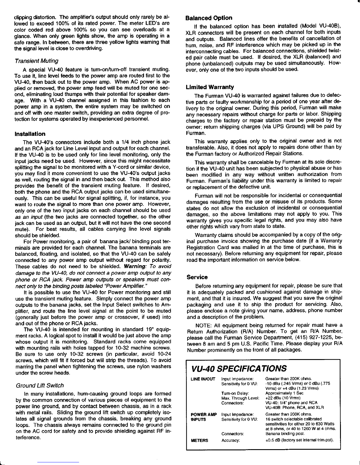
The VU-40
is comprised
of two 20 LED bar-graph meters,
cali-
brated
in dB like standard VU
meters. They may
be set with
the
pushbutton
switch on
the
left
side of
the
front
panel
to read either
Peak
(button
in)
or Average
(button
out)
response.
The
two me-
ter scales above the LED's
are used
for
Average, while
the two
scales
below
are
for Peak.
Because
audio signals are AC
(alter-
nating current), their actual voltage level
varies from millisecond
to
millisecond.
"Average"
refers
to the average magnitude during
a time span of about
1/4
second. To approximate
the action
of a
traditional
electromechanical VU
meter, choose
the Average
set-
ting. Average
also
gives
a
good
indication
of the
perceived
loud-
ness of the signal. The Peak
setting indicates
the
highest
point
of
the
waveform, regardless
of the average. Therefore,
the Peak
position
will
always result in higher readings,
but it will
give
a truer
indication
of
how
close the signal is
to clipping.
Rear Panel
The Input
Select switches
on the rear-panel
select either Line
(line
level) or Amplifier
(power
output),
allowing
you
to monitor
ei-
ther the
inputs
or outputs, respectively,
of a
power
amp. Since
each channel may be switched independently,
another
possibility
is to use one VU-40
channelfor input
and the other for output.
Of
4-9532
course, the
Line setting
may be used to
monitor
any
line level
sig-
nal, even
if no
power
amp
is involved.
For
Line, the
"zero"
meter
positions
may be set
to either
-10,
0, or
+4 dBu with the Line Input
slide switch.
This
switch
controls both the
left and right channels
(assuming
both are set to
the Line
position
with
their
Input
Select
switches).
For line
level metering,
refer
to the
white
scales on the
front
panel,
which are
calibrated in decibels.
The
choice of
-10,
0,
or
+4 depends on the
nominal
line level
of the
other
equipment
in
your
system, especially
the
mixer
and
tape recorder. lf in doubt,
consult the manuals
for that equipment.
When either or
both of the
Input
Select switches
are set to
Amplifier, the
VU-40
is ready to monitor the output(s) of a
power
amp.
The blue scales,
calibrated
in
percent
of
full
power,
are
used.
There are
16
power
output choices
from 20 to
630
watts for
8 ohm
loads,
or
f rom 40 to
'1260
watts tor 4 ohm loads. Check
the
maximum
power
output
for
your
amplifier
and the rated impe-
dance
of
your
speakers
to determine
which range
to
use. The
ex-
act wattage corresponding
to
100
percent
is determined by the
settings of
the four
Amplifier Power switches, according to the
fol-
lowing table. The switches
are shown as seen
at
the
rear
panel,
from left
(closest
to
Power Amp binding
posts)
to
right.
In adjusting system
levels, the
VU-40's meters
serve
as a
guide
to avoid overdriving
the
power
amplifier,
which
can
result in
Amplifier
Power
Switches
When
switches
are set as
follows:
The 100o/o reading in watts i,
Left
down down
down
up down
down
down up down
up up down
down down up
up
down up
down up
up
up up up
down down
down
up down
down
down up
down
up up down
down down
up
up down up
down up up
up
up up
Right Sohms
4ohms
down
20 40
down
25 50
down 32 64
down
40
80
down 50
100
down
63 126
down
80 160
down 100
200
up
125 250
up
160 32O
up
20O 400
up
250 500
up
320
640
up
400
800
up
500
1000
up
630
1260
960020-609
Page 2
clipping
distortion.
The amplifie/s
output
should
only
rarely
be al-
lowed to exceed
1000/"
of
its rated
power.
The meter LED's
are
cofor coded
red
above
100% so
you
can see overloads
at a
glance.
When only
green
lights
show,
the
amp is operating
in a
safe
range.
In between,
there are
three
yellow
lights
warning that
the
signal
level is
close
to overdriving.
Transient
Muting
A special
VU-40 feature is turn-on/turn-off
transient
muting.
To use
it, line
level feeds to the
power
amp
are routed
first
to
the
VU-40, then
back
out to the
power
amp.
When AC
power
is ap-
plied
or
removed, the
power
amp
feed will be
muted for one sec-
ond,
eliminating
loud thumps
with their
potential
for speaker
dam-
age.
With a
VU-40 channel assigned
in this
fashion to each
power
amp
in a system, the
entire system
may
be
switched on
and off
with one
master switch,
providing
an extra degree of
pro-
tection
for
systems
operated
by
inexperienced
personnel.
lnstallation
The
VU-40's
connectors
include both a
1/4 inch
phone
jack
and
an
RCA
jack
for
Line
Level input
and
output
for each
channel.
lf the
VU-40
is to be
used only
for line level monitoring, only
the
input
jacks
need be used.
However, since
this
might necessitate
splitting
the
signal
to be
monitored with a
Y-cord or similar device,
you
may
find it more
convenient
to use the
VU-40's output
jacks
as well,
routing the signal
in and then back
out. This
method
also
provides
the benefit
of the
transient
muting feature.
lf desired,
both the
phone
and the
RCA
output
jacks
can
be used simultane-
ously.
This can
be useful
for signal splitting,
if, for instance,
you
want to
route the signal
to
more than one
power
amp. However,
only one
of the two
input
jacks
on each channel
should be used
as
an
input
(the
two
jacks
are connected together,
so the other
jack
can
be used
as an output,
but
it
will
not have the one second
mute).
For best
results, all cables carrying
line level
signals
should
be shielded.
For
Power monitoring, a
pair
of banana
jacV
binding
post
ter-
minals
are
provided
for each channel.
The banana terminals are
balanced,
floating, and
isolated, so that the
VU-40
can
be
safely
connected
to any
power
amp output without
regard for
polarity.
These cables
do not
need to be shielded.
Warning: To
avoid
damage
to the
VU-40, do not connect a
power
amp output to any
phone
or
RCA
jack.
Power
amp outputs
or speakers must con-
nect only
to the binding
posfs
labeled
"Power
Amplifier."
It is
possible
to use the
VU-40 for Power monitoring and still
use the
transient
muting feature. Simply
connect the
power
amp
outputs to
the banana
jacks,
set the
lnput
Select
switches to Am-
plifier,
and
route the
line level signal at the
point
to be
muted
(generally
just
before the
power
amp or crossover,
if
used)
into
and out
of the
phone
or
RCA
jacks.
The
VU-40 is intended
for mounting in standard
19"
equip-
ment
racks. A logical spot to
install it would be
just
above the
amp
whose output
it is monitoring. Standard
racks
come equipped
with mounting
rails with
holes
tapped
for 10-32 machine screws.
Be
sure
to use
only 10-32 screws
(in pailicular,
avoid 10-24
screws,
which
will fit if forced but will strip the threads).
To avoid
marring the
panel
when
tightening
the screws, use
nylon washers
under
the screw
heads.
Ground
Lift Switch
In many
installations, hum-causing
ground
loops
are
formed
by the
common connection
of various
pieces
of equipment to
the
power
line
ground,
and by contact between chassis, as
in a rack
with metal
rails. Sliding the
ground
lift
switch
up completely
iso-
lates
all
signal
grounds
from the chassis, breaking
any
ground
loops.
The
chassis
always
remains
connected
to the
ground pin
on the
AC cord
for
safety
and to
provide
shielding
against RF
in-
terference.
Balanced
Option
lf the balanced
option
has
been
installed
(Model
VU-408)'
XLR connectors
will
be
present
on
each
channel
for both
inputs
and
outputs.
Balanced
lines offer
the
benefits
of
cancellation
of
hum,
noise,
and
RF
interference
which
may
be
picked
up
in
the
interconnecting
cables.
For balanced
connections,
shielded
twist-
ed
pair
cable
must
be
used.
lf
desired,
the
XLR
(balanced)
and
phone (unbalanced) outputs
may be
used simultaneously.
How-
ever, only
one of
the
two
inputs
should
be used.
Limited
Warranty
The
Furman
VU-40
is
warranted
against
failures
due to
defec-
tive
parts
or faulty
workmanship
for a
period
of one
year
after de-
livery to the
original
owner.
During this
period,
Furman
will make
any
necessary
repairs
without charge
for
parts
or
labor- Shipping
charges
to the
factory
or
repair station
must
be
prepaid
by the
owner;
return shipping
charges
(via
UPS Ground)
will be
paid
by
Furman.
This
warranty
applies
only
to the
original
owner
and
is not
transferable.
Also,
it does'not
apply
to repairs
done
other than
by
the
Furman factory
or
Authorized
Repair Stations.
This warranty
shall be
cancelable
by
Furman at
its sole discre-
tion
if the
VU-40
unit
has been
subjected
to
physical
abuse
or
has
been
modified
in any
way
without
written
authorization
from
Furman.
Furman's
liability
under
this
warranty
is limited
to repair
or
replacement
of
the defective
unit.
Furman
will
not be
responsible
for incidental
or consequential
damages
resulting
from the
use or
misuse of
its
products.
Some
states
do not
allow the
exclusion
of incidental
or consequential
damages,
so
the above
limitations
may
not apply to
you.
This
warranty
gives you
specific
legal
rights, and
you
may also
have
other
rights
which
vary from state
to state.
Warranty
claims
should
be accompanied
by a copy
of the orig-
inal
purchase
invoice
showing
the
purchase
date
(if
a
Warranty
Registration
Card
was
mailed
in
at
the time
of
purchase,
this is
not
necessary).
Before
returning any equipment
for repair,
please
read the
important
information
on service
below.
Service
Before
returning
any equipment
for repair,
please
be sure that
it
is adequately
packed
and
cushioned
against
damage
in
ship-
ment, and
that
it is insured.
We suggest
that
you
save the
original
packaging
and
use
it to ship
the
product
for servicing.
Also,
please
enclose
a
note
giving your
name,
address,
phone
number
and
a description
of the
problem.
NOTE: All
equipment
being
returned
for
repair must
have a
Return
Authorization
(R/A)
Number.
To
get
an
R/A Number,
pfease
call
the
Furman Service
Department,
(415)
927-1225,
be-
tween
8
am and 5
pm
U.S.
Pacific
Time.
Please display
your
R/A
Number
prominently
on
the
front of all
packages.
VU-40 SPECIFICATIONS
LINE
IwOUT
Input
lmpedance:
Greater than
200K
ohms.
Sensitivity
for 0
VU:
-10
dBu
(.245
Vrms) or 0
dBu
(.775
Vrms) or
+4 dBu
(1.23
Vrms)
Turn-on Delay:
APProximatelY 1 Sec
Max.
Through Level:
+22 dBu
(10
Vrms)
Connectors:
VU-40: 1/4"
phone
and
RCA
VU-40B:
Phone, RCA, and
XLR
POWER
AMP Input
lmpedance:
Greater
than
200K ohms.
INPUTS
Sensitivity
for 0
VU:
16
switch
selectable
calibrated
sensitivities
for
either
20 to 630
Wafts
at 8 ohms,
or
40
to
1260 W at 4 ohms
Connectors:
Banana binding
Post.
METERS
Accuracy:
+0.5 dB
(factory
set
internal trim
pot).
 Loading...