

Page 1
AC Power Conditioner
O w n e r ’ s M a n u a l
IN T R O D U C T I ONS FEATURES DESCRIPTION INSTALLATION SAFETY SPECS
Page 2

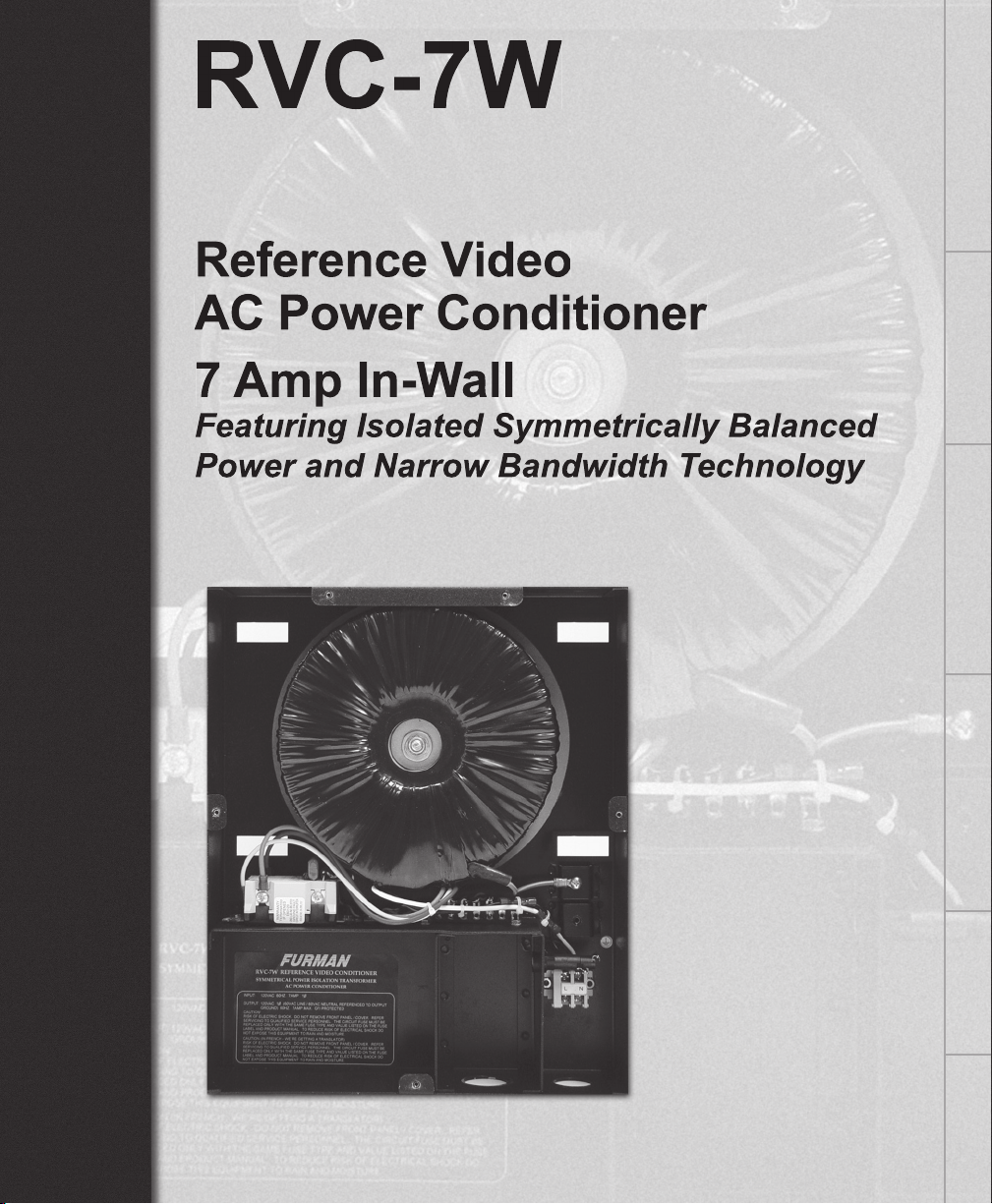
RVC-7W
- 2 -
The
is a no-compromise,
no-expense-spared design, with painstak-
ing attention paid to every component.
ing them from transient voltage surges.
power regulating and conditioning line of
professionals for more than 28 years.
all video frequencies up to 1 GHz.
suppression protects your valuable equip-
service calls.
exceeds the current demands of the largest
the isolated output eliminates potential AC
accepts any house paint chosen by interior
decorators.
The specially constructed toroidal trans-
former is the fi nest available, yielding
extremely low magnetic fi eld leakage, and
of load or AC source contamination.
tacles are individually ground fault (GFCI)
I N TRODU C T I O N F E A T U R E S DESCRIPTION INSTALLATION SAFETY SPECS
Page 3

RVC-7W
- 3 -
The RVC-7W’s isolated symmetrically bal-
anced power ensures no ground contamina-
tion from your incoming line will affect your
fi ltered AC power, as it is totally isolated. This
total isolation of both ground and incoming
AC power means your critical video reproduc-
tion will not suffer AC hum bars, RF, or EMI
These distortions occur when AC power is
shared throughout a building or home. They
VAC Neutral - reference to output Ground at
and magnetic fi elds from penetrating or radiat-
video components. Additionally, the RVC-7W’s
virtually maintenance free TVSS circuitry, as-
sure electrical safety, and protectionof your
valued video component.
and packing materials for any obvious dam-
age. If internal damage is likely, contact the
damage is evident, contact the carrier. Save
all shipping and packing materials. You may
factory for service. The box should contain
the RVC-7W unit, Left and Right (L - type)
out and return your warranty registration card.
source (wiring) to which a RVC-7W is con-
Wiring to the RVC-7W’s AC input terminal
should have proper safety listing and meet
the electrical codes for your area. If in doubt,
to the walls wooden studs with the supplied
#10 screws. When properly placed, the main
will easily support the RVC-7W’s weight. The
I N T R O D U C T I O N F E A T U R E S DESCRIPTION INSTALLATION SAFETY SPECS
Page 4

RVC-7W
- 4 -
that the
back
surface of the unit’s
panel is
fl ush with the outside surface of the wall, and
the panel covers the wall cut-out. Because of
the Reference Series’ low-fl ux density trans-
former design, placement or proximity to a
tened to wall studs on either side of the RVC-
of the chosen mounting location be precisely
2. We have supplied a cut-out template
aid sheet-rock installers for new construction.
wall mount bracket, pay attention to the verti-
front panel will accept any household paint to
further aid in your installation, make sure that
the RVC-7W’s signal wire and AC output cable
are supplied with each RVC-7W, and are also
supplied as a separate accessory (HRKIT-
4. Now it’s time to mark the position of the pilot
struction it’s easier, however you MUST know
the exact depth of the wall material, (1/2” or 5/8”
adjustment from back to front. Both have hole
screw pilot holes will be relatively simple. Once
you’ve determined where the vertical center of
your RVC-7W and or fl at screen will be, mark
the studs with a level to show your center line
the short side facing out). This can be done
with retrofi t installation as well, after the rect-
angular cutout has been made (a fl ash light or
stand mounted light may be necessary to see
6. Mark a horizontal line 1/4” below the center
the vertical pilot hole positions for the RVC-
vertical marks that will determine depth. For
depth or material thickness of the sheet rock,
sheet rock is most common, and it’s usually
I N T R O D U C T I O N F E A T U R E S DESCRIPTION INSTALLATION SAFETY SPECS
Page 5

RVC-7W
- 5 -
two scenarios for you. For new construction,
the depth marks for the #10 screw pilot hole
are: (See fi g. 2)
- for 1/2” wall thick-
outside front edge of the stud, or inside surface
of the wall that will be facing you.
or inside surface of the wall that will be facing
you.
surface.
- 1-15/16” deep from the outside
wall surface. Since the stud will be set back
from the wall cutout, it may be benefi cial to
subtract the wall thickness and space the end
of your measuring device fl ush with the inside
of the wall (assuming the devices edge starts
standard 1/2” and 5/8” wall thickness.
the installation center line is NOT drilled, it’s
only a reference marking.
We recommend a drill bit no larger in diameter
than 1/16” as most studs are a soft wood, and
these brackets must support 40lbs. In the rare
event that the studs are made of a metal mate-
CENTER
CENTER
LINE (R)
LOWER BRACKET
LINE - 1/4" BELOW
CENTER (R)
UPPER BRACKET
LINE - 5-1/4" ABOVE
CENTER (R)
WALL STUDS
FIG.1
CENTER
WALL STUDS
RIGHT SIDE
DEPTH LINE
1-5/16" FO
R
5/8" SHEET
ROCK
.
1-15/16" TOTAL
FROM OUTSIDE
EDGE OF WALL
TO DEPTH LINE.
FIG. 2
I N T R O D U C T I O N F E A T U R E S DESCRIPTION INSTALLATION SAFETY SPECS
Page 6

RVC-7W
- 6 -
ate to working with metal.
stalled. The “hooks” should be facing upwards
to support the rectangular cutouts in the rear of
the RVC-7W’s chassis.
signal and AC wiring will mount through the
sure there’s suffi cient signal wire or cabling
to pass through the bottom of the RVC-7W,
through the front panel cutout, and ultimately
typically requires less than 1ft. of wire beyond
the bottom of the chassis. However, a service
there will be plenty of space below the RVC-
ton. Use a Phillips screwdriver to remove the
and to the right should not be loosened! It is a
grounding strap screw, and is not used to attach
the front panel to the chassis. (See fi g. 3)
front panel ground strap from the chassis.
wiring through the unit yet. The purpose for
at this time is to check the alignment of the
sticking out, or is recessed too far, an adjust-
so inaccurate as to make the RVC-7W hang at
a noticeable angle clockwise or counter-clock-
wise.
I N T R O D U C T I O N F E A T U R E S DESCRIPTION INSTALLATION SAFETY SPECS
Page 7

RVC-7W
- 7 -
S
YMMETRICAL
POWER ISOLA
TION TRANSF
ORMER
A
C POWER CONDITIONER
RVC-7W R
EFERENCE VIDE
O CONDITIONER
INPUT: 120VAC 60HZ. 7AMP 1O
OUTPUT: 120VAC 1O (60VAC LINE / 60VAC NEUTRAL REFERENCED TO OUTPUT
GROUND) 60HZ. 7AMP MAX. GFI PROTECTED
CAUTION!
RISK OF ELECTRIC SHOCK. DO NOT REMOVE FRONT PANEL / COVER. REFER
SERVICING TO QUALIFIED SERVICE PERSONNEL. TO REDUCE RISK OF ELECTRICAL
SHOCK DO NOT EXPOSE THIS EQUIPMENT TO RAIN AND MOISTURE.
AVIS!
CIRCUIT COMMUN ISOLE DE LA MASSE A LA SORTIE. MEME SI LE COURANT
A
LA SORTIE EST MUNI DE PROTECTION GFI, NE JAMAIS TOUCHER LES FILS
EXPOSES
OULES PARTIES EN METAL SANS TESTER POUR LA PRESENSE DE
TENSIONS A.C.
!
ETL LISTED 3041249 CONFORMS TO ANSI/UL #1012
CERTIFIED TO CAN/CSA E335-1/3E-94
L
N
adjusted, remove the chassis and install the
are very common at any hardware or electrical
supply store, and individual installers will have
their preferences as to model and manufac-
ture. All we (and your local inspector) require is
that the cable clamps be standard CSA, C-UL,
The larger hole on the bottom surface is for the
signal wiring and cables. It requires a 1” con-
duit cable clamp. The smaller hole to the right
to neatly dress these wires and cables. There is
dress the signal wiring through the large clamp,
and the A.C. wiring through the small clamp.
this operation, or place it on a stand or table im-
the incoming AC wiring be DISENGAGED dur-
this switch must be at least 3 m.m. (virtually all
switched circuit breakers will meet this criteria).
dressing, and installing these wires!
secured by the clamps, place the chassis on the
the Neutral wire into the A.C. terminal block
a slotted screwdriver. Place the Line wire into
the A.C. terminal block marked “L”, (bottom
opening) and secure with a slotted screwdriver.
The ground wire must be surely fastened to
the green 10-32 slotted screw on the bottom.
A listed ring lug, appropriate for the wire gauge
wire around the screw is acceptable in some
I N T R O D U C T I O N F E A T U R E S DESCRIPTION INSTALLATION SAFETY SPECS
Page 8

RVC-7W
- 8 -
your area. Make sure all three wires are se-
tachable A.C. cord to the GFI outlet (this is to
20. Connect the ground strap from the front
of the input ground screw. Make sure this is
secure, as it is for both safety and R.F. shield-
ground connection is compromised, the noise
attenuation will suffer. Now, re-attach the front
21. Go to the electrical panel and switch the
the GFI outlet, and will be visible when you
front panel.
22. If you are using the RVC-7W for a projec-
tor, you’re fi nished! However, if you are mount-
from the wall surface .076” (approximately
will have center sections that press fl ush to
the RVC-7W’s front panel, we have included
of the front panel, when securing the plasma
As the RVC-7W incorporates Isolated Sym-
to guard against catastrophic failure in Refer-
ence components. Under normal conditions,
the addition of Furman’s Isolated Symmetrical
Technology, any form of electrical shock (under
ed a GFCI (ground fault interrupter). This GFCI
will immediately disconnect the output voltage
when it detects an excess of fi ve milliamps cur-
This ensures that even if your lcd, plasma, or
there will be no possibility of electric shock
the RVC-7W.
occasionally possible to false trip the GFCI if
additional fi lters with unacceptable levels of
designs can actually create as much noise as
they attempt to reduce, we recommended they
just press the reset tab in the center of the
I N T R O D U C T I O N F E A T U R E S DESCRIPTION INSTALLATION SAFETY SPECS
Page 9

RVC-7W
- 9 -
to your systems components. The GFCI is
anti-chamber located on the RVC-7W’s lower
you do not wish to remove it, the eraser side of
a pencil can easily reset the GFCI. When the
tab is properly reset, the blue AC output indi-
voltage to the unit).
The RVC-7W is capable of suppressing virtu-
ally any instantaneous voltage surge. However,
the protection device may be damaged if the
over-voltage spike is sustained and extreme,
switch will not stay in the “on” position. If this
though typically this will not be necessary.
and operating instructions before the
service and installation professionals.
a switched electrical panel that has been
disengaged.
enter the unit.
standards for use of Balanced A.C. Power,
we recommend that the RVC-7W be limited
to use with video equipment, and screen art
accessories.
The RVC-7W should be serviced by qualifi ed
service personnel when:
treme moisture.
ground be utilized from the source AC power
to the input of the Reference unit. This ground
without the incoming safety ground is consid-
ered improper operation and will invalidate the
warranty.
I N T R O D U C T I O N F E A T U R E S DESCRIPTION INSTALLATION SAFETY SPECS
Page 10

RVC-7W
- 10 -
WARRANTY
Furman Sound, Inc. warrants to the original purchaser of
free from defects in material and workmanship for a period
at the Furman website. If the purchaser fails to complete
reduced to one year from the date of purchase.
purchaser shall notify Furman in writing of the claimed
be covered by this warranty, Furman shall authorize the
purchaser to return the product to the Furman factory or
should be accompanied by a copy of the original purchase
invoice showing the purchase date; this is not necessary if
in the completed warranty card or by registering on-line
at the Furman website. Shipping charges to the Furman
factory or to an authorized repair location must be prepaid
by the purchaser of the product. Furman shall, at its own
ment that is damaged by transient voltage (an “Occur-
rence”) while properly connected through the Furman
Equipment Warranty is limited to the amount of the deduct-
ible on the Purchaser’s personal property insurance policy
Equipment Warranty, the Purchaser must forward a copy
aged equipment to Furman and complete the Furman
right to review the damaged Furman product, the damaged
man for inspection shall be borne solely by the Purchaser.
Damaged equipment must remain available for inspec-
All warranties contained herein are null and void if: the Fur-
man Surge Protector in use during the occurrence is not
provided to Furman for inspection upon Furman’s request
at the sole expense of the Purchaser, Furman determines
properly installed, altered in any way or tampered with,
Furman determines that the damage did not result from
Furman determines that the connected equipment was not
ment. All Furman Surge Protectors must be plugged di-
rectly into a properly wired AC power line with a protective
ground and must not be “daisy-chained” together in serial
fashion with other power strips, UPS’s, other surge protec-
such installation voids this warranty. The Furman warranty
ment where Furman has determined, at its sole discretion,
not protect against acts of God (other than lightning) such
as fl ood, earthquake, war, terrorism, vandalism, theft,
normal-use wear and tear, erosion, depletion, obsoles-
product in anyway with a generator, heater, sump pump,
automobile, motorcycle, or golf-cart battery charger. To
be used indoors only and in dry areas. All warranties con-
NOT LIMITED TO THE IMPLIED WARRANTIES OF
PURPOSE. Furman does not warrant against damages
from improper installation, against defects in products or
I N T R O D U C T I O N F E A T U R E S DESCRIPTION INSTALLATION SAFETY SPECS
Page 11

RVC-7W
- 11 -
ages resulting from such non-Furman made products or
at its sole discretion if the product is modifi ed in any way
also does not apply to products upon which repairs have
been affected or attempted by persons other than pursuant
fective product in the manner and for the period provided
above. Furman shall not have any other obligation with
respect to this product or any part thereof, whether based
sentatives’ ORAL OR OTHER WRITTEN STATEMENTS
DO NOT CONSTITUTE WARRANTIES, shall not be relied
sale or this limited warranty. This Limited Warranty states
a Warranty Registration Card was mailed in at the time of
purchase or if the product was registered on-line, this is
not necessary). Before returning any equipment for repair,
please be sure it is adequately packed and cushioned
against damage in shipment, and that it is insured.
that it is insured. We suggest that you save the
original packaging and use it to ship the product
for servicing. Also, please enclose a note giving
your name, address, phone number and a de-
scription of the problem.
To get an R/A Number, please call the Furman
or 121, between 8 a.m. and 5 p.m., U.S. Pacifi c
Time. Please display your R/A Number promi-
I N T R O D U C T I O N F E A T U R E S DESCRIPTION INSTALLATION SAFETY SPECS
Page 12

RVC-7W
- 12 -
Web: www.furmansound.com
draw Outlets: 2 (Isolated Symmetrical Balanced A.C.
outlets) Protection: GFCI circuit protection for all AC
outlets
Transient Voltage
Surge Suppression: Stand-off Voltage 200V Maximum Clamping Voltage
324V 10/1000 – 65,000 Watts @ 20uS. Test = 300,000
Watts Peak Power Handling
Overall (installed): 3.45” (from outside front panel) 3.375” from out side
wall surface
Weight: 42 lbs. (without brackets) Weight in shipping carton
Agency Listing: C-ETL to U.L. standard #1012
I N T R O D U C T I O N F E A T U R E S DESCRIPTION INSTALLATION SAFETY SPECS
 Loading...