

Page 1
1
Page 2

Contents
Introduction ...................................................................................................................................3
Features .........................................................................................................................................3
Warnings ....................................................................................................................................4
Description ....................................................................................................................................5
Q-1311 Front Panel Controls ........................................................................................................6
Q-1311 Rear Panel Connections .................................................................................................6
Q-1312V Front Panel Controls .....................................................................................................6
Q-1312V Rear Panel Connections ..............................................................................................6
Q-2312 Front Panel Controls ........................................................................................................7
Q-2312 Rear Panel Connections .................................................................................................7
Q-2151 Front Panel Controls ........................................................................................................7
Q-2151 Rear Panel Connections .................................................................................................7
Q-2152V Front Panel Controls .....................................................................................................8
Q-2152V Rear Panel Connections ..............................................................................................8
Descriptions of Controls ...............................................................................................................8
Front Panel .................................................................................................................................8
Rear Panel ...............................................................................................................................10
Operational Overview ...............................................................................................................11
Installation ...................................................................................................................................12
Available Accessories ...............................................................................................................12
Three Year Limited Warranty .....................................................................................................13
Service .........................................................................................................................................14
Specifications .............................................................................................................................15
2
Page 3

Introduction
Congratulations on your purchase of a Furman Sound Q-Series Graphic Equalizer. You
have chosen an instrument which offers outstanding features, superior performance,
and unequalled versatility in shaping the tone of your musical, vocal and audio program
material. As with all Furman products, the Q-Series Graphic Equalizers are used in highend sound reinforcement, broadcasting, recording, audio for video and film production,
DJ systems, musical instrument amplification, and even audiophile home stereo
applications.
Even if you are an experienced audio professional, please take a few moments to read
this brief manual. It will help you get the most out of your Q-Series Equalizer.
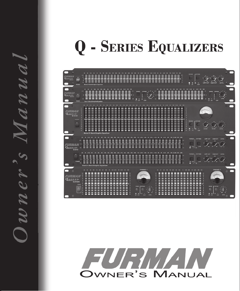
This manual covers five models:
Q-2151: Dual 15-band, single rack space
Q-1311: Single 31-band, single rack space
Q-2312: Dual 31-band, double rack space
Q-2152V: Dual 15-band, long-throw sliders, VU meters, double rack space
Q-1312V: Single 31-band, long-throw sliders, VU meter, double rack space
Features
• Constant-Q response for maximum graphic accuracy.
• Versatile connectivity via XLR, balanced 1/4” phone, and RCA inputs and outputs.
• High-performance, detented sliders
• ISO 1/3 octave (Q-1311, Q-1312V, Q-2312) or 2/3 octave (Q-2151, Q-2152V)
frequency bands.
• Superior common-mode rejection.
• Heavy-duty, shielded power supply to assure cool and reliable operation.
• Integrated ground lift for quiet operation.
• Selectable ±6dB or ±12dB range switches with LED indicators for precision operation.
• Bypass switch with LED indicator.
• Overload “Clip” LED warning indicator.
3
Page 4

• Output level control.
• Rugged all steel construction.
Warnings
Environment
Never place this product in an environment that could alter its performance or reduce
its service life. Such environments are usually characterized by high levels of heat, dust,
moisture, or vibration.
Safety
1. Read and follow all instructions carefully.
2. Do not operate this apparatus near water.
3. Clean only with a damp cloth.
4. Install only in accordance with the instructions in this manual.
7. Do not defeat the safety purpose of the polarized or grounding type plug. A polarized
plug has two blades, with one wider than the other. A grounding type plug has two
blades and a third grounding prong. The wide blade or the third prong is provided for
your safety. If the provided plug does not fit into your outlet, consult an electrician for
replacement of the obsolete outlet.
8. Protect the power cord from being walked on or pinched, particularly at plugs,
convenience receptacles, and the point where it is attached to the apparatus.
9. Unplug this apparatus during lightning storms or when unused for long periods of
time. For complete protection against lightning strikes and related hazards, a more
sophisticated protection device is needed, such as the Furman PRO Series Power
Conditioners, or the AR-Series AC Line Voltage Regulators.
10. Refer all servicing to qualified service personnel. Servicing is required when the
apparatus has been damaged in any way, such as power supply cord or plug is
damaged, liquid has been spilled or objects have fallen into the apparatus, the
apparatus has been exposed to rain or moisture, does not operate normally, or
has been dropped.
4
Page 5

Description
The Q-2151 is a dual channel 15-band equalizer, using short-throw 20mm sliders and
housed in a single rack space chassis.
The Q-1311 is a single channel 31-band equalizer, using short-throw 20mm sliders and
housed in a single rack space chassis.
The Q-2312 is a dual channel 31-band equalizer, using short-throw 20mm sliders and
housed in a two rack space chassis.
The Q-2152V is a dual channel 15-band equalizer, using long-throw 60mm sliders and a
highly accurate VU meter, housed in a two rack space chassis. It is suitable for the most
critical applications.
The Q-1312V is a single channel 31-band equalizer, using long-throw 60mm sliders and a
highly accurate VU meter, housed in a two rack space chassis. It is suitable for the most
critical applications.
All Q-series equalizers feature precision engineered controls for unparalleled accuracy.
The sliders on all units have a smooth, silky feel, with electronically accurate center
detents.
All 31-band equalizers incorporate high cut control from 3kHz to 40kHz, and low cut
control from 10Hz to 250Hz. This extended range offers unequalled control over the
extreme ends of the audio spectrum.
5
Page 6

Q-1311 Front Panel Controls
Q
-
1
3
1
1
14
13
10
12
11
Q
-
1
3
1
2
V
9
14
13
10
12
11
Q-1311 Rear Panel Connections
Q-1312V Front Panel Controls
Q-1312V Rear Panel Connections
6
Page 7

Q-2312 Front Panel Controls
Q
-
2
3
1
2
14
13
10
12
11
Q
-
2
1
5
1
14
13
10
12
11
Q-2312 Rear Panel Connections
Q-2151 Front Panel Controls
Q-2151 Rear Panel Connections
7
Page 8

Q-2152V Front Panel Controls
Q
-
2
1
5
2
V
9
9
14
13
10
12
11
Q-2152V Rear Panel Connections
Descriptions of Controls
Front Panel
1. POWER SWITCH
This switch powers the unit on and off.
IMPORTANT: Always turn your equalizer on BEFORE turning on the power amp, and
turn the equalizer off AFTER turning off the power amp.
For convenience, it is recommended that the equalizer and any other rackmount equipment be powered through a switchable outlet box, such as the
Furman PL-8 II Power Conditioner and Light Module. The PL-8 II provides an easy
way to power up the entire rack with one front-panel switch, and provides
discreet illumination on dark stages and in the studio, as well. If you do use a
switchable outlet box, remember to leave the on-off switch in the ON position at
all times.
8
Page 9

2. FREQUENCY SLIDERS
Each slider controls the amount of boost or cut to be applied to the associated
frequency band, over a range of ±6dB or ±12dB, as selected by the Range
Selector. The center detent indicates flat response.
In the Q-2151 or Q-2152V, the interval between adjacent slider frequencies is 2/3
octave.
In the Q-1311, Q-1312V and Q-2312, the interval between adjacent slider
frequencies is 1/3 octave.
3. RANGE SELECTOR and RANGE INDICATORS
A range selector switch is provided on all of the Q-Series models, to select a
resolution of ±6dB or ±12dB for the EQ sliders. The ±6dB setting allows greater
resolution in situations where large amounts of boost or cut are not needed.
A yellow light indicates a boost and cut of +12 dB; a green light indicates a boost
and cut of + 6 dB.
4. BYPASS SWITCH and INDICATOR
The Bypass Switch is useful for quick comparison of the original sound with EQ’ed
sound, allowing the equalization signal to be bypassed for a quick “before and
after” comparison of the EQ effects. When the Bypass LED is lit the EQ is in bypass
mode. The stereo Q-2151, Q-2152V, and Q-2312 have two of these buttons
allowing either channel to be bypassed independently. Note that when the
Bypass button is activated, the Level Control is bypassed as well.
5. OVERLOAD INDICATOR
This LED lights if any of the equalizer’s circuitry approaches 5dB before clipping.
Occasional blinking of this indicator is acceptable, but if it lights continuously it is
necessary to reduce the input level, frequency boost, or the output level.
6. LOW CUT CONTROL (Q-1311, Q-1312V, and Q-2312 only)
Most audio systems cannot reproduce subsonic sounds, nor can the human ear
hear them. Yet they are often present in audio signals. If allowed to reach power
amplifiers or recording devices, they can rob power and cause distortion while
adding little, if anything, to sound quality.
The Low Cut knob allows the cutoff frequency to be set anywhere in the range
of 10Hz to 250Hz. This also makes it useful for the removal of some types of RFinduced hum. Roll off beyond the cutoff point is at 12 dB per octave.
7. HIGH CUT CONTROLS (Q-1311, Q-1312V, and Q-2312 only)
Most audio systems cannot reproduce supersonic sounds, nor can the human ear
hear them. Yet they are often present in audio signals. If allowed to reach power
9
Page 10

amplifiers or recording devices, they can rob power and cause distortion while
adding little, if anything, to sound quality.
The High Cut’s range is 3KHz to 40 KHz. Roll off beyond the cutoff point is at 12 dB
per octave.
8. LEVEL CONTROL
Adjusts the overall output volume. The combined effect of the EQ Frequency
sliders typically results in an increase or decrease of overall output level. The
Level Control can compensate for this change in level. Compare the level of the
equalized signal with that of the unequalized signal (bypass button in), and use
the Level Control to eliminate any difference in levels.
9. LEVEL METERS (Q-2152V, Q-1312V)
Each channel of the EQ is equipped with a backlit VU meter. The meter is
calibrated for “0” level equal to +4 dBu output.
Rear Panel
10. POWER CABLE
This cable is used to connect to an AC power source. For North American models,
this source shall be 115 115VAC; for export models, the source shall be 230VAC.
11. FUSE HOLDER
This holder contains the AC primary fuse. If the fuse has blown, replace with the
same size and rating. If the fuse continues to blow, refer servicing to qualified
technical personnel.
12. AC VOLTAGE SELECTOR
Set this switch to match the AC line voltage in your area.
13. GROUND LIFT SWITCH
In many installations, hum-causing ground loops are formed by the common
connection of various pieces of equipment to the power line ground, and by
contact between chassis, as in a rack with metal rails. Sliding the Ground Lift
switch up completely isolates all signal grounds from the chassis, breaking any
ground loops. The chassis always remains connected to the ground pin on the
AC cord for safety and to shield against RF interference. Try both positions of the
Ground Lift switch, and leave the switch in the position that results in the least
hum in your system.
Note: The ground lift can be rendered ineffective by 3 pin audio connectors that
tie pin 1 (signal ground) to the metal shell is optional on all 3 pin connectors, and
can be removed, if present, by opening up the connector on the cable and
10
disconnecting it.
Page 11

14. INPUTS AND OUTPUTS
The Q-Series units offer multiple input and output connectors to meet the
connectivity demands of various systems.
The 1/4” phone jack input(s) are wired with three conductors Tip-(Positive) Ring(Negative) Sleeve-(Shield) type phone jacks, You can use these inputs equally
well with either balanced or unbalanced phone plugs. For balanced connections
(XLR and 1/4” phone), shielded twisted pair cable should be used.
The RCA connectors are unbalanced, and are designed for low level input and
output.
IMPORTANT: Only one group of connectors may be used at a time.
XLR: Pin 1 = shield
Pin 2 = signal positive
Pin 3 = signal negative.
TRS: Tip = signal positive
Ring = signal negative
Sleeve = shield
RCA: Tip = signal positive
Sleeve = ground
Operational Overview
The Furman Q-series Graphic Equalizers divide the audio frequency spectrum into
segments or bands, each covering a designated frequency range. The Q-2151 and
Q-2152V utilize 15 bands, each covering 2/3 of an octave, while the Q-1311, Q-1312V,
and Q-2312 use 31bands, each covering 1/3 octave.
Each unit is equipped with a selectable range switch (3) that allows their Frequency Slider
(2) ranges to be set to ±6dB or ±12dB. Due to the short range of sliders built into a single
rack space component, their resolution is somewhat limited in the ±12dB setting. The
±6dB setting provides a more precise scale, and is suggested whenever circumstances
will allow.
The 31 band Q-Series equalizers provide Low Cut control that can be adjusted over a 10
to 250 Hz range and a High Cut control that ranges from 3K to 40 KHz. Having adjustable
filter cutoff points allows the response to be customized for the particular type of audio
program and the types of noise or interference likely to be encountered. If you do
not wish to use the Low and High Cut filters, leave the knobs set to 10 Hz and 40 KHz,
respectively, for minimum effect.
11
Page 12

Keep in mind that in most cases, cutting offending frequencies is preferable to boosting
other frequencies.
Constant-Q
An important Q-series feature is a sophisticated design that achieves constant-Q
equalization curves. The letter “Q” is a mathematical symbol for bandwidth. Constant
bandwidth means that the bandwidth does not change as the amount of boost or cut is
varied.
Installation
The Q-Series units are intended for mounting in standard 19” equipment racks. Standard
racks come equipped with mounting rails with holes tapped for 10-32 machine screws.
Be sure to use only 10-32 screws. To avoid marring the panel when tightening the screws,
use nylon washers under the screw heads. For best results, all connecting cables should
be shielded. Balanced connections should use shielded, twisted-pair cable.
If the Q-Series unit is not permanently installed in a system, but is available to be used
when and where needed, it may be most convenient to wire the system with a Patch
Bay such as the Furman PB-48. Then, each EQ channel can be easily patched into as
needed. Each EQ input/output pair should be connected to a vertical pair of jacks on
the patch bay. The “normal” jumper on that patch bay circuit board should be cut so
that the input and output are not connected when the channel is not in use.
Available Accessories
Furman Models SC-1, SC-2 Universal Security Covers
These attractive black anodized aluminum covers install over the front panel of any rackmount equipment.
SC-1 is for single rack unit equipment (1.75” height) such as the Q-2151 or Q-1311, while
SC-2 is for double rack unit equipment like the Q-1312V, or Q-2312, or two singles.
Their purpose is to prevent unauthorized tampering with the controls of permanently
installed units. This is especially important when room equalization settings have been
carefully and precisely established, yet the equalizer or equalizers themselves must be
in a location where the controls could be deliberately or accidentally changed. When
changes are necessary, the covers may be removed with a screwdriver without
dismounting the underlying equipment from the rack.
12
Page 13

Three Year Limited Warranty
Furman Sound, Inc., having its principal place of business at 1997 South McDowell Blvd.,
Petaluma, CA 94954 (“Manufacturer”) warrants its Q-Series Equalizers (the “Product”) as
follows:
Manufacturer warrants to the original Purchaser of the Product that the Product sold
hereunder will be free from defects in material and workmanship for a period of three
years from the date of purchase. The Purchaser of the product is allowed fifteen days
from the date of purchase to complete warranty registration by mail or on-line at the
Furman website. If the Product does not conform to this Limited Warranty during the
warranty period (as herein above specified), Purchaser shall notify Manufacturer in
writing of the claimed defects. If the defects are of such type and nature as to be
covered by this warranty, Manufacturer shall authorize Purchaser to return the Product to
the Furman factory or to an authorized Furman repair location. Warranty claims should
be accompanied by a copy of the original purchase invoice showing the purchase
date; this is not necessary if the Warranty Registration was completed either via the
mailed in warranty card or on-line website registration. Shipping charges to the Furman
factory or to an authorized repair location must be prepaid by the Purchaser of the
product. Manufacturer shall, at its own expense, furnish a replacement Product or, at
Manufacturer’s option, repair the defective Product. Return shipping charges back to
Purchaser will be paid by Manufacturer.
THE FOREGOING IS IN LIEU OF ALL OTHER WARRANTIES, EXPRESS OR IMPLIED, INCLUDING
BUT NOT LIMITED TO THE IMPLIED WARRANTIES OF MERCHANTABILITY AND FITNESS FOR
A PARTICULAR PURPOSE. Manufacturer does not warrant against damages or defects
arising out of improper or abnormal use of handling of the Product; against defects or
damages arising from improper installation, against defects in products or components
not manufactured by Manufacturer, or against damages resulting from such nonManufacturer made products or components. This warranty shall be cancelable by
Manufacturer at its sole discretion if the product is modified in any way without written
authorization from Furman Sound. This warranty also does not apply to Products upon
which repairs have been affected or attempted by persons other than pursuant to
written authorization by Manufacturer.
THIS WARRANTY IS EXCLUSIVE. The sole and exclusive obligation of Manufacturer shall be
to repair or replace the defective Product in the manner and for the period provided
above. Manufacturer shall not have any other obligation with respect to the Products or
any part thereof, whether based on contract, tort, strict liability or otherwise. Under no
circumstances, whether based on this Limited Warranty or otherwise, shall Manufacturer
be liable for incidental, special, or consequential damages. Manufacturer’s employees
or representatives’ ORAL OR OTHER WRITTEN STATEMENTS DO NOT CONSTITUTE
WARRANTIES, shall not be relied upon by Purchaser, and are not a part of the contract
for sale or this limited warranty. This Limited Warranty states the entire obligation
13
Page 14

of Manufacturer with respect to the Product. If any part of this Limited Warranty is
determined to be void or illegal, the remainder shall remain in full force and effect.
Service
Before returning any equipment for repair, please be sure that it is adequately packed
and cushioned against damage in shipment, and that it is insured. We suggest that you
save the original packaging and use it to ship the product for servicing. Also, please
enclose a note giving your name, address, phone number and a description of the
problem.
NOTE: All equipment being returned for repair must have a Return Authorization (RA)
Number. To get an RA Number, please call the Furman Service Department:
(707) 763-1010, ext. 121.
Please display your RA Number prominently on the front of all packages.
14
Page 15

Specifications
OUTPUTS
Type Active Balanced/Unbalanced
Connectors 3-Pin XLR,1/4” TRS,RCA (Unbal.)
Impedance Typ.<150 Ohms
Maximum Level +22dBm(2KΩ)
+18dBm(600 Ohms)
OVERALL GAIN RANGE Off to +6dB(Unbal), sliders centered
Off to +12dB(Bal), sliders centered
RFI Filters Yes
Passive Bypass Switches Yes
Overload LED Threshold 5 dB(Below Clipping)
Low Cut Filter 10-25Hz,12dB/Oct
High Cut Filter 3k-40kHz,12dB/Oct
Frequency Response 20Hz-20kHz,+0.5dB
THD +Noise .01%(20Hz-40kHz+10dBu)
IM Distortion(SMPTE) 0.005%
Signal-to-Noise Ratio -94dB(20kHz Noise Bandwidth)
Channel Separation 50dB(1kHz)
Common Mode Rejection 50:1
LINE VOLTAGE
190-250VAC,50Hz
AC Power Consumption 12W
Construction All Steel
Dimensions
Q-2312, Q-2152, Q-1312 3.5in (H) x 19in (W) x 8.5in (D) (2RU)
8.9cm x 48.3cm x 21.6cm
Q-1311, Q-2151 1.75in (H) x 19in (W) x 8.5in (D) (1RU)
WEIGHT
Q-2312, Q-2152, Q-1312 9lbs.(4.1kg)
Q-1311, Q-2151 4.51bs.(2.5kg)
95-130VAC,50/60Hz
4.45cm (H) x 48.3cm (W) x 21.6cm(D)
Specifications and design subject to change without notice for improvements.
15
Page 16

100104 - A
16
Furman Sound, Inc.
1997 South McDowell Blvd.
Petaluma, California 94954-6919 USA
Phone: 707-763-1010
Fax: 707-763-1310
Web: www.FurmanSound.com
E-mail: info@FurmanSound.com
 Loading...