

Furman POWERKIT-TL Installation Instructions Manual
Furman POWERKIT-TL Installation Instructions
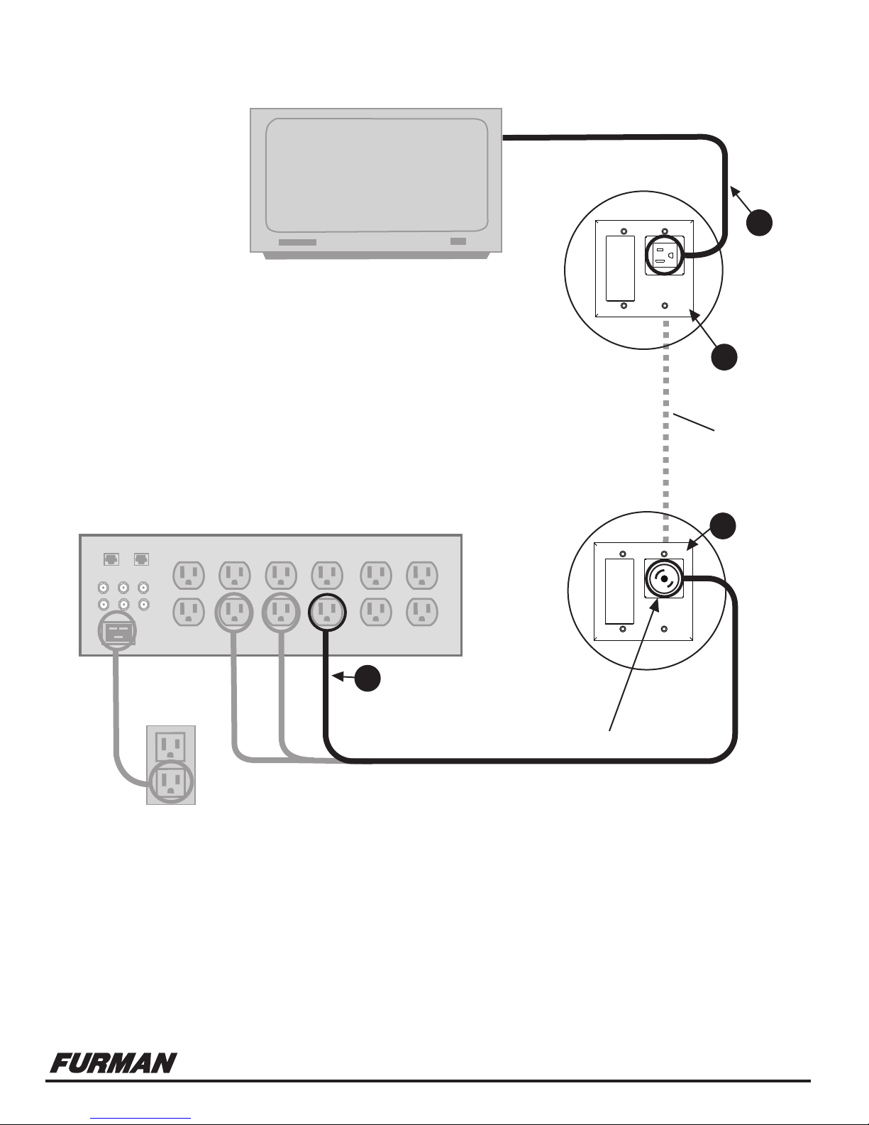
Remote Display Device
(Plasma TV, DLP, etc.)
POWERKIT-TL A four part kit designed specifically
to provide the ultimate power solution to remote
display devices within a home theater system.
4
MPC-IEC
POWER CORD
POWER
3
OUTLET
FACEPLATE
Inwall
Romex
(not included)
FURMAN POWER CONDITIONER
2
POWER
INLET
FACEPLATE
1
AC POWER CORD WITH TWISTLOCK CONNECTOR
Plug into any receptacle for customized filtration needs.
1. AC POWER CORD: This 10 ft. power cord is engineered to provide optimum power transfer, and shield-out performance robbing noise.
2. POWER INLET FACEPLATE: The unique twist-lock connector mates with the AC POWER CORD to provide a safe, secure and
listing agency compliant installation. The modular signal connection allows for a variety of installation options.
3. POWER OUTLET FACEPLATE: This modular interface has added noise filtration to eliminate any unwanted radiated interference.
4. POWER CORD (MPC-IEC): 24 inch IEC power cord.
1690 Corporate Circle, Petaluma, CA 94954 • Fax 707-763-1310 • www.FurmanSound.com
080206
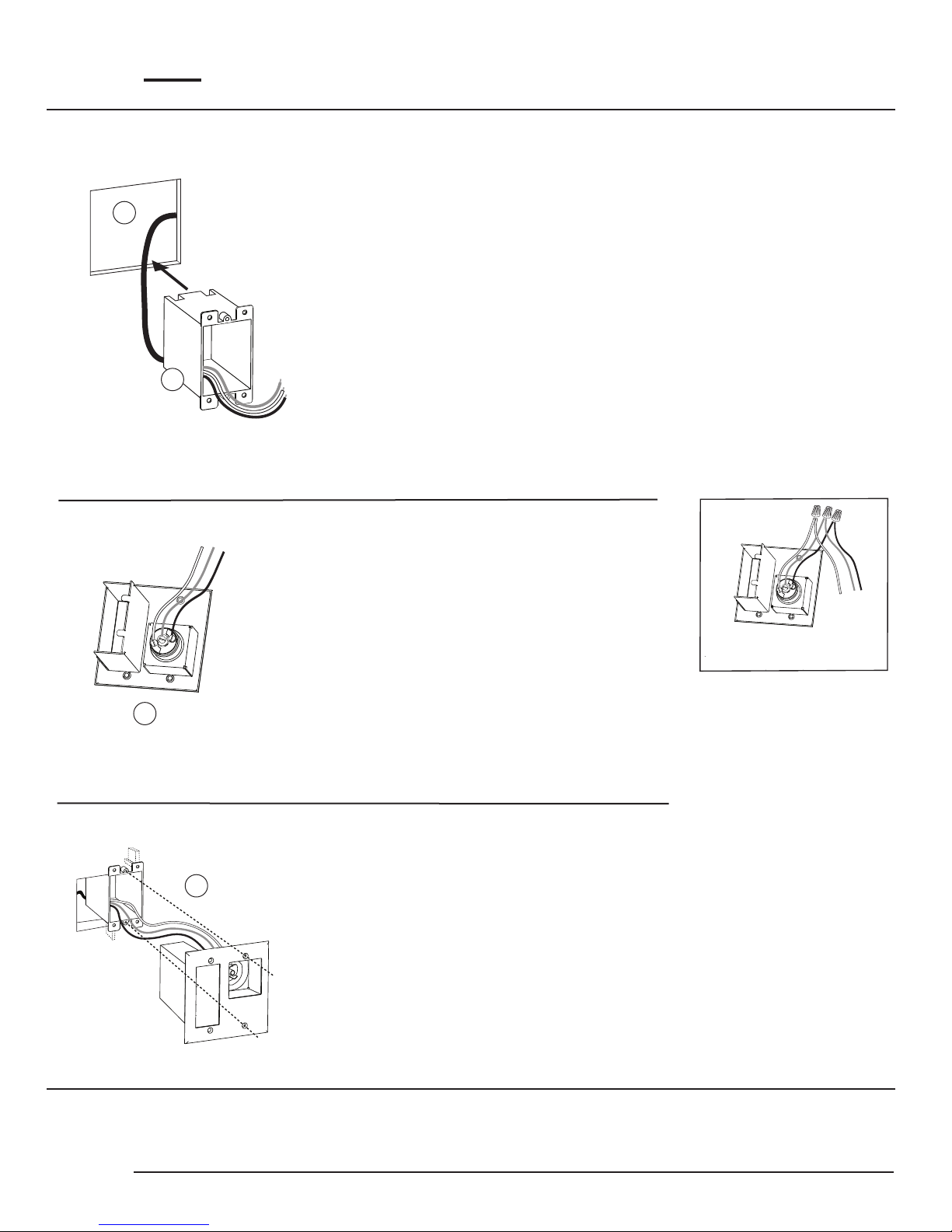
Power Inlet Faceplate Installation Instructions
CAUTION: Not for use in “Fire-Break” walls unless used in conjunction with signal-line modules!
4 in.
1
3
2
3 3/4 in.
STEP 1:
Select a location close to the head-end source equipment. Cut a 4-inch wide by 3 3/4-inch high hole
in the wall. Feed the in wall Romex power cable (not included) through this opening and route them
to the location of the Power Outlet Faceplate.
NOTE: For new construction (pre-wire): Use a Carlon new-work electrical box (Model B122A).
A Carlon low voltage add-on bracket (Model SCIOOSC) may be used with the new-work box to
indicate the location and size of the opening needed in the drywall. The low-voltage bracket
may be left in place when installing the Inlet faceplate.
STEP 2:
Run the AC wires through the lower-left entry of the included outlet box. No more than 1-inch
of wire sheath should extend into the outlet box. 3-inches of wire should be able to extend
beyond the opening of the outlet box. Install the outlet box into the right side of the hole.
STEP 3:
Slide the included shrink-wrap tubing over the ground wire
if it is un-insulated. Strip 3/4-inch of insulation off the AC wires
and attach them to the twist-lock connector screw terminals.
Make sure to attach the wires to the correct terminal:
• Green/Ground wire to Center terminal with Green screw
• White wire to Silver terminal
• Black wire to Copper terminal
NOTE:
To make installation easier, first connect the
included jumpers to the Twistlock Receptacle,
then use the included wire nuts to connect the
jumpers to the building wire. 14 gauge wire is
flexible enough to omit the jumpers. Just strip
1/4” of insulation off the AC wires and attach to
the screw terminals as labeled on the receptacle.
NOTE: Only for use with 15 Amp branch
circuits utilizing 14 or 12 gauge wire.
NOTE: Wire nuts are not recommended for
high-current applications such as powered
subwoofers.
4
STEP 4:
Neatly fold the AC wires as you install the inlet faceplate into
the wall with the AC side fitting into the outlet box. Secure the
unit to the outlet box with the included screws.
NOTE: Only the right side screws are used to mount the inlet faceplate into the included outlet box.
The left side screws are for appearance only and are held on with the included plastic washers.
All four screws are used when mounting the protector to a new-work electrical box and low voltage
add-on bracket.
PAGE 2
 Loading...