

Page 1
PRODUCTS FOR AUDIO, VIDEO AND COMPUTER PROFESSIONALS
Furman Sound, Inc.
1997 South McDowell Blvd.
Petaluma, California 94954-6919 USA
Phone: 707-763-1010
Fax: 707-763-1310
www.furmansound.com
E-mail: info@ furmansound.com
About the PGP-S
The Furman PGP-S Remote Power Switcher is designed for use with Furman's PlugLock-PRO Locking Outlet Systems models PGP-20 and
PGP-60, which are shown on page 2.
The PGP-S is a rugged, 6" x 6" x 4" junction box with three 20-amp relays. It also allows remote control via safe, inexpensive, low-voltage Class
2 wiring. Each of the three circuits is separately controlled by its own REM input terminal.
The PGP-S is designed specifically for mounting on the end of a PGP-20 or PGP-60, and serves as a main junction box for all power
interconnects. It includes an internal 12 VDC supply, and can be controlled from remote locations using the PowerLink, ASD-120, or, for simpler
jobs, the Furman RS-1 and RS-2 Remote System Control panels. The RS-1 provides a maintained key switch; the RS-2 has a momentary switch in
addition to a key for security. (Please see the Furman data sheet "Remote Control Products" or visit the Furman web site for more detailed
information.)
Multiple PGP-S's may be controlled by a single switch closure, or by the PowerLink's or ASD- 1 20's control signals.
Momentary vs. Maintained Contact Switching
An on-off switch of either kind may be used to actuate the three 20-amp circuits available on the PGP-S. Maintained switches, such as most
toggle switches, push-on/push-off button switches, stay open until thrown, then stay closed until thrown
1-9934
again. Power will be available at the PGP-S circuits when the switch is open, and will be removed when it is closed.
Maintained switches are most convenient when there is only one remote switch location; momentary switches allow turn-on or turn-off from
multiple locations. Momentary switches, usually pushbutton types, are normally open and stay closed only as long as the button is pressed.
The PGP-S is factory-configured for maintained operation. Its three 20-amp circuits may be easily converted to momentary operation by moving
jumpers on the internal circuit board. To do this, first disconnect the unit from AC power. Remove the two screws that secure the cover. On the
circuit board, there are six pairs of terminals, three labeled "MAINTAINED" and the other three "MOMENTARY." There are small black jumpers
linking the MAINTAINED terminals. Slide them up and off, and replace them securely over the MOMENTARY terminals. Reattach the cover.
Maintained Mode
In the simplest configuration, to control all PGP-S circuits from a single remote location, connect a maintained-action SPST switch
to the REM 1, 2, 3 and +12V terminals. The Furman RS-1 Remote System Control Panel is an attractively finished key switch
designed for use in single-gang wall mount boxes. From one location, it can control most Furman power products that have
RS- 1 remote capability. If the cable run is greater than
150 feet, we recommend that the REM wire be tied to ground
during ON operation rather than leaving it floating, using a SPDT
switch. (The RS-1 provides for the use of a ground wire, if
desired.)
Momentary Mode
In Momentary Mode, the PGP-S has "memory."
It needs only a momentary signal on the remote
terminal to change its state from OFF to ON, or ON
to OFF.
Page 2
When first plugged in (or after power is lost and
reapplied for any reason) the memory state is OFF,
meaning that no power will be available at the out
RS-2 let. It will stay OFF until turned ON by a
momentary connection of the REM terminal to +1 2V.
It will then stay ON until turned OFF by a second momentary
connection. The ON or OFF action starts immediately when the
momentary switch is closed.
As in Maintained Mode, the three circuits are independent, but can all be controlled by a single switch. The Furman RS-2 Remote System
Control Panel is identical to the RS-1 in most respects, but with a momentary function rather than maintained.
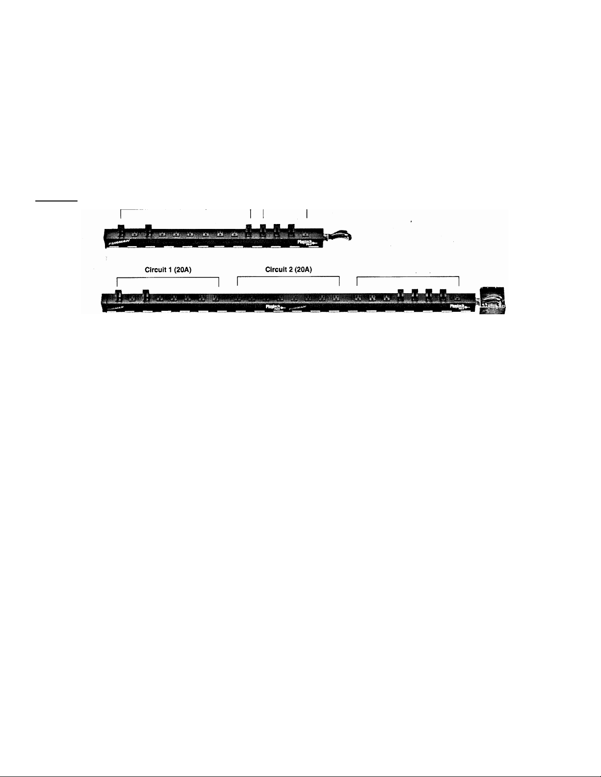
PGP-20 and PGP-60
Circuit I (20A)
Circuit 2 (20A)
Circuit 3 (20A)
PGP-20 (top) and PGP-60 (below)
NOTE: Additional PlugLock brackets and thumbscrews to securely lock plugs and wall warts are available in packages containing six of each. Order Furman
BR-6.
It is ideal for installations requiring multiple remote switches. Just tie REM 1, 2, 3 together. The Status 1, 2, 3 terminals should NOT be tiled together;
each should run to a separate LED. If all REM inputs are tied together, the Status 1 out will usually match Status 2 and 3 accurately, but please read
the important note below.
IMPORTANT NOTE REGARDING MOMENTARY MODE
If multiple PGP-S circuits are being controlled in Momentary Mode, power loss to any one of the units will likely cause its memory to be different than that
of the other units. Not only will this be irritating, it can also be dangerous, as it may be ON when the others are OFF. To correct this potential problem (as
exists in any simple momentary switch product), our thoughtful engineers devised a simple method of holding the switch down (REM to +12) for at least four
seconds. This resets all units to the OFF condition, and avoids having to disconnect AC power from all units.
ILinking Multiple Units
I The three circuits in the PGP-S, or multiple PGP-S units, may be Connected together so that all are controlled by a single switch Closure. All units
must be set to the same mode depending on the type of switch or switches to be used (use momentary mode and momentary switches if more than
one switch is required.) All units must be paralleled by tying together all the +12V terminals, all the HEM terminals, and all the GND terminals (see
Wiring Details). If multiple PGP-S's are linked, they will all turn on simultaneously.
Optional Remote LED Indicator
The PGP-S terminals labeled STATUS are outputs that may be lised to illuminate an LED at a remote location to indicate that power Is available
from the PGP-S. If it is HIGH (+12V relative to the GND germinal), the circuit is ON; if LOW, the circuit is OFF. Simply connect the indicator LED
between STATUS and GND (do not use a rseries resistor). A separate LED must be used to indicate the status of each circuit. Do not connect the
STATUS terminals of multiple units together.
Installation
All four sides of the PGP-S enclosure have multiple knockouts to accommodate every installation. The PGP-S is designed for permanent
installation with 3/4" up to 1.5" conduit. According to the National Electrical Code, 3/4" conduit can accommodate up to five 20 amp circuits using ten
THWN 12 gauge stranded wires; howVver, local codes should be checked for exact requirements. Use of el licensed electrical contractor is
recommended for the best and safest installation. UL and CUL (Canadian) listings are pending.
Dimensions
Dimensions are: 6" H x 6" W x 4" D. The baseplate is 6" square.
Connectors
Page 3

The PGP-S has no connectors. It is designed for use with the Furman PGP-20, PGP-60, or customer-supplied outlets. The end user must
provide fixed input wiring, or power cord(s).
Wiring Details
Inside the PGP-S you will find a circuit board mounted to the underside of the faceplate, and 8 wires:
1 - Green Safety Ground
1 - White Neutral Lead
6 - Black wires, arranged as three pairs.
One black wire of each pair is marked "I". These are the inputs of Relay 1, 2, 3. The other black wire is marked "0". These are the outputs of
Relay 1, 2, 3.
Each black wire marked "I" should be supplied from a separate 20-amp circuit. Each of the black wires marked "0" provides switched AC for the
outlets on the PGP-20 or PGP-60.
The white wire on the PGP-S can connect to the neutral of any one of the three incoming circuits.
The green wire MUST be connected to a safety ground.
NOTE: The PGP-20 has two separate grounds; the PGP-60 has three, and these grounds are isolated from each other If separate grounds are
provided for each available ground on the PGP-20 or PGP-60, the ground of the PGP-S can be connected any one of them.
Three Year Limited Warranty
The Furman PGP-S, PGP-20 and PGP-60 are warranted against failures due to defective parts or faulty workmanship for a period of three years after delivery to the original owner.
During this period, Furman will make any necessary repairs without charge for parts or labor. Shipping charges to the factory or repair station must be prepaid by the owner; return
shipping charges (via UPS Ground) will be paid by Furman. This warranty applies only to the original owner and is not transferable. Also, it does not apply to repairs done other than by
the Furman factory or its Authorized Repair Stations.
This warranty may be cancelled by Furman at its sole discretion if the unit has been subjected to physical abuse or has been modified in any way without written authorization from
Furman. Furman's liability under this warranty is limited to repair or replacement of the defective unit.
Furman will not be responsible for incidental or consequential damages resulting from the use or misuse of its products. Some states do not allow the exclusion of incidental or
consequential damages, so the above limitations may not apply to you. This warranty gives you specific legal rights, and you may also have other rights which vary from state to state.
Service
Before returning any equipment for repair, please be sure that it is adequately packed and cushioned against damage in shipment, and that it is insured. We suggest that you save
the original packaging and use it to ship the product for servicing. Also, please enclose a note giving your name, address, phone number and a description of the problem.
NOTE: All equipment being returned for repair must have a Return Authorization (RA) Number. To get an RA Number, please call the Furman Service Department (707-763-1010 ext.
40) between 8 a.m. and 5 p.m. U.S. Pacific Time.
Please display your RA Number prominently on the front of all packages.
 Loading...