

Furman Merit M-8S Owner's Manual
M-8S - MERIT SERIES PowER CondITIonER • EnGLISH
1
M-8S OWNER’S MANUAL

M-8S - MERIT SERIES PowER CondITIonER • EnGLISH
2
INTRODUCTION
Thank you and congratulations on your purchase
of your Merit M-8S Surge Protector and Power
Sequencer. The M-8S represents an excellent combination of value and performance and has been
designed to provide many years of reliable service.
Please take a moment to read this manual and learn
about the many features and benefits that the Merit
M-8S has to offer.
SAFETY INFORMATION
1. Please read and follow all instructions.
2. Please keep these instructions.
3. Please heed all warnings.
4.
WARNING: This device is intended for indoor
use only. Do not use this device in or near water.
To reduce the risk of fire or electric shock, do not
expose this device to rain or moisture.
5.
CAUTION: To reduce risk of shock, please dis-
connect the M-8S from AC power before servicing
any equipment connected to the M-8S.
6. Clean only with dry cloth.
7.
CAUTION: Do not install near heat sources such
as radiators, heat registers, stoves, or other equipment that may produce intense heat.
8. Protect power cords from being walked on or
pinched, particularly at the point where they exit the
device.
9. Please, only use accessories specified by the
manufacturer.
10. Refer all servicing to qualified personnel. Servicing is required when the unit has been damaged in
any way or fails to operate.
11.
WARNING: Do not use power cord as the main
power disconnect. The device is intended for AC
power sequencing.
12. Do not defeat the safety purpose of the grounded plug. A grounded plug has two blades and a
round grounding contact. If the grounding contact
does not fit into your outlet, please consult an electrician for assistance.
13.
WARNING: This device must be connected to
an AC outlet with a protective earth ground connection.
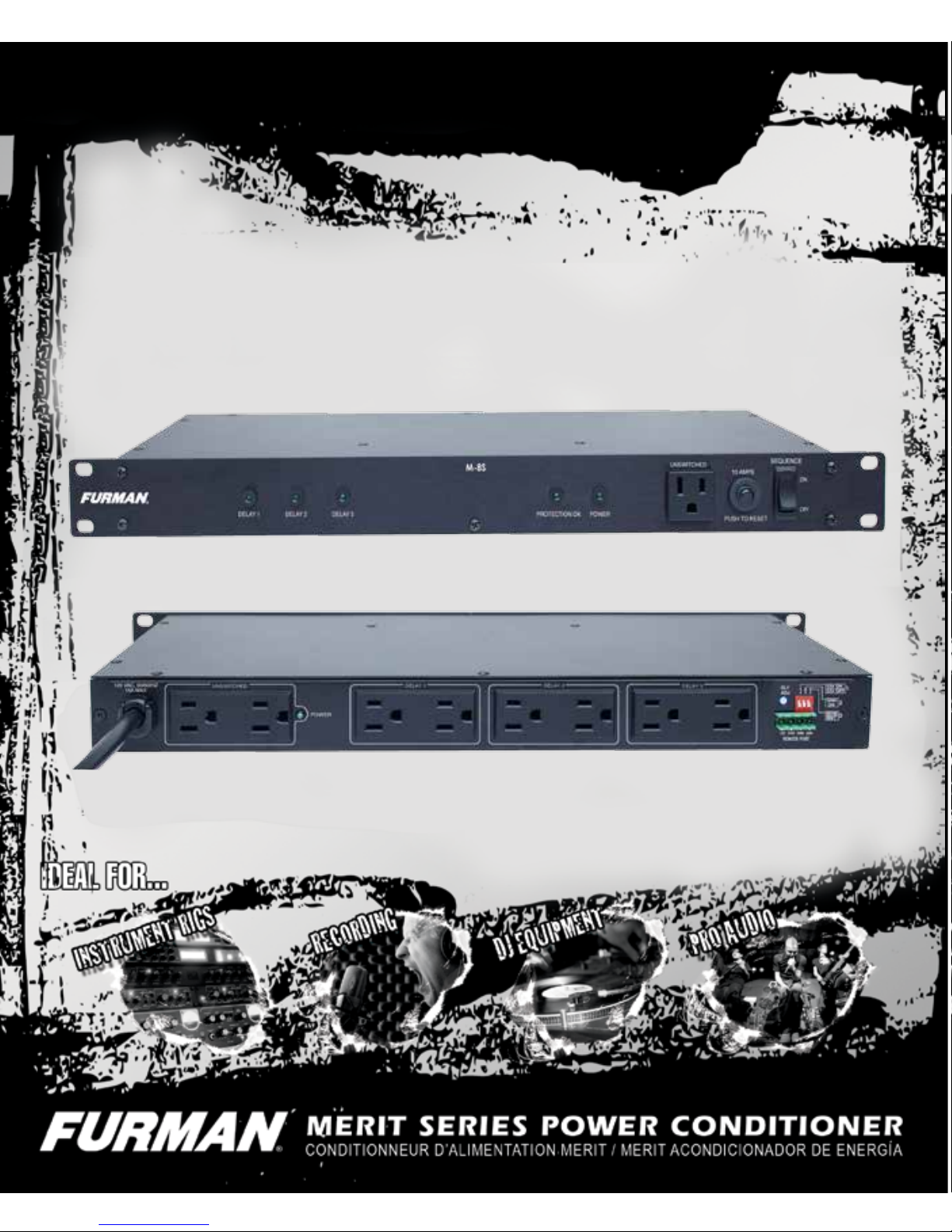
FEATURES
Sequenced Outlets allows large A/V systems to be
safely power cycled on and off with a single switch.
Merit Class Surge Protection Provides basic Line
to Neutral Surge protection with zero ground leakage.
RFI/EMI filtration – Pi type LCR filter gives greater
than 26dB of attenuation from 100 KHz to 1 MHz
Remote Interface Legacy style interface with Phoenix style connector allows remote operation and
compatibility with Furman legacy equipment.
Thermal Circuit Breaker – Rated 15Amps at
120VAC
Green LED – Indicators for status.
9 Outlets – NEMA 5-15R
10 ft. Power Cord – NEMA 5-15P
3 Year Limited Product Warranty – See warranty
documentation at the end of this manual or online at
www.furmansound.com

M-8S - MERIT SERIES PowER CondITIonER • EnGLISH
3
FEATURES (Continued)
Sequenced Outlets
Most sound reinforcement professionals realize the
majority of equipment damage occurs while devices
are either powered up or powered down. Power
sequencing allows A/V equipment to be powered
up in stages which gives equipment time to stabilize before the next stage of equipment is energized. When powering down, the sequence order
is reversed, which results in a soft landing for your
expensive AV equipment.
Although there are many benefits to power sequenc-
ing, perhaps the most well-known is the elimination
of “Speaker Pop”. Speaker Pop is the loud popping
noise that occurs when AV components are powered up simultaneously or out of sequence. Most
people have experienced Speaker Pop. In addition
to being extremely unsettling, Speaker Pop can
stress or damage sound system components such
as amplifiers and speakers. By delaying the activation of the amplifiers until the low level equipment
has had the opportunity to stabilize, Speaker Pop is
virtually eliminated.
Power Sequencing is also useful in preventing nuisance breaker trips. Amplifiers can have very high
in-rush currents at power up. If multiple amplifiers
are activated simultaneously, the in-rush currents
sum together and can exceed the capacity of the
branch circuit which can cause the circuit breaker
to trip. The Furman M-8S prevents breaker trips by
sequencing (offsetting) power activations over time.
This offset sequence allows transient load currents
to occur over several seconds rather than all at
once, which prevents nuisance breaker trips.
The turn-on delay intervals are factory preset to 5
seconds per stage. This delay can be increased or
decreased using the rear panel trim pot adjustment
(see “Adjusting the Delay Interval” for details).
In the event of a power outage, all equipment
plugged into an M-8S will lose power simultaneously.
When power is restored, the behavior of the M-8S
will depend upon switch settings and how the unit
has been configured:
• If the M-8S has been configured for Maintained
mode and the Sequence switch is in the ON position, the delayed outlet groups will turn on in the
normal delayed sequence order when power is
restored.
• If the M-8S has been configured for Momentary
mode the delay outlets will remain off until activated
by the end user.
Merit Class Surge Protection
The M-8S features Furman’s Merit Line to Neutral
Surge protection and RFI/EMI filtration. The Merit
filter is designed to dissipate voltage transients and
protect your equipment from surge events. The
M-8S is also equipped with a Protection OK LED
which provides a visual indication that the M-8S’
surge protection circuit is operational.
Thermal Circuit Breaker
Resettable 15 Amp circut breaker.
Sequence On/Off Switch:
The front panel sequence on/off switch sequentially
powers on and off the DELAY 1, 2, and 3 outlets.
The front and rear panel UNSWITCHED outlets are
always on when power is applied to the M-8S.
M-8S - MERIT SERIES PowER CondITIonER • EnGLISH
4
DELAY 1, 2, and 3 Indicators:
The DELAY 1, 2 and 3 indicators always show the
present state of the corresponding DELAY 1, 2 and
3 outlets. In all cases, if the indicator is ON, the outlet is ON. If the indicator is OFF, the outlet is OFF.
Protection OK Indicator:
Although the Furman Merit Filter assures protection
from transient voltage spikes and surges, nature
can occasionally produce electrical forces that are
beyond the capabilities of any surge suppression
device to absorb without sustaining some degree of
damage. In the rare instance in which damage occurs, the green “PROTECTION OK” LED indicator
located on your front panel will either dim or extinguish completely. If this happens the M-8S’ surge
protection has been compromised and the unit must
be returned to Furman Sound. Please contact Furman Tech Support or your Furman Dealer.
Power Indicator:
The POWER indicator is illuminated any time power
is applied to the M-8S.
Thermal Circuit Breaker
Resettable 15 Amp circut breaker. If this breaker
“trips” please reduce the load.
Sequence On/Off Switch:
The front panel on/off switch sequentially powers on
and off the DELAY 1, 2 and 3 outlets. The front and
rear panel UNSWITCHED outlets are always on.
This on/off switch will operate in either MAINTAINED
or MOMENTARY mode.
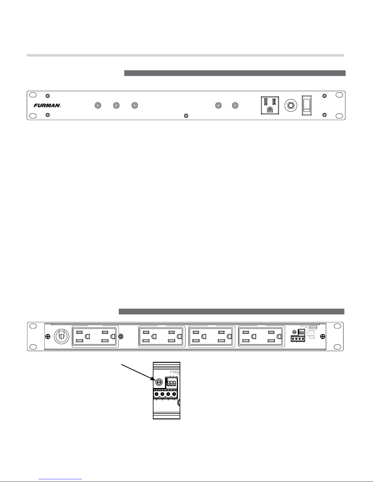
UNSWITCHED
15 AMPS
PUSH TO RESET
PROTECTION OK POWERDELAY 1 DELAY 2 DELAY 3
SEQUENCE
ON
OFF
M-8S
FRONT PANEL FEATURES
UNSWITCHED
DELAY 3
120 VAC, 50/60/HZ
15A MAX
DELAY 2
DELAY 1
12V ON
12V OFF
GND
ON
MOM
MNT
DLY
ADJ
1 2 3
1
2
3
REMOTE PORT
12V STAT REM GND
POWER
REAR PANEL FEATURES
Adjusting the Delay Interval
The delay interval, which is the time
between the turn-on / turn-off of consecutive DELAY outlets 1 and 2, or 2
and 3, is factory preset to approximately
5 seconds. It is possible to lengthen or
shorten the delay interval by changing
the position of the DLY-ADJ trim pot
located on the right side of rear panel.
The delay adjustment procedure is simple and re-
quires a small standard screwdriver. The DLY ADJ
(delay adjustment) is a trim pot that is located on the
rear of the M-8S above the legacy interface and to
the left of the DIP Switches. Locate the rectangular
slot in the center of the trim pot and use a screwdriver to rotate the trim pot to set your desired delay.
The minimum delay (1/2 Second) is achieved when
the trim pot is adjusted fully counter-clockwise. The
maximum delay between stages (~10 Seconds) is
achieved when the pot is rotated fully clockwise.
12V ON
12V OFF
GND
ON
MOM
MNT
DLY
ADJ
1 2 3
1
2
3
REMOTE PORT
12V STAT REM GND
M-8S - MERIT SERIES PowER CondITIonER • EnGLISH
5
Remote Interface
The M-8S has a remote interface which can be used
to control the M-8S remotely using a Furman RS-1
(Maintained) or RS-2 (Momentary) wall switches. In
the most basic, single unit configuration, only two
wires and a switch are required to initiate a remote
ON or OFF sequence. The switch may be either a
momentary or maintained-contact type. If a third &
fourth wire are available, an LED “Status Light” can
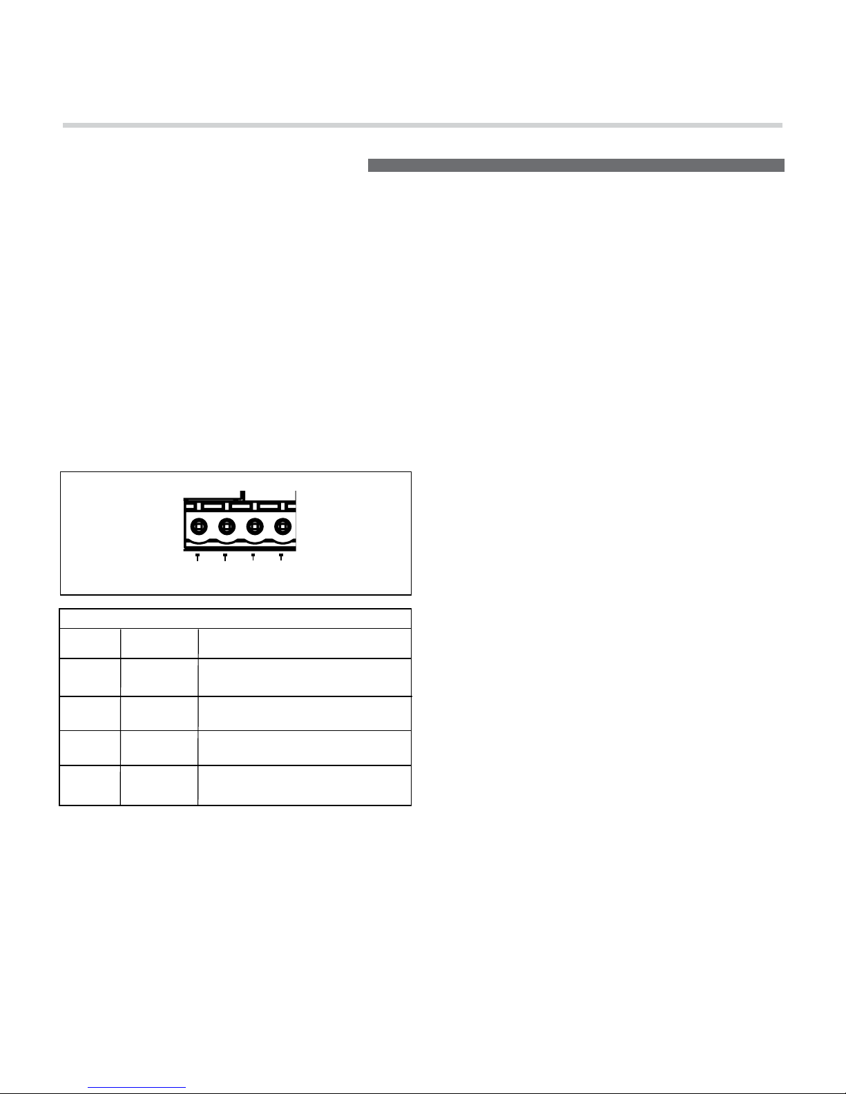
be installed at the remote switching location to indicate the status of the M-8S. The pins on the remote
interface are described below:
PIN 2 STATUS (Output)
The STAT (status) terminal is an output that may be
used to activate an LED to indicate the status of the
M-8S. If the STAT terminal is high, the M-8S Delay
outlets are either ON, or are in the process of sequencing ON. If the STAT terminal is low, the M-8S
Delay outlets are OFF. To use the STAT terminal output simply connect an LED between the STAT and
GND with the Cathode (flat) side of the LED oriented
toward the GND pin (Pin #4). Do not use a series current limiting resistor. If the LED does not light when
the remote switch is ON, check the polarity of the
LED and reverse the leads if necessary.
• If the LED is OFF, the DELAY outputs are OFF
• If the LED is ON, the DELAY outputs are ON
• If the LED is blinking, the DELAY 1, 2 or 3 outputs
are in transition either from ON to OFF or
OFF to ON
PIN 3 REMOTE (Input)
The REM (remote) terminal is provided to allow remotely connected devices to sequence the M-8S ON
or OFF. The M-8S’ REM terminal has been designed
to work with voltages from 5 to 30VDC. Filtering has
been added to this input to prevent false-triggering.
The behavior of the M-8S is controlled by the combination of the signal presented at the REM terminal
input, and the arrangement of the rear panel DIP
switches. Please refer to REAR PANEL DIP SWITCH
section (page 6) for more details.
PIN 4 GND (Power)
The GND (ground) terminal pin serves a ground reference point for all other pins on the Remote Interface. GND can also be fed back into the REM pin
(Pin #3) to activate the sequence when the M-8S has
been configured for GND ON mode. Please note that
the GND terminal on the Remote Interface is not the
same as chassis ground and should never be connected to chassis ground.
REMOTE PORT
12V STAT REM GND
12V ON
12V OFF
GND
ON
MOM
MNT
1 2 3
12V 0.5A
3
2
Remote Interface
Pin Label Description
1 12V 12VDC @12mA General
Purpose Output
2 STAT Output for driving an external
status LED
3 REM Input for controlling the
sequencer remotely
4 GND Ground (12VDC Power
Common)
Remote Interface
PIN 1 +12VDC (12VDC Voltage Source)
The +12VDC terminal pin is a general purpose,
12VDC voltage source relative to the GND (#4) pin. It
is provided to allow the user to control the operation
of the sequencer by feeding the +12VDC signal back
into the REM terminal input; which is pin #3 on the
same barrier strip.
1 2 3 4
REAR PANEL FEATURES (continued)

M-8S - MERIT SERIES PowER CondITIonER • EnGLISH
6
DIP 1
12V ON
OFF
ON
OFF
ON
OFF
ON
OFF
ON
DIP 2
GND ON
OFF
OFF
ON
ON
OFF
OFF
ON
ON
DIP 3
MOM/MNT
OFF
OFF
OFF
OFF
ON
ON
ON
ON
MODE
+12V OFF
+12V ON
GND ON
GND ON
Momentary
Momentary
Momentary
Momentary
Note: The front panel SEQUENCE ON/OFF switch acts as an override. The SEQUENCE switch must be
in the ON position for any of the sequenced outlets to be activated.
Sequences the M-8S ON when REM = Open Circuit
Sequences the M-8S OFF when REM = 12VDC
Sequences the M-8S ON when REM = 12VDC
Sequences the M-8S OFF when REM = Open Circuit
Sequences the M-8S ON when REM is connected to GND terminal
Sequences the M-8S OFF when REM = Open Circuit
Sequences the M-8S from ON to OFF or OFF to ON each time +12V is applied to the REM input.
1 2 3
FACTORY DEFAULT SETTING
Rear Panel DIP Switch
A rear panel three position DIP switch is used to set
the sequence mode (+12V ON, +12V OFF, GND ON,
Mom/ Maint) which defines how the M-8S will react
to the signal presented on its REM input. The table
below summarizes the behavior which is described
in further detail below. Note that DIP switch position 2 overrides the setting of DIP switch 1, and DIP
switch 3 overrides switches 1 and 2.
DIP Switch position #1 (Factory default is OFF)
DIP Switch position 1 defines how the M-8S will
behave when +12VDC is applied to the REM pin
on the Remote interface. If this switch is in the ON
position, the M-8S will sequence ON when +12V
is applied to the REM input. If this switch is in the
OFF position (+12V OFF) the M-8S will sequence
OFF when +12V is applied to the REM input. DIP
switches 2 and 3 must be in the OFF position (Main-
tained mode).
DIP Switch position #2 (Factory default is OFF)
DIP Switch position 2 defines how the M-8S will
behave when GND is applied to the REM pin on the
Remote interface. If this switch is in the ON position,
the M-8S will sequence ON when GND is applied to
the REM input. If this switch is in the OFF position
the M-8S will follow the behavior defined by DIP
Switch #1. DIP switch 3 must be in the OFF position
(Maintained mode).
DIP Switch position #3 (Factory default is OFF)
DIP Switch position 3 defines the switching preference for switches or devices connected to the REM
pin on the Remote Interface. If this switch is in the
ON position, the M-8S will operate in Momentary
mode. If this switch is in the OFF position the product will operate in Maintained mode.
Maintained switches, for example toggle switches
or push-ON / push-OFF push button latching
switches maintain their contact position until the
switch is actuated a second time. Thus a switch that
is closed will remain closed until the switch position
is changed (such as the Furman RS-1).
REAR PANEL FEATURES (continued)
12V ON
12V OFF
GND
ON
MOM
MNT
DLY
ADJ
1 2 3
1
2
3

M-8S - MERIT SERIES PowER CondITIonER • EnGLISH
7
Momentary switches, for example non-latching
push buttons, are momentary contact devices that
maintain their contact position (open or closed) only
as long as the switch is held in a given position.
When the switch actuator is released, the switch
reverts to its normal position (such as the Fuman
RS-2).
A switch of either kind may be used to actuate the
M-8S’s remote operation. Maintained switches are
generally most convenient when there is only one
remote switch location used to control the M-8S.
When more than one switching location is required,
momentary switches allow the M-8S to be sequenced ON or OFF from multiple locations.
CONNECTING MULTIPLE M-8S UNITS TOGETHER
REAR PANEL FEATURES (continued)
Multiple M-8S units can be linked together (via their
remote interface) to control additional system needs
or requirements. There are two basic connection
methods for the M-8S; Serial and Parallel. The
connection method you use may be series, parallel,
or a combination thereof and will depend upon the
requirements of your specific installation.
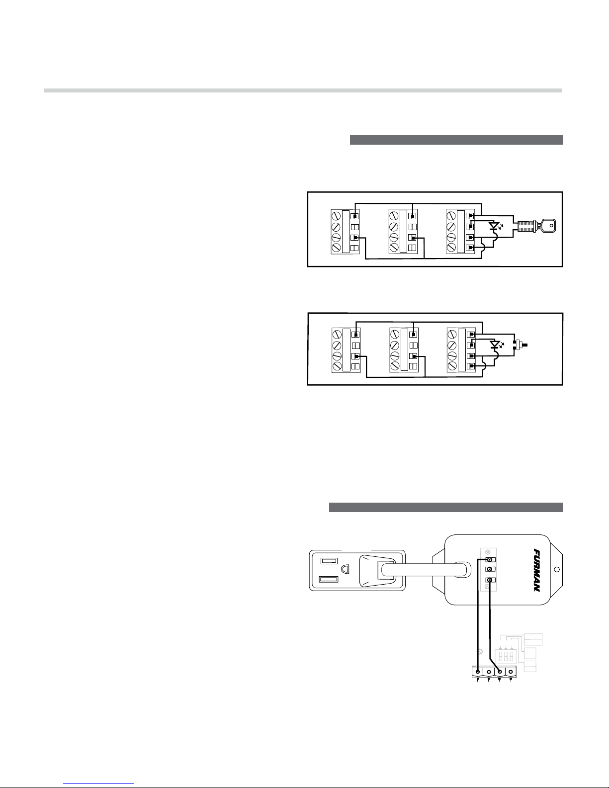
M-8S in Series Mode:
Series mode connection is normally used when
more than three delay stages are needed. Combining M-8S units in series requires an accessory
relay (Furman P/N PS-REL) to trigger secondary
(downstream) units. When connecting M-8S units
in series, the PS-REL is plugged into one of the
DELAY 3 outlets on the primary (upstream) unit and
the relay terminals on the PS-REL are connected to
the remote interface on the secondary (downstream)
unit. When the DELAY 3 outlets on the primary unit
are activated the PS-REL is also activated – which
triggers the sequence to start on the secondary
(downstream) M-8S. Series mode connection can
be repeated for any number of M-8S units. Further
information on the PS-REL can be found on the
Furman website: http://www.furmansound.com/pdf/
manuals/PS-REL_manual.pdf
Power Indicator:
The POWER indicator is illuminated any time power
is applied to the M-8S. This LED indicates the unswitched outlets are powered.
M-8S in Parallel Mode:
Parallel mode can be used to activate loads in
excess of 15 Amps by distributing the loads over
one or more M-8S units. When connected in parallel (see Figures A and B, pg. 8) all connected M-8S
units will activate their Delay 1 simultaneously. The
activation times of Delay stages 2 and 3 will depend
upon the delay setting of each unit. If M-8S units
are operating in parallel to increase load capacity,
each unit should be connected to an independent
15 to 20 Amp branch circuit and breaker. If in doubt,
please consult with a qualified electrician to verify
that your facility can support the load currents
required for your installation.
M-8S - MERIT SERIES PowER CondITIonER • EnGLISH
8
CONNECTING MULTIPLE M-8S UNITS IN PARALLEL
Parallel Maintained Mode:
To control multiple M-8S units with a single remote
switch; connect the REM, +12V, terminals of all units
in parallel (Figure A). Make sure that the DIP #3 is
OFF and the positions of DIP #1 and DIP #2 on all
connected units are set to the same position. Connect a single maintained switch (such as the Furman
RS-1) to the nearest M-8S.
Parallel Momentary Mode:
To control multiple M-8S units with multiple switches,
use Momentary mode (DIP #3 ON) and connect
the REM, and +12V, terminals of all units in parallel (Figure B) and connect one or more momentary
contact switches in parallel with the REM, and +12V
terminals. All connected units will change state
(from ON to OFF, or OFF to ON) each time one of
the switches are pressed.
Helpful Hint: Breaker trips or unauthorized access
to the front panel Sequence switch can cause linked
units operating in Momentary mode to fall out of
sync. To restore sync, press and hold the remote
(Figure B) switch for more than 4 seconds. This will
force all linked units into the OFF state. Linked units
can also be re-synced by cycling AC power to all
connected units.
CONNECTING MULTIPLE M-8S UNITS IN SERIES
Series Maintained Mode:
To operate multiple M-8S units in series using a
single remote switch; connect a maintained contact
switch between the REM and +12V on the primary
unit and connect a PS-REL between the DELAY 3
outlet on the primary unit and the REM and +12V
pins on the secondary unit. Continue connecting
M-8S units in this pattern until all units have been
connected.
When the primary unit sequences ON the PS-REL
will activate as soon as the DELAY 3 outlet on the
primary unit has been activated. This will cause the
secondary unit to begin to sequence on.
DELAY 3
PRIMARY M-8S UNIT
REMOTE PORT
12V STAT REM GND
1 2 3
12V ON
12V OFF
GND
ON
MOM
MNT
1
2
3
DLY
ADJ
AC RELAY ACCESSORY
MODEL PS-REL
C NO NC
SECONDARY M-8S UNIT
DIP 1, 2, 3 = OFF
PS-REL
+12V
STATUS
REM
GND
+12V
STATUS
REM
GND
+12V
STATUS
REM
GND
+12V
STATUS
REM
GND
+12V
STATUS
REM
GND
+12V
STATUS
REM
GND
Fig. A - Three M-8S units configured for Parallel Maintained mode
with LED indicator.
Fig. B - Three M-8S units configured for Parallel Momentary
with LED indicator.
M-8S - MERIT SERIES PowER CondITIonER • EnGLISH
9
Please note the following:
• In series mode, the DELAY 3 outlets of the primary
unit and the DELAY 1 outlets of the secondary unit
will activate simultaneously.
• When sequencing off series connected units, the
secondary units will begin to sequence off as soon
CONNECTING MULTIPLE M-8S UNITS IN SERIES (continued)
as the DELAY 3 outlets on the primary unit turns
off. This means that both the primary and secondary
units will sequence off at the same time. In other
words, sequencing ON and sequencing OFF are not
equivalent. If your installation requires symmetrical
sequencing please consult Furman Technical Support for other product options.
TROUBLESHOOTING
M-8S shows no signs of life – no lights or activity
• Confirm that unit is receiving 120VAC power.
• Confirm that the front panel breaker is not tripped.
M-8S Power lamp is on, but unit does not sequence
• Confirm that the sequence switch is in the ON
position.
• Confirm that the signals present at the remote
interface allow sequencing.
• If in doubt, return the M-8S to factory default
settings and re-test.
M-8S Power lamp is on, but PROTECTION OK
LED is dim or off
• Surge protection circuit has been damaged; return
unit to Furman authorized repair facility for service.
M-8S operates, but trips circuit breaker
• Check loads on all outlets, reduce if necessary.
• Check loads on branch circuit, reduce if necessary.
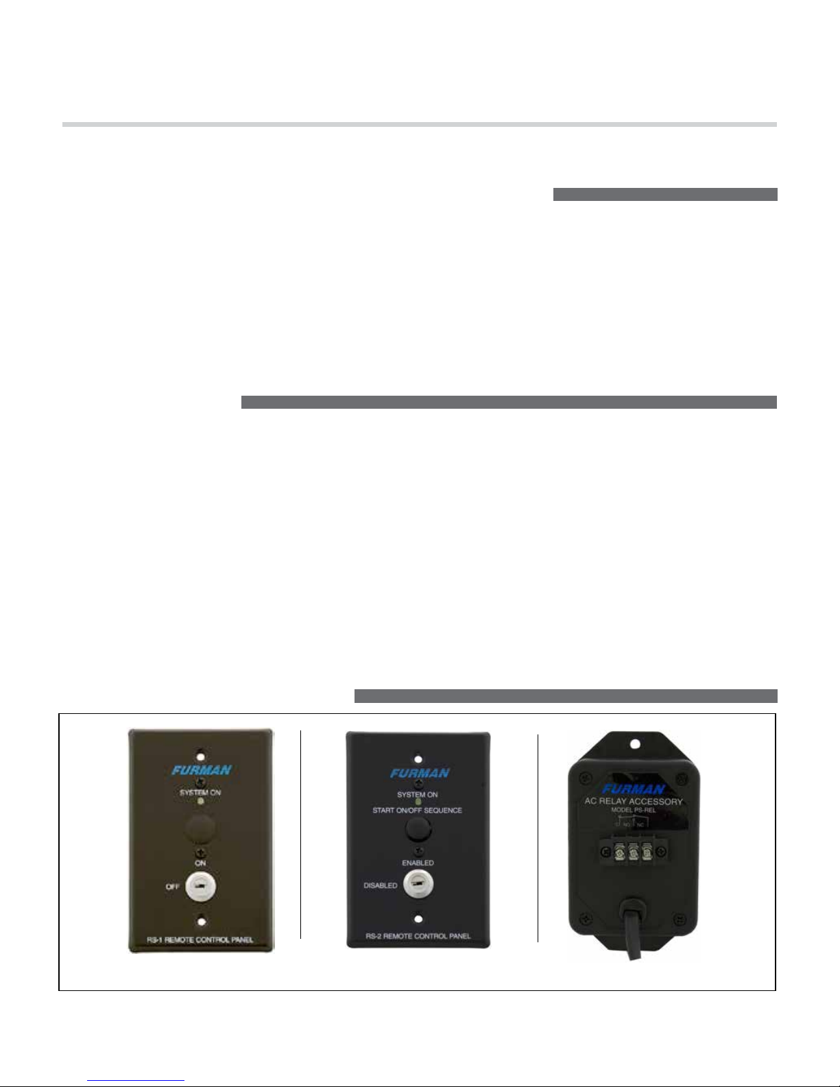
COMPATIBLE FURMAN PRODUCTS
RS-1 – Remote Key Switch RS-2 – Remote Key Switch w/ Push Button PS-REL – Accessory Relay
M-8S - MERIT SERIES PowER CondITIonER • EnGLISH
10
SPECIFICATIONS
Maximum AC Current Rating:
• 15 Amps, 120 VAC (Thermal breaker)
• AC Cord: 14AWGx3, 10 feet, black, fixed,
NEMA 5-15P plug
AC Receptacles:
• Convenience Outlet (Front Panel)
1 Un-switched NEMA 15-5R
• Rear Panel Outlets: 2 Un-switched NEMA 5-15R
(1 duplex),
• 6 Sequenced NEMA 5-15R (3 duplexes, each
controlled by separate relay)
Surge Protection:
• AC Surge Protection: Merit Class (sacrificial)
• Spike Protection Mode: Line to neutral, zero ground
leakage
• Max Continuous Operating Voltage: 130V RMS
• Max Clamp Voltage: 500 Volts Peak
• Peak Impulse Current: 12,000 Amps
• Energy Rating (2 X 820µS): 225 Joules
AC Filtering:
• Pi LCR Filter
• Noise Attenuation: >26dB, 100 Khz to 1 MHz
Operating Temperature Range:
• 5C (40F) to 40C (105F) degrees
Humidity Range:
User Interface:
• Rocker Switch: Front panel, Sequence (ON, OFF)
• Thermal Circuit Breaker: Front panel, push to reset
• Front panel indicators Delay 1, Delay 2, Delay 3,
Power, Protection OK
Control/Status/Triggering (Rear Panel):
• Rear Panel DIP Switches: 12V Mode On/Off,
GND Mode On, Momentary/Maintained
• Potentiometer: Rear panel, time calibration fine tune
delay adjust
• Remote Terminal: +5-30VDC In, 12VDC (12mA) Out
• Remote Terminal: Phoenix type 4-Pin Connector with
Screw terminals; +12V, STAT, REM, GND
(Class 2 Wiring)
Size: 1.75” X 19.00” X 6.5” (HWD) – ANSI 1RU
Mass: 5.3 lbs.
Power Consumption (No Load): • 5 Watts
Safety Agency:
• C/CSA/US
Specifications in this manual are subject to change without notice due to design improvements and upgrades.
THREE YEAR
PRODUCT WARRANTY
Furman warrants to the original purchaser of this product for a
period of three (3) years from the date of purchase, that the unit
shall be free of defects in design, material or workmanship, and
Furman will repair or replace any defective unit. Your receipt is
your proof of purchase.
CAUTION! WARRANTY LIMITATION
FOR INTERNET PURCHASERS
Furman products purchased through the Internet do not carry a valid
Product Warranty unless purchased from an Authorized Furman
Internet Dealer and the original factory serial numbers are intact
(they must not have been removed, defaced or replaced in any way).
Purchasing from an Authorized Furman Internet Dealer insures that
the product was intended for consumer use, has passed all quality
inspections and is safe. Buying through auction sites or unauthor-
ized dealers may result in the purchase of salvaged, failed and/
or products not intended for use in the US. In addition, Authorized
Furman Internet dealers have demonstrated sufficient expertise to
insure warranty compliant installations. For a list of Authorized
Furman Internet Dealers go to www.furmansound.com
C US

M-8S - MERIT SERIES PowER CondITIonER • EnGLISH
11
3 YEAR LIMITED WARRANTY
PLEASE SAVE YOUR SALES RECEIPT! The receipt
is your proof of purchase and confirms the product was
purchased at an authorized Furman dealer. It will need
to be submitted to Furman in order to process any warranty claims.
Furman, a brand of Core Brands LLC., warrants its
M-8S (the “Product”) as follows:
Furman warrants to the original purchaser of the
product that the product sold hereunder will be free
from defects in material and workmanship for a period
of three years from the date of purchase. If the product
does not conform to this Limited Warranty during the
warranty period (as herein above specified), purchaser
shall notify Furman of the claimed defects by calling
800-472-5555 or via email (techsupport@furmansound.
com). If the defects are of such type and nature as to
be covered by this warranty, Furman shall authorize
purchaser to return the product to Furman. Warranty
claims MUST be accompanied by a copy of the original
purchase invoice or receipt showing the purchase
date. Shipping charges to Furman must be prepaid by
the purchaser of the product. Furman shall, at its own
expense, furnish a replacement product or, at Furman’s
option, repair the defective product. Return shipping
charges back to purchaser will be paid by Furman.
THE FOREGOING IS IN LIEU OF ALL OTHER WARRANTIES, EXPRESS OR IMPLIED, INCLUDING BUT
NOT LIMITED TO THE IMPLIED
WARRANTIES OF MERCHANTABILITY AND FITNESS FOR A PARTICULAR PURPOSE.
Furman does not warrant against damages or defects
arising out of improper use or abnormal handling of the
product, or against defects or damages arising from improper installation. This warranty shall be cancelable by
Furman at its sole discretion if the product is modified
in any way without written authorization from Furman
or Core Brands LLC. This warranty also does not apply
to products upon which repairs have been affected or
attempted by persons other than pursuant to written
authorization by Furman or Core Brands LLC.
THIS WARRANTY IS EXCLUSIVE. The sole and
exclusive obligation of Furman shall be to repair or
replace the defective product in the manner and for
the period provided above. Furman shall not have any
other obligation with respect to the products or any part
thereof, whether based on contract, tort, strict liability
or otherwise. Under no circumstances, whether based
on this Limited Warranty or otherwise, shall Furman be
liable for incidental, special, or consequential damages.
This Limited Warranty states the entire obligation of Furman with respect to the product. If any part of this Limited
Warranty is determined to be void or illegal, the remainder
shall remain in full force and effect.
SERVICE
NOTE: All equipment being returned for repair must
have an RMA (Return Materials Authorization) number.
To receive an RMA number, please contact Furman
Technical Services at techsupport@furmansound.com or
call, (800) 472-5555, between the hours of 6 a.m. and 4
p.m., U.S. Pacific Time. In order to issue an RMA number,
Furman will require the Model and Serial Number of the
product, your name, address, phone number, and a brief
description of the problem. An email address, if available,
will be helpful in expediting your RMA. If the unit is being
returned for warranty service, further information may be
required to substantiate the warranty status.
Please be sure that your RMA product it is adequately
packed and cushioned against damage in shipment. We
suggest that you retain and use the original packaging to
ship RMA materials for servicing. Furman assumes no
liability for damages that occur during shipment. The RMA
number should be prominently displayed on the shipping
label or outside of the package. Please enclose a note
with the RMA number, the Serial Number, your name,
address, phone number and a brief description of the
problem – failure to do so may delay diagnosis and repair
Furman Sound and Core Brands LLC. reserve the right to
repackage and return repaired items using packaging materials deemed appropriate and suitable to for safe transit.
Customer supplied materials, such as blankets, bubble
wrap, packaging foam, and the like may be discarded if
not suitable for shipment. Additionally, professional containers such as Road/Flight Cases may be shipped back
separately at the owner’s expense if Furman Technical
Services determines that the Road / Flight Case is unsuitable for the safe return of the RMA Materials.
Units under warranty shall be returned free of charge as
stated in the Limited Warranty section of this manual. If
you have any questions, please contact Furman Technical
Services between 6 a.m. and 4 p.m., U.S. Pacific Time,
(800) 472-5555, or via email techsupport@furmansound.
com
 Loading...