

Page 1

User Manual
funkwerk W500
Copyright © February 2010 Funkwerk Enterprise Communications GmbH
Version 2.1
Page 2

Purpose This document describes the installation and usage of the funkwerk W500.
Liability While every effort has been made to ensure the accuracy of all information in this manual, Funkwerk
Enterprise Communications GmbH cannot assume liability to any party for any loss or damage caused
by errors or omissions or by statements of any kind in this document and is only liable within the scope
of its terms of sale and delivery.
The information in this manual is subject to change without notice. Additional information and changes
can be found at www.funkwerk-ec.com.
Trademarks Product names and trademarks mentioned are usually the property of the respective companies and
manufacturers.
Copyright All rights are reserved. No part of this publication may be reproduced or transmitted in any form or by
any means – graphic, electronic, or mechanical – including photocopying, recording in any medium,
taping, or storage in information retrieval systems, without the prior written permission of Funkwerk
Enterprise Communications GmbH. Adaptation and especially translation of the document is
inadmissible without the prior consent of Funkwerk Enterprise Communications GmbH.
Guidelines and Standards Funkwerk products comply with the following guidelines and standards:
R&TTE Directive 1999/5/EG
CE marking for all EU countries and Switzerland
You will find detailed information in the Declarations of Conformity at www.funkwerk-ec.com.
How to Reach Funkwerk
Enterprise Communications
GmbH
Funkwerk Enterprise Communications GmbH
Suedwestpark 94
D-90449 Nuremberg
Germany
Telephone: +49 180 300 9191 0
Fax: +49 180 300 9193 0
Internet: www.funkwerk-ec.com
Page 3

1 Introduction . . . . . . . . . . . . . . . . . . . . . . . . . . . . . . . . . . . . . . . . . . . . 7
1.1 Technical Features and Advantages . . . . . . . . . . . . . . . . . . . . . . . . . . . . . 7
1.2 System Configurations . . . . . . . . . . . . . . . . . . . . . . . . . . . . . . . . . . . . . . . . 8
2 Hardware Installation . . . . . . . . . . . . . . . . . . . . . . . . . . . . . . . . . . . . 9
2.1 Checking for Completeness . . . . . . . . . . . . . . . . . . . . . . . . . . . . . . . . . . . . 9
2.2 System Requirements . . . . . . . . . . . . . . . . . . . . . . . . . . . . . . . . . . . . . . . . 9
2.3 Mechanical Description . . . . . . . . . . . . . . . . . . . . . . . . . . . . . . . . . . . . . . 10
2.4 Hardware Installation . . . . . . . . . . . . . . . . . . . . . . . . . . . . . . . . . . . . . . . . 12
3 Configuration . . . . . . . . . . . . . . . . . . . . . . . . . . . . . . . . . . . . . . . . . . 15
3.1 Access to the Web-based
Configuration Program . . . . . . . . . . . . . . . . . . . . . . . . . . . . . . . . . . . . . . . 15
3.1.1 Status . . . . . . . . . . . . . . . . . . . . . . . . . . . . . . . . . . . . . . . . . . . . . 17
3.1.2 System . . . . . . . . . . . . . . . . . . . . . . . . . . . . . . . . . . . . . . . . . . . . 18
3.2 Wireless . . . . . . . . . . . . . . . . . . . . . . . . . . . . . . . . . . . . . . . . . . . . . . . . . . 19
3.2.1 WPS Settings . . . . . . . . . . . . . . . . . . . . . . . . . . . . . . . . . . . . . . . 19
3.2.2 Wireless Settings . . . . . . . . . . . . . . . . . . . . . . . . . . . . . . . . . . . . 20
3.2.3 Security . . . . . . . . . . . . . . . . . . . . . . . . . . . . . . . . . . . . . . . . . . . . 28
3.2.4 MAC Address Filter . . . . . . . . . . . . . . . . . . . . . . . . . . . . . . . . . . . 38
3.3 Management . . . . . . . . . . . . . . . . . . . . . . . . . . . . . . . . . . . . . . . . . . . . . . 40
3.3.1 Password . . . . . . . . . . . . . . . . . . . . . . . . . . . . . . . . . . . . . . . . . . 40
3.3.2 Configuration File . . . . . . . . . . . . . . . . . . . . . . . . . . . . . . . . . . . . 41
3.3.3 Upgrade Firmware . . . . . . . . . . . . . . . . . . . . . . . . . . . . . . . . . . . . 42
3.4 Monitoring . . . . . . . . . . . . . . . . . . . . . . . . . . . . . . . . . . . . . . . . . . . . . . . . . 43
3.4.1 Logs . . . . . . . . . . . . . . . . . . . . . . . . . . . . . . . . . . . . . . . . . . . . . . 43
3.4.2 Statistics . . . . . . . . . . . . . . . . . . . . . . . . . . . . . . . . . . . . . . . . . . . 44
3.4.3 List of Associated Devices . . . . . . . . . . . . . . . . . . . . . . . . . . . . . 45
User Manual User Manual
3
Page 4

4 Use of the Device in Various Network Scenarios . . . . . . . . . . . . .47
4.1 Bridge Mode with WEP . . . . . . . . . . . . . . . . . . . . . . . . . . . . . . . . . . . . . . .47
4.1.1 Login . . . . . . . . . . . . . . . . . . . . . . . . . . . . . . . . . . . . . . . . . . . . . . .47
4.1.2 Navigation Menu . . . . . . . . . . . . . . . . . . . . . . . . . . . . . . . . . . . . . .48
4.1.3 Setting Operation Mode . . . . . . . . . . . . . . . . . . . . . . . . . . . . . . . .49
4.1.4 Advanced Settings / Setting MAC Address . . . . . . . . . . . . . . . . .50
4.1.5 Checking Status . . . . . . . . . . . . . . . . . . . . . . . . . . . . . . . . . . . . . .52
4.2 Access Point Mode with WPA2-PSK and MAC Filter . . . . . . . . . . . . . . . .53
4.2.1 Login . . . . . . . . . . . . . . . . . . . . . . . . . . . . . . . . . . . . . . . . . . . . . . .54
4.2.2 Navigation Menu . . . . . . . . . . . . . . . . . . . . . . . . . . . . . . . . . . . . . .55
4.2.3 Setting Operation Mode . . . . . . . . . . . . . . . . . . . . . . . . . . . . . . . .56
4.2.4 Setting the Security Mode . . . . . . . . . . . . . . . . . . . . . . . . . . . . . .58
4.2.5 Checking Status . . . . . . . . . . . . . . . . . . . . . . . . . . . . . . . . . . . . . .61
4.3 AP + Repeater Mode with WPA2-PSK . . . . . . . . . . . . . . . . . . . . . . . . . . .62
4.3.1 Login . . . . . . . . . . . . . . . . . . . . . . . . . . . . . . . . . . . . . . . . . . . . . . .63
4.3.2 Navigation Menu . . . . . . . . . . . . . . . . . . . . . . . . . . . . . . . . . . . . . .64
4.3.3 Setting Operation Mode . . . . . . . . . . . . . . . . . . . . . . . . . . . . . . . .65
4.3.4 Setting the Security Mode . . . . . . . . . . . . . . . . . . . . . . . . . . . . . .67
4.4 Wireless Client Mode with WPA2-PSK . . . . . . . . . . . . . . . . . . . . . . . . . . .67
4.4.1 Login . . . . . . . . . . . . . . . . . . . . . . . . . . . . . . . . . . . . . . . . . . . . . . .68
4.4.2 Navigation Menu . . . . . . . . . . . . . . . . . . . . . . . . . . . . . . . . . . . . . .68
4.4.3 Setting Operation Mode . . . . . . . . . . . . . . . . . . . . . . . . . . . . . . . .69
4.4.4 Wireless Client . . . . . . . . . . . . . . . . . . . . . . . . . . . . . . . . . . . . . . .71
4.4.5 Security Mode for the Wireless Client . . . . . . . . . . . . . . . . . . . . . .74
4.4.6 Checking the Client’s Status . . . . . . . . . . . . . . . . . . . . . . . . . . . . .75
5 Warranty . . . . . . . . . . . . . . . . . . . . . . . . . . . . . . . . . . . . . . . . . . . . . .77
5.1 Replacement, Repair and Refund for Hardware . . . . . . . . . . . . . . . . . . . .78
5.2 Technical Data . . . . . . . . . . . . . . . . . . . . . . . . . . . . . . . . . . . . . . . . . . . . . .80
4
User Manual User Manual
Page 5

6 Safety Precautions . . . . . . . . . . . . . . . . . . . . . . . . . . . . . . . . . . . . . 81
6.1 General Safety Precautions in English . . . . . . . . . . . . . . . . . . . . . . . . . . . 82
6.2 Allgemeine Sicherheitshinweise in Deutsch . . . . . . . . . . . . . . . . . . . . . . . 85
6.3 Indicaciones generales de seguridad en español . . . . . . . . . . . . . . . . . . 89
6.4 Consignes générales de sécurité en français . . . . . . . . . . . . . . . . . . . . . 93
6.5 Indicazioni generali di sicurezza in italiano . . . . . . . . . . . . . . . . . . . . . . . 96
6.6 Ogólne instrukcje bezpieczeñstwa w jêzyku polskim . . . . . . . . . . . . . . . . 99
6.7 Considerações genéricas em matéria de segurança,
em português . . . . . . . . . . . . . . . . . . . . . . . . . . . . . . . . . . . . . . . . . . . . . 103
User Manual User Manual
5
Page 6

6
User Manual User Manual
Page 7

Introduction
1Introduction
This product was specially designed to satisfy the needs of small offices
or home offices.
It represents a complete solution for wireless networking and is very easy to
configure and operate without any special prior technical knowledge. This Man
ual contains instructions for installing and configuring W500. Please read this
Manual thoroughly before you install and use this product. This way you will be
able to derive the maximum benefit from the functionality of the device.
1.1 Technical Features and Advantages
1
-
■ Interoperable with IEEE 802.11g wireless devices
■ Support for AP, wireless client, repeater and bridge modes
■ High security: WEP encryption (64, 128 and 152 bit), 802.1x (EAP-TLS,
EAP-TTLS, LEAP, EAP-PEAP), WPA/WPA-PSK, WPA2/WPA2-PSK, wire
less MAC filter list
■ Direct interface to IEEE 802.3 Fast Ethernet networks (10/100-BaseTX RJ-
45 LAN port)
■ Supports data rates of 1, 2, 5.5, 11, 6, 9, 12, 18, 24, 36, 48, 54 Mbps
■ Wi-Fi Protected Setup (WPS) allows users to automatically establish a con-
nection between W500 and WPS-capable wireless clients. Users can configure the wireless client for the connection with W500 at the press of a button.
-
User Manual
7
Page 8

1
Introduction
1.2 System Configurations
W500 can be set up for a wealth of network systems configurations.
Wireless Infrastructure In a wireless infrastructure, W500 acts as an access point (AP) with repeater.
The access point links wireless clients with one another. Here the AP is at the
center of all wireless communication. This makes communication more effi
cient, because the wireless adapters do not have to be within direct range of
each other.
-
Wireless Infrastructure
with Stations in the
Wired LAN
W500 allows access to your wired LAN. A LAN with integrated wired and wire-
less components is known as infrastructure configuration. A group of WLAN-PC
users and an access point form a basic service set (BSS). Each wireless con
nected PC in this BSS can make contact with every computer in your wired network via the access point.
-
8
User Manual
Page 9

Hardware Installation
2 Hardware Installation
This chapter describes the initial setup of the access point (AP).
2.1 Checking for Completeness
Make sure the following parts are present prior to installation:
■ W500
■ Ethernet cable
■ Power supply unit
2
■ Product CD
If any of these parts are missing or damaged, please contact your vendor for
further assistance.
2.2 System Requirements
Required for installing W500:
1. A power socket (100~240 V, 50~60 Hz) for power supply to the access
point.
2. An Ethernet network.
User Manual
9
Page 10

2
Hardware Installation
2.3 Mechanical Description
Top side of W500:
10
User Manual
Page 11
Hardware Installation
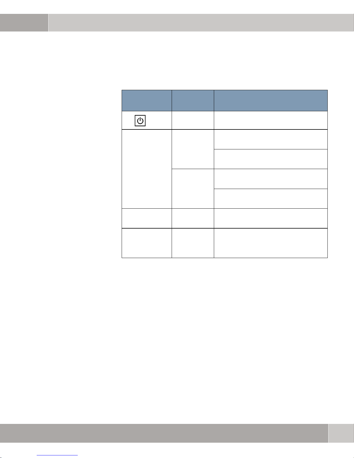
The following table describes the LEDs and their significance:
2
LED
designation
LINK Orange ON: 10 Mbps connection established at
WLAN Green BLINKING:Sending or receiving data via
WPS
button/LED
Color Description
Steady green Power supply established.
LAN port.
BLINKING: Sending or receiving data via
the LAN port.
Green ON: 100 Mbps connection established at
LAN port.
BLINKING: Sending or receiving data via
the LAN port.
the wireless connection.
-----
After activating WPS in "Push
Button" mode, to be used as
described in
Chapter 4.2.1.
User Manual
11
Page 12
2
Hardware Installation
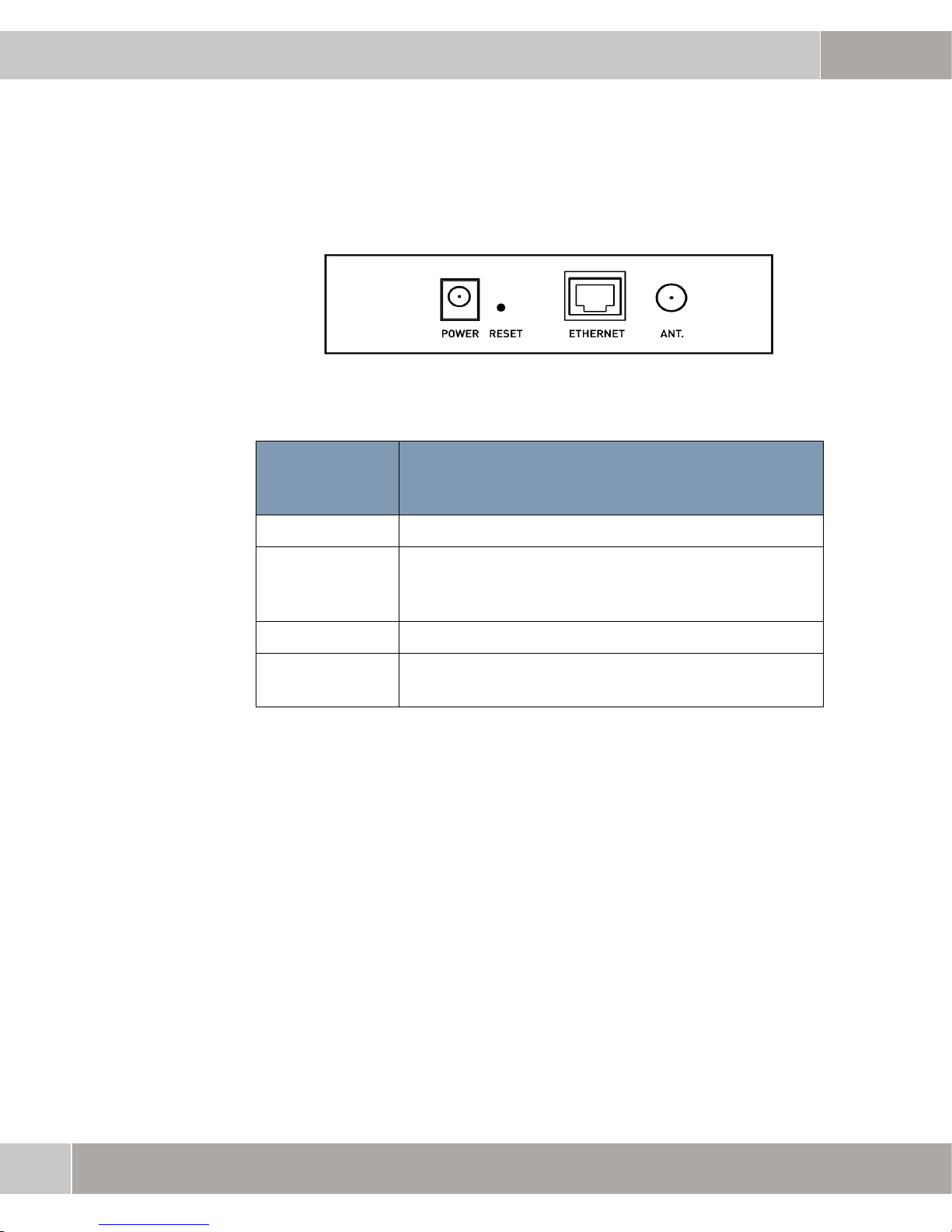
W500 rear panel:
Connection/
operating
element
Description
POWER Power supply: 12 V DC, 1.0 A (min.).
RESET The Reset button resets the system settings to the factory
defaults. Keep the Reset button depressed for at least
three seconds. After releasing the button W500 reboots.
ETHERNET LAN port 10/100 Mbps Ethernet
ANT The antenna is included with the device. Please screw the
antenna into the jack (ANT) and align it vertically.
2.4 Hardware Installation
Perform the following steps to set up W500.
Select Location Decide on the location of W500 before installation. The location must be care-
fully selected in order to ensure the best radio range for W500. The most favorable location for installing W500 is usually at the center of the required radio
coverage area. Attempt to install the mobile stations within line of sight of
Obstacles can impair the performance of
W500.
W500.
12
User Manual
Page 13

Hardware Installation
Positioning W500 You can place W500 on a flat surface such as a table or cupboard or mount the
unit upright e.g. on a wall. The W500 antenna works best in an open environment with as few obstacles as possible.
2
Connecting the
Ethernet Cable
Establishing Power
Supply
Note
Defining Settings for
Wireless Devices
W500 supports a 10/100 Mbps Ethernet connection. Connect one end of the
Ethernet cable to the W500 RJ-45 connector. Connect the other end of the RK45 cable with a switch, hub or computer.
Connect the power supply unit with the power supply. W500 automatically starts
a self-test. Wait for around a minute until the WLAN LED is lit steady and
switches to normal operation.
The W500 access point must only be operated with the approved power supply
unit supplied.
For accessing W500 the wireless devices (802.11b or 802.11g standard) must
be configured according to the
as follows:
NETWORK NAME: Funkwerk-ec
CHANNEL: 6
OPERATING MODE: AP
W500 settings. The default settings for W500 are
W500
Note
WLAN SECURITY: OFF
It is strongly recommended to set WLAN SECURITY to ON and to change the
W500 security mode fromdisabled (default settings) to WPA2-PSK
(recommended setting). Please find the necessary setup steps in
4.2.4 (Setting Security Mode).
Chapter
User Manual
13
Page 14

2
Hardware Installation
14
User Manual
Page 15

Configuration
3 Configuration
W500 allows IP configuration via the ComPoint Manager and detailed set-
up with a web browser.
3.1 Access to the Web-based
Configuration Program
If you do not wish to use the fixed W500 IP address192.168.0.252, please install
the ComPoint Manager software. You can find it on the product CD or on our
website. ComPoint Manager allows you to localize
without difficulty and define another IP address suitable for the network. The
use of ComPoint Manager is explained in the documentation for this tool.
W500 within your network
3
Note
Not all functions of FEC ComPoint Manager are available for W500. The
localization of devices in the network and the IP configuration of FEC devices
are supported. Please note that
WLAN management software applications WILMA or WMS.
The following instructions guide you through the installation of W500 with the
example of its preset IP address.
1. Connect your computer wireless or via a cable to W500. Please set a fixed
IP address on your computer. It must be in the range 192.168.0.X, whereby
"X" must not be 254 or 252. If you wish to establish a wireless connection,
you first have to set the configuration described below in the computer.
– SSID: Funkwerk-ec
HANNEL: 6
– C
– WLAN
– O
– WLAN: ON
2. Open your web browser, in the address field enter the W500 IP address
and press Enter. The
SECURITY: disabled
PERATION MODE: AP
W500 standard address is http://192.168.0.252.
W500 is not compatible with the Funkwerk
User Manual
15
Page 16

3
Configuration
3. The USER is ’admin’ and the default PASSWORD is ’funkwerk’.
The web-based configuration program offers you several options for monitoring
and configuring
After logging on you arrive at the homepage. Here you find the buttons Status,
System, Wireless LAN, Management and Monitoring. The main menu contains links to all parts of the web configuration interface.
W500.
16
User Manual
Page 17
Configuration
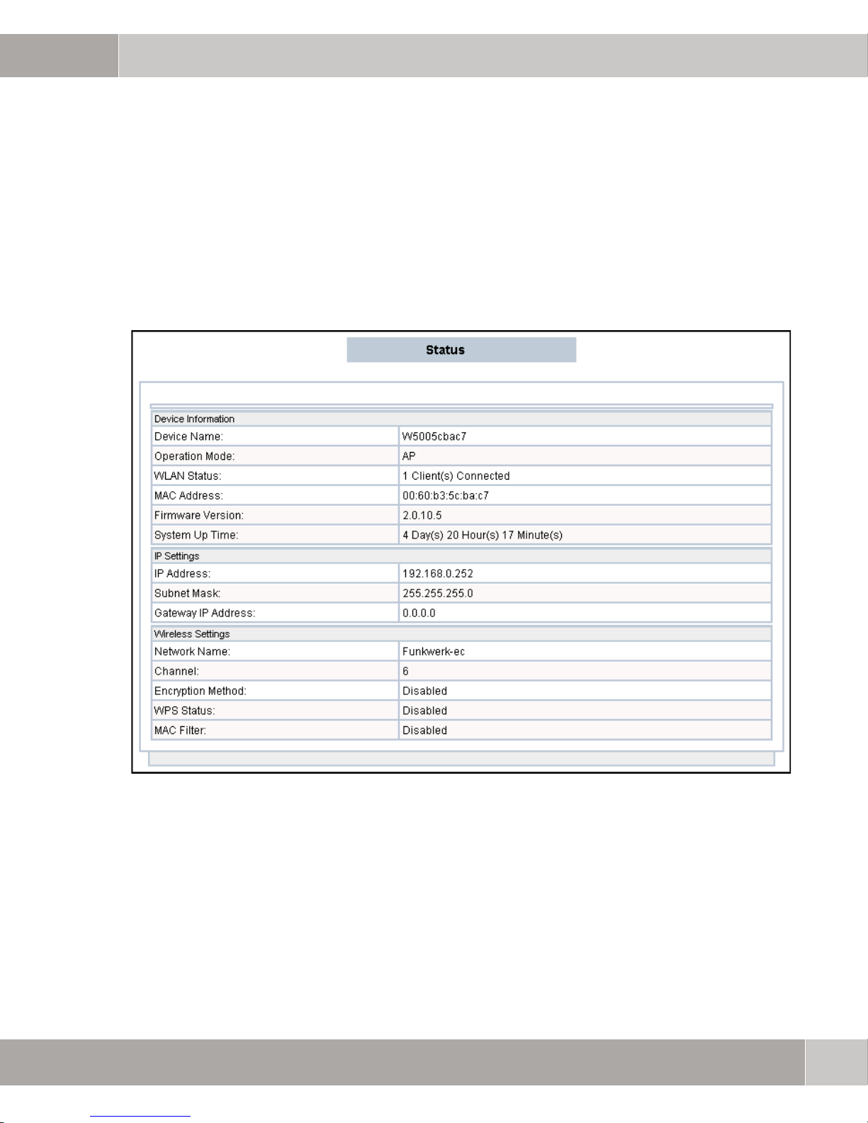
3.1.1 Status
The STATUS page offers a brief description of the device and its status. The displayed device status includes DEVICE INFORMATION, IP SETTINGS and WIRELESS
ETTINGS.
S
3
Figure 3-1: Status
User Manual
17
Page 18
3
Configuration
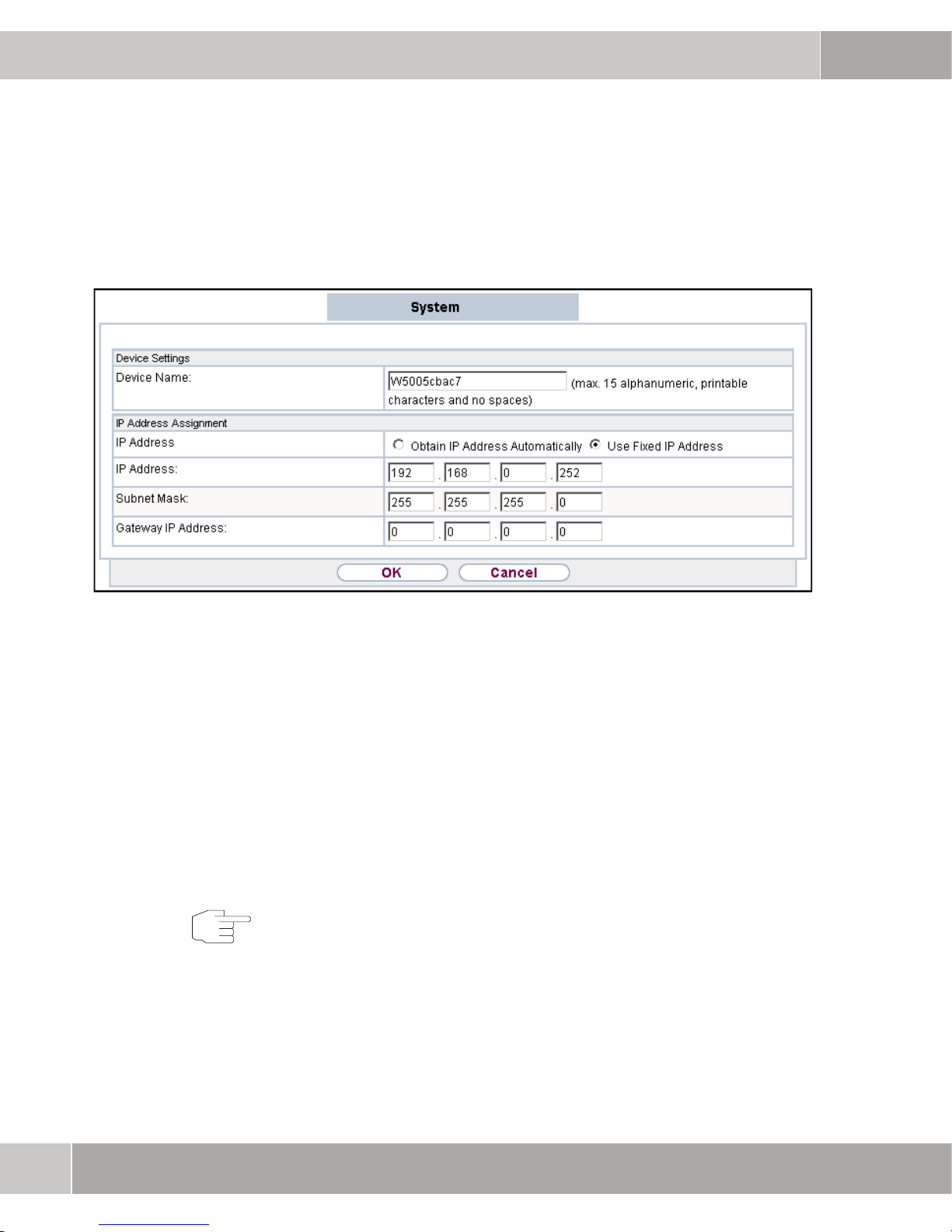
3.1.2 System
Note
Figure 3-2: System
DEVICE SETTINGS: The device name serves to identify your access point. The default is W500 plus the 6 last digits of the MAC address.
This makes it easier for you to manage your access point if there are several
APs in your network. You can also use the name of the AP for web management
access (e.g. http://W5005cbac7).
IP ADDRESS ASSIGNMENT: You can define the IP address for your access point in
this section. You have the option of using a fixed IP address or of obtaining the
IP address automatically using DHCP.
On completion of the settings, click OK to implement the changes.
18
User Manual
Page 19
Configuration
3.2 Wireless
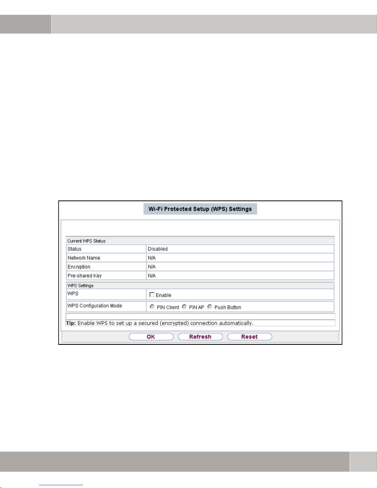
3.2.1 WPS Settings
The WPS (Wi-Fi Protected Setup) specification is overseen by the Wi-Fi Alliance and primarily serves to simplify setup and management of security functions for Wi-Fi networks.
The access point supports three WPS configuration methods: Client's PIN,
AP's PIN and Push Button. To enable the WPS function click the check box
ENABLE WPS.
3
PIN Client After selecting the WPS configuration method PIN Client enter the PIN and the
Figure 3-3: WPS settings
pre-shared key generated from the WPS wireless client on attempting to estab
lish connection with the AP. Alternatively, you can enter your own PSK. Click
OK to immediately start the WPS process.
User Manual
-
19
Page 20

3
Configuration
PIN AP
Push Button W500 supports software PBC (calling up WPS mode from a software button)
If the PIN AP WPS configuration method is selected, the AP automatically generates a PIN. Click OK to save the configuration and to enter the generated PIN
in the wireless client WPS program. In this case, start the process start from the
wireless client WPS program.
and hardware PBC (calling up WPS mode by pressing a button on the device).
To use software PBC, select
ter the pre-shared key. Click Start PBC to start the WPS process. If you wish to
use the hardware WPS button, the
Keep the Hardware WPS button depressed for at least three seconds. After releasing the button the AP switches to the WPS mode for two minutes. During
these two minutes you have to arrange for the wireless client to establish a WPS
connection with the AP using the same PBC mode.
WPS Configuration Mode Push Button and en-
WPS Enable check box must be selected.
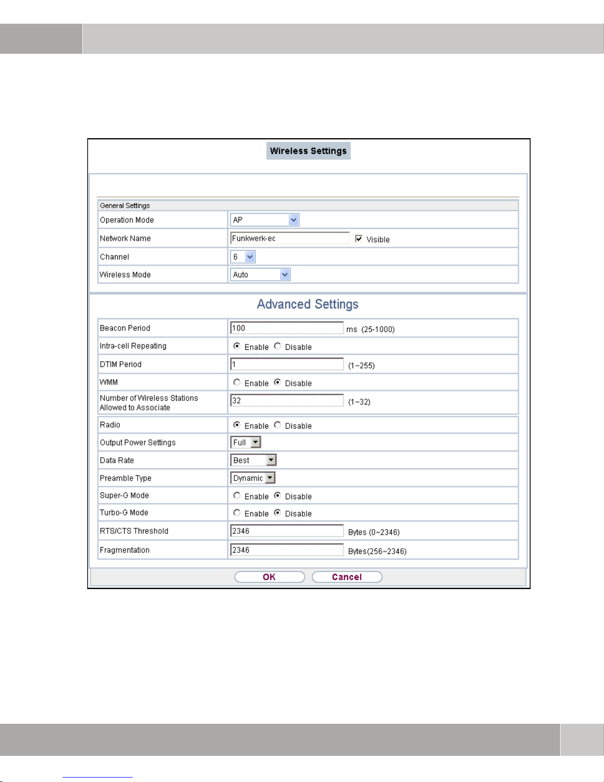
3.2.2 Wireless Settings
In this menu you can undertake changes to the settings for wireless network operation. In GENERAL SETTINGS changes can be made to OPERATION MODE,
NETWORK NAME, CHANNEL and WIRELESS MODE, in ADVANCED SETTINGS additional
parameters such as
for changing.
OUTPUT POWER or DATA RATE MANAGEMENT are accessible
20
User Manual
Page 21
Configuration
3
Figure 3-4: Wireless settings
User Manual
21
Page 22

3
Configuration
Fields in the General Settings menu
Field Description
OPERATION MODE Define in which mode the wireless module of
your device is to be operated
Selectable parameters:
– Access point:
Your device serves as an access point
in your network.
– Bridge:
Your device serves as a wireless
bridge in your network.
The device can act as a wireless
network bridge and establish wireless
connections to other APs. In this case,
you have to know the MAC address of
the other peer devices, which must also
be in bridge mode.
If two APs are connected in bridge
mode, they form a WDS (Wireless
Distribution System), which allows
computers in a LAN to establish
contact with the computers in another
LAN.
– AP+Repeater:
Select AP+Repeater as operation
mode if the device is to work as an
access point and wireless bridge.
– Wireless Client:
In this mode the device behaves like a
wireless client connected with a
wireless network.
22
User Manual
Page 23

Configuration
Field Description
NETWORK NAME (SSID): The NETWORK NAME (SSID) is an identification
used by access points and stations, which is
unique for a WLAN.
The standard SSID is funkwerk-ec. To change
this, please enter the required name of the
wireless network. The SSID must consist of a
maximum of 32 ASCII characters.
Also select whether the NETWORK NAME (SSID)
is to be transferred. The function becomes
enabled with the selection of
to enabled by default.
Visible. This is set
3
CHANNEL: Select the channel from the list box, which is
appropriate for your network settings.
WIRELESS MODE: Select the wireless technology, which the
access point is to use.
Selectable values:
– AUTO: default value. Your device
adapts to the technology (802.11b or
802.11g) of the clients.
ONLY 802.11b: Your device works
–
exclusively to 802.11b and the clients
must adapt accordingly.
–
ONLY 802.11g: Your device works
exclusively to 802.11g and the clients
must adapt accordingly. 802.11b
clients do not have access.
User Manual
23
Page 24
3
Configuration
Fields in the WDS Settings menu
Field Description
LOCAL MAC ADDRESS: The MAC address of the device.
REMOTE MAC ADDRESS
1-4:
Enter the MAC address of the peer device in a
format valid for MAC addresses (six
hexadecimal character pairs).
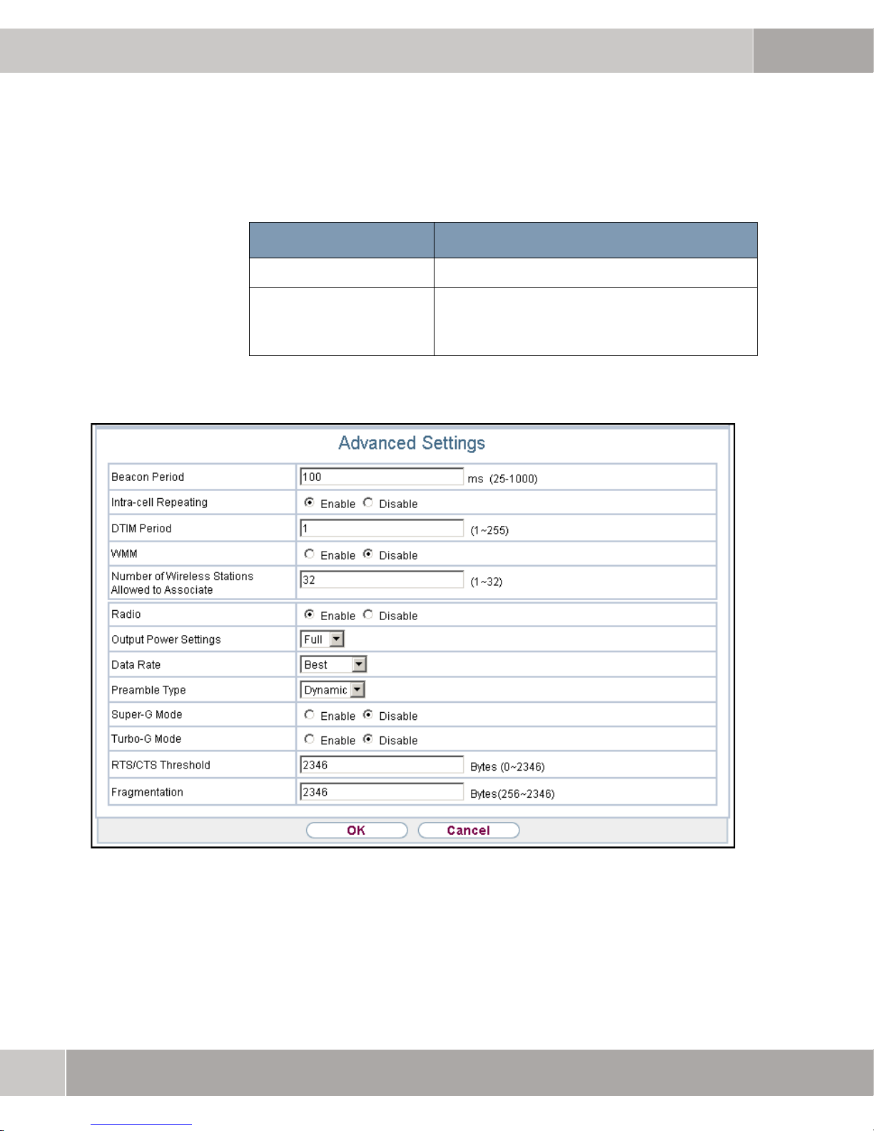
Figure 3-5: Advanced settings
24
User Manual
Page 25

Configuration
Fields in the Advanced Settings menu
Field Description
BEACON PERIOD: Enter the time in milliseconds between sending
two beacons.
This value is transferred to Beacon and Probe
Response Frames.
The default value is 100 msec.
INTRA-CELL REPEATING: Select whether communication between the
WLAN clients within a wireless cell is to be
allowed
The function becomes enabled with the
selection of
Enabled.
3
By default, the function is Enabled.
DTIM PERIOD: Specify the interval for the Delivery Traffic
Indication Message (DTIM).
The DTIM field is a data field in the transmitted
beacons, which informs clients about the next
broadcast or multicast transmission. If the
clients are operated in the power-saving mode,
they will wake up in time and will receive the
data.
Values are possible between 1 and 255
The default value is 1.
User Manual
25
Page 26

3
Configuration
Field Description
WMM: Select whether WMM (Wireless Multimedia) is
to be enabled for wireless network voice or
video data prioritization, in order to always attain
the best possible transmission quality for timecritical applications. DSCP (Differentiated
Services Code Point) or IEEE802.1d data
prioretization is supported.
The function becomes enabled with the
selection of
Enabled.
NUMBER OF CLIENTS
ALLOWED TO BE LOGGED
ON AT THE SAME TIME:
Use this field to define the maximum number of
wireless stations that can have a connection
with the device.
Enter the number (1 to 32) of permissible
wireless stations.
RADIO: Enable the wireless adapter to allow wireless
communication between the device and other
devices in accordance with IEEE802.11b or
IEEE802.11g standards. Disable the wireless
adapter to terminate wireless communication
between the device and other devices in
accordance with IEEE802.11b or IEEE802.11g
standards.
OUTPUT POWER: Defines the output power of the access point.
The options are
default setting (
Full, 50%, 25%, 12%, Min. The
50%) is matched to the 5dBi
antenna supplied. The output power must not
be increased when using the 5dBi antenna.
26
User Manual
Page 27

Configuration
Field Description
DATA RATE MANAGEMENT The underlying transmission rate should be
selected dependent on the speed of the
wireless network. The value determines this
transmission rate. From the drop-down menu
select
possible transmission rate.
PREAMBLE TYPE: The preamble defines the length of the PLCP
synchronization field for communication
between the access point ad the network
interface card. The default setting is
SUPER-G MODE: Enabling the Super-G mode can improve the
wireless data throughput. The default setting is
Disabled.
Best, to always achieve the highest
Dynamic.
3
TURBO-G MODE: Enabling Turbo-G can improve the wireless
data throughput up to 108 Mbps. Please note
that to use this mode the wireless client also has
to support the Turbo-G mode. The default
setting is
NOTE: Only certain WLAN devices and WLAN
clients support this mode.
RTS/CTS THRESHOLD: The RTS Threshold serves to prevent the
occurrence of hidden node problems. RTS is
activated if the size of the packet sent is larger
than a defined value. If RTS is activated, the
station and your access point use a RTS/CTS
method for data transmission. The setting range
extends from 0 to 2346.
Disabled.
User Manual
27
Page 28

3
Configuration
Field Description
FRAGMENTATION: Specify the maximum size above which the data
packages are fragmented (i.e. divided into
smaller units). Low values in this field are
recommended in areas with poor reception and
interference.
Values are possible between 256 and 2346
The default value is 2346 bytes.
On completion of the settings, click OK to implement the changes.
Note
3.2.3 Security
As WLAN data are sent via the transmission medium of open space, data can,
in theory, be intercepted and read by anybody with the appropriate means. For
this reason, the protection of the wireless link deserves special attention.
Access control
By creating an access control list (ACL mode or MAC filter), you can control
which clients are allowed to access your wireless LAN. In the access control list,
specify the MAC addresses of the clients which are allowed to access to your
wireless LAN. Access is denied to all other clients.
28
User Manual
Page 29
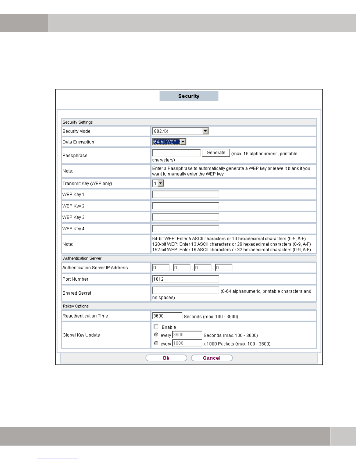
802.1x authentication
Configuration
3
Figure 3-6: 802.1x security
User Manual
29
Page 30

3
Configuration
Field Description
SECURITY MODE: 802.1x authentication:
IEEE 802.1x is a standard for network access
control (port-based), specially introduced for
distributing cryptographic keys in a wireless
network. The access point supports IEEE
802.1x to repel non-authorized users and to
check the authorization of users with RADIUS
so that authorized users obtain access to the
network and services.
To use IEEE 802.1x you require a common
Extensible Authentication Protocol (EAP) on
your authorization server, the APs
(authenticator) and the stations (requestor).
IEEE 802.1x is also used to generate and
distribute cryptographic keys from the AP to the
station as part of the authentication process.
Another factor here is the dynamic WEP. It is
based on old RC4 WEP encryption and with this
access point is available under the setting to
enable
disabled
settings. Key lengths are selectable as 64 or
128 bit. The longer the key, the greater the
security it offers.
DATA ENCRYPTION: After clicking the button Set WEP Key you can
define the
Passphrase for the WEP key.
IEEE 802.1x security in association with
Wired Equivalent Privacy (WEP)
Length, Format, Key Index and
30
User Manual
Page 31

Configuration
Field Description
PASSPHASE: You can also input the PASSPHRASE manually:
64-BIT WEP: Enter five ASCII characters or 10
hexadecimal values (between 0-9, a-f and A-F).
128-BIT WEP:Enter 13 ASCII characters or
hexadecimal values (between 0-9, a-f and A-F).
152-BIT WEP: Enter 16 ASCII characters or 32
hexadecimal values (between 0-9, a-f and A-F).
3
TRANSMISSION KEY
(WEP ONLY):
AUTHENTICATION SERVER
IP A
DDRESS:
PORT NUMBER: Enter the associated port for RADIUS data.
SHARED SECRET: Enter your shared password for communication
REAUTHENTICATION TIME: Here you can enter the time interval within
Select one of the keys configured in WEP Key
<1-4> as the standard key.
The default value is Key 1.
Enter the IP address of the RADIUS server.
According to RFC 2138, the standard ports
reserved are 1812 for authentication (1645 in
older RFCs) and 1813 for billing (1646 in older
RFCs). You can find out which port is to be
used from the documentation on your RADIUS
server.
The default value is 1812.
between the RADIUS server and your device.
which the connection is reauthenticated.
The default value is 3600.
GLOBAL KEY UPDATE Here you can define whether the key to protect
the connection is renewed at regular intervals.
You can select between renewal after a certain
period of time or on receipt and/or transmission
of a certain number of packets.
The default status of this function is disabled.
User Manual
31
Page 32

3
Configuration
WEP
Figure 3-7: Security WEP
32
User Manual
Page 33

Configuration
Field Description
SECURITY MODE: WEP:
802.11 defines the WEP (Wired Equivalent
Privacy) security standard.
The widely use WEP standard has been shown
to be susceptible. Hence, the WPA or WPA2
pre-shared key should preferably be used.
AUTHENTICATION TYPE: OPEN: Requires no authentication, as it allows
the participation of all the devices in the
network without a previous security check. The
authentication method is set to
settings.
Open in the pre-
3
SHARED KEY: The station and access point must
use the same WEP key for authentication.. In
simple terms, WEP must be enabled and
configured for the
the same key used. All points in the network
must use the same authentication method.
DATA ENCRYPTION: After clicking the button Set WEP Key you can
define the
Passphrase for the WEP key.
PASSPHASE: You can also input the PASSPHRASE manually:
64-BIT WEP: Enter five ASCII characters or 10
hexadecimal values (between 0-9, a-f and A-F).
128-BIT WEP:Enter 13 ASCII characters or
hexadecimal values (between 0-9, a-f and A-F).
152-BIT WEP: Enter 16 ASCII characters or 32
hexadecimal values (between 0-9, a-f and A-F).
TRANSMISSION KEY
(WEP ONLY):
Select one of the keys configured in WEP Key
<1-4> as the standard key.
The default value is Key 1.
Length, Format, Key Index and
access point and client and
User Manual
33
Page 34

3
Configuration
Note
The WEP passphrase must be exactly the same for wireless clients and W500.
If you define
stations the WEP passphrase 0011223344
WPA & WPA2
W500 offers WPA and WPA2 setting options for even higher security in wireless
network operation. Wi-Fi Protected Access (WPA) is part of the IEEE 802.11i
standard. WPA2 is a wireless security standard, which, compared with WPA, of
fers more effective encryption, authentication and key management.
0011223344 for W500, you also have to assign all other client
.
-
Figure 3-8: WPA & WPA2 security
34
User Manual
Page 35

Field Description
SECURITY MODE: WPA
WPA (Wi-Fi Protected Access) offers additional
protection with dynamic keys, based on the
Temporal Key Integrity Protocol (TKIP) and
offering authentication of users’ PSK (Pre
Shared Keys) or the Extensible Authentication
Protocol (EAP) with 802.1x (e.g. RADIUS).
Authentication via EAP is generally used in
large wireless LAN installations, as this requires
an authentication service in the form of a server
(e.g. a RADIUS server). PSKs are generally
used in smaller networks, as often occur in
SoHo (Small Office, Home Office)
environments. The corresponding PSK must
therefore be known to all subscribers in the
wireless LAN, because it is used to generate the
session key.
Configuration
3
AUTHENTICATION SERVER
IP A
DDRESS:
WPA2
The advancement on WPA is WPA2. Not only
has the 802.11i standard been fully
implemented in WPA2, but it also uses another
encryption algorithm (AES, Advanced
Encryption Standard).
Enter the IP address of the RADIUS server.
User Manual
35
Page 36

3
Configuration
Field Description
PORT NUMBER: Enter the associated port for RADIUS data.
According to RFC 2138, the standard ports
reserved are 1812 for authentication (1645 in
older RFCs) and 1813 for billing (1646 in older
RFCs). You can find out which port is to be
used from the documentation on your RADIUS
server.
The default value is 1812.
SHARED SECRET: Enter your shared password for communication
between the RADIUS server and your device.
REAUTHENTICATION TIME: Here you can enter the time interval within
which the connection is reauthenticated.
The default value is 3600.
GLOBAL KEY UPDATE Here you can define whether the key to protect
the connection is renewed at regular intervals.
You can select between renewal after a certain
period of time or on receipt and/or transmission
of a certain number of packets.
The default status of this function is disabled.
WPA Authentication
Mode:
WPA Cipher Suite: Using WPA as the encryption method, the WPA Cipher presetting is TKIP only.
WPA2 Cipher Suite: Using WPA2 as the encryption method, the WPA Cipher presetting is AES only.
W500 offers two selection options: Enterprise (RADIUS) and Personal (PreShared Key)
data, otherwise you have to enter the pre-shared key format and the passphrase.
. After selecting Enterprise you have to enter the RADIUS server
36
User Manual
Page 37

Note
Configuration
WPA-PSK & WPA2-PSK
The security modes are available both in pure form, as well as in mixed form.
3
Note
Figure 3-9: WPA-PSK & WPA2-PSK security
Windows XP as a client operating system requires at least SP2 and update KB
893357 for WPA2.
User Manual
37
Page 38

3
Configuration
3.2.4 MAC Address Filter
The MAC address filter allows the configuration of the AP such that the access
point only allows certain wireless stations exclusive access or selected stations
are denied this access. To enable the WPS filter function, click the check box
beside
enter the MAC address of the wireless client in order to allow the specified wire
less stations access to the wireless network. Alternatively, select Deny the
following MAC Address to associate
stations access to the wireless network.
Enable. Select Allow the following MAC Address to associate and
in order to deny the specified wireless
-
38
User Manual
Page 39

Configuration
3
Figure 3-10: MAC Address Filter
User Manual
39
Page 40

3
Configuration
3.3 Management
3.3.1 Password
Here you can change the password for the access point as explained below.
Note
Figure 3-11: Password
1. To change the current password, select in the Management section the option Password on the left hand side.
2. Enter the new password for W500 into the field NEW PASSWORD. Repeat entry in the field RETYPE TO CONFIRM. Click on OK to save the setting.
Make a note of the new password. Otherwise you can no longer access the
W500 user interface. Should you ever forget the password, you can revalidate
the preset password. Press the reset button on the back of
three seconds. Then all the previous configuration steps also have to be
performed again.
On this page you can check the current status and the general settings for
W500.
W500 for at least
40
User Manual
Page 41

Configuration
3.3.2 Configuration File
On this page you can back up the current settings to a file or restore on the basis
of the file.
3
Figure 3-12: Configuration
BACKUP CONFIGURATION: Backup the current configuration to the computer.
RESTORE CONFIGURATION: Restore the configuration from a previously saved
configuration file.
BACK TO FACTORY DEFAULTS: The Reset button clears all user-entered configuration settings and resets the device back to its factory default settings.
■ PASSWORD: funkwerk
■ LAN IP ADDRESS: 192.168.0.252
User Manual
41
Page 42

3
Configuration
3.3.3 Upgrade Firmware
On this page you can upgrade the firmware via the Web.
Warning!
Figure 3-13: Firmware Import
With Firmware Import you can update the W500 firmware to the latest version.
Please ensure that you have downloaded the latest and correct firmware from
the product support website and have saved it to a local drive before you undertake the upgrade of the W500 firmware.
To upgrade to the latest firmware, localize the file by clicking the button Search
and then clicking Upload to start the upgrade process. Upgrading the firmware
takes around seven minutes. If the firmware upgrade fails, repeat the steps de
scribed above.
Never switch off the device during the upgrade. The result of interrupted
upgrading operations could be that your gateway no longer boots.
-
42
User Manual
Page 43

Configuration
3.4 Monitoring
3.4.1 Logs
You can view log entries and alarm messages on the screen. As soon as the
log table is full, new log entries replace the oldest entries.
3
Figure 3-14: Log List
Click Refresh to update the log table.
Click Clear Log to delete all the entries.
User Manual
43
Page 44

3
Configuration
3.4.2 Statistics
Figure 3-15: Statistics
The AUTOMATIC REFRESH INTERVAL specifies after how many seconds the display
of statistical information is refreshed.
onds depending on the entry; Stop halts the refreshing process.
Under ETHERNET the number of packets or bytes sent or received via the RJ45
Ethernet interface is displayed.
Under WIRELESS the number of packets or bytes sent or received via the WLAN
Radio interface is displayed as a total sum and also itemized in parts
(one to one), Broadcast (one to all) and Multicast (one to several).
Set Interval changes the number of sec-
Unicast
44
User Manual
Page 45

Configuration
3.4.3 List of Associated Devices
Figure 3-16: List of Associated Devices
The list of associated devices (ASSOCIATION LIST) shows those WLAN clients
that are connected to the SSID of the AP.
3
The list displays the serial number (#), the MAC address of the WLA client (MAC
ADDRESS), the IP address of the WLA client (IP ADDRESS), the signal strength of
the wireless connection in percent (SIGNAL STRENGTH) and the STATUS of the
WLAN client to the SSID of the AP (normally
Associated).
User Manual
45
Page 46

3
Configuration
46
User Manual
Page 47

Use of the Device in Various Network Scenarios
4 Use of the Device in Various
Network Scenarios
W500 can be used for different network scenarios, as described below.
4.1 Bridge Mode with WEP
In bridge mode, two W500s are linked together and this connection is used to
couple two LANs. The two W500s in bridge mode do not offer an access point
function, i.e. no clients can be connected with the W500s in bridge mode.
4
Figure 4-1: Bridge mode
4.1.1 Login
To establish the connection with the web browser, log in with user name and
password (the standard IP address is 192.168.0.252, the standard user name
admin and the standard password is funkwerk). The language can also be
is
selected on the Login page (
English or German).
User Manual
47
Page 48

4
Use of the Device in Various Network Scenarios
Figure 4-2: Login
4.1.2 Navigation Menu
The initial setting is made in WIRELESS LAN - WIRELESS SETTINGS. Figure 4-3
shows the navigation menu from the left section of the screen.
48
User Manual
Page 49

Use of the Device in Various Network Scenarios
4
Figure 4-3: Navigation bar
4.1.3 Setting Operation Mode
Here (WIRELESS LAN - WIRELESS SETTINGS) W500 is assigned the OPERATION
ODE Bridge.
M
User Manual
49
Page 50

4
Use of the Device in Various Network Scenarios
Figure 4-4: Setting Operation Mode
4.1.4 Advanced Settings / Setting MAC Address
After setting the CHANNEL and activating RADIO (ADVANCED SETTINGS) the MAC
address of the second bridge, with which the connection is to be established,
has to be specified. In turn, the bridge mode is also selected on the second
W500 and the MAC address of the first bridge is specified. Confirm with OK.
50
User Manual
Page 51

Use of the Device in Various Network Scenarios
4
Note
Figure 4-5: Entry of the MAC address
Setting the Security Mode.
In bridge mode, only the security mode WEP is supported.
Configuration takes place in WIRELESS LAN - SECURITY. In Figure 4-6 configuration with WEP is shown. After selecting the security mechanism, a freely select-
User Manual
51
Page 52

4
Use of the Device in Various Network Scenarios
able WEP key (default key is WEP KEY 1) must be configured. Follow the
instructions on the screen. Confirm with OK.
Figure 4-6: Security Mode
4.1.5 Checking Status
On the Status page (menu item STATUS in the navigation bar) the operation
mode entries and the WLAN status show that the configuration of the bridge and
establishment of the connection to the second bridge was successful.
52
User Manual
Page 53

Use of the Device in Various Network Scenarios
4
Figure 4-7: Status
4.2 Access Point Mode with WPA2-PSK
and MAC Filter
In this mode clients are connected via WLAN to the access point. They can then
communicate with other WLAN clients or clients in the wired LAN.
User Manual
53
Page 54

4
Use of the Device in Various Network Scenarios
Windows XP as a client operating system requires at least SP2 and update KB
893357 for WPA2.
Note
Figure 4-8: Access point mode
4.2.1 Login
For configuration, firstly the Web interface of the access point is called up with
the aid of the browser and login is performed with user name and password.
The standard IP address is
the standard password
gin page (English or German).
192.168.0.252, the standard user name admin and
funkwerk. The language can also be selected on the Lo-
54
User Manual
Page 55

Use of the Device in Various Network Scenarios
4
Figure 4-9: Login
4.2.2 Navigation Menu
In the menu on the left hand side in WIRELESS LAN the item WIRELESS SETTINGS
is selected.
User Manual
55
Page 56

4
Use of the Device in Various Network Scenarios
Figure 4-10: Navigation bar
4.2.3 Setting Operation Mode
The OPERATION MODE is selected as AP. The NETWORK NAME (SSID) must also
be configured. This can be made visible or invisible. In Wireless Mode it can be
determined whether
802.11b, 802.11g or both (Auto) are supported.
56
User Manual
Page 57

Use of the Device in Various Network Scenarios
4
Figure 4-11: General settings
RADIO must be enabled in the ADVANCED SETTINGS. On conclusion, confirm the
entry with
OK.
User Manual
57
Page 58

4
Use of the Device in Various Network Scenarios
58
User Manual
Figure 4-12: Enabling Radio
4.2.4 Setting the Security Mode
In order to achieve an encrypted WLAN connection to the clients, the encryption
type must be selected in the Security menu item. In this example, the encryption
method
WPA2-PSK is selected.
Page 59

Figure 4-13: Security mode
Use of the Device in Various Network Scenarios
4
Next of all, enter the freely selectable PRE-SHARED KEY. The key must also be
entered for the relevant clients. The maximum length of 63 ASCII characters
should be fully exploited to make the key as secure as possible. On conclusion,
confirm the entry with
Figure 4-14: Pre-shared key
OK.
User Manual
59
Page 60

4
Use of the Device in Various Network Scenarios
Configuration of a MAC address filter takes place in WIRELESS LAN - MAC
FILTER. Here the MAC address of a client that is allowed to use the access point
is now entered. On conclusion, confirm the entry with
OK.
Figure 4-15: MAC Address Filter
60
User Manual
Page 61

Use of the Device in Various Network Scenarios
4.2.5 Checking Status
In the menu item MONITORING – ASSOCIATION LIST an entry for this device can be
seen if a client is logged in.
Figure 4-16: List of associated devices
4
The Status display offers the possibility of gaining an overview of the security
configured.
User Manual
61
Page 62

4
Use of the Device in Various Network Scenarios
62
Figure 4-17: Status
4.3 AP + Repeater Mode with WPA2-PSK
This scenario offers the possibility of expanding a wireless cell with a second
W500. Both access points are set to the "AP+Repeater" mode. The two devices
are connected together via WLAN and at the same time provide their WLAN interface for connecting clients.
User Manual
Page 63

Use of the Device in Various Network Scenarios
4
Figure 4-18: AP + Repeater mode
4.3.1 Login
The connection to W500 is established with a browser. The standard IP address
is 192.168.0.252, the standard user name admin and the standard password
funkwerk. The language can also be selected on the Login page (English or
German).
User Manual
63
Page 64

4
Use of the Device in Various Network Scenarios
Figure 4-19: Login
4.3.2 Navigation Menu
Configuration starts in WIRELESS LAN - WIRELESS SETTINGS.
64
User Manual
Page 65

Figure 4-20: Navigation bar
Use of the Device in Various Network Scenarios
4
4.3.3 Setting Operation Mode
The OPERATION MODE is selected as AP+Repeater.
Figure 4-21: Setting Operation Mode
User Manual
65
Page 66

4
Use of the Device in Various Network Scenarios
Besides configuring the CHANNEL and enabling RADIO, the MAC address of an
access point is also entered, which acts as a repeater and is logged on to this
access point. In turn, the MAC address of this access point must be entered at
the second access point. This entry is confirmed with
OK.
Figure 4-22: Further settings
66
User Manual
Page 67

Use of the Device in Various Network Scenarios
4.3.4 Setting the Security Mode
For AP+Repeater mode, the security selection can be made in the WIRELESS
LAN - S
must be specified for WPA2-PSK, which also has to be entered on the opposite
side. Confirm entry with
ECURITY menu between WEP and WPA2-PSK. A freely selectable PSK
OK.
4
Figure 4-23: Security Mode
4.4 Wireless Client Mode with WPA2-PSK
In this scenario, a W500 is configured as a client and can log on at a central AP
as such. A PC can be connected to the wireless client, which can use the wire
less client AP as a WLAN interface, as it were.
Firstly a W500 or another access point must be configured as an AP with a corresponding network name (SSID), channel settings and security. This takes
place as in the AP mode scenario.
-
User Manual
67
Page 68

4
Use of the Device in Various Network Scenarios
4.4.1 Login
For configuration, firstly the Web interface of the access point is called up with
the aid of the browser and login is performed with user name and password.
The standard IP address is
and the standard password is funkwerk. The language can also be selected on
the Login page (
English or German).
192.168.0.252, the standard user name is admin
Figure 4-24: Login
4.4.2 Navigation Menu
In the menu on the left hand side in WIRELESS LAN the item WIRELESS SETTINGS
is selected.
68
User Manual
Page 69

Figure 4-25: Navigation bar
Use of the Device in Various Network Scenarios
4
4.4.3 Setting Operation Mode
The OPERATION MODE is selected as AP. The NETWORK NAME (SSID) must also
be configured. This can be made visible or invisible. In Wireless Mode it can be
determined whether
802.11b, 802.11g or both (Auto) are supported.
User Manual
69
Page 70

4
Use of the Device in Various Network Scenarios
.
Figure 4-26: General settings
RADIO must be enabled in the ADVANCED SETTINGS. On conclusion, confirm the
entry with
OK.
70
User Manual
Page 71

Use of the Device in Various Network Scenarios
4
Figure 4-27: Enabling Radio
4.4.4 Wireless Client
Configuration of the wireless client begins with the menu item WIRELESS LAN -
IRELESS SETTINGS. Here the mode Wireless Client must first be selected.
W
User Manual
71
Page 72

4
Use of the Device in Various Network Scenarios
Figure 4-28: Operation Mode
Make sure that RADIO is enabled in the ADVANCED SETTINGS.
72
User Manual
Page 73

Use of the Device in Various Network Scenarios
4
Figure 4-29: Activating the air interface
The NETWORK NAME (SSID) is then entered in the same window. The SSID of
the client must correspond with the SSID of the access point to which the wire
less client is to be connected. The entry must be confirmed with OK.
User Manual
-
73
Page 74

4
Use of the Device in Various Network Scenarios
Figure 4-30: List of associated devices
4.4.5 Security Mode for the Wireless Client
The SECURITY MODE is entered in the next step. In our example, WPA2-PSK is
used for security. In
and the PRE-SHARED KEY entered. At the end the entry is confirmed with OK.
Figure 4-31: Security Mode
WIRELESS LAN - SECURITY the encryption type is selected
74
User Manual
Page 75

Use of the Device in Various Network Scenarios
4.4.6 Checking the Client’s Status
On the STATUS page it can be identified whether the wireless client is associated.
4
Figure 4-32: Checking Status
User Manual
75
Page 76

4
Use of the Device in Various Network Scenarios
76
User Manual
Page 77

Warranty
5Warranty
The development and production process is subject to comprehensive
quality management. This way we can offer our customers top quality
products. We guarantee the quality of our products in accordance with
the statutory warranty regulations. Warranty cases are handled by
your contractual partner, i.e. your dealer or distributor.
The period of warranty coverage for W500 is 24 months.
5
User Manual
77
Page 78

5
Warranty
5.1 Replacement, Repair and Refund for
Hardware
Should a power outage occur during a firmware upgrade or thereafter and functional faults result, please contact your supplier.
If the device has to be repaired or replaced, send it back to your suppler in the
original packaging. You have to enclose the following documents with a defec
tive device, which you send in during the warranty period.
■ Warranty repair card
■ Copy of the invoice or evidence of purchase and
■ RMA report form. Request an RMA form (Return Materials Authorization)
from your supplier.
-
After checking the purchasing slip, we will make our decision on repairing or replacing the defective part for the purchaser free of charge.
This warranty shall be granted under the condition that the product is used for
the intended purpose and in an appropriate way. Products expressly excluded
from the warranty are those modified without the consent of the manufacturer,
subjected to extraordinary mechanical or electrical stresses or have been dam
aged in other ways.
-
78
User Manual
Page 79

Warranty
Please fill out the following table and keep this information together with the
product.
Name:
Title:
Company:
Phone:
Fax:
e-mail:
ZIP-Code/City:
Country:
Product name:
5
Serial number:
MAC address:
Invoice date:
Product description:
Contact your authorized vendor in case of further questions.
User Manual
79
Page 80

5
Warranty
5.2 Technical Data
PRODUCT DESCRIPTION: IEEE 802.11g WLAN access point
ANTENNA: Detachable 5dBi RSMA antenna
OUTPUT POWER: 14 dBm + 5 dBm antenna gain
SENSITIVITY: 11g @ PER 10% 54 Mbps <= -65 dBm;
11b @ PER 8% 11 Mbps <= -80 dBm
MODULATION: 11g (OFDM) 64QAM, 16QAM, QPSK, BPSK;
11b (DSSS) CCK, DQPSK, DBPSK
RANGE: 11g: 54 Mbps up to 60 meters, 11 Mbps
up to 120 meters; 11b: 11 Mbps up to 80
meters, 1 Mbps up to 200 meters
FREQUENCY BAND: Europe (ETSI) 13 channels: 2.412 GHz –
2.472 GHz
INTERFACE
OPERATION MODES: access point, repeater, bridge and wireless
SECURITY: WPA/WPA2, 802.1x, WEP 64/128/154-bit
DIMENSIONS: 110mm x 125mm x 30mm (LxWxH)
WEIGHT: approx. 200g
TEMPERATURE RANGE:
AIR HUMIDITY: 90% (not condensing)
WARRANTY: 24 months
A 10/100 Base-T Ethernet interface with
Auto MDI(X) support
client
Operation 0 to 50°C, storage -10 to 65°C
80
User Manual
Page 81

6 Safety Precautions
Safety Precautions
Copyright © February 3, 2010 Funkwerk Enterprise Communications GmbH
Version 2.2
Page 82

6.1 General Safety Precautions in English
The following sections contain safety precautions you are strongly advised to
heed when handling your device.
Transport and storage ■ Transport and store your gateway in its original packaging only or use an-
other suitable packaging to protect the unit against impact and shock.
■ Please observe the transport and storage instructions attached to the pack-
aging.
Installation and initial
operation
■ Observe the information on the ambient conditions (cf. Technical Data and
Quick Install Guide) before installing and operating your gateway.
■ Please observe the respectively applicable framework conditions in your
country for the installation of external ISDN basic accesses. If and when required, consult a technician who has the corresponding licence. Obtain information about the special requirements of national regulations, and observe these legal requirements for the installation.
■ When the unit is moved from a colder environment into the workroom, con-
densation may occurr on the inside and outside of the unit. Allow the unit to
adapt to the temperature and to dry out completely before starting up oper
ation. Observe the environmental conditions rendered in the manual chapter titled Technical Data.
■ Make sure that shockproof (Home Office) socket used for the installation is
freely accessible. The mains plug has to be unplugged to disconnect the
unit from the mains completely.
■ Make sure that the value of the upstream fuses of the mains connection do
not exceed 16 amps.
■ Please check whether the rated voltage rendered on the typeplate of the
power supply unit corresponds to the local power supply.
-
■ In case of wall installation, please ensure that the screws are safely
screwed into the wall and can carry the weight of the unit and the cables.
■ Make sure that the antennas of local-area wireless network units are
screwed down tightly.
Page 83

Safety Precautions
■ Please make sure you follow the correct cabling sequence as described in
the Quick Install Guide.
■ Please check whether the cable connections are correct - in particular the
ISDN and LAN cables - before you start operating your gateway. The ISDN
connection of your gateway must not be connected to the Ethernet connec
tion of your PC or hub, and the LAN connection of your gateway must not
be attached to your ISDN connection.
■ Only use the cables enclosed or specified for cabling - as described in the
manual. If you use other cables, Funkwerk Enterprise Communications
GmbH shall not accept any liability for any damage occurring or for any ad
verse effects on the functions.
■ Please arrange the cables in such a way that they are no hazard (danger
of stumbling) and cannot be damaged.
6
-
-
Intended use and
operation
■ Do not connect, disconnect or touch the data transmission lines during
thunderstorms.
■ Your gateway is intended for use in an office environment. As a multi-pro-
tocol gateway, your gateway establishes WAN connections in keeping with
the system configuration. In order to avoid extra charges, it is imperative to
carefully monitor the unit.
■ Your gateway meets the relevant safety regulations for IT equipment when
used in an office environment. If you have any questions as to whether the
gateway can be set up in the intended environment, please get in touch with
your funkwerk dealer or with the funkwerk Customer Support Department.
■ The intended operation of the unit in keeping with European standard
60950 shall be ensured only when the unit cover has been fitted (cool-
EN
ing, fire protection, radio interference suppression).
■ The ambient temperature should not exceed +50 deg. Celsius. Avoid expo-
sure to direct sunlight. Ensure sufficient cooling.
■ Make sure no foreign objects (such as paper clips) or liquids get into the in-
side of the unit (electric shock, short-circuit).
■ Make sure that ventilation slits and orifices of the unit are not blocked.
Safety Precautions
83
Page 84

6
Safety Precautions
■ In cases of an emergency (such as damaged housing or operating element,
penetration of liquid or foreign objects), immediately interrupt the power
supply at the socket and notify the Service Department.
Local-area wireless
network
Cleaning and repair ■ The unit may be opened by trained specialist staff only. For this reason, re-
■ When the radio components are switched on, do not move the gateway into
the vicinity of inflammable gases or into a potentially explosive environment
(such as paint shop) as the radio waves emitted may cause an explosion
or fire.
■ The reach of the radio link depends on environmental and ambient condi-
tions.
■ Data traffic by a wireless connection may permit unauthorised third parties
to receive data. Depending on how critical the safety of the data transmitted
by WLAN are, carry out the necessary steps to secure your radio network.
pairs of the unit should be carried out only by a service centre authorised
by funkwerk. Your dealer will tell you where the service centre is located.
Unauthorised opening and improper repairs may result in considerable
hazards for the user (such as electric shock). Unauthorised opening of the
unit shall void guarantee and liability of Funkwerk Enterprise Communica
tions GmbH.
■ Never use any water or liquid to clean the unit. Penetrating water may
cause considerable hazards for the user (such as electric shock) and considerable damage to the unit.
-
■ Never use scouring agents, alkaline detergents, acidic or abrasive agents.
84
Safety Precautions
Page 85

Safety Precautions
6.2 Allgemeine Sicherheitshinweise in
Deutsch
In den nachfolgenden Abschnitten finden Sie Sicherheitshinweise, die Sie beim
Umgang mit Ihrem Gerät unbedingt beachten müssen.
6
Transport und
Lagerung
Aufstellen und in
Betrieb nehmen
■ Transportieren und lagern Sie Ihr Gateway nur in der Originalverpackung
oder in einer anderen geeigneten Verpackung, die Schutz gegen Stoß und
Schlag gewährt.
■ Beachten Sie die an der Verpackung angebrachten Transport- und Lager-
hinweise.
■ Beachten Sie vor dem Aufstellen und Betrieb Ihres Gateways die Hinweise
für die Umgebungsbedingungen (vgl.
Kurzanleitung).
■ Beachten Sie bei der Installation externer ISDN-Basisanschlüsse die jew-
eils gültigen Rahmenbedingungen Ihres Landes. Gegebenenfalls ist ein
Techniker erforderlich, der über die entsprechende Zulassung verfügt. In
formieren Sie sich über die Besonderheiten nationaler Verordnungen und
beachten Sie deren rechtliche Grundlagen bei der Installation.
■ Wenn das Gerät aus kalter Umgebung in den Betriebsraum gebracht wird,
kann Betauung sowohl am Geräteäußeren als auch im Geräteinneren
auftreten. Warten Sie, bis Ihr Gerät temperaturangeglichen und absolut trocken ist, bevor Sie es in Betrieb nehmen. Beachten Sie die Umweltbedin
gungen im Handbuchkapitel Technische Daten.
Technische Daten und
-
-
■ Stellen Sie sicher, dass die Schutzkontakt-Steckdose der Installation frei
zugänglich ist. Zur vollständigen Netztrennung muß der Netzstecker gezo
gen werden.
■ Stellen Sie sicher, dass der Wert der vorgelagerten Sicherungen des Net-
zanschlusses 16 A nicht überschreiten.
■ Überprüfen Sie, ob die auf dem Typenschild des Netzteils angegebene
Nennspannung mit der örtlichen Netzspannung übereinstimmt.
Safety Precautions
-
85
Page 86

6
Safety Precautions
■ Bei Wandmontage stellen Sie sicher, dass die Schrauben sicher in der
Wand verschraubt sind und das Gewicht des Gerätes und der Verkabelung
tragen können.
■ Achten Sie darauf, dass bei Funk-LAN-Geräten die Antennen fest ver-
schraubt sind.
■ Beachten Sie beim Verkabeln die Reihenfolge, wie in der Kurzanleitung
beschrieben.
■ Überprüfen Sie, ob Sie die Verkabelung – insbesondere die ISDN- und
LAN-Verkabelung – richtig durchgeführt haben, bevor Sie Ihr Gateway in
Betrieb nehmen. Der ISDN-Anschluß Ihres Gateways darf nicht mit dem
Ethernet-Anschluß Ihres Rechners oder Hubs verbunden werden, der
LAN-Anschluß Ihres Gateways nicht mit Ihrem ISDN-Anschluß.
Bestimmungsgemäße
Verwendung, Betrieb
■ Verwenden Sie für die Verkabelung – wie im Handbuch beschrieben – nur
die beigelegten bzw. spezifizierten Kabel. Falls Sie andere Kabel verwenden, übernimmt Funkwerk Enterprise Communications GmbH für
auftretende Schäden oder Beeinträchtigung der Funktionalität keine Haf
tung.
■ Verlegen Sie Leitungen so, dass sie keine Gefahrenquelle (Stolpergefahr)
bilden und nicht beschädigt werden.
■ Schließen Sie Datenübertragungsleitungen während eines Gewitters wed-
er an noch ziehen Sie sie ab oder berühren Sie diese.
■ Ihr Gateway ist für den Einsatz in einer Büroumgebung bestimmt. Als Mul-
tiprotokoll-Gateway baut Ihr Gateway in Abhängigkeit von der Systemkonfiguration WAN-Verbindungen auf. Um ungewollte Gebühren zu vermeiden, sollten Sie das Produkt unbedingt überwachen.
■ Ihr Gateway entspricht den einschlägigen Sicherheitsbestimmungen für
Einrichtungen der Informationstechnik für den Einsatz in einer Büroumge
bung. Falls Sie Fragen haben, ob Sie das Gateway in der vorgesehenen
Umgebung aufstellen können, wenden Sie sich bitte an Ihren funkwerk
Händler oder an den funkwerk Customer Support.
-
-
86
Safety Precautions
Page 87

Safety Precautions
■ Der bestimmungsgemäße Betrieb des Systems gemäß EN 60950 ist nur
bei montiertem Gehäusedeckel gewährleistet (Kühlung, Brandschutz,
Funkentstörung).
■ Die Umgebungstemperatur sollte 50 °C nicht übersteigen. Vermeiden Sie
direkte Sonneneinstrahlung. Achten Sie auf ausreichende Kühlung.
■ Achten Sie darauf, dass keine Gegenstände (z. B. Büroklammern) oder
Flüssigkeiten ins Innere des Geräts gelangen (elektrischer Schlag,
Kurzschluß).
■ Stellen Sie sicher, dass die Lüftungsschlitze und -öffnungen des Gerätes
nicht blockiert sind.
■ Unterbrechen Sie in Notfällen (z. B. beschädigtes Gehäuse oder Bedi-
enelement, Eindringen von Flüssigkeit oder Fremdkörpern) sofort die
Stromversorgung an der Steckdose und verständigen Sie den Service.
6
Funk-LAN ■ Bringen Sie das Gateway nicht mit eingeschalteter Funkkomponente in die
Nähe entflammbarer Gase oder in eine explosionsgefährdete Umgebung
(z. B. Lackiererei), da die übertragenen Funkwellen eine Explosion oder ein
Feuer auslösen können.
■ Die Reichweite der Funkverbindung ist abhängig von Umwelt- und Umge-
bungsbedingungen.
■ Bei Datenverkehr über eine drahtlose Verbindung ist es auch unbere-
chtigten Dritten möglich, Daten zu empfangen. Ergreifen Sie daher je nachdem, wie kritisch die Sicherheit der auf dem WLAN übertragenen Daten
eingestuft wird, die nötigen Schritte zur Absicherung Ihres Funknetzwerks.
Reinigung und
Reparatur
■ Das Gerät darf nur durch geschultes Fachpersonal geöffnet werden. Las-
sen Sie daher Reparaturen am Gerät nur von einer funkwerk-autorisierten
Servicestelle durchführen. Wo sich die Servicestelle befindet, erfahren Sie
von Ihrem Händler. Durch unbefugtes Öffnen und unsachgemäße Repara
turen können erhebliche Gefahren für den Benutzer entstehen (z. B. Stromschlag). Unerlaubtes Öffnen der Geräte hat den Garantie- und Haftungsausschluß der Funkwerk Enterprise Communications GmbH zur Folge.
-
Safety Precautions
87
Page 88

6
Safety Precautions
■ Das Gerät darf auf keinen Fall naß gereinigt werden. Durch eindringendes
Wasser können erhebliche Gefahren für den Benutzer (z. B. Stromschlag)
und erhebliche Schäden am Gerät entstehen.
■ Niemals Scheuermittel, alkalische Reinigungsmittel, scharfe oder
scheuernde Hilfsmittel benutzen.
88
Safety Precautions
Page 89

Safety Precautions
6.3 Indicaciones generales de seguridad
en español
En los siguientes párrafos encontrará indicaciones de seguridad que deberá respetar a la hora de manejar el dispositivo.
6
Transporte y
almacenamiento
Instalación y puesta en
funcionamiento
■ El transporte y almacenamiento del gateway sólo se puede realizar en su
embalaje original o en otro embalaje adecuado capaz de protegerlo frente
a choques y golpes.
■ Observe las indicaciones de transporte y almacenamiento adheridas al
embalaje.
■ Antes de la instalación y puesta en funcionamiento del gateway, observe
las indicaciones relativas a las condiciones del entorno (consulte datos téc
nicos y Guía rápida).
■ Al instalar las conexiones de base externas RDSI tenga en cuenta las nor-
mas vigentes en su país. En caso necesario, se deberá recurrir a un técnico debidamente autorizado. Infórmese respecto a las particularidades de
los reglamentos nacionales y respete sus bases jurídicas durante la instalación.
■ Si la unidad proviene de un entorno frío, al introducirlo en el local de trabajo
se puede producir deshielo tanto en su exterior como en su interior. Por el
lo, antes de ponerlo en funcionamiento espere a que haya adquirido la temperatura ambiente y a que esté totalmente seco. Tenga en cuenta las
condiciones medioambientales expuestas en el apartado datos técnicos
del manual.
-
-
■ Asegúrese de que no quede obstaculizado el acceso a la caja de enchufe
con puesta a tierra de la instalación. Para desconectar totalmente la unidad
de la red es necesario extraer el enchufe de la red.
■ Asegúrese de que el valor de los fusibles antepuestos de la conexión de
red no sea superior a 16
■ Compruebe si la tensión nominal indicada en la placa de características del
bloque de alimentación se corresponde con la tensión de red local.
A.
Safety Precautions
89
Page 90

6
Safety Precautions
■ En el montaje a la pared, asegúrese de que los tornillos están atornillados
a la pared de forma segura y pueden soportar el peso de la unidad y del
cableado.
■ En unidades LAN inalámbricas, asegúrese de que las antenas estén bien
atornilladas.
■ Al realizar el cableado respete el orden descrito en la Guía rápida.
■ Antes de poner en funcionamiento el gateway, compruebe si el cableado
se ha realizado correctamente, especialmente el cableado RDSI y LAN. La
conexión RDSI del gateway no debe estar unida a la conexión Ethernet de
su ordenador o hub, y la conexión LAN del gateway no debe estar unida a
la conexión RDSI.
■ Para el cableado utilice únicamente los cables suministrados o especifica-
dos, tal y como se indica en el manual. Si se utilizan otros cables, Funkwerk
Enterprise Communications GmbH no se hará responsable en el caso de
que se produzcan daños o una merma en el funcionamiento.
Uso adecuado,
funcionamiento
■ Realice el tendido de cables de tal forma que no supongan ningún peligro
(tropiezo) y que no puedan resultar dañados.
■ Durante una tormenta, no conecte ni desconecte las líneas de transmisión
de datos, ni las toque.
■ El gateway está concebido para su uso en oficinas. Como gateway multi-
protocolo, establece conexiones WAN en función de la configuración del
sistema. Para evitar que se produzcan gastos indeseados, es absoluta
mente necesario vigilar el producto.
■ El gateway cumple las disposiciones de seguridad pertinentes para dispos-
itivos de tecnología de la información destinados a ser utilizados en oficinas. Si tiene dudas relacionadas con la instalación del gateway en el entorno previsto, diríjase a su distribuidor funkwerk o al servicio de atención
al cliente de funkwerk.
■ El funcionamiento adecuado del sistema conforme a EN 60950 sólo queda
garantizado si está montada la tapa de la carcasa (refrigeración, protección
contra incendios, eliminación de interferencias de radio).
-
90
Safety Precautions
Page 91

Safety Precautions
■ La temperatura ambiente no debe ser superior a los 50 °C. Evite que la un-
idad quede expuesta a la luz solar directa. Cuide de que tenga la suficiente
refrigeración.
■ Preste atención a que no penetre ningún objeto (p. ej., clips) ni líquido en
el interior de la unidad (peligro de descarga eléctrica, cortocircuito).
■ Asegúrese de que las ranuras y aberturas de ventilación de la unidad no
estén bloqueadas.
■ En casos de emergencia (p. ej., carcasa o elemento de mando dañados,
penetración de líquido o de algún objeto), interrumpa inmediatamente la al
imentación de corriente en el enchufe y avise al servicio técnico.
LAN inalámbrica ■ No sitúe el gateway con el componente de radio encendido cerca de gases
inflamables o en un entorno con riesgo de explosión (p. ej. taller de barniza
do o esmaltado), ya que las ondas de radio que se transmiten podrían provocar una explosión o un incendio.
6
-
-
■ El alcance de la comunicación por radio depende de las condiciones me-
dioambientales y del entorno.
■ Durante la transmisión de datos mediante una conexión inalámbrica, tam-
bién es posible que terceras personas no autorizadas reciban datos. Por
ello, realice los pasos oportunos para proteger la red inalámbrica, en fun
ción del grado de seguridad que requieran los datos transmitidos a través
de la WLAN.
Limpieza y reparación ■ Sólo personal formado y especializado debe abrir la unidad. Por ello, en-
cargue siempre los trabajos de reparación de la unidad a un servicio técnico autorizado por funkwerk, cuya dirección se la proporcionará su distribuidor. Si se abre de forma no autorizada o las reparaciones no se
efectúan como es debido, esto puede suponer riesgos considerables para
el usuario (p. ej., descarga eléctrica). Una apertura no autorizada de la un
idad supone la pérdida de garantía y la exención de responsabilidad por
parte de Funkwerk Enterprise Communications GmbH.
■ En ningún caso se debe limpiar la unidad con agua. La penetración de
agua puede suponer riesgos considerables para el usuario (p. ej., descar
ga eléctrica) así como daños considerables para la unidad.
-
-
-
Safety Precautions
91
Page 92

6
Safety Precautions
■ No utilice nunca medios abrasivos, productos de limpieza alcalinos ni
agentes auxiliares agresivos o abrasivos.
92
Safety Precautions
Page 93

Safety Precautions
6.4 Consignes générales de sécurité en
français
Les paragraphes suivants énoncent les consignes de sécurité à observer lors
de l'utilisation de votre appareil.
Transport et stockage ■ Transportez et stockez votre passerelle uniquement dans son emballage
d'origine ou dans un emballage anti-chocs adapté.
■ Observez les instructions de transport et de stockage figurant sur l'embal-
lage.
6
Installation et mise en
service
■ Lisez les informations relatives aux conditions environnementales avant
d'installer et de mettre en service la passerelle (voir les caractéristiques
techniques et le
■ Observez les conditions générales en vigueur dans votre pays lors de l'in-
stallation d'accès de base externes. Le cas échéant, faites appel à un technicien agrée. Renseignez-vous sur les spécificités de la législation de votre
pays et observez la législation en vigueur lors de l'installation.
■ Lorsque l'appareil est transféré d'un environnement froid vers son lieu d'ex-
ploitation, de la condensation peut se former à l'extérieur et à l'intérieur de
l'appareil. Attendez que l'appareil soit à la température ambiante et sec
avant de le mettre en service. Respectez les conditions environnementales
indiquées dans le chapitre caractéristiques techniques.
■ Vérifiez que la prise de contact de protection de l'installation est accessible.
Retirez la fiche secteur pour une mise hors tension complète.
■ Vérifiez que les fusibles en amont de la connexion au secteur ne dépassent
pas 16
■ Vérifiez que la tension nominale indiquée sur la plaque signalétique de l'al-
imentation correspond à la tension secteur locale.
A.
Bref mode d'emploi).
■ En cas de montage mural, vérifiez que les vis sont bien fixées au mur et
qu'elles sont capables de supporter le poids et le câblage de l'appareil.
■ Veillez à ce que les antennes des appareils de réseau local sans fil soient
bien vissées.
Safety Precautions
93
Page 94

6
Safety Precautions
■ Respectez l'ordre de câblage indiqué dans le Bref mode d'emploi.
■ Vérifiez l'acheminement des câbles (notamment les câbles RNIS et du
réseau local) avant de mettre en service la passerelle. La connexion RNIS
de votre passerelle ne doit pas être reliée à la connexion Ethernet de l'or
dinateur ou du concentrateur et la connexion au réseau local de la
passerelle ne doit pas être reliée à la connexion RNIS.
■ Utilisez uniquement les câbles fournis ou spécifiés, comme cela est indiqué
dans le manuel. Si vous utilisez d'autres câbles, Funkwerk Enterprise Communications GmbH ne sera pas responsable des éventuels dommages ou
dysfonctionnements.
■ Posez les câbles de manière à ce qu'ils ne représentent aucun danger
(trébuchement) et ne risquent pas d'être endommagés.
-
Utilisation conforme,
fonctionnement
■ Pendant un orage, ne raccordez pas les câbles de transmission des don-
nées, ne les débranchez pas et ne les touchez pas.
■ Votre passerelle convient à une utilisation dans un bureau. En tant que
passerelle multiprotocole, la passerelle établit des connexions WAN
(réseau étendu) en fonction de la configuration du système. Pour éviter des
frais inutiles, surveillez le produit.
■ La passerelle est conforme aux normes de sécurité en vigueur pour les dis-
positifs des technologies de l'information pour une utilisation dans un bureau. Si vous souhaitez savoir si vous pouvez installer la passerelle dans
votre environnement, contactez votre revendeur funkwerk ou le service cli
ent funkwerk.
■ L'utilisation conforme du système selon EN 60950 est uniquement garantie
lorsque le couvercle du boîtier est monté (refroidissement, protection in
cendie, antiparasitage).
■ La température ambiante ne doit pas dépasser 50 °C. Evitez l'exposition di-
recte aux rayons du soleil. Veillez à ce que le refroidissement soit suffisant.
■ Vérifiez qu'aucun objet (par ex. trombones) ou liquide ne pénètre dans l'ap-
pareil (choc électrique, court-circuit).
-
-
■ Vérifiez que les fentes et orifices de ventilation de l'appareil ne sont pas blo-
qués.
94
Safety Precautions
Page 95

Safety Precautions
■ En cas d'urgence (par ex. boîtier ou élément de commande défectueux,
pénétration de liquide ou de corps étrangers), coupez l'alimentation de la
prise et contactez la maintenance.
Réseau local sans fil ■ Ne pas positionner la passerelle avec des composants sans fil actifs à prox-
imité de gaz inflammables ou dans un environnement présentant un risque
d'explosion (par ex. atelier de peinture) car les ondes radio transmises peu
vent déclencher une explosion ou un incendie.
■ La portée de la liaison radio dépend des conditions environnementales et
ambiantes.
■ En cas de transmission de données via une connexion sans fil, il se peut
qu'un tiers non autorisé reçoive les données. Prenez des mesures de sécurité adéquates en fonction de la sensibilité des données échangées sur le
réseau local sans fil.
6
-
Nettoyage et entretien ■ L'appareil ne doit être ouvert que par le personnel habilité. Faites réparer
l'appareil uniquement par un centre de maintenance agrée de funkwerk.
Votre revendeur vous indiquera le centre de maintenance le plus proche.
L'ouverture non autorisée et les réparations non conformes peuvent en
traîner la mise en danger de l'utilisateur (par ex. choc électrique). L'ouverture non autorisée de l'appareil a pour conséquence l'annulation de la garantie et la non responsabilité de Funkwerk Enterprise Communications
GmbH.
■ Ne pas nettoyer l'appareil avec un chiffon humide. La pénétration d'eau
dans l'appareil peut entraîner la mise en danger de l'utilisateur (par ex. choc
électrique) ou endommager l'appareil.
■ Ne pas utiliser d'abrasif, de nettoyant alcalin, d'accessoire coupant ou
abrasif.
-
Safety Precautions
95
Page 96

6
Safety Precautions
6.5 Indicazioni generali di sicurezza in italiano
Nei paragrafi che seguono sono riportate le indicazioni di sicurezza che devono
essere sempre rispettate nell'uso dell'apparecchio.
Trasporto e
magazzinaggio
Installazione e messa
in funzione
■ Trasportare e mettere a magazzino il router soltanto nell'imballaggio origi-
nale o in un altro imballaggio che lo protegga da urti e colpi.
■ Rispettare le indicazioni per il trasporto e il magazzinaggio riportate sull'im-
ballaggio.
■ Prima di installare e mettere in funzione il router, verificare le indicazioni rel-
ative alle condizioni ambientali (cfr. dati tecnici del manuale e la Guida
Rapida
■ Quando si installano interfacce base ISDN esterne, rispettare le norme na-
zionali in vigore. Può essere necessario l'intervento di un tecnico che disponga dell'autorizzazione richiesta. Informarsi sulle particolarità delle
norme nazionali e rispettare i requisiti legali per l'installazione.
■ Se l'apparecchio viene trasferito nel locale di esercizio da un ambiente fred-
do, è possibile che si formi condensa sia al suo esterno sia all'interno. Prima di mettere in funzione l'apparecchio, attendere che esso si sia portato
a temperatura ambiente e che sia assolutamente asciutto. Rispettare le in
dicazioni relative alle condizioni ambientali riportate nel capitolo dati tecnici
del manuale.
■ Accertare che la presa munita di contatto di terra dell'impianto sia libera-
mente accessibile. Per staccare completamente l'apparecchio dalla rete di
alimentazione è necessario estrarre la spina.
).
-
■ Verifiare che il valore dei fusibili a monte del collegamento di rete non su-
peri 16 A.
■ Verificare che la tensione nominale specificata sulla targhetta dell'alimen-
tatore coincida con la tensione di rete locale.
■ In caso di montaggio a parete, accertare che le viti siano saldamente avvi-
tate alla parete e che siano in grado di sopportare il peso dell'apparecchio
e del cablaggio.
96
Safety Precautions
Page 97

Safety Precautions
■ In caso di apparecchi LAN con collegamento radio, verificare che le an-
tenne siano saldamente avvitate.
■ Per il cablaggio rispettare la sequenza descritta nella Guida Rapida.
■ Prima di mettere in funzione il router, verificare se il cablaggio – in partico-
lare il cablaggio ISDN e LAN – è stato eseguito correttamente. L'attacco
ISDN del router non deve essere collegato con l'attacco Ethernet del vostro
computer o hub, l'attacco LAN del router non deve essere collegato con il
vostro attacco ISDN.
■ Per il cablaggio utilizzare soltanto i cavi forniti o comunque quelli specificati,
come descritti nel manuale. In caso di impiego di cavi diversi, Funkwerk En
terprise Communications GmbH non risponde dei danni o della riduzione di
funzionalità risultanti.
6
-
■ Posare i cavi in modo che non siano potenzialmente pericolosi (inciampo)
e che non possano essere danneggiati.
■ Durante un temporale, non collegare o disconnettere o toccare i cavi di tr-
asmissione dati.
Uso previsto, esercizio ■ Il router è concepito per essere impiegato in ambiente di ufficio. In qualità
di router multiprotocollo, il router realizza i collegamenti WAN in rapporto
alla configurazione del sistema. Per evitare canoni imprevisti, il prodotto
dovrebbe essere sempre tenuto sotto controllo.
■ Il router è conforme alle norme di sicurezza applicabili per apparecchiature
informatiche in ambiente di ufficio. Se si hanno dubbi sulla possibilità di in
stallare il router nell'ambiente previsto, rivolgersi al rivenditore funkwerk o
al servizio di assistenza funkwerk.
■ Il corretto funzionamento del sistema secondo EN 60950 è garantito
soltanto se è installato il coperchio dell'involucro (raffreddamento, protezi
one antincendio, schermatura contro radiodisturbi).
■ La temperatura ambiente non dovrebbe superare 50 °C. Evitare l'esposiz-
ione diretta ai raggi solari. Provvedere a un sufficiente raffreddamento.
-
-
■ Evitare che oggetti estranei (p. es. fermagli) o liquidi possano penetrare
nell'apparecchio (pericolo di scosse elettriche, cortocircuito).
Safety Precautions
97
Page 98

6
Safety Precautions
■ Accertare che le fessure e le aperture di ventilazione dell'apparecchio non
siano bloccate.
■ In caso di emergenza (p. es. danni all'involucro o all'elemento di comando,
penetrazione di liquidi o di oggetti estranei) staccare immediatamente la
spina di alimentazione e informare il servizio di assistenza.
LAN con collegamento
radio
Pulizia e riparazione ■ L'apparecchio deve essere aperto soltanto da personale specializzato e
■ Non portare il router con componenti radio inseriti in vicinanza di gas infi-
ammabili o in un ambienti a rischio di esplosione (p. es. un officina di verniciatura), poiché le onde radio trasmesse possono provocare un'esplosione o un incendio.
■ La portata utile del collegamento radio dipende dalle condizioni ambientali.
■ I dati trasmessi con collegamento senza fili possono essere ricevuti anche
da terzi non autorizzati. A seconda del livello di criticità dei dati trasmessi
tramite WLAN, attivare i provvedimenti necessari per mettere in sicurezza
la rete radio.
addestrato. Pertanto affidare le riparazioni soltanto ad un centro di assis
tenza funkwerk autorizzato. Il rivenditore può fornire informazioni sugli indirizzi di tali centri di assistenza. L'apertura da parte di personale non autorizzato e riparazioni non corrette possono comportare gravi pericoli per
l'utilizzatore (p. es. scossa elettrica). L'apertura non autorizzata degli ap
parecchi comporta l'annullamento della garanzia e della responsabilità della Funkwerk Enterprise Communications GmbH.
■ In nessun caso si deve pulire l'apparecchio con acqua. L'infiltrazione di ac-
qua può comportare gravi pericoli per l'utilizzatore (p. es. scossa elettrica)
e notevoli danni all'apparecchio.
-
-
■ In nessun caso utilizzare detergenti alcalini o attrezzi affilati o abrasivi.
98
Safety Precautions
Page 99

Safety Precautions
6.6 Ogólne instrukcje bezpieczeństwa w
języku polskim
W kolejnych podrozdziałach zawarte są instrukcje bezpieczeństwa, których
należy bezwzględnie przestrzegać podczas obsługi urządzenia.
6
Transport i
przechowywanie
Ustawianie i
uruchamianie
■ Bramę należy transportować i przechowywać jedynie w oryginalnym opa-
kowaniu lub innym odpowiednim opakowaniu, zapewniającym ochronę
przed uszkodzeniami mechanicznymi.
■ Należy przestrzegać wskazówek dotyczących transportu i przechowywa-
nia, znajdujących się na opakowaniu.
■ Przed ustawieniem i rozpoczęciem eksploatacji bramy należy zapoznać się
ze wskazówkami dotyczącymi warunków otoczenia (por. rozdziały dane
techniczne i krótkie wprowadzenie).
■ Podczas instalacji zewnętrznych złączy bazowych ISDN należy uwzględnić
uwarunkowania techniczne obowiązujące w danym kraju. W razie potrzeby
należy skorzystać z pomocy specjalisty posiadającego odpowiedni certy
fikat. Należy zapoznać się z informacjami na temat szczególnych rozporządzeń obowiązujących w danym kraju oraz przestrzegać przepisów
prawnych podczas instalacji.
■ W razie przeniesienia urządzenia z zimnego otoczenia do pomieszczenia
eksploatacyjnego może dojść do powstania skroplin zarówno wewnątrz,
jak i na zewnątrz urządzenia. Przed uruchomieniem należy odczekać, aż
temperatura urządzenia zrówna się z temperaturą nowego otoczenia oraz
urządzenie będzie całkowicie suche. Należy także przestrzegać zaleceń
dotyczących warunków środowiskowych zawartych w rozdziale dane tech
niczne.
-
-
■ Podczas instalacji należy zapewnić swobodny dostęp do gniazda
wtykowego z zestykiem ochronnym. Aby całkowicie odłączyć zasilanie,
należy wyciągnąć wtyczkę sieciową z gniazda.
■ Wartość bezpieczników umieszczonych przed przyłączeniem sieciowym
nie powinna przekraczać 16
A.
Safety Precautions
99
Page 100

6
Safety Precautions
■ Należy sprawdzić, czy napięcie nominalne podane na tabliczce znamion-
owej zasilacza sieciowego jest zgodne z lokalnym napięciem sieciowym.
■ W razie montażu ściennego należy upewnić się, że śruby zostały praw-
idłowo osadzone w ścianie i są w stanie udźwignąć ciężar urządzenia wraz
z okablowaniem.
■ Należy zwrócić uwagę, aby anteny radiowych urządzeń sieci LAN zostały
mocno przykręcone.
■ Podczas instalacji okablowania należy przestrzegać kolejności podanej w
rozdziale krótkie wprowadzenie.
■ Przed uruchomieniem bramy należy sprawdzić, czy okablowanie (zwłaszc-
za okablowanie ISDN i LAN) zostało prawidłowo poprowadzone. Złącze
ISDN bramy nie może być połączone ze złączem Ethernet komputera lub
hubem; złącze LAN bramy nie może być połączone ze złączem ISDN.
Użytkowanie zgodne z
przeznaczeniem oraz
eksploatacja
■ Okablowanie należy wykonać wyłącznie z dostarczonych lub zgodnych ze
specyfikacją kabli, zgodnie z opisem w podręczniku. W przypadku użycia
innych kabli firma Funkwerk Enterprise Communications GmbH nie ponosi
odpowiedzialności za wystąpienie szkód lub ograniczenie funkcjonalności.
■ Przewody należy poprowadzić w taki sposób, aby nie stwarzały one za-
grożenia (niebezpieczeństwo potknięcia) i nie uległy uszkodzeniu.
■ Podczas burzy nie wolno przyłączać, odłączać ani dotykać przewodów
transmisji danych.
■ Brama jest przeznaczona do użytku biurowego. Jako brama wieloproto-
kołowa urządzenie to realizuje połączenia w sieci WAN w zależności od
konfiguracji systemowej. Aby uniknąć niezamierzonych opłat, urządzenie
należy koniecznie nadzorować.
■ Brama jest zgodna z właściwymi przepisami bezpieczeństwa dotyczącymi
urządzeń informatycznych przeznaczonych do użytku biurowego. W przy
padku pytań dotyczących użytkowania bramy w danym środowisku należy
skontaktować się z punktem sprzedaży produktów firmy funkwerk lub bi
urem obsługi klienta firmy funkwerk.
■ Zgodnie z normą EN 60950, praca systemu zgodna z przeznaczeniem jest
zagwarantowana jedynie przy zamontowanej pokrywie obudowy (z uwagi
-
-
100
Safety Precautions
 Loading...