

Page 1
Funkwerk Enterprise Communications GmbH
Manual
Manual
bintec
W1002/W1002n/W2002/WIx040/WIx065
Reference
Copyright© Version 6.0, 2009 Funkwerk Enterprise Communications GmbH
bintec W1002/W1002n/W2002/WIx040/WIx065 1
Page 2

Manual Funkwerk Enterprise Communications GmbH
Legal Notice
Aim and purpose
This document is part of the user manual for the installation and configuration of funkwerk devices. For
the latest information and notes on the current software release, please also read our release notes,
particularly if you are updating your software to a higher release version. You will find the latest release
notes under www.funkwerk-ec.com .
Liability
This manual has been put together with the greatest possible care. However, the information contained in this manual is not a guarantee of the properties of your product. Funkwerk Enterprise Communications GmbH is only liable within the terms of its conditions of sale and supply and accepts no liability for technical inaccuracies and/or omissions.
The information in this manual can be changed without notice. You will find additional information and
also release notes for funkwerk devices under www.funkwerk-ec.com .
Funkwerk devices make WAN connections as a possible function of the system configuration. You
must monitor the product in order to avoid unwanted charges. Funkwerk Enterprise Communications
GmbH accepts no responsibility for data loss, unwanted connection costs and damage caused by unintended operation of the product.
Trademarks
funkwerk trademarks and the funkwerk logo, bintec trademarks and the bintec logo, artem trademarks
and the artem logo, elmeg trademarks and the elmeg logo are registered trademarks of Funkwerk Enterprise Communications GmbH.
Company and product names mentioned are usually trademarks of the companies or manufacturers
concerned.
Copyright
All rights reserved. No part of this manual may be reproduced or further processed in any way without
the written consent of Funkwerk Enterprise Communications GmbH. The documentation may not be
processed and, in particular, translated without the consent of Funkwerk Enterprise Communications
GmbH.
You will find information on guidelines and standards in the declarations of conformity under
www.funkwerk-ec.com .
How to reach Funkwerk Enterprise Communications GmbH
Funkwerk Enterprise Communications GmbH, Südwestpark 94, D-90449 Nuremberg, Germany,
Phone: +49 180 300 9191 0, Fax: +49 180 300 9193 0
Funkwerk Enterprise Communications France S.A.S., 6/8 Avenue de la Grande Lande, F-33174
Gradignan, France, Phone: +33 5 57 35 63 00, Fax: +33 5 56 89 14 05
Internet: www.funkwerk-ec.com
2 bintec W1002/W1002n/W2002/WIx040/WIx065
Page 3

Funkwerk Enterprise Communications GmbH
Table of Contents
Chapter 1 Introduction . . . . . . . . . . . . . . . . . . . . . . . . . . . 1
Chapter 2 About this guide. . . . . . . . . . . . . . . . . . . . . . . . . 3
Chapter 3 Installation. . . . . . . . . . . . . . . . . . . . . . . . . . . . 6
3.1 Setting Up and Connecting. . . . . . . . . . . . . . . . . . . . . . 6
3.2 Support information . . . . . . . . . . . . . . . . . . . . . . . . 12
Chapter 4 Basic configuration . . . . . . . . . . . . . . . . . . . . . . 13
4.1 Presettings . . . . . . . . . . . . . . . . . . . . . . . . . . . 13
Table of Contents
4.1.1 Preconfigured data . . . . . . . . . . . . . . . . . . . . . . . . 13
4.1.2 Software update . . . . . . . . . . . . . . . . . . . . . . . . . 14
4.2 System requirements . . . . . . . . . . . . . . . . . . . . . . . 14
4.3 Preparations . . . . . . . . . . . . . . . . . . . . . . . . . . . 15
4.3.1 Gathering data . . . . . . . . . . . . . . . . . . . . . . . . . . 15
4.3.2 Configuring a PC . . . . . . . . . . . . . . . . . . . . . . . . . 17
4.4 IP configuration. . . . . . . . . . . . . . . . . . . . . . . . . . 18
4.5 Modify system password. . . . . . . . . . . . . . . . . . . . . . 20
4.6 Setting up a wireless network . . . . . . . . . . . . . . . . . . . 21
4.7 Setting up a bridge link . . . . . . . . . . . . . . . . . . . . . . 21
4.8 Software Update . . . . . . . . . . . . . . . . . . . . . . . . . 23
Chapter 5 Reset . . . . . . . . . . . . . . . . . . . . . . . . . . . . . 24
Chapter 6 Technical data . . . . . . . . . . . . . . . . . . . . . . . . 26
bintec W1002/W1002n/W2002/WIx040/WIx065 i
Page 4

Table of Contents Funkwerk Enterprise Communications GmbH
6.1 bintec W1002, bintec W1002n and bintec W2002 . . . . . . . . . . . 26
6.1.1 Scope of supply . . . . . . . . . . . . . . . . . . . . . . . . . 26
6.1.2 General Product Features . . . . . . . . . . . . . . . . . . . . . 26
6.1.3 LEDs . . . . . . . . . . . . . . . . . . . . . . . . . . . . . . 31
6.1.4 Connections . . . . . . . . . . . . . . . . . . . . . . . . . . . 32
6.1.5 Pin Assignments . . . . . . . . . . . . . . . . . . . . . . . . . 34
6.1.6 Frequencies and channels . . . . . . . . . . . . . . . . . . . . . 35
6.2 bintec WI1040, WI2040 and WI3040 . . . . . . . . . . . . . . . . 36
6.2.1 Scope of supply . . . . . . . . . . . . . . . . . . . . . . . . . 36
6.2.2 General Product Features . . . . . . . . . . . . . . . . . . . . . 37
6.2.3 LEDs . . . . . . . . . . . . . . . . . . . . . . . . . . . . . . 41
6.2.4 Connections . . . . . . . . . . . . . . . . . . . . . . . . . . . 42
6.2.5 Pin Assignments . . . . . . . . . . . . . . . . . . . . . . . . . 43
6.2.6 Frequencies and channels . . . . . . . . . . . . . . . . . . . . . 44
6.3 bintec WI1065, WI2065 and WI3065 . . . . . . . . . . . . . . . . 44
6.3.1 Scope of supply . . . . . . . . . . . . . . . . . . . . . . . . . 44
6.3.2 General Product Features . . . . . . . . . . . . . . . . . . . . . 45
6.3.3 LEDs . . . . . . . . . . . . . . . . . . . . . . . . . . . . . . 49
6.3.4 Connections . . . . . . . . . . . . . . . . . . . . . . . . . . . 50
6.3.5 Pin Assignments . . . . . . . . . . . . . . . . . . . . . . . . . 50
6.3.6 Frequencies and channels . . . . . . . . . . . . . . . . . . . . . 52
Chapter 7 Access and configuration. . . . . . . . . . . . . . . . . . . 53
7.1 Access Options. . . . . . . . . . . . . . . . . . . . . . . . . . 53
7.1.1 Access via LAN . . . . . . . . . . . . . . . . . . . . . . . . . 53
7.1.2 Access via the Serial Interface . . . . . . . . . . . . . . . . . . . 56
7.2 Logging in . . . . . . . . . . . . . . . . . . . . . . . . . . . . 57
7.2.1 User names and passwords in ex works state . . . . . . . . . . . . 58
7.2.2 Logging in for Configuration . . . . . . . . . . . . . . . . . . . . 58
7.3 Configuration options . . . . . . . . . . . . . . . . . . . . . . . 59
ii bintec W1002/W1002n/W2002/WIx040/WIx065
Page 5

Funkwerk Enterprise Communications GmbH
7.3.1 Funkwerk Configuration Interface for advanced users . . . . . . . . . 60
7.3.2 The Setup Tool for experts . . . . . . . . . . . . . . . . . . . . . 73
7.3.3 SNMP shell . . . . . . . . . . . . . . . . . . . . . . . . . . . 80
7.4 BOOTmonitor . . . . . . . . . . . . . . . . . . . . . . . . . . 81
Chapter 8 System management. . . . . . . . . . . . . . . . . . . . . 83
8.1 State . . . . . . . . . . . . . . . . . . . . . . . . . . . . . . 83
8.2 Global Settings . . . . . . . . . . . . . . . . . . . . . . . . . . 86
8.2.1 System . . . . . . . . . . . . . . . . . . . . . . . . . . . . . 86
8.2.2 Passwords. . . . . . . . . . . . . . . . . . . . . . . . . . . . 88
8.2.3 Date and Time . . . . . . . . . . . . . . . . . . . . . . . . . . 90
8.2.4 System Licences . . . . . . . . . . . . . . . . . . . . . . . . . 94
8.3 Interface Mode / Bridge Groups. . . . . . . . . . . . . . . . . . . 96
Table of Contents
8.3.1 Interfaces . . . . . . . . . . . . . . . . . . . . . . . . . . . . 98
8.4 Administrative Access . . . . . . . . . . . . . . . . . . . . . . . 102
8.4.1 Access . . . . . . . . . . . . . . . . . . . . . . . . . . . . . 102
8.4.2 SSH . . . . . . . . . . . . . . . . . . . . . . . . . . . . . . 103
8.4.3 SNMP. . . . . . . . . . . . . . . . . . . . . . . . . . . . . . 107
8.5 Remote Authentication . . . . . . . . . . . . . . . . . . . . . . 108
8.5.1 RADIUS . . . . . . . . . . . . . . . . . . . . . . . . . . . . . 108
8.5.2 TACACS+ . . . . . . . . . . . . . . . . . . . . . . . . . . . . 113
8.5.3 Options . . . . . . . . . . . . . . . . . . . . . . . . . . . . . 116
Chapter 9 Physical interfaces . . . . . . . . . . . . . . . . . . . . . 118
9.1 Ethernet Ports . . . . . . . . . . . . . . . . . . . . . . . . . . 118
9.1.1 Port Configuration . . . . . . . . . . . . . . . . . . . . . . . . 118
9.2 Serial Port . . . . . . . . . . . . . . . . . . . . . . . . . . . . 119
9.2.1 Serial Port . . . . . . . . . . . . . . . . . . . . . . . . . . . . 120
9.3 Relay . . . . . . . . . . . . . . . . . . . . . . . . . . . . . . 124
bintec W1002/W1002n/W2002/WIx040/WIx065 iii
Page 6

Table of Contents Funkwerk Enterprise Communications GmbH
9.3.1 Relay configuration . . . . . . . . . . . . . . . . . . . . . . . . 125
Chapter 10 LAN . . . . . . . . . . . . . . . . . . . . . . . . . . . . . 126
10.1 IP configuration. . . . . . . . . . . . . . . . . . . . . . . . . . 126
10.1.1 Interfaces . . . . . . . . . . . . . . . . . . . . . . . . . . . . 126
10.2 VLAN . . . . . . . . . . . . . . . . . . . . . . . . . . . . . . 130
10.2.1 VLANs . . . . . . . . . . . . . . . . . . . . . . . . . . . . . 131
10.2.2 Port Configuration . . . . . . . . . . . . . . . . . . . . . . . . 132
10.2.3 Administration . . . . . . . . . . . . . . . . . . . . . . . . . . 133
Chapter 11 Wireless LAN . . . . . . . . . . . . . . . . . . . . . . . . 135
11.1 WLANx . . . . . . . . . . . . . . . . . . . . . . . . . . . . . 136
11.1.1 Radio Settings . . . . . . . . . . . . . . . . . . . . . . . . . . 136
11.1.2 Virtual Service Sets . . . . . . . . . . . . . . . . . . . . . . . . 154
11.1.3 WDS Links. . . . . . . . . . . . . . . . . . . . . . . . . . . . 160
11.1.4 Client Link . . . . . . . . . . . . . . . . . . . . . . . . . . . . 163
11.1.5 Bridge Links . . . . . . . . . . . . . . . . . . . . . . . . . . . 167
11.2 Administration . . . . . . . . . . . . . . . . . . . . . . . . . . 176
11.2.1 Basic settings . . . . . . . . . . . . . . . . . . . . . . . . . . 176
Chapter 12 Routing . . . . . . . . . . . . . . . . . . . . . . . . . . . 177
12.1 Routes . . . . . . . . . . . . . . . . . . . . . . . . . . . . . 177
12.1.1 IP routes . . . . . . . . . . . . . . . . . . . . . . . . . . . . 177
12.1.2 Options . . . . . . . . . . . . . . . . . . . . . . . . . . . . . 182
12.2 NAT. . . . . . . . . . . . . . . . . . . . . . . . . . . . . . . 183
12.2.1 NAT Interfaces . . . . . . . . . . . . . . . . . . . . . . . . . . 184
12.2.2 Portforwarding . . . . . . . . . . . . . . . . . . . . . . . . . . 185
12.3 RIP . . . . . . . . . . . . . . . . . . . . . . . . . . . . . . . 189
12.3.1 RIP Interfaces . . . . . . . . . . . . . . . . . . . . . . . . . . 189
iv bintec W1002/W1002n/W2002/WIx040/WIx065
Page 7

Funkwerk Enterprise Communications GmbH
12.3.2 RIP Filter . . . . . . . . . . . . . . . . . . . . . . . . . . . . 192
12.3.3 RIP Options . . . . . . . . . . . . . . . . . . . . . . . . . . . 195
12.4 Load Balancing. . . . . . . . . . . . . . . . . . . . . . . . . . 197
12.4.1 Load Balancing Groups . . . . . . . . . . . . . . . . . . . . . . 198
12.5 Multicast. . . . . . . . . . . . . . . . . . . . . . . . . . . . . 200
12.5.1 Forwarding . . . . . . . . . . . . . . . . . . . . . . . . . . . 202
12.5.2 IGMP . . . . . . . . . . . . . . . . . . . . . . . . . . . . . . 203
12.5.3 Options . . . . . . . . . . . . . . . . . . . . . . . . . . . . . 206
Chapter 13 WAN. . . . . . . . . . . . . . . . . . . . . . . . . . . . . 209
13.1 Internet + Dialup . . . . . . . . . . . . . . . . . . . . . . . . . 209
13.1.1 PPPoE . . . . . . . . . . . . . . . . . . . . . . . . . . . . . 210
13.1.2 PPTP . . . . . . . . . . . . . . . . . . . . . . . . . . . . . . 215
Table of Contents
13.2 Real Time Jitter Control . . . . . . . . . . . . . . . . . . . . . . 220
13.2.1 Controlled interfaces . . . . . . . . . . . . . . . . . . . . . . . 220
Chapter 14 VPN . . . . . . . . . . . . . . . . . . . . . . . . . . . . . 222
14.1 IPSec . . . . . . . . . . . . . . . . . . . . . . . . . . . . . . 222
14.1.1 IPSec Peers . . . . . . . . . . . . . . . . . . . . . . . . . . . 222
14.1.2 Phase-1 Profiles . . . . . . . . . . . . . . . . . . . . . . . . . 227
14.1.3 Phase-2 Profiles . . . . . . . . . . . . . . . . . . . . . . . . . 234
14.1.4 IP Pools . . . . . . . . . . . . . . . . . . . . . . . . . . . . . 238
14.1.5 Options . . . . . . . . . . . . . . . . . . . . . . . . . . . . . 240
14.2 L2TP . . . . . . . . . . . . . . . . . . . . . . . . . . . . . . 243
14.2.1 Tunnel Profiles . . . . . . . . . . . . . . . . . . . . . . . . . . 243
14.2.2 User . . . . . . . . . . . . . . . . . . . . . . . . . . . . . . 247
14.2.3 Options . . . . . . . . . . . . . . . . . . . . . . . . . . . . . 253
14.3 PPTP . . . . . . . . . . . . . . . . . . . . . . . . . . . . . . 254
14.3.1 PPTP Tunnel . . . . . . . . . . . . . . . . . . . . . . . . . . 254
14.3.2 Options . . . . . . . . . . . . . . . . . . . . . . . . . . . . . 260
bintec W1002/W1002n/W2002/WIx040/WIx065 v
Page 8

Table of Contents Funkwerk Enterprise Communications GmbH
14.4 GRE . . . . . . . . . . . . . . . . . . . . . . . . . . . . . . 261
14.4.1 GRE Tunnels . . . . . . . . . . . . . . . . . . . . . . . . . . 261
14.5 Certificates . . . . . . . . . . . . . . . . . . . . . . . . . . . 263
14.5.1 Certificate list . . . . . . . . . . . . . . . . . . . . . . . . . . 264
14.5.2 CRLs . . . . . . . . . . . . . . . . . . . . . . . . . . . . . . 273
14.5.3 Certificate Servers . . . . . . . . . . . . . . . . . . . . . . . . 274
Chapter 15 Firewall . . . . . . . . . . . . . . . . . . . . . . . . . . . 275
15.1 Policies . . . . . . . . . . . . . . . . . . . . . . . . . . . . . 276
15.1.1 Filter rules . . . . . . . . . . . . . . . . . . . . . . . . . . . . 277
15.1.2 QoS . . . . . . . . . . . . . . . . . . . . . . . . . . . . . . 280
15.1.3 Options . . . . . . . . . . . . . . . . . . . . . . . . . . . . . 282
15.2 Interfaces . . . . . . . . . . . . . . . . . . . . . . . . . . . . 283
15.2.1 Groups . . . . . . . . . . . . . . . . . . . . . . . . . . . . . 284
15.3 Addresses . . . . . . . . . . . . . . . . . . . . . . . . . . . . 284
15.3.1 Address list . . . . . . . . . . . . . . . . . . . . . . . . . . . 285
15.3.2 Groups . . . . . . . . . . . . . . . . . . . . . . . . . . . . . 286
15.4 Services . . . . . . . . . . . . . . . . . . . . . . . . . . . . . 287
15.4.1 Service list . . . . . . . . . . . . . . . . . . . . . . . . . . . . 287
15.4.2 Groups . . . . . . . . . . . . . . . . . . . . . . . . . . . . . 289
Chapter 16 Local services. . . . . . . . . . . . . . . . . . . . . . . . 291
16.1 DNS . . . . . . . . . . . . . . . . . . . . . . . . . . . . . . 291
16.1.1 Global Settings . . . . . . . . . . . . . . . . . . . . . . . . . . 293
16.1.2 Static Hosts . . . . . . . . . . . . . . . . . . . . . . . . . . . 296
16.1.3 Domain Forwarding . . . . . . . . . . . . . . . . . . . . . . . . 297
16.1.4 Cache. . . . . . . . . . . . . . . . . . . . . . . . . . . . . . 299
16.1.5 Statistics . . . . . . . . . . . . . . . . . . . . . . . . . . . . 301
16.2 DynDNS Client . . . . . . . . . . . . . . . . . . . . . . . . . . 302
vi bintec W1002/W1002n/W2002/WIx040/WIx065
Page 9

Funkwerk Enterprise Communications GmbH
16.2.1 DynDNS Update . . . . . . . . . . . . . . . . . . . . . . . . . 302
16.2.2 DynDNS Provider. . . . . . . . . . . . . . . . . . . . . . . . . 304
16.3 DHCP Server . . . . . . . . . . . . . . . . . . . . . . . . . . 306
16.3.1 DHCP Pool . . . . . . . . . . . . . . . . . . . . . . . . . . . 306
16.3.2 IP/MAC Binding . . . . . . . . . . . . . . . . . . . . . . . . . 309
16.3.3 DHCP Relay Setting . . . . . . . . . . . . . . . . . . . . . . . 310
16.4 Scheduling. . . . . . . . . . . . . . . . . . . . . . . . . . . . 311
16.4.1 Schedule . . . . . . . . . . . . . . . . . . . . . . . . . . . . 312
16.4.2 Options . . . . . . . . . . . . . . . . . . . . . . . . . . . . . 315
16.5 Surveillance . . . . . . . . . . . . . . . . . . . . . . . . . . . 316
16.5.1 Hosts . . . . . . . . . . . . . . . . . . . . . . . . . . . . . . 317
16.5.2 Interfaces . . . . . . . . . . . . . . . . . . . . . . . . . . . . 320
16.5.3 Temperature . . . . . . . . . . . . . . . . . . . . . . . . . . . 322
16.5.4 Ping Generator . . . . . . . . . . . . . . . . . . . . . . . . . . 324
Table of Contents
16.6 Funkwerk Discovery . . . . . . . . . . . . . . . . . . . . . . . 325
16.6.1 Device discovery . . . . . . . . . . . . . . . . . . . . . . . . . 326
16.6.2 Options . . . . . . . . . . . . . . . . . . . . . . . . . . . . . 329
Chapter 17 Maintenance . . . . . . . . . . . . . . . . . . . . . . . . 331
17.1 Diagnostics . . . . . . . . . . . . . . . . . . . . . . . . . . . 331
17.1.1 Ping Test . . . . . . . . . . . . . . . . . . . . . . . . . . . . 331
17.1.2 DNS Test . . . . . . . . . . . . . . . . . . . . . . . . . . . . 332
17.1.3 Traceroute Test . . . . . . . . . . . . . . . . . . . . . . . . . 332
17.2 Software & Configuration . . . . . . . . . . . . . . . . . . . . . 333
17.2.1 Options . . . . . . . . . . . . . . . . . . . . . . . . . . . . . 333
17.3 Reboot . . . . . . . . . . . . . . . . . . . . . . . . . . . . . 337
17.3.1 System Reboot. . . . . . . . . . . . . . . . . . . . . . . . . . 337
Chapter 18 External Reporting . . . . . . . . . . . . . . . . . . . . . 339
bintec W1002/W1002n/W2002/WIx040/WIx065 vii
Page 10

Table of Contents Funkwerk Enterprise Communications GmbH
18.1 Syslog . . . . . . . . . . . . . . . . . . . . . . . . . . . . . 339
18.1.1 Syslog Servers . . . . . . . . . . . . . . . . . . . . . . . . . . 339
18.2 IP Accounting . . . . . . . . . . . . . . . . . . . . . . . . . . 341
18.2.1 Interfaces . . . . . . . . . . . . . . . . . . . . . . . . . . . . 342
18.2.2 Options . . . . . . . . . . . . . . . . . . . . . . . . . . . . . 342
18.3 E-mail alert . . . . . . . . . . . . . . . . . . . . . . . . . . . 344
18.3.1 E-mail Alert Server . . . . . . . . . . . . . . . . . . . . . . . . 344
18.3.2 E-mail Alert Receiver . . . . . . . . . . . . . . . . . . . . . . . 346
18.4 SNMP. . . . . . . . . . . . . . . . . . . . . . . . . . . . . . 347
18.4.1 SNMP Trap Options. . . . . . . . . . . . . . . . . . . . . . . . 348
18.4.2 SNMP Trap Hosts . . . . . . . . . . . . . . . . . . . . . . . . 349
18.5 Activity Monitor . . . . . . . . . . . . . . . . . . . . . . . . . . 350
18.5.1 Options . . . . . . . . . . . . . . . . . . . . . . . . . . . . . 351
Chapter 19 Monitoring. . . . . . . . . . . . . . . . . . . . . . . . . . 353
19.1 Internal Log . . . . . . . . . . . . . . . . . . . . . . . . . . . 353
19.1.1 System messages . . . . . . . . . . . . . . . . . . . . . . . . 353
19.2 IPSec . . . . . . . . . . . . . . . . . . . . . . . . . . . . . . 354
19.2.1 IPSec Tunnels . . . . . . . . . . . . . . . . . . . . . . . . . . 354
19.2.2 IPSec Statistics. . . . . . . . . . . . . . . . . . . . . . . . . . 356
19.3 Interfaces . . . . . . . . . . . . . . . . . . . . . . . . . . . . 357
19.3.1 Statistics . . . . . . . . . . . . . . . . . . . . . . . . . . . . 358
19.4 WLAN. . . . . . . . . . . . . . . . . . . . . . . . . . . . . . 359
19.4.1 WLANx . . . . . . . . . . . . . . . . . . . . . . . . . . . . . 359
19.4.2 VSS . . . . . . . . . . . . . . . . . . . . . . . . . . . . . . 362
19.4.3 WDS . . . . . . . . . . . . . . . . . . . . . . . . . . . . . . 365
19.4.4 Bridge Links . . . . . . . . . . . . . . . . . . . . . . . . . . . 368
19.4.5 Client Links . . . . . . . . . . . . . . . . . . . . . . . . . . . 372
19.5 Bridges . . . . . . . . . . . . . . . . . . . . . . . . . . . . . 374
viii bintec W1002/W1002n/W2002/WIx040/WIx065
Page 11

Funkwerk Enterprise Communications GmbH
19.5.1 br<x> . . . . . . . . . . . . . . . . . . . . . . . . . . . . . . 375
19.5.2 sta<x> . . . . . . . . . . . . . . . . . . . . . . . . . . . . . 376
Table of Contents
Glossary. . . . . . . . . . . . . . . . . . . . . . . . . . . 377
Index . . . . . . . . . . . . . . . . . . . . . . . . . . . . 418
bintec W1002/W1002n/W2002/WIx040/WIx065 ix
Page 12

Table of Contents Funkwerk Enterprise Communications GmbH
x bintec W1002/W1002n/W2002/WIx040/WIx065
Page 13

Funkwerk Enterprise Communications GmbH
Chapter 1 Introduction
The new generation access points are manufactured in an environmentally friendly way
and meet the RoHS directive. They support the latest WLAN technology and are designed
for use particularly in the professional environment.
Safety notices
The safety precautions brochure, which is supplied with your device, tells you what you
need to take into consideration when using your access point.
Installation
How to connect your device is shown in chapter Installation on page 6.
Configuration
Chapter Basic configuration on page 13 also tells you what preliminary tasks are necessary
for configuration. You will then be shown how you can access your device from a Windows
PC using a current web browser and how to make basic settings.
1 Introduction
Password
If you are familiar with the configuration of bintec devices and you want to get started right
away, all you really need to know is the preset user name and password.
User Name: admin
Password: funkwerk
Caution
Remember to change the password immediately when you log in to the device for the
first time. All bintec devices are supplied with the same password, which means they
are not protected against unauthorised access until you change the password. How to
change the passwords is described in chapter Modify system password on page 20.
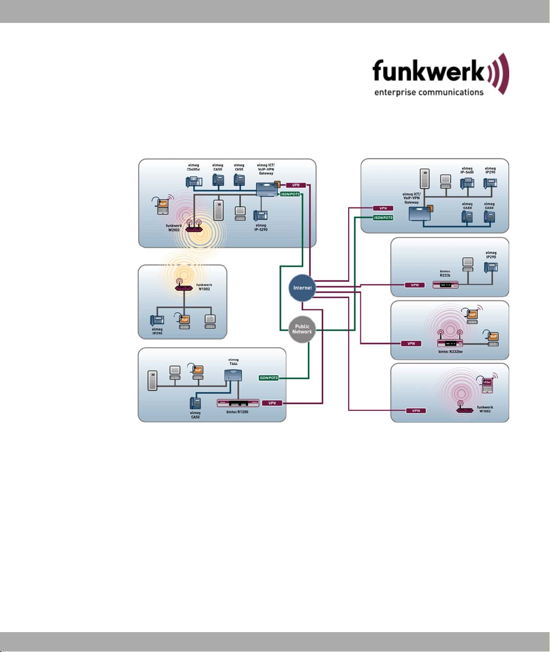
Possible Applications
To meet the different requirements relating to the various tasks, the access points have
one, two or three wireless modules and two, three or four antennas, depending on the
model, in order to optimise the range or illumination of the radio range even under difficult
conditions. The wireless module offers operation modes Client, Access Point and Bridge.
bintec W1002/W1002n/W2002/WIx040/WIx065 1
Page 14

1 Introduction Funkwerk Enterprise Communications GmbH
If a number of different applications are used, it is important to prioritise certain traffic flows.
The devices in the bintec Wx002 and bintec WI series therefore support WMM (wireless
multimedia). This enables voice or video data to be prioritised in order to ensure optimum
transmission quality for time-critical applications.
Your access point supports the latest WLAN technology and is designed for use particularly
in the professional environment. The devices in the robust WI series are specially optimised for use in difficult conditions in the industrial and outdoor sphere.
The WI series is available in two variants:
• Indoor Version with IP40 safety class (bintec WI1040, bintec WI2040 and bintec
WI3040)
• Outdoor version with IP65 safety class (bintec WI1065, bintec WI2065 and bintec
WI3065)
In addition to the radio standards 802.11b and 802.11g, the devices support 802.11a and
its European version 802.11h, so that data can also be transmitted in the 5 GHz frequency
range with data throughput of up to 54 mbps. This is required particularly for outdoor applications to achieve bridge solutions if other applications are already running in the 2.4
GHz frequency range.
bintec W1002n also supports 802.11n (Draft 2.0), which used MIMO technology (Multiple
Input Multiple Output) for data transmission that allows data transfer via WLAN over longer
distances or with higher data rates. With bandwidth 20 MHz or 40 MHz a gross data rate of
150 Mbps or 300 Mbps is achieved.
The products also support modern procedures such as Multi SSID and VLAN, with which
up to 16 virtual access points (8 SSIDs for bintec W1002n) can be mapped for each wireless module. These can be mutually protected and therefore ensure e.g. restricted guest
access for customers. Different safety levels and encryptions can be configured for each
SSID.
To ensure security is not neglected, the devices support security standards 802.1x and
802.11i (WPA, WPA2). The secure configuration is carried out over HTTPS or SSH.
Used as a bridge, the devices support Automatic Bridge Mode and are able to protect
bridge connection via TKIP and AES encryption.
WLAN Management
WLAN devices are designed for use with WiLMA. WiLMA, the WLAN management solution from Funkwerk, offers a software application in a client/server architecture that allows
you to centrally monitor, control and maintain all Funkwerk access points in medium and
large wireless LANs.
2 bintec W1002/W1002n/W2002/WIx040/WIx065
Page 15

Funkwerk Enterprise Communications GmbH
Chapter 2 About this guide
Area of validity
This document is valid for bintec devices with system software as of software version 7.8.2
or 7.8.3 ( bintec W1002n).
The guide, which you have in front of you, contains the following chapters:
User's Guide - Reference
Chapter Description
Introduction You see an overview of the device along with its possible ap-
About this guide We explain the various components of this manual and how to
Installation This contains instructions for how to set up and connect your
Basic configuration This chapter provides a step-by-step guide to the basic func-
Technical data
Access and configuration
System management
Physical interfaces
2 About this guide
plications and configuration options.
use it.
device.
tions on your device.
This section contains a description of all the device's technical
properties.
This includes explanations about the different access and configuration methods.
These chapters describe all configuration options of the Funkwerk Configuration Interface. The chapters are based on the
navigation structure.
LAN
Wireless LAN
Routing
WAN
VPN
Firewall
Local services
bintec W1002/W1002n/W2002/WIx040/WIx065 3
Page 16
2 About this guide Funkwerk Enterprise Communications GmbH
Chapter Description
Maintenance
External Reporting
Monitoring
Glossary
Index
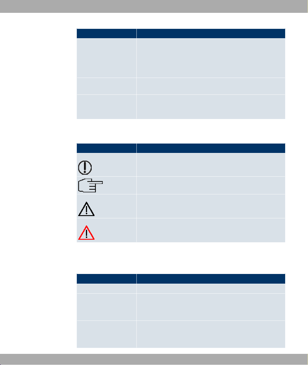
To help you locate information easily, this user's guide uses the following visual aids:
List of visual aids
Icon Use
The glossary contains a reference to the most important technical terms used in network technology.
The index lists all the key terms for operating the device and all
the configuration options and gives page numbers so they can
be found easily.
Indicates practical information.
Indicates general and important points.
Indicates a warning of risk level "Attention" (points out possible
dangers that may cause damage to property if not observed).
Indicates a warning of risk level "Warning" (points out possible
dangers that may cause physical injury or even death if not observed).
The following typographical elements are used to help you find and interpret the information in this user's guide:
Typographical elements
Typographical element Use
•
Menu->Submenu
File->Open
non-proportional, e.g.
ping 192.168.1.254
Indicates lists.
Indicates menus and sub-menus.
Indicates commands that you must enter as written.
4 bintec W1002/W1002n/W2002/WIx040/WIx065
Page 17

Funkwerk Enterprise Communications GmbH
Typographical element Use
2 About this guide
bold, e.g. Windows
Start menu
bold, e.g. biboAdmLo-
ginTable
italic, e.g. none Indicates values that you enter or that can be configured.
Online: blue and italic,
e.g.
www.funkwerk-ec.com
Indicates keys, key combinations and Windows terms.
Indicates fields.
Indicates hyperlinks.
bintec W1002/W1002n/W2002/WIx040/WIx065 5
Page 18
3 Installation Funkwerk Enterprise Communications GmbH
Chapter 3 Installation
Caution
Please read the safety notices carefully before installing and starting up your device.
These are supplied with the device.
Refer to chapter Technical data on page 26.
3.1 Setting Up and Connecting
Note
All you need for this are the cables and antennas supplied with the equipment.
The device can be fitted with various antenna systems. External, screw-on standard
antennas can be used (optional).
The access points of the bintec WI series can be mounted on a mast (indoor and outdoor version) or DIN rail (indoor version only). Optional theft protection is also available for the indoor and outdoor versions.
For the bintec WI series devices, a screw terminal bar is included as standard for
power supply.
Caution
The use of the wrong mains adapter may damage your device. Only use the mains adaptor supplied (only for bintec W1002, bintec W1002n and bintec W2002). If you require foreign adapters/mains units, please contact our funkwerk service.
6 bintec W1002/W1002n/W2002/WIx040/WIx065
Page 19
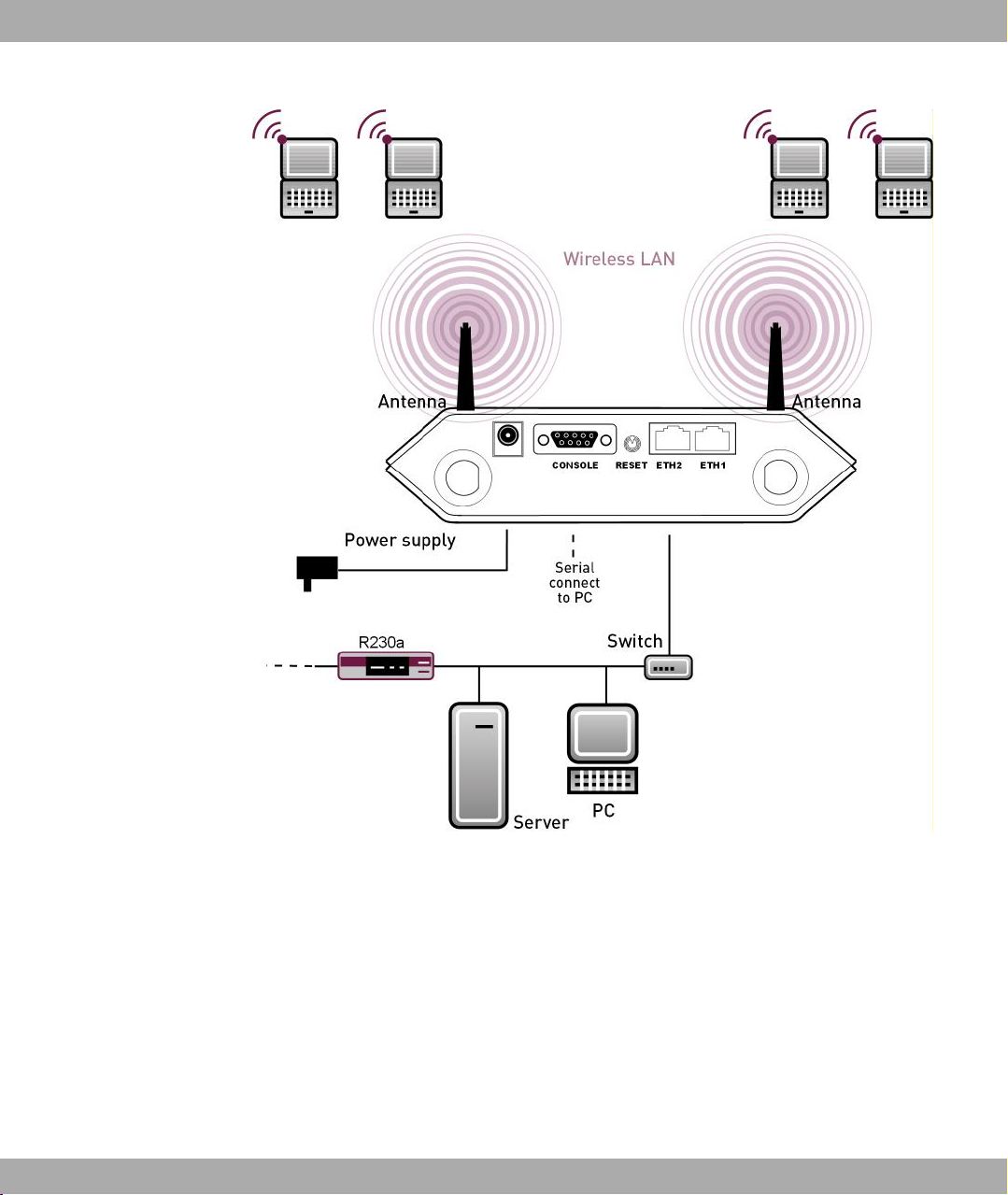
Funkwerk Enterprise Communications GmbH
3 Installation
Fig. 2: Connection options bintec W1002, bintec W1002n and bintec W2002
bintec W1002/W1002n/W2002/WIx040/WIx065 7
Page 20
3 Installation Funkwerk Enterprise Communications GmbH
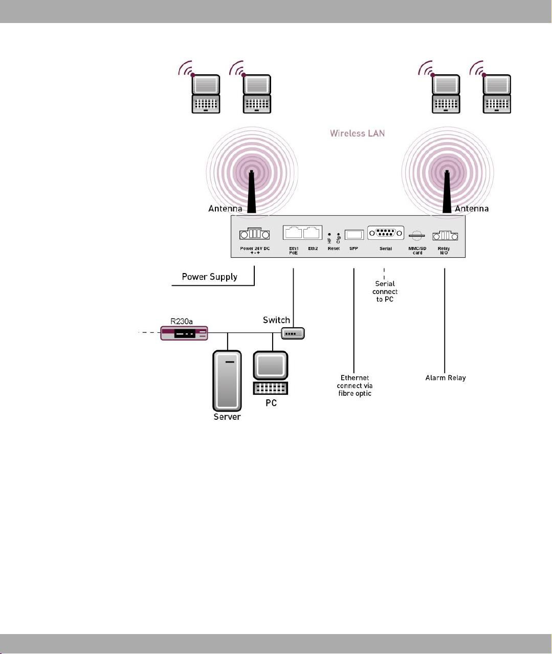
Fig. 3: Connection options bintec WIx040 and bintec WIx060.
When setting up and connecting, carry out the steps in the following sequence (refer to the
connection diagrams for the individual devices in chapter Technical data on page 26):
(1) Antennas
Screw the external standard antennas supplied on to the connections provided for
this purpose.
Put the antennas in the required position before tightening the screw nut. Once the
screw nut has been tightened, it may not be possible to rotate the radiator any more.
If two antennas are connected to the device, these must be installed at least 6 cm
and preferably 12 cm apart so that antenna diversity can be used.
In highly reflective environments, it may make sense to maintain an angle of 90° in
the direction of the antennas. For this, arrange the antennas in a V shape.
(2) Installation
The access points can be fitted to the wall using brackets on the housing or can
8 bintec W1002/W1002n/W2002/WIx040/WIx065
Page 21
Funkwerk Enterprise Communications GmbH
used as a table-top device.
Wall mounting
To attach the device to the wall, use the brackets on the back of the housing. Optional wall mounting with theft protection is available.
Note
Before drilling, make sure that there are no building installations where you are drilling.
If gas, electricity, water or waste water lines are damaged, you may endanger your life
or damage property.
• Screw the mount to the wall with the 2 screws.
• Hang the device in the mount with the screw nut but do not tighten it. Make sure the
device connections are accessible.
• Protect the device against theft with the lock supplied.
3 Installation
Fig. 4: Wall mounting straps for bintec W1002, bintec W1002n and bintec W2002
bintec W1002/W1002n/W2002/WIx040/WIx065 9
Page 22
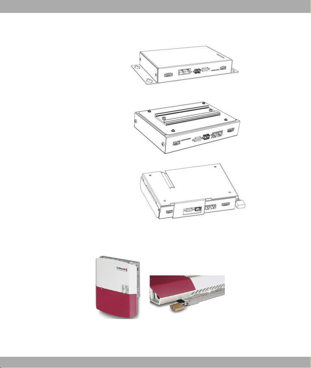
3 Installation Funkwerk Enterprise Communications GmbH
Fig. 5: Wall mounting of the bintec WIx040 (standard design, DIN rail or theft protection optional)
Fig. 6: Wall mounting of the bintec Wx065 (standard design and with theft protection)
Use as a table-top device
The access point can also be used as a table-top device. For this option, use the
10 bintec W1002/W1002n/W2002/WIx040/WIx065
Page 23

Funkwerk Enterprise Communications GmbH
four self-adhesive feet on the bottom of the device. Place your device on a solid,
level base.
(3) LAN
For the standard configuration of your device via Ethernet, connect port ETH1 or
ETH2 of your device to your LAN using the Ethernet cable supplied. The device
automatically detects whether it is connected to a switch or directly to a PC.
Use just one of the ports ETH1 and ETH2, the second port is used to cascade a
number of devices. If you use both Ethernet connections on the same switch, loops
may be formed.
The standard patch cable (RJ45-RJ45) is symmetrical. It is therefore not possible to
mix up the cable ends.
(4) Power connection
Connect the device to a mains socket using the mains adaptor supplied.
Use the power cord supplied (or the screw strip terminal in the case of the WI
series) and insert it in the appropriate socket on your device. Now plug the power
cord into a power socket (100–240 V). The status LEDs signal that your device is
correctly connected to the power supply.
Note
3 Installation
To limit power in the event of a fault, the 24-V DC supply for bintec WIx040 and
bintec WIx065 must be protected with an externally fitted 2-A fuse.
Note
If the bintec WIx065 is installed outdoors, the lines laid outside the building are to be
categorised as TNV1 electric circuits in accordance with EN60950, as their SELV level
can also be overridden by transient overvoltage (e.g. during storms) during operation
in line with the regulations. When wiring the connections, it is therefore necessary to
make sure that protective measures against overvoltage are carried out where the
cable enters the building, to ensure that the limit values of a SELV electric circuit are
maintained in the building.
You can set up further connections as required:
• Setting up a serial connection: For alternative configuration possibilities, connect the seri-
al interface of your PC (COM1 or COM2) to the serial interface of the gateway (console).
However, configuration via the serial interface is not provided by default.
The device is now ready for configuration.
bintec W1002/W1002n/W2002/WIx040/WIx065 11
Page 24

3 Installation Funkwerk Enterprise Communications GmbH
3.2 Support information
If you have any questions on your new product or would like more information, you can
reach the Support Centre of Funkwerk Enterprise Communications GmbH under the following call number or via the E-mail Hotline:
+49 911 9673 1550
hotline@funkwerk-ec.com
For detailed information on our support services, contact www.funkwerk-ec.com.
12 bintec W1002/W1002n/W2002/WIx040/WIx065
Page 25

Funkwerk Enterprise Communications GmbH
Chapter 4 Basic configuration
You can use the ComPoint Manager (IP address assignment) and the Funkwerk Configuration Interface (other configuration steps) for the basic configuration of your device.
The basic configuration is explained below step-by-step. A detailed online help system
gives you extra support.
This user’s guide assumes you have the following basic knowledge:
• Basic knowledge of network structure
• Knowledge of basic network terminology, such as server, client and IP address
• Basic knowledge of using Microsoft Windows operating systems
The CD also supplied includes all the tools that you need for the configuration and management of your device.
You can find other useful applications on the Internet at www.funkwerk-ec.com.
4 Basic configuration
4.1 Presettings
4.1.1 Preconfigured data
You have three ways of accessing your device in your network to perform configuration
tasks:
(a) Dynamic IP address
In ex works state, your device is set to DHCP client mode, which means that when it is
connected to the network, it is automatically assigned an IP address if a DHCP server
is run. You can then access your device for configuration purposes using the IP address assigned by the DHCP server. For information on determining the dynamically
assigned IP address, please see your DHCP server documentation.
(b) Fallback IP address
If you do not run a DHCP server, you can connect your device directly to your configuration PC and then reach it using the following, predefined fallback IP configuration:
• IP Address: 192.168.0.252
• Netmask: 255.255.255.0
Make sure that the PC from which the configuration is performed has a suitable IP
bintec W1002/W1002n/W2002/WIx040/WIx065 13
Page 26

4 Basic configuration Funkwerk Enterprise Communications GmbH
configuration (see Configuring a PC on page 17).
(c) Assigning a fixed IP address
You can use the ComPoint Manager to assign the required IP address to your device.
Note
Please note:
If your device has obtained an IP address dynamically from a DHCP server operated
in your network for the basic configuration, the fallback IP address 192.168.0.252 is
deleted automatically and your device will no longer function over this address.
However, if you have set up a connection to the device over the fallback IP address
192.168.0.252 or have assigned an IP address with the ComPoint Manager in the basic configuration, you will only be able to access your device over this IP address. The
device will no longer obtain an IP configuration dynamically over DHCP.
Use the following access data to configure your device in ex works state:
• User Name: admin
• Password: funkwerk
Note
All bintec devices are delivered with the same username and password. As long as
the password remains unchanged, they are therefore not protected against unauthorized use. Make sure you change the passwords to prevent unauthorized access to
your device! (see Modify system password on page 20).
4.1.2 Software update
Your device contains the version of the system software available at the time of production.
More recent versions may have since been released. You can easily perform an update
with the Funkwerk Configuration Interface using the Maintenance->Software & Config-
uration menu. For a description of the procedure, see Software Update on page 23.
4.2 System requirements
For configuration, your PC must meet the following system requirements:
14 bintec W1002/W1002n/W2002/WIx040/WIx065
Page 27

Funkwerk Enterprise Communications GmbH
• Microsoft Windows operating system Windows 2000 or higher
• Internet Explorer 6 or 7, Mozilla Firefox Version 1.2 or higher
• Installed network card (Ethernet)
• CD ROM drive
• Installed TCP/IP protocol
• High colour display (more than 256 colours) for correct representation of the graphics
4.3 Preparations
To prepare for configuration, you need to:
• Obtain the data required for the basic configuration.
• Check whether the PC from which you want to perform the configuration meets the necessary requirements.
4.3.1 Gathering data
4 Basic configuration
The main data for the basic configuration can be gathered quickly, as no information is required that needs in-depth network knowledge. If applicable, you can use the example values.
Before you start the configuration, you should gather the data for the following purposes:
• IP configuration (obligatory if your device is in the ex works state)
• Optional: Configuration of a wireless network connection in Access Point mode
• Optional: Configuration of client links in Client Links mode
• Optional: Configuration of bridge links in Bridge mode.
The following table shows examples of possible values for the necessary data. You can
enter your personal data in the "Your values" column, so that you can refer to these values
later when needed.
If you configure a new network, you can use the given example values for IP addresses
and netmasks. In cases of doubt, ask your system administrator.
Basic configuration
For a basic configuration of your gateway, you need information that relates to your network environment:
IP configuration of the access point
bintec W1002/W1002n/W2002/WIx040/WIx065 15
Page 28

4 Basic configuration Funkwerk Enterprise Communications GmbH
Access data Example value Your values
IP address of your access point 192.168.0.252
Netmask of your access point 255.255.255.0
Access Point mode
If you run your device in Access Point mode, you can set up the required wireless networks. To do this, you need the following data:
Configuration of a wireless network
Access data Example value Your values
Network Name (SSID) Funkwerk-ec
Security Mode WPA-PSK
Preshared Key supersecret
Access Client mode
If you run your device in Access Client mode, you can set up the required client links. To do
this, you need the following data:
IP configuration of the access client
Access data Example value Your values
Network Name (SSID) Funkwerk-ec
Security Mode WPA-PSK
Preshared Key supersecret
Bridge mode
If you run your device in Bridge mode, you can either configure connections to other
bridges manually or use the bridge link autoconfiguration function. For the manual configuration of a bridge link, you need the following data:
Configuration of a bridge link
Access data Example value Your values
Preshared Key bridgesecret
MAC address of remote bridge 00:a0:f9:5a:42:53
To use the bridge link autoconfiguration function, proceed as described in the Automatic
Configuration of a Bridge Link workshop and read the Wireless LAN chapter of the
user's guide under WLAN1 -> Bridge Links -> Add.
16 bintec W1002/W1002n/W2002/WIx040/WIx065
Page 29

Funkwerk Enterprise Communications GmbH
4.3.2 Configuring a PC
In order to reach your device via the network and to be able to carry out configuration, the
PC used for the configuration has to satisfy some prerequisites.
• Make sure that the TCP/IP protocol is installed on the PC.
• Select the suitable IP configuration for your configuration PC.
The PC via which you want to configure the IP address for your device must be in the
same network as your device.
Checking the Windows TCP/IP protocol
Proceed as follows to check whether you have installed the protocol:
(1) Click the Windows Start button and then Settings -> Network and Dial-up Connec-
tions (Windows 2000) orControl Panel->Network and Internet Connections
(Windows XP).
(2) Click on LAN Connection.
(3) Click on Properties in the status window.
(4) Look for the Internet Protocol (TCP/IP) entry in the list of network components.
4 Basic configuration
Installing the Windows TCP/IP protocol
If you cannot find the Internet Protocol (TCP/IP) entry, install the TCP/IP protocol as fol-
lows:
(1) First click Properties, then Install in the status window of the LAN Connection.
(2) Select the Protocol entry.
(3) Click Add.
(4) Select Internet Protocol (TCP/IP) and click on OK.
(5) Follow the on-screen instructions and restart your PC when you have finished.
Allocating PC IP address
Allocate an IP address to your PC as follows:
(1) Select Internet Protocol (TCP/IP) and click on Properties.
(2) Choose Use following IP address and enter a suitable IP address, the matching net-
mask, your default gateway and your preferred DNS server.
If you run a DHCP server in your network, you can apply the default Windows setting Ob-
tain IP address automatically and Obtain DNS server address automatically.
bintec W1002/W1002n/W2002/WIx040/WIx065 17
Page 30
4 Basic configuration Funkwerk Enterprise Communications GmbH
Your PC should now meet all the prerequisites for the configuration of your device.
4.4 IP configuration
In the ex works state, your device is configured in DHCP Client mode and therefore dynamically receives an IP address if you run a DHCP server in your network. If this is not the
case, connect your device directly to the configuration PC and use the fallback IP address
192.168.0.252.
Alternatively, you can assign your device the required fixed IP address by using the Com-
Point Manager.
To do this, install the program from the CD provided on your configuration PC.
Proceed as follows:
(a) Place the CD provided in the CD-ROM drive of your configuration PC. The installation
wizard should start automatically. If it does not, open the following file on the CD using
your file browser: starter.exe.
(b) Follow the instructions in the installation wizard.
Then carry out the following steps to configure an IP address for your device:
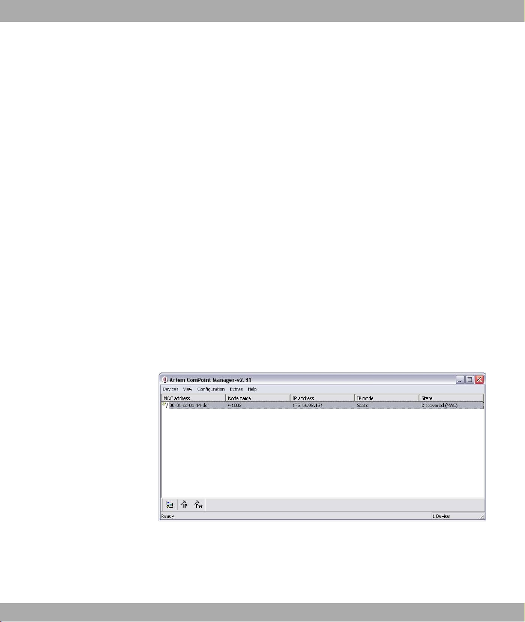
(1) Start the ComPoint Manager from the Windows Start menu: Start -> Programs ->
funkwerk -> ComPoint Manager.
The following dialog box appears:
Fig. 7: ComPoint Manager initial screen
The ComPoint Manager detects the devices installed in the network.
(2) In the list, double click the MAC address of the device you want to configure.
If you do not know the MAC address of the device: A label containing the most important device data, including the MAC address, is attached to the device.
18 bintec W1002/W1002n/W2002/WIx040/WIx065
Page 31

Funkwerk Enterprise Communications GmbH
The following dialog box appears:
Fig. 8: IP address assignment with the ComPoint Manager
(3) Enter the network parameters (Device name, IP address, subnet mask and Stand-
ard gateway) and click on OK.
4 Basic configuration
Note
The maximum length of the Device name parameter is 32 characters.
The Device name parameter may contain only the letters "a"-"z", "A"-"Z", the digits
"0"-"9", dash "-" and dot "." to avoid errors by other systems during interpretation of the
Device name. The first character must be a letter, and the last character cannot be a
dot "." or dash "-". A single character is not permitted as a name.
Your device can now be reached over the Ethernet with its IP address using a Web
browser and can now be configured.
Note
The other functions of the ComPoint Manager are not available.
Calling up the Funkwerk Configuration Interface
bintec W1002/W1002n/W2002/WIx040/WIx065 19
Page 32

4 Basic configuration Funkwerk Enterprise Communications GmbH
Fig. 9: Funkwerk Configuration Interface Login
Start the configuration interface as follows:
(a) Enter the IP address of your device in the address line of your Web browser.
With DHCP server:
• the IP address that the DHCP server assigned to your device
Without DHCP server:
• With direct connection to the configuration PC: the fallback IP address
192.168.0.252
• The fixed IP address assigned via the ComPoint Manager
Press the Enter (Return) key.
(b) Enter admin in the User field and funkwerk in the Password field.
4.5 Modify system password
All bintec devices are delivered with the same username and password. As long as the
password remains unchanged, they are therefore not protected against unauthorized use.
Make sure you change the passwords to prevent unauthorized access to your device!
Proceed as follows:
(a) Go to System Management -> Global Settings-> Passwords
(b) Enter a new password under System Admin Password.
(c) Enter the new password again under Confirm Admin Password.
20 bintec W1002/W1002n/W2002/WIx040/WIx065
Page 33

Funkwerk Enterprise Communications GmbH
(d) Click OK.
(e) Save the configuration by clicking on the Save Configuration button above the menu
navigation.
Note the following rules on password use:
• The password must not be easy to guess. Names, car registration numbers, dates of
birth, etc. should not be chosen as passwords.
• The password should contain at least one character that is not a letter (special character
or number).
• The password should be at least 8 characters long.
• Change your password regularly, e.g. every 90 days.
4.6 Setting up a wireless network
If you run your device in Access Point mode, you must set up a wireless network.
Proceed as follows:
(1) Go to Wireless LAN -> WLANx -> Radio Settings -> .
4 Basic configuration
(2) In Operating Mode, select Access Point.
(3) Leave the default settings in all other fields.
(4) Click on OK.
(5) Go to Wireless LAN -> WLANx -> Virtual Service Sets -> .
(6) In Network name (SSID) enter, for example, Funkwerk-ec.
(7) Under Security Mode, select WPA-PSK.
(8) In Preshared Key enter, for example, supersecret.
(9) Leave the default settings for all other fields.
(10) Click on OK.
4.7 Setting up a bridge link
If you run your device in Bridge mode, you must set up a bridge link.
Bridge link autoconfiguration
(1) Go to Wireless LAN -> WLANx -> Radio Settings -> .
(2) In Operation Mode, select Bridge.
(3) Leave the default settings in all other fields.
bintec W1002/W1002n/W2002/WIx040/WIx065 21
Page 34

4 Basic configuration Funkwerk Enterprise Communications GmbH
(4) Click on OK.
(5) Go to Wireless LAN -> WLANx -> Bridge Links -> New.
(6) In Preshared Key enter, for example, bridgesecret.
(7) Leave the default settings in all other fields.
(8) Click on OK.
(9) Configure a bridge link on the remote device in the same way.
(10) For your local device, click the icon in the list in Wireless LAN -> WLANx ->
Bridge Links .
(11) In the menu that opens, Wireless LAN -> WLANx -> Bridge-Links -> under Ac-
tion, click the [Scan] link.
(12) After the scan, the results are listed. For the desired list entry, click on the [Connect]
link.
To use the bridge link autoconfiguration function, proceed as described in the Automatic
Configuration of a Bridge Link workshop and read the Wireless LAN chapter of the
user's guide under WLAN1 -> Bridge Links -> Add.
Manual configuration
(1) Go to Wireless LAN -> WLANx -> Radio Settings -> Edit.
(2) In Operation Mode, select Bridge.
(3) Leave the default settings in all other fields.
(4) Click on OK.
(5) Go to Wireless LAN -> WLANx -> Bridge Links -> .
(6) In Preshared Key enter, for example, bridgesecret.
(7) For Remote MAC address, enter the MAC address of the bridge to which your bridge
is to set up a connection, e.g. 00:a0:f9:5a:42:53.
(8) Leave the default settings in all other fields.
(9) Click on OK.
(10) Configure a bridge link on the remote device in the same way.
Your device is ready for operation when you have completed the configuration.
The configuration of the device and its integration into your network are now completed.
22 bintec W1002/W1002n/W2002/WIx040/WIx065
Page 35

Funkwerk Enterprise Communications GmbH
4.8 Software Update
The range of functions of bintec devices is continuously being extended. These extensions
are made available to you by Funkwerk Enterprise Communications GmbH free of charge.
Checking for new software versions and the installation of updates can be carried out easily with the Funkwerk Configuration Interface. An existing internet connection is needed
for an automatic update.
Proceed as follows:
(1) In the Maintenance ->menu, select Software & configuration.
(2) Under Action, select Update System Software and, under Source, Latest
Software from Funkwerk Server.
(3) Then click GO.
4 Basic configuration
The device will now connect to the Funkwerk Enterprise Communications GmbH download
server and check whether an updated version of the system software is available. If so,
your device will be updated automatically. When installation of the new software is complete, you will be invited to restart the device.
Caution
Once you have clicked on GO , the update cannot be cancelled/interrupted. If an error
occurs during the update, do not re-start the device and contact support.
bintec W1002/W1002n/W2002/WIx040/WIx065 23
Page 36

5 Reset Funkwerk Enterprise Communications GmbH
Chapter 5 Reset
If the configuration is incorrect or if your device cannot be accessed, you can reset the
device to the ex works standard settings using the Reset button on the bottom of the
device.
Practically al existing configuration data will then be ignored, only the current user passwords are retained. Configurations stored in the device are not deleted and can, if required,
be reloaded when the device is rebooted.
Proceed as follows:
(1) Switch off your device.
(2) Press the Reset button on your device.
(3) Keep the Reset button on your device pressed down and switch the device back on.
(4) Look at the LEDs:
- The Power and Status LEDs come on first.
- The Ethernet LEDs ( 1 to 4 ) for the ports connected to the Ethernet then flash.
- The device runs through the boot sequence.
- After the Status LED has flashed five times, release the Reset button.
On devices of the WI series, the red Failure LED comes on first. Hold in the Reset button until the red LED goes out and the green Status LED starts to flash.
Proceed as follows if you also want to reset all the user passwords to the ex works state
and delete stored configurations when resetting the device:
(1) Set up a serial connection to your device. Reboot your device and monitor the boot
sequence. Start the BOOTmonitor and choose (4) Delete Configuration and following the instructions.
or
(2) Set up a serial connection to your device. First carry out the reset procedure de-
scribed and enter erase bootconfig as Login at the login prompt in the command
line. Leave the password empty and press the Return key. The device runs through
the boot sequence again.
You can now configure your device again as described from Basic configuration on page
13.
24 bintec W1002/W1002n/W2002/WIx040/WIx065
Page 37

Funkwerk Enterprise Communications GmbH
Note
If you delete the boot configuration using the Funkwerk Configuration Interface, all
passwords will also be reset and the current boot configuration deleted. The next time,
the device will boot with the standard ex works settings.
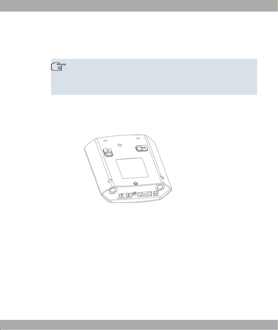
On devices of the WI series, there is a further reset button - the HW reset. After pressing
briefly once, the device reboots.
5 Reset
Fig. 10: Underside of the bintec WIx040 with the HW and Cfg reset buttons
bintec W1002/W1002n/W2002/WIx040/WIx065 25
Page 38

6 Technical data Funkwerk Enterprise Communications GmbH
Chapter 6 Technical data
In this chapter, all hardware characteristics of the devices bintec W1002, W1002n, W2002,
WI1040, WI2040, WI3040, WI1065, WI2065 and WI3065 are summarised.
6.1 bintec W1002, bintec W1002n and bintec W2002
6.1.1 Scope of supply
Your device is supplied with the following parts:
• Cable sets/mains unit:
- Ethernet cable (RJ-45, STP)
- Plug-in power pack (12 V/230 V)
• Self-adhesive feet to allow the device to be used as a desktop device
• Installation material
• Antennas:
- 2 external standard antennas to be screwed on (for bintec W1002)
- 3 external standard antennas to be screwed on (for bintec W1002n)
- 4 external standard antennas to be screwed on (for bintec W2002)
• CD
• Documentation:
- User's Guide (on CD)
- Quick Install Guide (printed)
- R&TTE Compliance Information (printed)
- Safety notices (printed)
6.1.2 General Product Features
The general product features cover performance features and the technical prerequisites
for installation and operation of your device.
26 bintec W1002/W1002n/W2002/WIx040/WIx065
Page 39

Funkwerk Enterprise Communications GmbH
The features are summarised in the following table:
General Product Features
Property Value
Variants:
bintec W1002 One internal wireless module, 2 external antennas
bintec W1002n One internal wireless module, 3 external antennas
bintec W2002 Two internal wireless modules, 4 external anten-
Dimensions and weights:
6 Technical data
nas
Equipment dimensions without cable
(W x L x H)
Weight approx. 430 g
LEDs bintec W1002 and bintec W2002:
Power consumption of the device 5-10 Watt, depending on extensions
Voltage supply External switched-mode power supply 12 V DC,
Environmental requirements:
Storage temperature -10° to +70 °C
Operating temperature 0° to 40 °C
Relative atmospheric humidity 10 % to 95 % (non-condensing)
Room classification Only use in dry rooms.
Available interfaces:
Serial interface V.24 Permanently installed, supports Baud rates: 1200,
Ethernet IEEE 802.3 LAN (2-port Permanently installed (twisted pair only), 10/100
163 mm x 168 mm x 50 mm
5 (1x Status, 2x WLAN, 2x Ethernet)
bintec W1002n:
4 (1x Status, 1x WLAN, 2x Ethernet)
1.25 A
PoE on Ethernet 1 Class 0 (insulated) with max.
two WLAN modules
2400, 4800, 9600, 19200, 38400, 57600, 115200
Baud
bintec W1002/W1002n/W2002/WIx040/WIx065 27
Page 40

6 Technical data Funkwerk Enterprise Communications GmbH
Property Value
switch) mbps, autosensing, MDIX
Available sockets:
Serial interface V.24 9-pin Sub-D connector
Ethernet interface RJ45 socket
Antennas:
Antenna connection RTNC socket
Transmit Power max. 100 mW (20 dBm) EIRP
Receiver sensitivity bintec
W1002/bintec W2002
In the 5 GHz frequency band
PER 10 %
6 mbps -90 dBm, 9 mbps -88 dBm,
12 mbps -86 dBm, 18 mbps -84 dBm,
24 mbps -79 dBm, 36 mbps -76 dBm,
48 mbps -71 dBm, 54 mbps -69 dBm
In the 2.4 GHz frequency band
PER 8 %:
1 mbps -98 dBm, 2 mbps -93 dBm;
5.5 mbps -92 dBm, 11 mbps -88 dBm;
PER 10 %: 6 mbps -92 dBm, 9 mbps -90 dBm;
12 mbps -88 dBm, 18 mbps -86 dBm;
24 mbps -82 dBm, 36 mbps -78 dBm;
48 mbps -73 dBm, 54 mbps -71 dBm
Receiver sensitivity bintec W1002n 2.4 GHz 802.11b/g:
1 mbps -91 dBm; 2 mbps -90 dBm; 5.5 mbps -89
dBm; 11 mbps -88 dBm; 6 mbps -90 dBm; 9 mbps
-89 dBm; 12 mbps -88 dBm; 18 mbps -86 dBm; 24
mbps -83 dBm; 36 mbps -80 dBm; 48 mbps -76
dBm; 54 mbps -74 dBm
2.4 GHz 802.11n 20MHz:
28 bintec W1002/W1002n/W2002/WIx040/WIx065
Page 41

Funkwerk Enterprise Communications GmbH
Property Value
6 Technical data
MSC0 -89 dBm; MSC1 -87 dBm; MCS2 -85 dBm;
MCS3 -82 dBm; MCS4 -79 dBm; MSC5 -75 dBm;
MCS6 -73 dBm; MCS7 -70 dBm; MCS8 -83 dBm;
MCS9 -84 dBm; MCS10 -81 dBm; MCS11 -79
dBm; MCS12 -80 dBm; MCS13 -72 dBm; MCS14 68 dBm; MCS15 -67 dBm
2.4 GHz 802.11n 40 MHz:
MSC0 -87 dBm; MSC1 -84 dBm; MCS2 -82 dBm;
MCS3 -79 dBm; MCS4 -75 dBm; MSC5 -71 dBm;
MCS6 -69 dBm; MCS7 -67 dBm; MCS8 -86 dBm;
MCS9 -83 dBm; MCS10 -79 dBm; MCS11 -77
dBm; MCS12 -74 dBm; MCS13 -69 dBm; MCS14 67 dBm; MCS15 -65 dBm
5 GHz 802.11a/h:
6 mbps -88 dBm; 9 mbps -87 dBm; 12 mbps -86
dBm; 18 mbps -84 dBm; 24 mbps -82 dBm; 36
mbps -78 dBm; 48 mbps -74 dBm; 54 mbps -73
dBm;
5 GHz 802.11n 20 MHz:
MSC0 -88 dBm; MSC1 -85 dBm; MCS2 -83 dBm;
MCS3 -81 dBm; MCS4 -78 dBm; MSC5 -74 dBm;
MCS6 -72 dBm; MCS7 -70 dBm; MCS8 -88 dBm;
MCS9 -85 dBm; MCS10 -83 dBm; MCS11 -80
dBm; MCS12 -77 dBm; MCS13 -72 dBm; MCS14 70 dBm; MCS15 -68 dBm
2.4 GHz 802.11n 40 MHz:
MSC0 -84 dBm; MSC1 -82 dBm; MCS2 -79 dBm;
MCS3 -77 dBm; MCS4 -74 dBm; MSC5 -69 dBm;
MCS6 -67 dBm; MCS7 -66 dBm; MCS8 -83 dBm;
MCS9 -82 dBm; MCS10 -79 dBm; MCS11 -76
dBm; MCS12 -72 dBm; MCS13 -68 dBm; MCS14 66 dBm; MCS15 -64 dBm
Modulation Modulation IEEE802.11 standards: a,h (5 GHz) g,b
(2.4 GHz)
Modulation types: 11, 5.5, 2 and 1 mbps (DSSS)
bintec W1002/W1002n/W2002/WIx040/WIx065 29
Page 42

6 Technical data Funkwerk Enterprise Communications GmbH
Property Value
2.4 GHz;
54, 48, 36, 24, 18, 12, 9 and 6 mbps (OFDM) 2.4
and 5 GHz
Channels IEEE802.11b/g: 13 channels (Europe)
IEEE802.11a/h: 19 channels (Europe)
Standards IEEE 802.11a,b,g,d,h,i
IEEE 802.11n (Mimo 2x3) only bintec W1002n
IEEE 802.3
IEEE 802.3af
IEEE 802.1q (VLAN Tagging)
Frequency bands 2.4 GHz Indoor/Outdoor (2412-2484 MHz)
5 GHz Indoor (5150-5350 MHz)
5 GHz Outdoor (5470-5725 MHz)
5 GHz BFWA (5755-5875 MHz) only Germany,
compulsory registration only for bintec W1002n
Standards & Guidelines R&TTE Directive 1999/5/EC
EN 60950 (IEC60950); EN 300 328-1/2; ETSI EN
301 489-1/17; EN 6060-1-2 (medicine)
Buttons A monitor button
Security features WEP64 (40 bit key), WEP128 (104 bit key), WPA
Personal, WPA Enterprise, WPA2 Personal, WPA2
Enterprise
Access Control List, Network Name Broadcast can
be deactivated
WEP key length (bit) 40 (64) or 104 (128)
Software supplied ComPoint Manager
BOSS operating system
30 bintec W1002/W1002n/W2002/WIx040/WIx065
Page 43

Funkwerk Enterprise Communications GmbH
Property Value
Printed documentation supplied Quick Reference
Online documentation User's Guide
6.1.3 LEDs
The five LEDs show the radio status, radio activity, Ethernet activity and LED states of your
device. The LED states are indicated by combinations of the LEDs which are explained in
detail in this chapter.
They are arranged as follows:
6 Technical data
Safety notices
R&TTE Compliance Information
Fig. 11: LEDs of bintec W1002 and bintec W2002
Fig. 12: LEDs of bintec W1002n
In operation mode, the LEDs display the following status information for your device:
LED status display
LED State Information
State off The power supply is not connected. If
other LEDs are on, also Error.
on (static) Error
on (flashing) Ready
WLAN (1/2) on (flashing slowly) Free
on (static) At least one client is registered
bintec W1002/W1002n/W2002/WIx040/WIx065 31
Page 44

6 Technical data Funkwerk Enterprise Communications GmbH
LED State Information
on (flickering) At least one client is registered and
there is data traffic
on (flashing fast) BLD (Broken Link Detection) active
on (flashing fast) 5 GHz scan active
ETH 1/2 off No cable or no Ethernet link
on Cable plugged in and link
on (flickering) Cable plugged in and link with data
traffic
During the boot operation, all LEDs are on (1x red/green status and 4x green). This means
the monitor has been started and firmware is being loaded.
6.1.4 Connections
All the connections are located on the underside of the device. On bintec W1002n the third
antenna connection is located on the underside of the device. On bintec W2002 the third
and fourth antenna connections are located on the underside of the device. bintec W1002
and bintec W2002 have two Ethernet connections and one serial interface.
The connections are arranged as follows:
Fig. 13: bintec W1002 underside
32 bintec W1002/W1002n/W2002/WIx040/WIx065
Page 45

Funkwerk Enterprise Communications GmbH
Fig. 14: bintec W2002 underside
bintec W1002, bintec W2002 underside
1 POWER Socket for plug-in power pack
2 CONSOLE Serial Interface
3 RESET Reset button
4 ETH1 / ETH2 10/100 Base-T Ethernet interface
5 bintec W2002:
ANT1 AUX/ANT2
AUX
6 Technical data
Connections for screwing on the external antennas
bintec W1002:
ANT1 AUX/ANT2
Main
bintec W2002:
ANT1 Main/ANT2
Main
Fig. 15: bintec W1002n underside
bintec W1002n underside
1 POWER Socket for plug-in power pack
2 CONSOLE Serial Interface
Top (Fig.)
Connections for screwing on the external antennas
bintec W1002/W1002n/W2002/WIx040/WIx065 33
Page 46

6 Technical data Funkwerk Enterprise Communications GmbH
3 RESET Reset button
4 ETH1/PoE and
ETH2
5 ANT3 Connections for screwing on the external antennas
ANT1/ANT2 Top (Fig.)
10/100 Base-T Ethernet interface
ANT3 = RX3
Connections for screwing on the external antennas
ANT1 = TX/RX1 (Connection of first directional antenna)
ANT2 = TX/RX2 (Connection of second option directional antenna)
6.1.5 Pin Assignments
6.1.5.1 Ethernet interface
Your device has two Ethernet interfaces. These are used to connect individual PCs or other
switches.
The connection is made via an RJ45 socket.
Fig. 16: Ethernet 10/100 Base-T interface (RJ45 socket)
The pin assignment for the Ethernet 10/100 Base-T interface (RJ45 socket) is as follows:
RJ45 socket for LAN connection
Pin Function Eth1 - PoE Function Eth 2
1 TD +/Power TD +
2 TD -/Power TD -
3 RD +/Power RD +
4 Power Not used
34 bintec W1002/W1002n/W2002/WIx040/WIx065
Page 47

Funkwerk Enterprise Communications GmbH
Pin Function Eth1 - PoE Function Eth 2
5 Power Not used
6 RD -/Power RD -
7 Power Not used
8 Power Not used
The Ethernet 10/100 BASE-T interface does not have an Auto-MDI-X function.
6.1.5.2 Serial Interface
Your device has a Serial interface for connection to a console. This supports Baud rates
from 1200 to 115200 Bps.
The interface is designed as a 9-pin SUB-D socket.
Fig. 17: 9-pin Sub-D connector
6 Technical data
The pin assignment is as follows:
Pin assignment of the Sub-D port
Pin bintec W1002/bintec W2002
function
1 CD Not used
2 RxD RxD
3 TxD TxD
4 DTR Not used
5 GND GND
6 DSR DSR
7 RTS RTS
8 CTS CTS
9 RI Not used
bintec W1002n function
6.1.6 Frequencies and channels
Different certification regulations apply around the world. ETSI standards generally apply
(predominantly used in Europe). For operation in Europe, please read the notes in the
R&TTE Compliance Information.
bintec W1002/W1002n/W2002/WIx040/WIx065 35
Page 48

6 Technical data Funkwerk Enterprise Communications GmbH
6.2 bintec WI1040, WI2040 and WI3040
6.2.1 Scope of supply
Your device is supplied with the following parts:
• Cable sets:
- Serial cable (D-SUB9)
- Ethernet cable (RJ-45, STP)
• Self-adhesive feet to allow the device to be used as a desktop device
• Blind stops for SFP
• Installation material
- SD slot cover with screws
- 3-pole screw terminal bar for the power supply
- 2-pole screw terminal bar for relay
- Mounting bracket for wall mounting
• Antennas:
- 2 external standard antennas to be screwed on (for bintec WI1040)
- 4 external standard antennas to be screwed on (for bintec WI 2040 and WI 3040)
• CD
• Documentation:
- User's Guide (on CD)
- Quick Install Guide (printed)
- R&TTE Compliance Information (printed)
- Safety notices (printed)
36 bintec W1002/W1002n/W2002/WIx040/WIx065
Page 49

Funkwerk Enterprise Communications GmbH
6.2.2 General Product Features
To ensure safe operation, the WI series devices have a connection to earth. The minimum
cross-section of the earth lead should be 1.5 mm². The distance between the device and
the connection to earth should be as short as possible. For the bintec WIx065 devices, the
connection to earth is under the cover.
Fig. 18: Connection to earth bintec Wx040
The general product features cover performance features and the technical prerequisites
for installation and operation of your device.
6 Technical data
The features are summarised in the following table:
General Product Features
Property Value
Variants:
bintec WI1040 One internal wireless module, 2 external antennas
(1x Main, 1x AUX)
bintec WI2040 Two internal wireless modules, 4 external anten-
nas (2x Main, 2x AUX)
bintec WI3040 Three internal wireless modules, 4 external anten-
nas (3x Main, 1x AUX)
Dimensions and weights:
Equipment dimensions without cable
(W x L x H)
Weight approx. 1200 g (3 WLAN modules)
LEDs 8 (1x Failure, 1x Status, 3x WLAN, 2x Ethernet, 1x
Power consumption of the device 5-15 Watt, depending on extensions
220 mm x 185 mm x 42 mm without feet
SFP)
Voltage supply Earth conductor/connection to earth M4. All
bintec W1002/W1002n/W2002/WIx040/WIx065 37
Page 50

6 Technical data Funkwerk Enterprise Communications GmbH
Property Value
devices must be earthed.
24V DC 1,1A ± 30 % with reverse voltage protection, insulated 3-pole
PoE on Ethernet 1 Class 0 (insulated) with max.
two WLAN modules
Protection against theft Theft protection is available as an option
Temperature sensor Temperature monitoring and software-controlled
actions possible
Environmental requirements:
Storage temperature -25 °C to +85 °C
Operating temperature -25 °C to +70 °C
Relative atmospheric humidity 10 % to 95 % (non-condensing)
Room classification
Available interfaces:
Serial interface V.24 Permanently installed, supports Baud rates: 1200,
Ethernet IEEE 802.3 LAN Permanently installed (twisted pair only), 10/100
MMC/SD card slot Save and load of configuration via MMC/SD card
Relay An alarm using relay is possible in the event of
Optical interface Module slot for optical interface 100 mbps LWL
Available sockets:
Serial interface V.24 9-pin Sub-D connector
MMC/SD card slot With protective cover if card is inserted.
Relay switching contact N/O 30V AC/DC 0.5 A potential-free, software configur-
Ethernet interface RJ45 socket
Operate only in dry rooms
2400, 4800, 9600, 19200, 38400, 57600, 115200
Baud
mbps, autosensing, MDI/MDIX 2x 10/100 Base T/
TX
possible (optional, in preparation)
overtemperature or error: potential-free working
contact, 1A 125V AC / 2A 30 V DC
Single Mode LC or LWL Multimode LC - 1x 100
Base FX/SX with SFP module
able, switchable
38 bintec W1002/W1002n/W2002/WIx040/WIx065
Page 51

Funkwerk Enterprise Communications GmbH
Property Value
Antennas:
Antenna connection RTNC socket
Transmit Power (WLAN) max. 100 mW (20 dBm) EIRP
Receiver sensitivity In the 5 GHz frequency band
6 Technical data
PER 10 %
6 mbps -90 dBm, 9 mbps -88 dBm,
12 mbps -86 dBm, 18 mbps -84 dBm,
24 mbps -79 dBm, 36 mbps -76 dBm,
48 mbps -71 dBm, 54 mbps -69 dBm
In the 2.4 GHz frequency band
PER 8 %:
1 mbps -98 dBm, 2 mbps -93 dBm;
5.5 mbps -92 dBm, 11 mbps -88 dBm;
PER 10 %:
6 mbps -92 dBm, 9 mbps -90 dBm;
12 mbps -88 dBm, 18 mbps -86 dBm;
24 mbps -82 dBm, 36 mbps -78 dBm;
48 mbps -73 dBm, 54 mbps -71 dBm
Modulation Modulation IEEE802.11 standards: a,h (5 GHz) g,b
(2.4 GHz)
Modulation types: 11, 5.5, 2 and 1 mbps (DSSS)
2.4 GHz;
54, 48, 36, 24, 18, 12, 9 and 6 mbps (OFDM) 2.4
and 5 GHz
Channels IEEE802.11b/g: 13 channels (Europe)
IEEE802.11a/h: 19 channels (Europe)
bintec W1002/W1002n/W2002/WIx040/WIx065 39
Page 52

6 Technical data Funkwerk Enterprise Communications GmbH
Property Value
Standards IEEE 802.11a,b,g,d,h,i;
IEEE 802.3,
IEEE 802.3af,
IEEE 802.1q (VLAN Tagging)
Standards & Guidelines R&TTE Directive 1999/5/EC
EN 60950 (IEC60950); EN 300 328-1/2; ETSI EN
301 489-1/17; EN 60101-1-2 (medicine)
e1 e-mark (automotive) LATER)
Buttons Reset and reset to ex work settings possible with
two buttons (1x config reset, 1x HW reset)
Security features WEP, WPA, WPA2, Access Control List, Network
Name Broadcast can be deactivated
WEP key length (bit) 40 (64) or 104 (128)
Software supplied ComPoint Manager
BOSS operating system
Printed documentation supplied Quick Reference
Safety notices
R&TTE Compliance Information
Online documentation User's Guide
Antenna Diversity
Note
The two antennas have different functions. One is used both to transmit and receive,
the other is only used to receive. During reception, the AP (Access Point) checks
which antenna is receiving a better signal. This is then used for decoding. Since the
two antennas are approximately one wavelength apart, the difference in signal
strength can be quite considerable.
40 bintec W1002/W1002n/W2002/WIx040/WIx065
Page 53

Funkwerk Enterprise Communications GmbH
6.2.3 LEDs
By means of the eight LEDs, you can see the wireless status, wireless activity, Ethernet
activity and LED states of your device. The LED states are indicated by combinations of the
LEDs which are explained in detail in this chapter.
They are arranged as follows:
6 Technical data
Fig. 19: LEDs of bintec WI1040, WI2040 and WI3040
In operation mode, the LEDs display the following status information for your device:
LED status display
LED State Information
Failure (red) on After power-up and during booting or
if an error occurs.
off If the device is at the login prompt.
Status (green) off The power supply is not connected. If
other LEDs are on, also Error.
on (static) Error
on (flashing) Ready
WLAN 1/2/3 (3x green) on (flashing slowly) Free
on (static) At least one client is registered
on (flickering) At least one client is registered and
there is data traffic
on (flashing fast) BLD (Broken Link Detection) active
on (flashing fast) 5 GHz scan active
ETH 1/2
off No cable or no Ethernet link
bintec W1002/W1002n/W2002/WIx040/WIx065 41
Page 54

6 Technical data Funkwerk Enterprise Communications GmbH
LED State Information
(2x green)
on Cable plugged in and link
on (flickering) Cable plugged in and link with data
traffic
SFP (green) off No data traffic
on Data traffic via the SFP interface.
on (flickering)
During the boot operation, only the red LED is on. The other LEDs then come on during
booting (if the units are initialised).
Cable plugged in and data traffic
6.2.4 Connections
All connections are located on the underside of the device. bintec WI1040, WI2040 und
WI3040 have two Ethernet connections and one Serial interface.
The connections are arranged as follows:
Fig. 20: Underside of bintec WI1040, WI2040 and WI3040
bintec WIx040 underside
1 Power Socket for power supply
2 Eth1 (PoE) / Eth2 10/100 Base-T Ethernet interface
3 Reset (HW and
Cfg)
4 SFP SFP slot for 100 mbps fibre module (optional)
5 Serial Serial interface RS232
6 MMC/SD card Multimedia card (optional)
7 Relay N/O Alarm relay
Reset button and delete configuration
42 bintec W1002/W1002n/W2002/WIx040/WIx065
Page 55

Funkwerk Enterprise Communications GmbH
6.2.5 Pin Assignments
6.2.5.1 Ethernet interface
Your device has two Ethernet interfaces. These are used to connect individual PCs or other
switches.
The connection is made via an RJ45 socket.
Fig. 21: Ethernet 10/100 Base-T interface (RJ45 socket)
The pin assignment for the Ethernet 10/100 Base-T interface (RJ45 socket) is as follows:
6 Technical data
RJ45 socket for LAN connection
Pin Function Eth1 - PoE Function Eth 2
1 TD +/Power TD +
2 TD -/Power TD -
3 RD +/Power RD +
4 Power Not used
5 Power Not used
6 RD -/Power RD -
7 Power Not used
8 Power Not used
6.2.5.2 Serial Interface
Your device has a Serial interface for connection to a console. This supports Baud rates
from 1200 to 115200 Bps.
The interface is designed as a 9-pin SUB-D socket.
Fig. 22: 9-pin Sub-D connector
bintec W1002/W1002n/W2002/WIx040/WIx065 43
Page 56

6 Technical data Funkwerk Enterprise Communications GmbH
The pin assignment is as follows:
Pin assignment of the Sub-D port
Pin Function
1 CD
2 RxD
3 TxD
4 DTR
5 GND
6 DSR
7 RTS
8 CTS
9 RI
6.2.6 Frequencies and channels
Different certification regulations apply around the world. ETSI standards generally apply
(predominantly used in Europe). For operation in Europe, please read the notes in the
R&TTE Compliance Information.
6.3 bintec WI1065, WI2065 and WI3065
6.3.1 Scope of supply
Your device is supplied with the following parts:
• Cable sets:
- Serial cable (D-SUB9)
- Ethernet cable (RJ-45, STP)
• Blind stops for SFP
• Installation material
- SD slot cover with screws
- 3-pole screw terminal bar for the power supply
- 2-pole screw terminal bar for relay
44 bintec W1002/W1002n/W2002/WIx040/WIx065
Page 57

Funkwerk Enterprise Communications GmbH
• Antennas:
- 2 external standard antennas to be screwed on (for bintec WI1065)
- 4 external standard antennas to be screwed on (for bintec WI 2065 and WI 3065)
• CD
• Documentation:
- User's Guide (on CD)
- Quick Install Guide (printed)
- R&TTE Compliance Information (printed)
- Safety notices (printed)
6.3.2 General Product Features
To ensure safe operation, the WI series devices have a connection to earth. The minimum
cross-section of the earth lead should be 1.5 mm². The distance between the device and
the connection to earth should be as short as possible.
6 Technical data
The general product features cover performance features and the technical prerequisites
for installation and operation of your device.
The features are summarised in the following table:
General Product Features
Property Value
Variants:
bintec WI1065 One internal wireless module, 2 external antennas
(1x Main, 1x AUX)
bintec WI2065 Two internal wireless modules, 4 external anten-
nas (2x Main, 2x AUX)
bintec WI3065 Three internal wireless modules, 4 external anten-
nas (3x Main, 1x AUX)
Dimensions and weights:
Equipment dimensions without cable
(W x L x H)
Weight approx. 1,900 g (3 WLAN modules)
LEDs 8 (1x Failure, 1x Status, 3x WLAN, 2x Ethernet, 1x
257 mm x 285 mm x 60 mm
bintec W1002/W1002n/W2002/WIx040/WIx065 45
Page 58

6 Technical data Funkwerk Enterprise Communications GmbH
Property Value
SFP)
Power consumption of the device 5-15 Watt, depending on extensions
Voltage supply Earth conductor/connection to earth M4. All
devices must be earthed.
24V DC 1,1A ± 30 % with reverse voltage protection, insulated 3-pole
PoE on Ethernet 1 Class 0 (insulated) with max.
two WLAN modules
Protection against theft Theft protection is available as an option
Temperature sensor Temperature monitoring and software-controlled
actions possible
Environmental requirements:
Storage temperature -25 °C to +85 °C
Operating temperature -25 °C to +70 °C
Relative atmospheric humidity 10 % to 100 % (non-condensing)
Available interfaces:
Serial interface V.24 Permanently installed, supports Baud rates: 1200,
2400, 4800, 9600, 19200, 38400, 57600, 115200
Baud
Ethernet IEEE 802.3 LAN Permanently installed (twisted pair only), 10/100
mbps, autosensing, MDI/MDIX 2x 10/100 Base T/
TX
MMC/SD card slot Save and load of configuration via MMC/SD card
possible (optional, in preparation)
Relay An alarm using relay is possible in the event of
overtemperature or error: potential-free working
contact, 1A 125V AC / 2A 30 V DC
Optical interface Module slot for optical interface 100 mbps LWL
Single Mode LC or LWL Multimode LC - 1x 100
Base FX/SX with SFP module
Available sockets:
Serial interface V.24 9-pin Sub-D connector
MMC/SD card slot With protective cover if card is inserted.
Relay switching contact N/O 30V AC/DC 0.5 A potential-free, software configur-
able, switchable
46 bintec W1002/W1002n/W2002/WIx040/WIx065
Page 59

Funkwerk Enterprise Communications GmbH
Property Value
Ethernet interface RJ45 socket
Antennas:
Antenna connection RTNC socket
Transmit Power (WLAN) max. 100 mW (20 dBm) EIRP
Receiver sensitivity In the 5 GHz frequency band
6 Technical data
PER 10 %
6 mbps -90 dBm, 9 mbps -88 dBm,
12 mbps -86 dBm, 18 mbps -84 dBm,
24 mbps -79 dBm, 36 mbps -76 dBm,
48 mbps -71 dBm, 54 mbps -69 dBm
In the 2.4 GHz frequency band
PER 8 %:
1 mbps -98 dBm, 2 mbps -93 dBm;
5.5 mbps -92 dBm, 11 mbps -88 dBm;
PER 10 %:
6 mbps -92 dBm, 9 mbps -90 dBm;
12 mbps -88 dBm, 18 mbps -86 dBm;
24 mbps -82 dBm, 36 mbps -78 dBm;
48 mbps -73 dBm, 54 mbps -71 dBm
Modulation Modulation IEEE802.11 standards: a,h (5 GHz) g,b
(2.4 GHz)
Modulation types: 11, 5.5, 2 and 1 mbps (DSSS)
2.4 GHz;
54, 48, 36, 24, 18, 12, 9 and 6 mbps (OFDM) 2.4
and 5 GHz
Channels IEEE802.11b/g: 13 channels (Europe)
IEEE802.11a/h: 19 channels (Europe)
bintec W1002/W1002n/W2002/WIx040/WIx065 47
Page 60

6 Technical data Funkwerk Enterprise Communications GmbH
Property Value
Standards IEEE 802.11a,b,g,d,h,i;
IEEE 802.3,
IEEE 802.3af,
IEEE 802.1q (VLAN Tagging)
Standards & Guidelines R&TTE Directive 1999/5/EC
EN 60950 (IEC60950); EN 300 328-1/2; ETSI EN
301 489-1/17; EN 60101-1-2 (medicine)
e1 e-mark (automotive) LATER)
Buttons Reset and reset to ex work settings possible with
two buttons (1x config reset, 1x HW reset)
Security features WEP, WPA, WPA2, Access Control List, Network
Name Broadcast can be deactivated
WEP key length (bit) 40 (64) or 104 (128)
Software supplied ComPoint Manager
BOSS operating system
Printed documentation supplied Quick Reference
Safety notices
R&TTE Compliance Information
Online documentation User's Guide
Antenna Diversity
Note
The two antennas have different functions. One is used both to transmit and receive,
the other is only used to receive. During reception, the AP (Access Point) checks
which antenna is receiving a better signal. This is then used for decoding. Since the
two antennas are approximately one wavelength apart, the difference in signal
strength can be quite considerable.
48 bintec W1002/W1002n/W2002/WIx040/WIx065
Page 61

Funkwerk Enterprise Communications GmbH
6.3.3 LEDs
By means of the eight LEDs, you can see the wireless status, wireless activity, Ethernet
activity and LED states of your device. The LED states are indicated by combinations of the
LEDs which are explained in detail in this chapter.
They are arranged as follows:
Fig. 23: LEDs of bintec WI1065, WI2065 and WI3065
6 Technical data
In operation mode, the LEDs display the following status information for your device:
LED status display
LED State Information
Failure (red) on After power-up and during booting or if an
error occurs.
off If the device is at the login prompt.
Status (green) off The power supply is not connected. If other
LEDs are on, also Error.
on (static) Error
on (flashing) Ready
WLAN 1/2/3 (3x
green)
ETH 1/2 (2x green)
on (flashing slowly) Free
on (static) At least one client is registered
on (flickering) At least one client is registered and there is
data traffic
on (flashing fast) BLD (Broken Link Detection) active
on (flashing fast) 5 GHz scan active
off No cable or no Ethernet link
bintec W1002/W1002n/W2002/WIx040/WIx065 49
Page 62

6 Technical data Funkwerk Enterprise Communications GmbH
LED State Information
on Cable plugged in and link
on (flickering) Cable plugged in and link with data traffic
SFP (green) off No data traffic
on Data traffic via the SFP interface.
on (flickering) Cable plugged in and data traffic
During the boot operation, only the red LED is on. The other LEDs then come on during
booting (if the units are initialised).
6.3.4 Connections
All connections are located on the underside of the device. bintec WI1065, WI2065 und
WI3065 have two Ethernet connections and one Serial interface.
The connections are arranged as follows:
Fig. 24: Underside of bintec WI1065, WI2065 and WI3065
bintec WIx065 underside
1 Socket for power supply
2 10/100 Base-T Ethernet interface
3 Reset button and delete configuration
4 SFP slot for 100 mbps fibre module (optional)
5 Serial interface RS232
6 Multimedia card (optional)
7 Alarm relay
6.3.5 Pin Assignments
50 bintec W1002/W1002n/W2002/WIx040/WIx065
Page 63

Funkwerk Enterprise Communications GmbH
6.3.5.1 Ethernet interface
Your device has two Ethernet interfaces. These are used to connect individual PCs or other
switches.
The connection is made via an RJ45 socket.
Fig. 25: Ethernet 10/100 Base-T interface (RJ45 socket)
The pin assignment for the Ethernet 10/100 Base-T interface (RJ45 socket) is as follows:
RJ45 socket for LAN connection
Pin Function Eth1 -
6 Technical data
Function Eth 2
PoE
1 TD +/Power TD +
2 TD -/Power TD -
3 RD +/Power RD +
4 Power Not used
5 Power Not used
6 RD -/Power RD -
7 Power Not used
8 Power Not used
6.3.5.2 Serial Interface
Your device has a Serial interface for connection to a console. This supports Baud rates
from 1200 to 115200 Bps.
The interface is designed as a 9-pin SUB-D socket.
Fig. 26: 9-pin Sub-D connector
The pin assignment is as follows:
bintec W1002/W1002n/W2002/WIx040/WIx065 51
Page 64

6 Technical data Funkwerk Enterprise Communications GmbH
Pin assignment of the Sub-D port
Pin Function
1 CD
2 RxD
3 TxD
4 DTR
5 GND
6 DSR
7 RTS
8 CTS
9 RI
6.3.6 Frequencies and channels
Different certification regulations apply around the world. ETSI standards generally apply
(predominantly used in Europe). For operation in Europe, please read the notes in the
R&TTE Compliance Information.
52 bintec W1002/W1002n/W2002/WIx040/WIx065
Page 65

Funkwerk Enterprise Communications GmbH
Chapter 7 Access and configuration
This chapter describes all the access and configuration options.
7.1 Access Options
The various access options are presented below. Select the procedure to suit your needs.
There are various ways you can access your device to configure it:
• Via your LAN
• Via the serial interface
7.1.1 Access via LAN
Access via one of the Ethernet interfaces of your device allows you to to open the Funkwerk Configuration Interface in a web browser for configuration purposes and to access
your device via Telnet or SSH.
7 Access and configuration
7.1.1.1 HTTP/HTTPS
With a current web browser, you can use the HTML interfaces to configure your device.
The configuration can be set up using the Funkwerk Configuration Interface. To do this,
enter the IP address of your device in the address field of your Web browser.
With DHCP server:
• the IP address that your DHCP server assigned to your device
Without DHCP server:
• With direct connection to the configuration PC: the fallback IP address 192.168.0.252
• The fixed IP address assigned via the ComPoint Manager
Press the Enter (Return) key.
7.1.1.2 Telnet
Apart from configuration using a web browser, with a Telnet connection you can also access the SNMP shell and use other configuration options. These are described in Configur-
ation options on page 59.
bintec W1002/W1002n/W2002/WIx040/WIx065 53
Page 66

7 Access and configuration Funkwerk Enterprise Communications GmbH
You do not need any additional software on your PC to set up a Telnet connection to your
device. Telnet is available on all operating systems.
Proceed as follows:
Windows
(1) Click Run… in the Windows Start menu.
(2) Enter telnet <IP address of your device>.
(3) Click on OK.
A window with the login prompt appears. You are now in the SNMP shell of your
device.
(4) Continue with Logging in for Configuration on page 58.
Unix
You can also set up a Telnet connection on UNIX and Linux without any problem:
(1) Enter telnet <IP address of your device> in a terminal.
A window with the login prompt appears. You are now in the SNMP shell of your
device.
(2) Continue with Logging in for Configuration on page 58.
7.1.1.3 SSH
In addition to the unencrypted and potentially viewable Telnet session, you can also connect to your device via an SSH connection. This is encrypted, so all the remote maintenance options can be carried out securely.
The following preconditions must be met in order to connect to the device via SSH:
• The encryption keys needed for the process must be available on the device.
• An SSH client must be installed on your PC.
Encryption keys
First of all, make sure that the keys for encrypting the connection are available on your
device:
(1) Log in to one of the types already available on your device (e.g. via Telnet - for login
see Logging in on page 57).
(2) Enter update -i for the input prompt. You are now in the Flash Management shell.
(3) Call up a list of all the files saved on the device: ls -al.
If you see a display like the one below, the keys needed are already there and you can
54 bintec W1002/W1002n/W2002/WIx040/WIx065
Page 67

Funkwerk Enterprise Communications GmbH
connect to the device via SSH:
Flash-Sh > ls -al
Flags Version Length Date Name ...
Vr-xpbc-B 7.1.04 2994754 2004/09/02 14:11:48 box150_srel.ppc860
Vrw-pl--f 0.0 350 2004/09/07 10:44:14 sshd_host_rsa_key.pub
Vrw-pl--f 0.0 1011 2004/09/07 10:44:12 sshd_host_rsa_key
Vrw-pl--f 0.0.01 730 2004/09/07 10:42:17 sshd_host_dsa_key.pub
Vrw-pl--f 0.0.01 796 2004/09/07 10:42:16 sshd_host_dsa_key
Flash-Sh >
Note
The device generates a key pair for each of the algorithms (RSA and DSA), i.e. two
files must be stored in the flash for each algorithm (see example at above).
7 Access and configuration
If no keys are available, you have to generate these first. Proceed as follows:
(1) Leave the Flash Management shell with exit.
(2) Call up the Setup tool (setup) and navigate to the Security -> SSH Daemon -> Cer-
tification Management menu.
(3) To have the keys generated by the device, mark one of the two entries with the cursor
and confirm with Enter. The device then generates the key and stores it in the
FlashROM.
(4) Make sure that both keys have been successfully generated. To do this, repeat the
procedure described above.
Login via SSH
Proceed as follows to log in on your device via SSH:
If you have made sure that all the keys needed are available on the device, you have to
check whether an SSH client is installed on your PC. Most UNIX and Linux distributions install a SSH client by default. Additional software, e.g. PuTTY, usually has to be installed on
a Windows PC.
Proceed as follows to log in on your device via SSH:
UNIX
bintec W1002/W1002n/W2002/WIx040/WIx065 55
Page 68

7 Access and configuration Funkwerk Enterprise Communications GmbH
(1) Enter ssh <IP address of the device> in a terminal.
The login prompt window appears. This is located in the SNMP shell of the device.
(2) Continue with Logging in on page 57.
Windows
(1) How an SSH connection is set up very much depends on the software used. Consult
the documentation for the program you are using.
As soon as you have connected to the device, the login prompt window will appear.
You are now in the SNMP shell of your gateway.
(2) Continue with Logging in on page 57.
Note
PuTTY requires certain settings for a connection to a bintec device. The support
pages of http://www.funkwerk-ec.com include FAQs, which list the required settings.
7.1.2 Access via the Serial Interface
Your device has a serial interface, with which a PC can be connected directly. The following chapter describes what you have to remember when setting up a serial connection and
what you can do to configure your device in this way.
Access via the serial interface is ideal if you are setting up an initial configuration of your
device and a LAN access is not possible via the pre-configured IP address
(192.168.0.252/255.255.255.0).
Windows
To connect your device to your PC via the serial interface, proceed as described in Installa-
tion on page 6.
If you are using a Windows PC, you need a terminal program for the serial connection, e.g.
HyperTerminal. Make sure that HyperTerminal was also installed on the PC with the Windows installation. However, you can also use any other terminal program that can be set to
the corresponding parameters (see below).
Proceed as follows to access your device via the serial interface:
(1) Click on Programs -> Accessories -> HyperTerminal in the Windows Start menu.
(2) Press Return (at least once) after the HyperTerminal window opens.
A window with the login prompt appears. You are now in the SNMP shell of your device.
You can now log in on your device and start the configuration.
56 bintec W1002/W1002n/W2002/WIx040/WIx065
Page 69

Funkwerk Enterprise Communications GmbH
Check
If the login prompt does not appear after you press Return several times, the connection to
your device has not been set up successfully.
Therefore, check the COM1 or COM2 settings on your PC.
(1) Click on File ->Properties.
(2) Click Configure in the Connect to tab.
The following settings are necessary:
- Bits per second: 9600
- Data bits: 8
- Parity: None
- Stopbits: 1
- Flow control: None
(3) Enter the values and click OK.
(4) Make the following settings in the Settings tab:
- Emulation: VT100
(5) Click on OK.
7 Access and configuration
The changes to the terminal program settings do not take effect until you disconnect the
connection to your device and then make the connection again.
If you use HyperTerminal, there may be problems with displaying umlauts and other special
characters. If necessary, therefore, set HyperTerminal to Autodetection instead of VT
100.
Unix
You will require a terminal program such as cu (on System V), tip (on BSD) or minicom
(on Linux). The settings for these programs correspond to those listed above.
Example of a command line for using cu: cu -s 9600 -c/dev/ttyS1
Example of a command line for using tip: tip -9600 /dev/ttyS1
7.2 Logging in
With the help of certain access data, you can log in on your device and carry out different
actions. The extent of the actions available depend on the authorisations of the user concerned.
A login prompt appears first, regardless of how you access your device. You cannot view
bintec W1002/W1002n/W2002/WIx040/WIx065 57
Page 70

7 Access and configuration Funkwerk Enterprise Communications GmbH
any information on the device or change the configuration without authentication.
7.2.1 User names and passwords in ex works state
In its ex works state, your device is provided with the following user names and passwords:
User names and passwords in ex works state
User name Password Authorisations
admin funkwerk Read and change system variables, store configurations; use
Funkwerk Configuration Interface and Setup Tool.
write public Read and write system variables (except passwords) (changes
are lost when you switch off your device).
read public Read system variables (except passwords).
It is only possible to change and save configurations if you log in with the user name ad-
min. Access information (user names and passwords) can also only be changed if you log
in with the user name admin. For security reasons, passwords are normally shown on the
Setup Tool screen not in plain text, but only as asterisks. The user names, on the other
hand, are displayed as plain text.
The security concept of your device enables you to read all the other configuration settings
with the user name read, but not the access information. It is therefore impossible to log in
with read, read the password of the admin user and subsequently log in with admin and
make changes to the configuration.
Caution
All bintec devices are delivered with the same username and password. As long as
the password remains unchanged, they are therefore not protected against unauthorized use. How to change the passwords is described in Changing the Password on
page 77.
Make sure you change the passwords to prevent unauthorized access to your device!
If you have forgotten your password, you must reset your device to the ex works state,
which means your configuration will be lost.
7.2.2 Logging in for Configuration
Set up a connection to the device. The access options are described in Access Options on
page 53.
58 bintec W1002/W1002n/W2002/WIx040/WIx065
Page 71

Funkwerk Enterprise Communications GmbH
Funkwerk Configuration Interface
Log in via the HTML surface as follows:
(1) Enter your user name in the User field of the input window.
(2) Enter your password in the Password field of the input window and confirm with Re-
turn or click the Login button.
The status page of the Funkwerk Configuration Interface opens in the browser.
SNMP shell
Log into the SNMP shell as follows:
(1) Enter your user name e.g. admin, and confirm with Return.
(2) Enter your user password e.g. funkwerk, and confirm with Return.
Your device logs in with the input prompt, e.g. w1002:>. The login was successful. You are
now in the SNMP shell.
7 Access and configuration
To leave the SNMP shell after completing the configuration, enter exit and press Return.
7.3 Configuration options
This chapter first offers an overview of the various tools you can use for configuration of
your device.
You can configure your device in the following ways:
• Funkwerk Configuration Interface for advanced users
• Setup Tool for experts
• SNMP shell commands
The configuration options available to you depend on the type of connection to your device:
Types of connections and configurations
Type of connection Possible types of configuration
LAN Funkwerk Configuration Interface, ASCII Setup Tool, shell
commands
Serial connection ASCII Setup Tool, shell commands
Therefore, several types of configuration are available for each type of connection.
bintec W1002/W1002n/W2002/WIx040/WIx065 59
Page 72

7 Access and configuration Funkwerk Enterprise Communications GmbH
Note
To change the device configuration, you must log in with the user name admin. If you
do not know the password, you cannot make any configuration settings. This applies to
all types of configuration.
7.3.1 Funkwerk Configuration Interface for advanced users
The Funkwerk Configuration Interface is a web-based graphic user surface that you can
use from any PC with an up-to-date web browser via an HTTP or HTTPS connection.
You can use the Funkwerk Configuration Interface to carry out all configuration tasks
easily. It is integrated in your device and is available in English. If required, other languages
can be downloaded from the download area of www.funkwerk-ec.com and installed on
your device.
The settings you make with the Funkwerk Configuration Interface are applied with the
OK or Apply button of the menu, and you do not have to restart the device.
If you finish the configuration and want to save your settings so that they are loaded as the
boot configuration when you reboot your device, save these by clicking the Save configur-
ation button.
You can also use the Funkwerk Configuration Interface to monitor the most important
function parameters of your device.
60 bintec W1002/W1002n/W2002/WIx040/WIx065
Page 73

Funkwerk Enterprise Communications GmbH
7 Access and configuration
Fig. 27: Funkwerk Configuration Interface Initial Screen
bintec W1002/W1002n/W2002/WIx040/WIx065 61
Page 74

7 Access and configuration Funkwerk Enterprise Communications GmbH
7.3.1.1 Calling the Funkwerk Configuration Interface
(1) Check whether the device is connected and switched on and that all the necessary
cables are correctly connected (see Technical data on page 26).
(2) Check the settings of the PC from which you want to configure your device (see Con-
figuring a PC on page 17).
(3) Open a web browser.
(4) Enter http://192.168.0.252 (or the IP address dynamically assigned by your
DHCP server or the address statically assigned by you with the ComPoint Manager)
in the Web browser's address field.
(5) Enter admin in the User field and funkwerk in the Password field and click LOGIN.
You are not in the status menu of your device's Funkwerk Configuration Interface (see
State on page 83).
7.3.1.2 Operating elements
Funkwerk Configuration Interface window
The Funkwerk Configuration Interface window is divided into three areas:
• The header
• The navigation bar
• The main configuration window
Fig. 28: Areas of the Funkwerk Configuration Interface
Header
62 bintec W1002/W1002n/W2002/WIx040/WIx065
Page 75

Funkwerk Enterprise Communications GmbH
Fig. 29: Funkwerk Configuration Interface header
Funkwerk Configuration Interface header
Menu Function
7 Access and configuration
Language selection: From the dropdown menu, select the language in which the Funkwerk Configuration Interface is to be
displayed. Here, you can select the language in which you want
to carry out the configuration. German and English are available.
Online Help: Click this button if you want help with the menu
now active. The description of the sub-menu where you are now
is displayed.
Logout: If you want to end the configuration, click this button to
log out of your device. A window is opened offering you the following options:
• Continue with the configuration,
• Save the configuration and close the window,
• Exit the configuration without saving.
Navigation bar
Fig. 30: Save Configuration button
bintec W1002/W1002n/W2002/WIx040/WIx065 63
Page 76

7 Access and configuration Funkwerk Enterprise Communications GmbH
Fig. 31: Menus
The Save Configuration button is found in the navigation bar. Click the Save Configuration button to save all configuration changes, so that they are loaded as the boot configura-
tion the next time you start the device.
The navigation bar also contains the main configuration menus and their sub-menus.
Click the main menu you require. The corresponding sub-menu then opens.
If you click the sub-menu you want, the entry selected will be displayed in red. All the other
sub-menus will be closed. You can see at a glance the sub-menu you are in.
Status page
If you call the Funkwerk Configuration Interface, after you log in the status page of your
device is displayed. The most important data of your device can be seen on this at a
glance.
Main configuration window
The sub-menus generally contain several pages. These are called using the buttons at the
top of the main window. If you click a button, the window is opened with the basic parameters. You can extend this by clicking the Advanced Settings tab, which displays the additional options.
64 bintec W1002/W1002n/W2002/WIx040/WIx065
Page 77

Funkwerk Enterprise Communications GmbH
Configuration elements
The various actions that you can perform when configuring your device in the Funkwerk
Configuration are triggered by means of the following buttons:
Funkwerk Configuration Interface buttons
Button Function
7 Access and configuration
Updates the view.
If you do not want to save a newly configured list entry, cancel
this and any settings made by pressing Cancel.
Confirms the settings of a new entry and the parameter
changes in a list.
Immediately starts the configured action.
Calls the the sub-menu to create a new entry.
Inserts an entry in an internal list.
Funkwerk Configuration Interface buttons for special functions
Button Function
In the Access Point Search menu, you use this button to start
automatic detection of all the access points available and connected by Ethernet in the network.
In the VPN -> Certificates -> Certificates and the VPN -> Cer-
tificates -> CRLs menus, this button opens the sub-menus for
configuring the certificates or CRL imports.
In the VPN -> Certificates -> Certificates menu, this button
opens the sub-menu for the configuration of the certificate request.
In the Surveillance -> ISDN/Modem -> Current Calls menu,
clicking on this button ends the active calls selected in the
column .
Various icons indicate the following possible actions or statuses:
Funkwerk Configuration Interface icons
Icon Function
Deletes the list entry.
bintec W1002/W1002n/W2002/WIx040/WIx065 65
Page 78

7 Access and configuration Funkwerk Enterprise Communications GmbH
Icon Function
Displays the menu for changing the settings of an entry.
Displays the details for an entry.
Moves an entry. A combo box opens in which you can choose
the list entry that selected entry is to be be placed in front of/
after.
Creates another list entry first and opens the configuration
menu.
Sets the status of the entry to Inactive .
Sets the status of the entry to Active.
Indicates "Dormant" status for an interface or connection.
Indicates "Up" status for an interface or connection.
Indicates "Down" status for an interface or connection.
Indicates "Blocked" status for an interface or connection.
Indicates "Going up" status for an interface or connection.
Indicates that data traffic is encrypted.
Triggers a WLAN bandscan.
Displays the next page in a list.
Displays the previous page in a list.
You can select the following operating functions in the list view:
Funkwerk Configuration Interface list options
Menu Function
Update Interval Here you can set the interval in which the view is to be updated.
To do this, enter a period in seconds in the input field and confirm it with .
Filter You can have the list entries filtered and displayed according to
certain criteria.
You can determine the number of entries displayed per page by
66 bintec W1002/W1002n/W2002/WIx040/WIx065
Page 79

Funkwerk Enterprise Communications GmbH
Menu Function
Configuration elements Some lists contain configuration elements.
Fig. 32: Configuration of the update interval
7 Access and configuration
entering the required number in View x per Page.
Use the and buttons to scroll one page forward and one
page back.
You can filter according to certain keywords within the configuration parameters by selecting the filter rule you want under Fil-
ter in x <Option> y and entering the search word in the input
field. starts the filter operation.
You can therefore change the configuration of the corresponding list entry directly in the list.
Fig. 33: Filter list
Structure of the Funkwerk Configuration Interface configuration menus
The menus of the Funkwerk Configuration Interface contain the following basic struc-
tures:
Funkwerk Configuration Interface menu structure
Menu Function
Basic configuration
menu/list
Sub-menu The New button is available in each menu in which a list of all
Sub-menu Click this button to process the existing list entry. You go to the
When you select a menu from the navigation bar, the menu of
basic parameters is displayed first. In a sub-menu containing
several pages, the menu containing the basic parameters is displayed on the first page.
The menu contains either a list of all the configured entries or
the basic settings for the function concerned.
the configured entries is displayed. Click the button to display
the configuration menu for creating a new list entry.
configuration menu.
bintec W1002/W1002n/W2002/WIx040/WIx065 67
Page 80

7 Access and configuration Funkwerk Enterprise Communications GmbH
Menu Function
Menu Click this tab to display extended configuration options.
The following options are available for the configuration:
Funkwerk Configuration Interface configuration elements
Menu Function
Input fields e.g. empty text field
Text field with hidden input
Enter the data.
Radio buttons e.g.
Select the corresponding option.
Checkboxes e.g. activation by selecting checkbox
Selection of several possible options
Dropdown menus e.g.
Click the arrow to open the list. Select the required option using
the mouse.
Internal lists e.g.
Click . A new list entry is created. Enter the corresponding data. If list input fields remain empty, these are not saved
when you confirm with OK. Delete the entries by clicking the
icon.
68 bintec W1002/W1002n/W2002/WIx040/WIx065
Page 81

Funkwerk Enterprise Communications GmbH
Display of options that are not available
Options that are not available because they depend on the selection of other options are
generally hidden. If the display of these options could be helpful for a configuration decision, they are instead greyed out and cannot be selected.
Important
Please look at the messages displayed in the sub-menus. These provide information
on any incorrect configurations.
Warning symbols
Icon Meaning
7 Access and configuration
This symbol appears in messages referring you to settings
that were made with the Setup Tool.
This symbol appears in messages referring you to the fact
that values were entered or selected incorrectly.
Pay particular attention to the following message:
"Warning: changes not supported by the Setup Tool!". If you makes these changes
with the Funkwerk Configuration Interface, this can cause inconsistencies or mal-
functions. Therefore, it is recommended that the configuration is continued with the
Setup Tool.
7.3.1.3 Funkwerk Configuration Interface menus
The configuration options of your device are contained in the sub-menus, which are displayed in the navigation bar in the left-hand part of the window.
Note
Please note that not all devices have the full range of functions. Check the software of
your device on the corresponding product page under www.funkwerk-ec.com.
The Funkwerk Configuration Interface contains the following menus:
System management
Menu Function
State In this menu, general information on your device is displayed at
a glance.
bintec W1002/W1002n/W2002/WIx040/WIx065 69
Page 82

7 Access and configuration Funkwerk Enterprise Communications GmbH
Menu Function
This information includes serial number, software version, current memory and processor use, status of the physical interfaces and the last 10 system messages.
Global Settings In this menu, you enter the basic system settings of your device,
such as, for example, system name, system date, system time
and passwords.
You can also manage licences that are necessary for the use of
certain functions.
Interface Mode / Bridge
Groups
Administrative Access In this menu, you configure the access options for the individual
In this menu, you define the mode in which the interfaces of
your device are to run (routing or bridging) and if necessary can
define bridge groups.
interfaces.
Remote Authentication In this menu, you configure the authentication via a RADIUS
server or TACAS+ server.
Physical interfaces
Menu Function
Ethernet Ports In this menu, you configure the Ethernet interfaces of your
device. To do this, you select the speed and type of interface,
for example.
Serial Port
Relay In this menu, you configure the relay.
LAN
Menu Function
IP configuration In this menu, you carry out the IP configuration of the LAN inter-
VLAN In this menu, you configure the VLANs.
Wireless LAN
This menu is for configuring the serial interface if one exists.
faces for your device.
70 bintec W1002/W1002n/W2002/WIx040/WIx065
Page 83

Funkwerk Enterprise Communications GmbH
Menu Function
WLANx In this menu, you configure your wireless modules as an access
Administration In this menu, you make the basic WLAN settings.
Routing
Menu Function
Routes In this menu, you enter additional routes.
NAT In this menu, you configure the NAT firewall (NAT, Network Ad-
RIP In this menu, you configure the dynamic updating of the routing
Load Balancing In this menu, you configure application-controlled bandwidth
Multicast In this menu, you configure the use of multimedia streaming
7 Access and configuration
point or bridge.
dress Translation).
table via RIP.
management.
protocols for e.g. voice over IP or video and audio streaming
(e.g. IPTV or Webradio) or TriplePlay (voice, video, data).
WAN
Menu Function
Internet + Dialup In this menu, you define the Internet connections for the various
connection protocols or dialup connections.
Real Time Jitter Control
VPN
Menu Function
IPSec In this menu, you configure VPN connections over IPSec.
L2TP In this menu you configure the use of L2TP (Layer 2 Tunnelling
PPTP In this menu, you configure the an encrypted PPTP tunnel.
GRE This menu shows a list of all configured GRE tunnels.
Certificates In this menu you can generate and import keys and have them
In this menu, you can set the upstream speed.
Protocol).
certified.
bintec W1002/W1002n/W2002/WIx040/WIx065 71
Page 84

7 Access and configuration Funkwerk Enterprise Communications GmbH
Firewall
Menu Function
Policies In this menu you configure the filter rules for the firewall.
Interfaces In this menu, you can group together the interfaces to be
filtered.
Addresses In this menu, you can create the address aliases to be filtered.
Services In this menu, you can create the service aliases to be filtered.
Local services
Menu Function
DNS In this menu, you configure the name resolution.
DynDNS Client In this menu, you configure the dynamic name resolution.
DHCP Server In this menu, you configure your device as a DHCP server.
Scheduling In this menu, you configure time-dependent standard actions of
your devices.
Surveillance In this menu, you configure the surveillance of interfaces or
hosts in the network.
Funkwerk Discovery In this menu, you can configure management functions for
bintec Access Point.
Maintenance
Menu Function
Diagnostics In this menu you can test the accessibility of hosts, DNS servers
or routing.
Software & Configuration
In this menu, you can manage your device's configuration files.
You can save them either locally on your device or on your
computer, for example.
you can start an update of the system software, the ADSL logic
and the BOOTmonitor.
Reboot In this menu, you can initiate the rebooting of the device.
72 bintec W1002/W1002n/W2002/WIx040/WIx065
Page 85

Funkwerk Enterprise Communications GmbH
External Reporting
Menu Function
Syslog In this menu, you configure the host to which the data logged in-
IP Accounting In this menu, you decide for which interfaces accounting mes-
E-mail alert Depending on the configuration, in this menu e-mails are sent to
SNMP In this menu, you configure whether the device is to listen for
Activity Monitor In this menu, you configure the surveillance of your device with
7 Access and configuration
ternally on the device is forwarded for saving and further processing.
sages are to be generated.
the administrator as soon as relevant syslog messages occur.
external SNMP accesses and send SNMP traps.
the Windows Tool Activity Monitor (component of BRICKware
for Windows).
Monitoring menus
Menu Function
Internal Log In this menu, the system messages are displayed.
IPSec In this menu, the IPSec connections and connection statistics
that are currently active are displayed.
Interfaces In this menu, connection statistics and status of all interfaces
are displayed.
WLAN This menu shows you the WLAN connections statistics.
Bridges In this menu you can view the current values of the configured
bridges.
7.3.2 The Setup Tool for experts
The Setup Tool is a menu-controlled ASCII tool for the configuration and administration of
your device and, in addition to the SNMP commands, also allows access to all the configuration parameters.
To start the Setup Tool, you can be connected to the device in any way you like: It does not
matter whether you connect to the device via the LAN or via a serial connection.
bintec W1002/W1002n/W2002/WIx040/WIx065 73
Page 86

7 Access and configuration Funkwerk Enterprise Communications GmbH
Proceed as follows to start a Setup Tool session:
(1) Log in to your device as admin (see Logging in for Configuration on page 58).
(2) Enter setup after the input prompt and press Return.
The main menu of the ASCII Setup Tool opens.
Setup Tool menu
The main menu may differ from device to device, depending on the configuration level of
your device. Every Setup Tool menu contains three areas:
• The menu line contains a navigation aid to show you where you currently are in the
Setup Tools menu system. The system name of your device is also displayed. This is especially helpful if you are using several bintec devices with different system names.
• The configuration window is where the actual entries are made and the respective settings displayed. The field in which the cursor is currently located is shown with inverted
colours.
• The help line tells you how to move around in the current menu, which entries you can
change or which values are possible for an entry.
Basically, a menu looks like this:
Fig. 34: Setup Tool menu
7.3.2.1 Menu Navigation
You can use the following keys or key combinations to move about in the Setup Tool:
Navigation in the Setup Tool
74 bintec W1002/W1002n/W2002/WIx040/WIx065
Page 87

Funkwerk Enterprise Communications GmbH
Key combination Meaning
Tabulator Jump to the next menu field.
Return key Open sub-menu or activate command (e.g. SAVE).
up or down (arrow keys) Go to the next or previous field in the menu (works with VT 100
left or right (arrow keys) Show next and previous values of fields (works with VT 100
EscEsc Esc twice in succession: Return to the previous menu. Changes
Space bar Select list entries to be deleted. The selected entries are
Ctrl - l Update display.
Ctrl - n Jump to the next menu field.
Ctrl - p Jump to the previous field in the menu.
Ctrl - f Scroll down in a list that cannot be displayed in full. A "-" sign at
Ctrl - b Scroll up in a list that cannot be displayed in full. A "-" sign at
Ctrl - c Exit Setup Tool.
7 Access and configuration
emulation when using a terminal program).
emulation when using a terminal program).
are lost.
marked with D. Pressing Space again removes the selection.
Select possible values of a variable (same as arrow keys).
the bottom right indicates the end of the list and a "v" indicates
more to come.
the top right indicates the start of the list and a " ^ " indicates
more to come.
7.3.2.2 Menu Commands
When you start moving around in the Setup Tool, you will notice that some menus have
special command options, such as DELETE, SAVE and CANCEL. The meaning of the
commands is explained below:
Buttons in the Setup Tool
Button Meaning
ADD / APPEND Add a new item to a list. A sub-menu opens for entering the de-
sired settings.
CANCEL Delete all changes in the menu just displayed.
DELETE Delete all entries selected with the Space bar for deletion from
a list. These changes become effective immediately.
OK Confirm the changes in the current menu. These changes be-
come effective when SAVE is pressed in the next menu.
bintec W1002/W1002n/W2002/WIx040/WIx065 75
Page 88

7 Access and configuration Funkwerk Enterprise Communications GmbH
Button Meaning
SAVE Save all the entries of the current menu and all the sub-menus
in the working memory. These changes become effective immediately.
EXIT Leave the current menu and return to the main menu. Any
entries made are lost.
Note
To save the configuration to the flash memory, you must leave the Setup Tool with
Save as boot configuration and exit.
7.3.2.3 Searching Lists
Some Setup Tool menus contain lists with several entries, e.g. the VSS Configuration
menu, which lists all wireless networks:
Fig. 35: Setup Tool search
An incremental search function is provided, which is very useful for searching for an item in
very long lists.
Proceed as follows:
(1) Enter the first letter of the entry you are looking for, with the cursor located on a list
entry. Entries can be made in upper or lower case.
76 bintec W1002/W1002n/W2002/WIx040/WIx065
Page 89

Funkwerk Enterprise Communications GmbH
(2) If necessary, enter more characters to refine the search.
(3) The Backspace or Delete key can be used to edit the search string.
The cursor automatically jumps to the first match it finds with the corresponding initial letters. The characters entered for the search are displayed in the help line at the bottom of
the menu.
Do not enter invisible characters, such as Tabulator or Space as they stop the search and
could cause a function to be executed.
Note
Make sure the cursor is positioned in a list element. The search cannot run if the cursor is located in a command field, e.g. ADD or DELETE.
In the menu shown above, the entries provide the following search results:
Search results
Input Cursor jumps to entry
7 Access and configuration
v or V Visitors
bi , Bi , bI , BI BigBoss
Department Department1, on entering 2 to Department2
7.3.2.4 Changing the Password
The procedure described below for changing the password applies to all passwords on
your device: the access passwords for the user names admin, read and write, the HTTP
password, the PPP password and the provider password.
Any character may be used for entering a password. Passwords are only displayed as asterisks, even while changes are being made. The number of asterisks is the same as the
number of characters in the password.
Note
To start the Setup Tool of your device in a mode in which the passwords are displayed
in plain text and can be changed by one-time editing, you must enter the command
setup -p. This option only exists if you have logged in on your device with the user
name admin. In the password field, the Backspace key always deletes the complete
entry, not just one character.
Proceed as follows:
bintec W1002/W1002n/W2002/WIx040/WIx065 77
Page 90

7 Access and configuration Funkwerk Enterprise Communications GmbH
(1) Select the password field in the desired menu and enter the new password.
(2) The field changes to the change mode and the message Change Password appears
in the help line.
(3) Now press Return, Tabulator or a Cursor key to confirm. The field changes to the
confirm mode and Confirm Password is displayed in the help line.
(4) Now enter the new password again and confirm by pressing Return, Tabulator or a
Cursor key. If you have entered the repeat password correctly, the password is
changed. The new password is saved on leaving the menu with the SAVE button. If
you leave the menu by pressing CANCEL or Esc Esc, the password change is not
saved. If the two entries were not the same, the field is reset to the old password and
the help line shows the following message: "Password doesn't match. Try
again."
7.3.2.5 Menu structure
The main menu of the Setup Tool looks like this:
Fig. 36: Setup Tool main menu
The menu structure (main menu and first sub-menu) of the Setup Tool looks like this:
78 bintec W1002/W1002n/W2002/WIx040/WIx065
Page 91

Funkwerk Enterprise Communications GmbH
7 Access and configuration
Fig. 37: Setup Tool menu structure
To help you when making the configuration settings, the menus are briefly explained below:
Setup Tool menus
Menu Function
Licenses In this menu, you can manage licences that are needed for us-
ing certain functions.
System In this menu, you enter the basic system settings of your device,
such as, for example, system name, system date, system time,
passwords.
External Systems In this menu, you can configure management functions for ex-
ternal systems, e.g. bintec access points.
Ethernet Switch In this menu, you configure the Ethernet interface of your
device. Here you enter data such as the IP address and network mask of the device, for example.
WLAN In this menu, you configure the connection to a host in the LAN
over WLAN.
WAN Partner In this menu, you define all the WAN partners e.g. your Internet
bintec W1002/W1002n/W2002/WIx040/WIx065 79
Page 92

7 Access and configuration Funkwerk Enterprise Communications GmbH
Menu Function
Service Provider (ISP). All the WAN partners entered are displayed in a list that includes the name of partner, protocol used
and current status.
Security In this menu, you configure the security features of your device,
e.g. access lists.
PPTP In this menu, you configure the an encrypted PPTP tunnel.
IPSec In this menu, you configure VPN connections over IPSec.
IP In this menu, you enter all the settings that concern the IP pro-
tocol.
PPP This menu contains universal PPP settings, e.g. "Authentication
Protocol", which do not just relate to individual WAN partners.
CREDITS In this menu, you manage your device's Credits Based Account-
ing System.
QoS In this menu, you configure all the "Quality of Service" settings.
GRE This menu shows a list of all configured GRE tunnels.
L2TP In this menu, you configure the use of the RealTime Streaming
protocol.
VLAN In this menu, you configure the VLANs.
Configuration Manage-
ment
Monitoring and Debugging
Exit You use Exit to leave the Setup Tool. You save the configura-
In this menu, you can manage your device's configuration files.
You can save them either locally on your device or on your
computer, for example.
This menu includes sub-menus that enable you to locate problems in your network and monitor activities, e.g. at your device's
WAN interface.
tion file in the flash memory with Exit-> Save as boot configur-
ation and exit. This file is loaded when you reboot your device.
Leave the Setup Tool without saving the configuration in the
flash memory with Exit -> Exit without saving.
7.3.3 SNMP shell
SNMP (Simple Network Management Protocol) is a protocol that defines how you can access the configuration settings.
All configuration settings are stored in the MIB (Management Information Base) in the form
of MIB tables and MIB variables. You can access these directly from the SNMP shell via
SNMP commands. This type of configuration requires a detailed knowledge of our devices.
80 bintec W1002/W1002n/W2002/WIx040/WIx065
Page 93

Funkwerk Enterprise Communications GmbH
7.4 BOOTmonitor
The BOOTmonitor is only available over a serial connection to the device.
The BOOTmonitor provides the following functions, which you select by entering the corresponding number:
(1) Boot System (reboot the system):
The device loads the compressed boot file from the flash memory to the working
memory. This happens automatically on starting.
(2) Software Update via TFTP:
The devices performs a software update via a TFTP server.
(3) Software Update via XMODEM:
The device performs a software update via a serial interface with XMODEM.
(4) Delete configuration:
The device is reset to the ex works state. All configuration files are deleted and the
BOOTmonitor settings are set to the default values.
(5) Default BOOTmonitor Parameters:
You can change the default settings of the BOOTmonitor of the device, e.g. the
baud rate for serial connections.
(6) Show System Information:
Shows useful information about your device, e.g. serial number, MAC address and
software versions.
7 Access and configuration
The BOOTmonitor is started as follows.
The devices passes through various functional states when starting:
• Start mode
• BOOTmonitor mode
• Normal mode
After some self-tests have been successfully carried out in the start mode, your device
reaches the BOOTmonitor mode. The BOOTmonitor prompt is displayed if you are serially
connected to your device.
bintec W1002/W1002n/W2002/WIx040/WIx065 81
Page 94

7 Access and configuration Funkwerk Enterprise Communications GmbH
Fig. 38: BOOTmonitor
After display of the BOOTmonitor prompt, press the space bar within four seconds to use
the functions of the BOOTmonitor. If you do not make an entry within four seconds, the
device changes back to normal operating mode.
Note
If you change the baud rate (the preset value is 9600 baud), make sure the terminal
program used also uses this baud rate. If this is not the case, you will not be able to
establish a serial connection to the device.
82 bintec W1002/W1002n/W2002/WIx040/WIx065
Page 95

Funkwerk Enterprise Communications GmbH
Chapter 8 System management
The System Management menu contains general system information and settings.
You see a system status overview. Global system parameters such as the system name,
date/time, passwords and licences are managed and the access and authentication methods are configured.
8.1 State
If you log into the Funkwerk Configuration Interface, your device's status page is dis-
played, which shows the most important system information.
You see an overview of the following data:
• System status
• Your device's activities: Resource utilisation, active sessions
• Status and basic configuration of LAN, WAN and WLAN interfaces
• The last 10 system messages
8 System management
You can customise the update interval of the status page by entering the desired period in
seconds as Automatic Update Interval and clicking on the Apply-button.
Caution
Under Automatic Refresh Interval do not enter a value of less than 5 seconds, other-
wise the refresh interval of the screen will be too short to make further changes!
bintec W1002/W1002n/W2002/WIx040/WIx065 83
Page 96

8 System management Funkwerk Enterprise Communications GmbH
Fig. 39: System Management ->Status
The System Management -> Status menu consists of the following fields:
Fields in the Status System Information menu
Field Value
Uptime Displays the time past since the device was rebooted.
System Date Displays the current system date and system time.
Serial Number Displays the device serial number.
BOSS Version Displays the currently loaded version of the system software.
Fields in the Status Resource Information menu
84 bintec W1002/W1002n/W2002/WIx040/WIx065
Page 97

Funkwerk Enterprise Communications GmbH
Field Value
CPU Usage Displays the CPU usage as a percentage.
Memory Usage Displays the usage of the working memory in MByte in relation
Temperature Devices of the bintec WI series are fitted with a temperature
Active Sessions (SIF,
RTP, etc... )
Active IPSec Tunnels Displays the number of currently active IPSec tunnels in relation
Other fields in the Status menu
Field Value
8 System management
to the available total working memory in MByte. The usage is
also displayed in brackets as a percentage.
sensor. This shows the current temperature and the maximum
and minimum temperatures reached.
Displays the total of all SIF, TDRC, and IP load balancing sessions.
to the number of configured IPSec tunnels.
Physical Interface - Interface Specifics - Link
The physical interfaces are listed here and their most important
settings are shown. The system also displays whether the interface is connected or active.
Interface specifics for Ethernet interfaces:
• IP Address
• Netmask
Interface specifics for serial/ISDN interfaces:
• Configured
• Not configured
Interface specifics for xDSL interfaces:
• Downstream/Upstream Line Speed
Interface Specifics for WLAN Interfaces:
Access Point Mode:
• Operation Mode: Access Point or Off
• The channel used on this wireless module
• Number of connected clients
• Number of WDS links
• Software version of the wireless card
bintec W1002/W1002n/W2002/WIx040/WIx065 85
Page 98

8 System management Funkwerk Enterprise Communications GmbH
Field Value
Access Client Mode:
• Operation Mode: Access Client or Off
• The channel used on this wireless module
• Software version of the wireless card
Bridge mode:
• Operation Mode: Bridge or Off
• The channel used on this wireless module
• Number of configured bridge links
• Software version of the wireless card
Interface specifics for relay:
• Configured Mode
Recent System Logs Displays the last 10 system messages.
8.2 Global Settings
The basic system parameters are managed in the Global Settings menu.
8.2.1 System
The System Management -> Global Settings -> System menu is used for entering the
basic system data of your device.
86 bintec W1002/W1002n/W2002/WIx040/WIx065
Page 99

Funkwerk Enterprise Communications GmbH
Fig. 40: System Management -> Global Settings -> System
The System Management->Global Settings->System menu consists of the following
fields:
8 System management
Fields in the System Basic Parameters menu
Field Value
System Name Enter the system name of your device. This is also used as the
PPP host name.
A character string of up to 255 characters is possible.
The device type is entered as the default value.
Locality Enter the location of your device.
Contact Enter the relevant contact person. Here you can enter the e-
mail address of the system administrator, for example.
A character string of up to 255 characters is possible.
The default value is FUNKWERK.
Maximum Number of
Syslog Entries
Enter the maximum number of syslog messages that are stored
internally in the device.
Possible values are 0 to 1000.
bintec W1002/W1002n/W2002/WIx040/WIx065 87
Page 100

8 System management Funkwerk Enterprise Communications GmbH
Field Value
The default value is 20. You can view the stored messages in
Monitoring ->Internal Log.
Maximum Message
Level of Syslog Entries
Select the priority of system messages above which a log
should be created.
System messages are only recorded internally if they have a
higher or identical priority to that indicated, i.e. all messages
generated are recorded at syslog level debug.
Possible values:
• Emergency: Only messages with emergency priority are re-
corded.
• Alert: Messages with emergency and alert priority are recor-
ded.
• Critical: Messages with emergency, alert and critical prior-
ity are recorded.
• Errors: Messages with emergency, alert, critical and error
priority are recorded.
• Warning: Messages with emergency, alert, critical, error and
warning priority are recorded.
• Notice: Messages with emergency, alert, critical, error,
warning and notice priority are recorded.
• Information (default value) Messages with emergency,
alert, critical, error, warning, notice and information priority are
recorded.
• Debug: All messages are recorded.
Maximum Number of Accounting Log Entries
Enter the maximum number of accounting entries that are
stored internally in the device.
Possible values are 0 to 1000.
The default value is 20.
8.2.2 Passwords
Setting the passwords is another basic system setting.
88 bintec W1002/W1002n/W2002/WIx040/WIx065
 Loading...