

Page 1

V!CAS
User’s Guide
Hardware and Installation
Version 1.2 October 1997
Document #70016
Page 2

Copyright © 1997 BinTec Communications GmbH
All rights reserved
NOTE
The information in this manual is subject to change without notice.
This manual provides a description of the BinTec V!CASteleworking router. The
instructions included in this manual are compatible with software version 4.6.
While every ef fort has been made to ensure the accuracy of all information in
this document, BinTec Communications GmbH assumes no lia bility to any party
for any loss or dam age caused b y errors or omissions or by statements of an y kind
in this document. BinTec and the BinTec logo are registered trademarks of BinT ec
Communications GmbH.
All other product names and trademarks are the property of their respective
companies.
Warning
As a multi-protocol ISDN r outer this product is known to establish ISDN connections
as needed depending upon the system’s configuration. To avoid unwanted
charges the user is advised to continually monitor the product to ensure it operates within the bounds of the user’s expectations.
BinTec Communications is not responsible for incidental or consequential loss
of data, incurrance of connection costs, or other damages resulting from the
unsupervised use of the product.
All rights reserved. No part of this publication may be reproduced or transmitted in any form or by any
means – graphic, electronic, or mechanical – including photocopying, recording in any medium, taping,
or storage in an information retriev al systems, without the prior written permission of the copyright owner.
- am, lb
BinTec Communications GmbH October 1997
Page 3

Declarations
FCC Notice — Class A Computing Device
This equipment has been tested and found to comply with the limits for a class A digital
device, pursuant to Part 15 of the FCC Rules and CSA Regulation C 108.8. These limits are
designed to provide reasonable protection against harmful interference in a commercial
environment. This equipment generates, uses and can radiate radio frequency energy and,
if not installed and used in accordance with the instruction manual, may cause harmful interference to radio communications. Operation of this equipment in a residential area is
likely to cause harmful interference which the user will be required to correct at his/her
own expense.
FCC Notice — Class B Computing Device
NOTE: This equipment has been tested and found to comply with the limits for a class B
digital device, pursuant to Part 15 of the FCC Rules and meets all requirements of the Canadian Interference-Causing Equipment Regulations. These limits are designed to provide
reasonable protection against harmful interference in a r esidential installation. This equipment generates, uses and can radiate radio frequency energy and, if not installed and used
in accordance with the instructions, may cause harmful interference to radio communications. However , ther e is no guarantee that interference will not occur in a particular installation. If this equipment does cause harmful interference to radio or television reception,
which can be determined by turning the equipment on and off, the user is encouraged to
try to correct the interference by one or more of the following measures:
•Reorient or relocate the receiving antenna.
•Increase the separation between the equipment and receiver.
•Connect the equipment into an outlet on a circuit different fr om that to which the
receiver is connected
•Consult the dealer or an experienced radio/T.V. technician for help.
The use of a non-shielded interface cable with the referenced device is pr ohibited. Changes
or modifications not expressly approved by BinTec Communications GmbH could void
the authority to operate the equipment.
CE Notice
The symbol means that the V!CAS adheres to the EMV (89/336/EWG) and voltage
(73/23/EWG) guidelines defined by the European Community.
Euro-Numeris
In addition to the guidelines defined by the EC, the V!CAS also adheres to
ISDN requirements in France and may be connected to Euro-Numeris.
GS
The GS (Geprüfte Sicherheit) symbol means that the V!CAS adheres to the standards defined by the German safety regulations.
ISDN Ordering Codes (IOC) for the U.S.A.
V!CAS operates with the following IOCs: Capability Package ’S’ and
EZ-ISDN-1
Page 4

Important Safeguards
This section describes the safety precautions the user should abide by when operating this equipment.
NOTICE: The safeguards listed here apply
to all countries. A description of these
safeguards in your local language can be
found in Appendix A.
• Transport this equipment in its original
packaging or by using appropriate materials to prevent against shock and impact.
• Before setting up this product for operation please make note of the accompanying environmental requirements.
• Slots and openings in the unit are provided for ventilation. To ensure reliable operation and to protect it from overheating
these slots and openings must not be
blocked or covered.
• Condensation may occur externally or internally if this equipment is moved from a
colder room to a warmer room. When
moving this equipment under such conditions, allow ample time for the equipment
to reach room temperature and to dry
before operating.
• Note that normal operation (in accordance with IEC 950/EN-60950) is only possible when the external housing is left in
place (ventilation, fire prevention, and r adio interference).
• Before supplying power, verify the power
rating identified on the marking label
complies with the local power source. This
equipment may be operated under the
following conditions:
100 - 240 VAC
50 - 60 Hz
max. 0.2 A
• Do not allow anything to rest on an y of the
attached cables and do not locate the
product where persons will walk or trip on
the cables.
• Connect this equipment only to an approved, properly grounded, and accessible socket outlet (this product includes a
safety tested power cable). To completely turn off this equipment y ou must remove
the power cord from the system.
• Avoid connecting or disconnecting data
lines during lightning storms.
• Follow the accompanying instructions
when connecting the required cabling.
• Make sure no foreign objects or liquids
come into contact with the internal components (danger of shock or short circuit).
• In an emergency (e.g., damaged external housing or internal elements, liquid
spills) immediately remove the power
cord and notify customer service.
• Use only the supplied cables. If you use
other cables BinTec Communications
cannot assume responsibility for any resulting damage.
• Electrostatic electricity can damage internal components. Ground yourself before touching any internal components.
• Never use water to clean this device. If
water reaches the internal parts, extreme
danger may result to the user or the
equipment.
• Never use scouring or abrasive cleaning
agents, or agents containing alkaline on
this device. Damage to the device’ s exterior may result.
•
Page 5

1V!CAS
User’s Guide
Version 1.2
Contents
1. Introduction
How to contact BinTec Communications ............................................. 1
How to get the latest software and documentation ........................... 2
About your User Documentation ............................................................ 2
Features ..................................................................................................... 3
What’s covered in this guide .................................................................. 5
Conventions used in this guide ............................................................... 6
2. Installing the V!CAS
Connecting the V!CAS to the LAN ......................................................... 8
Connecting the V!CAS to the ISDN ...................................................... 10
Connecting analog devices to the V!CAS ......................................... 10
Connecting the V!CAS to a PC or terminal ......................................... 11
The BOOT sequence .............................................................................. 11
Logging in for the first time .................................................................... 12
3. Working with the V!CAS
SNMP, MIBs, and V!CAS System Tables ................................................ 16
Configuration Files, Flash, and the TFTP ................................................ 18
Physical and Software Interfaces ......................................................... 19
V!CAS User’s Guide v
Page 6

V!CAS
Setup Tool vs. SNMP Shell ....................................................................... 20
Using Setup Tool ...................................................................................... 21
Menu Layout.......................................................................................... 21
Menu Structure...................................................................................... 22
Special Menu Commands................................................................... 23
Menu Navigation.................................................................................. 24
4. Setup Tool Menus
Setup Tool Main Menu ........................................................................... 26
Basic System Configuration ................................................................... 28
Hardware Interfaces .............................................................................. 32
LAN Interface : bnctp........................................................................................................................................................................................ 32
WAN Interface : 1bri ....................................................................................................................................................................................... 35
Partner Management ............................................................................ 40
Configuring Protocols ............................................................................. 53
System Administration ............................................................................ 87
5. How do I Configure ...
Hardware Interfaces ............................................................................ 100
How do I configure an ISDN interface in general?......................... 100
How do I configure a leased line connection?............................... 102
How do I configure an Ethernet interface?..................................... 103
IP Features ............................................................................................. 104
How do I configure dialup TCP/IP access for an ISDN partner?.... 104
How do I configure Dialup Access to
CompuServe Online Services................................................ 106
How do I configure the V!CAS to accept
its IP address dynamically? ................................................... 107
How do I configure the V!CAS as a dynamic IP address server?.. 108
How do I configure Internet access for my LAN using NAT?.......... 109
How do I configure access lists to protect my network? ............... 111
How do I configure the V!CAS as a RADIUS client?........................ 113
How do I configure the V!CAS as a BOOTP relay agent?.............. 115
IPX Features ........................................................................................... 116
How do I connect my local and remote
IPX networks over ISDN? ........................................................ 116
vi
Page 7

User’s Guide: Version 1.2
X.25 Features ......................................................................................... 118
How do I configure an X.31 link (X.25 in the D-channel)?.............. 119
How do I configure X.31 in the B-channel (Case A/Case B)?....... 121
How do I configure X.25 access for a host on my LAN? ................ 123
How do I configure ISDN dialup access for an X.25 partner? ....... 125
How do I route IP traffic over X.25 with MPX25?.............................. 126
How do I use the V!CAS as a TCP-X.25 bridge? .............................. 128
POTS Features ........................................................................................ 131
How can I configure my POTS ports if I only have one MSN?........ 131
How can I configure my POTS ports using more than one MSN? . 132
General .................................................................................................. 134
How can I retrieve accounting information (ISDN and TCP/IP)? .. 134
How do I use the V!CAS as a Bridge to link two LANs over ISDN?. 136
How can I improve security?............................................................. 138
How can remote users access the V!CAS’ status page? .............. 142
6. Troubleshooting
General Troubleshooting ..................................................................... 147
Debugging Tools ................................................................................... 147
debug................................................................................................... 147
isdnlogin............................................................................................... 148
bricktrace............................................................................................. 148
System Errors .......................................................................................... 148
Software Problems ................................................................................ 150
IPX Routing........................................................................................... 150
ISDN Connections ................................................................................. 152
POTS Connections ................................................................................ 156
7. Command Reference
The SNMP shell commands .................................................................. 157
BRICKtools for UNIX Commands .......................................................... 163
8. Hardware/Firmware Configuration
Hardware ............................................................................................... 166
Front Panel Indicators......................................................................... 166
The Back Plane.................................................................................... 167
vii
Page 8

V!CAS
The Power Socket................................................................................ 168
The Network Ports................................................................................ 168
Telephony Ports................................................................................... 168
Serial Port.............................................................................................. 168
The Main Board ................................................................................... 168
Firmware ................................................................................................ 169
Upgrading System Software .............................................................. 169
BOOTmonitor ....................................................................................... 169
Automatic booting over TFTP ............................................................ 172
General System Specifications ............................................................ 173
A.Technical Data
Pin Assignments ..................................................................................... 174
ISDN S0 interface ................................................................................. 174
POTS Port for analog equipment....................................................... 175
Serial Port.............................................................................................. 176
Ethernet Ports....................................................................................... 177
B. Index
viii
Page 9

1
1INTRODUCTION
What’s covered
• How to contact BinTec Communications ...........................................1
• How to get the latest software and documentation..........................2
• About your User Documentation ..........................................................2
• What’s covered in this guide .................................................................5
• Conventions used in this guide..............................................................6
How to contact BinTec Communications
Ways to contact BinTec Telephone number or address
Telephone +49 911 96 73 0
FAX +49 911 688 07 25
BinTec Communications GmbH
Mail
e-Mail
WWW http://www.BinTec.de
Sales: sales@BinTec.de
Service: support@BinTec.de
Willstätterstraße 30
D-90449 Nürnberg
GERMANY
V!CAS User’s Guide
1
Page 10

V!CAS
How to get the latest software and documentation
Please visit our WWW server for current information on all BinTec products. Via our WWW server BinTec provides you free of charge with the
most recent versions of:
• User documentation for your BinTec software/hardware
• System software for your V!CAS (see section Firmware in chapter 8 on how to update the system software)
• Release notes for upgrading your V!CAS’ system software
• Windows software and UNIXTools applications
About your User Documentation
Your V!CAS documentation consists of this User’s Guide, the intr oductory
Getting Started and Los Geht’s manuals, and the online references BRICKware for Windows,Software Reference, andThe Management Information Base.
This document includes information for users that are familiar with
networking and telecommunications and describes the V!CAS hardware
and includes all the basic information you need to setup, configure, and
administer your V!CAS.
See the next section for an introductory list of features of your new
V!CAS. Following that is an overview of what’s covered in this guide.
Note: Your V!CAS belongs to BinTec’s successful family of
BIANCA/BRICK ISDN routers.
!
Whenever the term “BRICK” is used throughout the user
documentation, please be assured that these sections also
apply to your V!CAS.
2 How to get the latest software and documentation
Page 11

Features
Your V!CAS can serve a number of different purposes—most of them at
the same time. These include (but are not limited to) the following:
• Small PBX—connect up to two analog devices, such as telephones,
fax machines, or modems, to your V!CAS. This setup is especially
useful in small office environments.
You can make internal calls between the two connected telephones
free of charge, make two independent ISDN calls at the same time,
use one ISDN B channel for a phone call while transferring data on
the other, or even use both B channels for data transfer and still be
able to accept incoming calls via the Priority Voice Technology.
User’s Guide: Version 1.2
“Now that I’ve got this new V!CAS—what can I do with it?”
• Keypad Facilities—when you dial additional digits during an estab-
lished connection (Suffix Dialling / Nachwahl) from an analog telephone connected to a POTS port, these digits are not only sent as
DTMF tones, but also as keypad data packets.
You can access special functions on some external PBXs by using
Suffix Dialling (Nachwahl). Please refer to the manual of your PBX
for a description of its special functions.
• Remote TAPI server—you can use computer telephony applications
on your Windows 95 or Windows NT PC to dial for you, to open
up database entries of customers depending on their telephone
number, or as an intelligent answering machine.
For instructions on installing the Remote TAPI please refer to the
BRICKware for Windows online documentation.
Please note that the Remote TAPI is available for both Windows 95
and Windows NT, but not for Windows 3.x.
• Remote CAPI server—many PC communication applications use the
standardized CAPI interface to establish data connections—such
as terminal sessions, T-Online, Eufofiletransfer, or fax—over the
ISDN.
Features 3
Page 12

V!CAS
• Included on your BinT ec ISDN Companion CD you’ll find theRVSCOM lite communications software for W indows 95 and NT , which
is a good and useful example for the power of CAPI applications.
• Router—use your V!CAS for routing IP or IPX packets received via
ethernet from your PC to your company LAN over the ISDN, and
vice versa.
• Bridge—use your V!CAS to connect two LANs.
• Remote configuration—configure your V!CAS from a r emote site us-
ing the isdnlogin program (please refer to the Getting Started or Los
Geht’ s manuals).
• Priority Voice Technology—incoming and outgoing voice calls take
precedence over existing 2-B-channel data connections (e.g. MultiLinkPPP).
This means that the data connection temporarily gives up one of its
B channels for the duration of the voice call.
Note: Your ISDN access has to support the »Call waiting« feature
(»Anklopfen« in Germany) for the incoming voice call to be
signalled to your V!CAS.
Without this feature, the Priority Voice Technology only
works for outgoing voice calls.
• STAC compression—V!CAS supports the STAC compression ac-
cording to RFC 1974 and 1962 standards (PPP Stac LZS Compression Protocol and PPP Compression Contr ol Protocol r espectively)
which—depending on the data—can increase performance to a
factor of four.
The Stacker LZS algorithm is developed by Hi/fn Inc.
STAC compression on the V!CAS is also compatible with Cisco’s
proprietary STAC implementation which is automatically detected
at connection time.
These are but a few instances. You will find many more in examples
throughout this guide and the other manuals of your user documentation.
4 Features
Page 13

What’s covered in this guide
Chapter 1 Introduction is this chapter.
Chapter 2 Installing the V!CAS describes physically installing the
V!CAS on your LAN.
Chapter 3 Working with the V!C AS gives you a brief introduction to the
V!CAS and reviews some of the basic concepts that are central to working
with the V!CAS.
Chapter 4 Setup Tool Menus describes all the menus and variables
you’ll see when configuring the V!CAS’ features. This chapter is intended
as a reference to the Setup Tool menus.
User’s Guide: Version 1.2
Chapter 5 How do I Configure ... answers the most common questions
asked when configuring the V!CAS. If you just want to know how to configure feature X, this is the first place to look.
Chapter 6 Troubleshooting is your guide to solving some of the most
common problems you may encounter when administering the V!CAS.
Chapter 7 Command Reference describes the shell commands available from the V!CAS’ SNMP shell.
Chapter 8 Hardware/Firmware Configuration describes the V!CAS
hardware, and important tasks, such as upgrading the system software.
Appendix A Technical Data contains technical specifications for the
V!CAS, its communications ports, and security information in different
European languages.
What’s covered in this guide 5
Page 14

V!CAS
Conventions used in this guide
To help you locate and interpret information easily, this manual uses the
following visual clues and typographic conventions.
Visual Clues
Lets you know what information you’ll
✍
!
?
need before you start to configure a feature.
Marks the beginning of a list of steps required to configure a V!CAS feature.
References to information in other sections
or documents that may be helpful.
Points out important information such as
!
Bold constant width type r epresents characters or
text that you must type in, exactly as shown.
Bold italic type represents special system table names.
Text enclosed in a box like this represents a
submenu or menu command found in Setup Tool.
safety precautions and common pitfalls.
Typographic Conventions
SYSTEM
6 Conventions used in this guide
Page 15

2
1INSTALLING THE V!CAS
What’s covered
• Connecting the V!CAS to the LAN .......................................................8
• Connecting the V!CAS to the ISDN.....................................................10
• Connecting the V!CAS to a PC or terminal.......................................11
• The BOOT sequence.............................................................................11
• Logging in for the first time ..................................................................12
Y ou may have alr eady installed and setup your V!CAS with
the help of the accompanying Getting Started and Los Geht’s
manuals. In that case you can skip over this chapter.
In this chapter, we’ll describe physically installing the
V!CAS on your LAN and attaching a serial console. Then
we’ll cover the brief BOOT sequence the V!CAS goes
through when starting up, and describe the login procedures you should use when logging in for the first time.
V!CAS User’s Guide 7
Page 16

V!CAS
Connecting the V!CAS to the LAN
This section explains how to connect the V!CAS to your LAN. You can
connect your V!CAS to an ethernet using either the 10Base2 or 10BaseT
port on the back plane.
At boot time, and during normal operation mode the V!CAS, automatically detects which LAN port is currently in use (however, only one port
per module may be used at a time).
Thin Coax
Cabling
10Base2
If your network is setup using thin coaxial cabling, stations on your network are directly attached to the network cabling using a BNC connector
as shown in figure 1 below. A transceiver is usually not required.
Figure 1: BNC Connector
1. Attach the BNC T-connector to the BNC port on the back plane
!
marked 10Base2.
2. Attach one end of the coaxial cable to an open end of the T -connector.
Align the notches in the cable end with those on the T-connector and
push the cable in, twisting about a quarter turn.
3. If the V!CAS is going to be the last station on your network you will
also need to attach a 50Ω terminator to the other end of the T-connec-
tor.
Thin coaxial Cabling requirements. Though thin coaxial cabling is less expensive and easier to install, distance and attachment restrictions are
8 Connecting the V!CAS to the LAN
Page 17

more stringent than for thick coaxial cabling. Thin coaxial segments have
a maximum distance of 185 meters and each segment can support up to
30 stations.
Twisted pair
cabling
10BaseT
If your network is setup using twisted pair (or telephone) wiring then in-
dividual stations are attached to the network through UTP (unshielded
twisted pair) connectors. A UTP connector is a telephone type (RJ-45)
connector also known as a western plug. A twisted pair cable connects
the UTP port of each station on the network to a central 10BaseT concen-
trator . You can attach the V!CAS to your ethernet using the 10BaseT port.
User’s Guide: Version 1.2
Ferrite
Figure 2: RJ-45 Western Plug with Ferrite
1. Attach a twisted pair cable to your V!CAS by inserting the 8 pin RJ-45
!
jack into the twisted pair port on the back plane marked 10BaseT.
2. Make a small loop into your twisted pair cable as close as possible to
the V!CAS and attach a ferrite to it.
Note: You must use a ferrite with your twisted pair ethernet
cable. Otherwise the V!CAS may produce a higher
!
3. Attach the other end of the twisted pair cable to an input port of your
concentrator
amount of electromagnetical radiation and therefore
possibly cause interference with other devices.
Connecting the V!CAS to the LAN 9
Page 18

V!CAS
Connecting the V!CAS to the ISDN
The V!CAS ISDN BRI port can be connected to your ISDN subscriber outlet with the included ISDN cable or any standard 8 pin RJ-45 cable.
1. Attach the included ISDN cable (or any standard 8 pin RJ-45 cable) to
!
an ISDN subscriber outlet.
2. Attach the other end of the cable to the port marked ISDN S0 on the
V!CAS.
Connecting analog devices to the V!CAS
You can connect up to two analog devices, such as telephones, fax machines, or modems, to the POTS1 ports A and B of your V!CAS.
Note: Please note, however, that these devices must be configured
to use tone dialling (Mehrfrequenzwahl in Germany), and not
!
If you just connect V!CAS to the ISDN and two analog telephones to
ports A and B you can use the following functions without any further configuration.
• Free-of-charge internal calls between the two connected devices—
the device at port A can be reached by dialling »∗1«, the number for
port B is »∗2«. You can of course change these numbers if needed.
• You can call any external number by simply dialling it. If your V!CAS
is connected to the ISDN through an external PBX, you may have to
dial a prefix code for external calls.
For instructions on how to configure the phone numbers for the POTS
pulse selection (Impulswahl in Germany).
Also make sure to use cables with the correct pinout (see
Appendix A).
ports please refer to pages 84 ff.
1. »Plain old telephone service«
10 Connecting the V!CAS to the ISDN
Page 19

User’s Guide: Version 1.2
Note: Some PBXs and exchanges may, however, refuse to forward
calls without an ISDN calling party number. In these cases
!
you will have to further configure your V!CAS before you
can make external calls.
Connecting the V!CAS to a PC or terminal
A PC or terminal can be connected directly to the V!CAS using the 9 pin
serial port on the backplane marked serial console. Please use the included laplink cable for this purpose. Initially use the following communications parameters.
Data Rate: 9600 bps
Data Bits: 8
Parity Bit: None
Stop Bit: 1
Terminal Type: VT100 (or ANSI)
SW Handshake: XON/XOFF
HW Handshake: none
The default data rate used by the V!CAS can be set using the BOOTmoni-
tor which is described in Chapter 8.
The BOOT sequence
Each time you power up the system, the V!CAS moves between three different modes. The LEDs on the front panel correspond to stages within
each mode. The section Front Panel Indicators in Chapter 8 describes their
respective meanings.
Power-up Mode
BOOTmonitor Mode
Normal Operation Mode
During Power-up Mode, the V!CAS performs various self-tests designed to verify the integrity of the system and to ensure the internal circuitry is working properly.
Connecting the V!CAS to a PC or terminal 11
Page 20

V!CAS
In BOOTmonitor mode, the V!CAS waits 4 seconds for the user to
press the spacebar which activates the BOOTmonitor. See BOOTmonitor,
page 169, in Chapter 8 for information on using the BOOTmonitor.
Normal Operation Mode is entered once the V!CAS is finished booting
its internal system software.
Normally, the whole process only takes about 15 seconds. You can see
the results of the various tests on your terminal display.
### V!CAS - Start-up ###
Starting DRAM Test : ................................ ok.
Starting FLASH Test : .... [0xc3b2] ok.
Starting ISDN Chip Test : .... ok.
Starting ISDN Loopback Test : .... ok.
Starting ISDN Bus Test : .... ok.
Starting Ethernet Chip Test : .... ok.
Starting Ethernet Loopback Test M1: .................... ok.
Starting Ethernet Loopback Test M2: .................... ok.
### V!CAS (Hardware Release 1.2, Firmware Release 1.7) ok ###
Press <sp> for boot monitor or any other key to boot system
Booting Image from Flash ROM
Checking image ... OK
Writing image to RAM (Release 4.6.1) .......................OK (1396684 bytes)
Booting BOSS...
BOSS kernel v2.0 (V!CAS)
Copyright (c) 1996 by BinTec Communications GmbH
Version 4.6 Revision 1 from 97/10/01 00:00:00
The system is coming up.
The system is ready.
After the system comes up, the V!CAS starts various system daemons
depending on which features are licensed on your V!CAS. The system
then presents a login prompt to the screen of a connected serial console.
Logging in for the first time
To log into the V!CAS for the first time;
enter admin at the login prompt, then
enter bintec when prompted for a password.
Note that the V!CAS uses three different login names and passwords
to grant various levels of access to configuration information. These user
12 Logging in for the first time
Page 21

User’s Guide: Version 1.2
IDs correspond to “Community Names” used in the SNMP. For information on the differences between these user IDs or changing the default
password settings, please refer to Setup Tool’s menu on page
SYSTEM
29.
Logging in for the first time 13
Page 22

V!CAS
14 Logging in for the first time
Page 23

3
1WORKING WITH THE V!CAS
What’s covered
• SNMP, MIBs, and V!CAS System Tables ...............................................16
• Configuration Files, Flash, and the TFTP ..............................................18
• Physical and Software Interfaces........................................................19
• Setup Tool vs. SNMP Shell......................................................................20
• Using Setup Tool.....................................................................................21
In the previous chapter we explained physically installing the V!CAS on
your LAN. If you haven’t already configured your V!CAS for basic operation (covered in Los Geht’ s andGetting Started), you might like to read
this chapter first.
With this chapter, we’d like to give you an introduction to working
with the V!CAS. First we’d like to explain a few basic concepts that make
the V!CAS such a diverse and powerful product. Of course if you’re already farmiliar with the BIANCA/BRICK family of routers and the Setup Tool, feel free to skip this section.
Then we’ll cover using Setup Tool (i.e., menu structure, key commands, etc.) on the V!CAS. This section contains some important information including some of the finer points to using Setup Tool. You may
decide to return to this section for future reference while using Setup
Tool.
V!CAS User’s Guide 15
Page 24
V!CAS
SNMP, MIBs, and V!CAS System Tables
Remote access is one of the V!CAS’ most important features and means
that as an administrator, you have just as much control of the V!CAS from
a telnet session as you do from an attached console. This section describes
the underlying concepts such as SNMP, MIBs, and V!CAS System Tables
which make remote access possible.
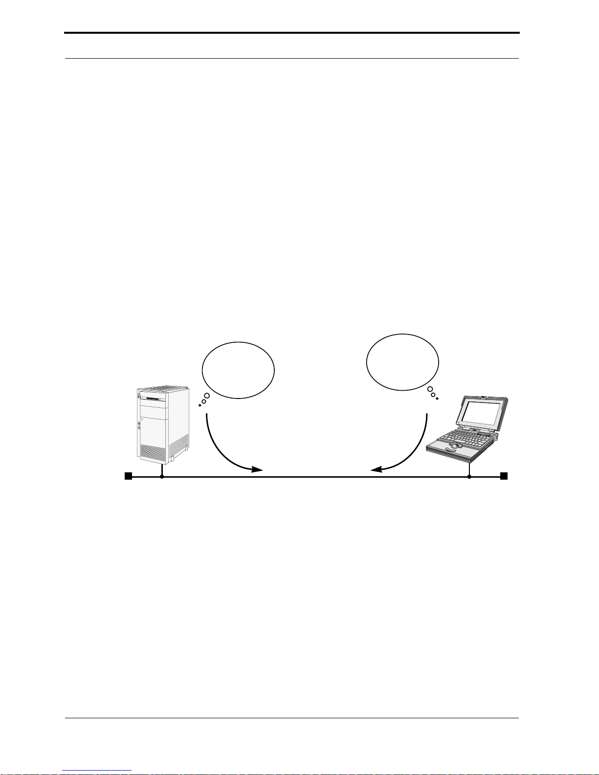
SNMP stands for the Simple Network Management Protocol and de-
fines the rules for the transfer of management information over IP networks. SNMP is implemented as a client-server system; the station “being
managed” runs the server-process, and the management station the client-process.
For example, the administrator at host “zeus” could manage the rout-
er “bingo” using an SNMP management application such as Sun’s Netmanager.
SNMP
Server
bingo
Okay,
route 1 is ...
route 2 is ...
LAN: 199.1.1.0
Show me
your route
table.
SNMP
Client
zeus
After booting, the V!CAS starts a login shell. We sometimes refer to it
as the SNMP shell because special commands can be entered from the
shell which are given directly to the V!CAS’ SNMP server-process. This
means that the V!CAS’ SNMP shell can be accessed from an SNMP client
application, as well as simple text-oriented connections such as telnet,
isdnlogin, or minipad.
But wait; before an SNMP management station can administer such
stations, it first has to know a few things about it such as what type of station it is (router, printer, bridge, …), what operating parameters can be
changed, etc. This is where the MIB or Management Information Base
comes in.
16 SNMP, MIBs, and V!CAS System Tables
Page 25

User’s Guide: Version 1.2
A MIB is a sort of database containing different variables (often referred to as objects), all of which combined, define how the V!CAS operates as a whole. The V!CAS implements differnet MIBs, including the
standard IP MIB version 2, Novell and BinTec Enterprise MIBs. Our
SNMP client-process running on zeus shown above, would need to load
MIB files locally from disk before contacting bingo.
Upon booting, the V!CAS starts an SNMP process, then reads its configuration file (covered next) and stores the information in memory. From
the SNMP shell, these variables are represented by various System Ta-
bles which are arranged into functional groups. Entering the “g” command displays a list of groups while the “l” command shows a long list
of all system tables.
Memory
Admin
IPX
Bridge
CAPI
Interface
MIB
IP
X25
ISDN
SNMP
PPP
ISDN
Ethernet
These variables can be changed by editing the system tables; the
V!CAS then updates the respective variables in memory instantly. As
mentioned earlier, the V!CAS can be managed from any of it’s ports.
Note: As soon as a variable is changed in memory, the setting
becomes effective immediately, the V!CAS does not have to
!
be rebooted nor do configuration files need be reloaded.
Any changes made to memory not saved in a configuration
file, however, are lost once the system is shut down.
SNMP, MIBs, and V!CAS System Tables 17
Page 26

V!CAS
Configuration Files, Flash, and the TFTP
As mentioned earlier, the V!CAS reads its configuration information internally from a configuration file. This file is stored in Flash EEPROM
(electronically eraseable programmable read-only memory), which we
just refer to as Flash. Actually, Flash can hold as many different files as
you need; as long as there’s enough room for them.
Think of Flash as a directory of configuration files. The files in this di-
rectory can be created, copied, moved, deleted. It’s also possible to retrieve and transmit configuration files to/from remote hosts. These actions can be performed using the Configuration Management menu in
Setup Tool or from the SNMP shell by using special commands. Refer to
the description on this menu in Chapter 4 for more information on the
various commands and parameters.
<
Flash File
<
New Flash File
Flash
REORG
>
COPY
VE
MO
DELETE
REBOO
TFTP Server
<
>
Memory
SAVE
LOAD
STA
TE
T
GET
PUT
<TFTP File>
>
The transfer of configuration files between the V!CAS and remote
hosts is made possible by the TFTP, or Trivial File Transfer Protocol. Using TFTP, it’s also possible for the V!CAS to retrieve its boot-image (or
system software) from a TFTP host. See the section on the BOOTmonitor
in Chapter 8.
18 Configuration Files, Flash, and the TFTP
Page 27

Physical and Software Interfaces
One of the central concepts used on the V!CAS is the idea of interfaces.
This section briefly explains the idea of interfaces used on the V!CAS.
As a router the V!CAS was designed to link your local and remote
networks (or hosts) using WAN links such as ISDN dialup, leased line,
and X.25 connections. To establish connections to these sites, the V!CAS
uses the Software Interfaces that you configure. By configuring a software
interface, we simply mean that you create an interface by giving it a name
and specify the characteristics of the communications link such as:
• Type of Link — what physical medium to use.
• Supported Protocols — what protocols do you want to route.
• Encapsulation — the format to use when transmitting data.
• Connection security — authentication at connect time?
User’s Guide: Version 1.2
• Network security — what types of traffic don’t you want routed.
The characteristics you configure for a software interface depend on
the capabilities of the hardware of your V!CAS. Software interfaces are
easily added or changed using the V!CAS’ Setup Tool under the WAN
Partners menu. You can create as many software interfaces as you need.
When routing, the V!CAS maps software interfaces onto physical hardware interfaces.
Let’s consider the example shown on the following page. The V!CAS
interconnects the LAN in Paris and a site in Munich with the file servers
and other hosts on the local ethernet.
Suppose host-X on the V!CAS’ LAN segment generates intermittent
bursts of traffic with a host on the Paris LAN. We might create a “parisx31” interface and configure X.31 (X.25 in the D-channel) allowing us to
take advantage of volume-based charging in X.31. All other traffic could
be routed over ISDN dialup connections.
Physical and Software Interfaces 19
Page 28

V!CAS
Munich Paris-LAN host-X
ISDN
2B + D
0
ISDN S
munich-dialup
paris-dialup
paris-x31
HW Interfaces
SW Interfaces
File Server
LAN
Ethernet
en1-snap
V!CAS
BinTec
Setup Tool vs. SNMP Shell
As mentioned earlier, administering the V!CAS’ features involves managing the various system variables (or tables of variables) defined in the
V!CAS’ MIB. Considering the close to 100 system tables and the various
interdependencies of the resulting 1000 or more variables, this can be a
daunting task when performed from the SNMP shell.
The V!CAS’ Setup Tool removes the complexity of administering the
V!CAS and allows you to configure the features you need using a simple
character based menu system.
Keeping Setup Tool character oriented means you can administer the
V!CAS and its features remotely from simple character based connections
such as telnet, terminal emulation programs, isdnlogin, and minipad.
This document describes administering the V!CAS with Setup Tool.
For info on using the SNMP shell see the Software Reference Manual.
V!CAS
20 Setup Tool vs. SNMP Shell
Page 29

Using Setup Tool
Setup Tool is an easy to use, intuitive menu-oriented program. After a
few minutes, you’ll have no problem finding your way around the various menus. In this section we’d like to point out a few things you should
be aware of when using Setup Tool.
But first, let’s look at Setup Tool’s Menu Layout and Structure.
Menu Layout
User’s Guide: Version 1.2
Navigational Aid:
Tells you where you
are in Setup Tool
menu system.
V!CAS Setup Tool BinTec Communications GmbH
[IP][
ROUTING]: IP Route Table
The flags are: U (Up), D (Dormant), B (Blocked),
Destination
199.1.2.2 199.1.1.20 255.255.255.128 US 0 en1 loc
199.1.1.0 199.1.1.2 255.255.255.128 US 0 en1 loc
ADD DELETE EXIT
Press <Ctrl-n>, <Ctrl-p> to scroll, <Space> tag/untag DELETE, <Return> to edit
Help Line:
As you move the cursor
between different fields
the help line provides
useful information.
G (Gateway Route), I (Interface Route),
S (Subnet Route), H (Host Route)
Gateway Mask Flags Me Interf/Partner Pro
V!CAS’ hostname:
Useful for sites with
several BRICKs.
vicas
Using Setup Tool 21
Page 30
V!CAS
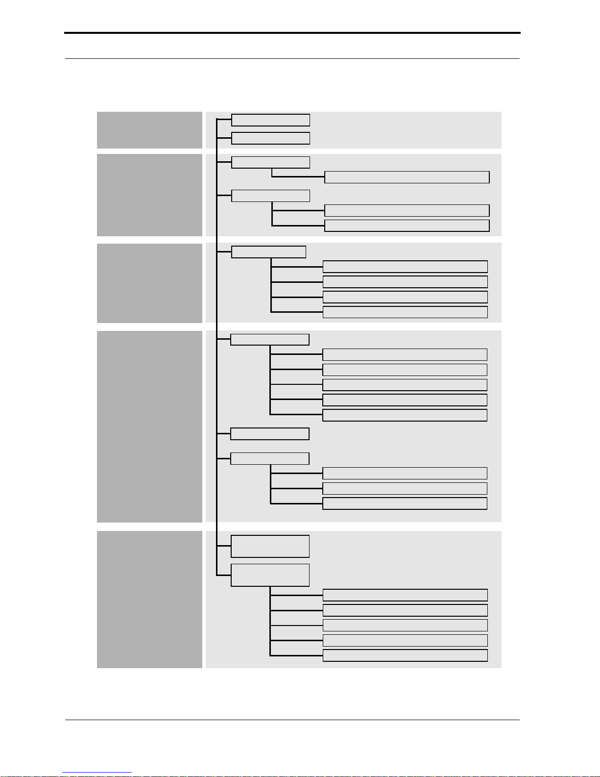
Menu Structure
Basic
System
Hardware
Interfaces
Partner
Management
Protocol
Management
Licenses
System
LAN Interface
Advanced Settings
WAN Interface
Advanced Settings
Incoming Call Answering
WAN Partner
ISDN Numbers
IP
IPX
Advanced Settings
IP
Routing
Static Settings
Network Address Translation
SNMP
Dynamic IP Address Server
IPX
System
Administration
22 Menu Structure
POTS
Static Settings
POTS A
POTS B
Configuration
Management
Monitoring &
Debugging
ISDN Monitor
X.25 Monitor
Interfaces
Messages
TCP/IP
Page 31

Special Menu Commands
While using Setup Tool you will notice that some menus have different
command options in the lower portion of the menu such as the “ADD”
“DELETE” “SAVE” and “CANCEL” commands shown below. There are
a few slight differences between these commands which you should be
aware of.
ADD DELETE SAVE CANCEL
Use <Space> to select
User’s Guide: Version 1.2
Menu Command Effect
ADD Used to create or add an item to a list.
CANCEL Discards all changes made within the cur-
rent menu. Note: ONLY the current menu.
DELETE This command deletes all entries tagged
for deletion from a list. Changes are saved
to memory and become effective immediately.
OK The changes made in the current menu are
marked, but are only saved to memory
after a SAVE is activated in the next menu.
SA VE All variables set in the current menu AND its
submenus are saved to memory . The ef fect
is that these changes become effective
immediately.
EXIT Simply return to the previous menu.
Special Menu Commands 23
Page 32

V!CAS
Menu Navigation
While using the Setup Tool the following keys can be used to navigate the
various menus.
Key Combination Meaning
Tab
or
or
Esc Esc
Ctrl
-
Return
L
Use the tab key to mov e to the next field entry.
Use the Return key to enter a submenu or to
activate a menu command
(such as SAVE, EXIT, or DELETE).
Scroll backwards or forwards among a list of
required entries.
Use the up and down cursor keys to move forwards or backwards among menu fields.
Entering the escape key two times successively
aborts changes made and returns you to the
previous menu.
Use the spacebar to toggle the delete flag for
special entries that may be deleted.
While holding down the Control-Key press L to
redraw the screen.
Ctrl
Ctrl
Ctrl
Ctrl
N
-
P
-
B
-
F
-
24 Menu Navigation
While holding down the Control-Ke y press N to
jump to the next item in a list.
While holding down the Control-Key press P to
jump to the previous item in a list.
While holding down the Control-Key press B to
scroll back a page in a long list. At the top right
edge of the list there will be either a »=« (top of
list) or a »^« (more to come).
While holding down the Control-Key press F to
scroll forward a page in a long list. At the bottom right edge of the list there will be either a
»=« (bottom of list) or a »v« (more to come).
Page 33

4
1SETUP TOOL MENUS
What’s covered
• Basic System Configuration..................................................................28
• Hardware Interfaces.............................................................................32
• Partner Management...........................................................................40
• Configuring Protocols ...........................................................................53
• System Administration...........................................................................87
In the previous chapter we gave you a brief overview of
working with the V!CAS and described how you can administer it using the SNMP shell, or Setup Tool.
In this chapter we’ll cover all of the menus and settings
you’ll see while using Setup Tool. This chapter is divided
into five sections which correspond to the Setup Tool Main
Menu.
• Basic System Configuration
• Hardware Interfaces
• Partner Management
• Configuring Protocols
• System Administration
Each menu is identified according to its location in relation
to the Main Menu such as .
WAN PARTNER
ADD
IP
V!CAS User’s Guide 25
Page 34

V!CAS
Setup Tool Main Menu
After entering setup from the shell prompt Setup Tool’s Main Menu is
displayed as below. Depending on your hardware setup and software
configuration your V!CAS’ menu may differ slightly.
LICENSES
SYSTEM
Used for entering the serial number licensing information.
Contains basic administration information such as system
name, security passwords, and system logging parameters.
LAN Interface
WAN Interface
Feature Module
Used for configuring the ethernet interface.
Used for configuring the ISDN interface.
Displays the type of the feature module installed in
your V!CAS.
V!CAS Setup Tool BinTec Communications GmbH
Licenses
LAN Interface: CM-BNC/TP, Ethernet
WAN Interface: CM-1BRI, ISDN S0
System
vicas
Feature Module: CM-POTS-MOD1-14
WAN Partner
IP IPX X.25 POTS MODEM
Configuration Management
Monitoring and Debugging
Exit
Press <Ctrl-n>, <Ctrl-p> to scroll through menu items, <Return> to enter
WAN Partner
IP
IPX
X.25
Based on the information you provided in the Licenses menu,
this section lists the protocols that can be configured on your
V!CAS. Initially, only the IP protocol is listed.
Used for adding/deleting ISDN partners.
26 Setup Tool Main Menu
Page 35

User’s Guide: Version 1.2
POTS
CONFIGURATION MANAGEMENT
Here you can edit the parameters necessary for the POTS ports.
Used for managing the V!CAS’ configuration files. For
example you can save/delete files locally on the
V!CAS or on a remote IP host using TFTP.
MONITORING AND DEBUGGING
These menus are useful in debugging problems on
your network and allow you to monitor the V!CAS’
ISDN and X.25 interfaces, TCP/IP traffic by interface
or protocol, and syslog messages.
Setup Tool Main Menu 27
Page 36

V!CAS
Basic System Configuration
LICENSES
licenses
The upper portion displays a status for each of the V!CAS’ subsystems
based on the installed licenses listed in the lower portion. V arious subsystems are required for different features to operate on the V!CAS.
Available subsystems and possible statuses include:
Subsystem BRIDGE CAPI TAPI IP IPX OSPF STAC X25
Status builtin valid not_valid
Until a license is installed the list is empty and only IP and TAPI are
available (builtin).
V!CAS Setup Tool BinTec Communications GmbH
[
LICENSE]: Licenses vicas
Available Licenses:
IP (builtin), TAPI (builtin), OSPF (valid), CAPI (valid), BRIDGE (valid),
X25 (valid), IPX (valid), STAC (valid)
Serialnumber Mask Key State
101546 311 88PNUPZ ok
ADD DELETE EXIT
Press <Ctrl-n>, <Ctrl-p> to scroll, <Space> tag/untag DELETE, <Return> to edit
Select to enter a new license.
Select to remove a license that has been marked for dele-
ADD
DELETE
tion (using the spacebar).
Select to accept the entries and return to the main menu.
EXIT
28 Basic System Configuration
Page 37

User’s Guide: Version 1.2
SYSTEM
system
The System menu contains the V!CAS’ basic system settings. Some fields
are required for the IP and PPP protocols, and others are optional variables that contain administrative information.
V!CAS Setup Tool BinTec Communications GmbH
[
SYSTEM]: Change System Parameters vicas
System Name vicas
Local PPP ID (default) vicas
Location building 14, 3rd floor, room f
Contact Joe Brick (joe@vicas.com)
admin Login Password/SNMP Community bintec
read Login Password/SNMP Community public
write Login Password/SNMP Community public
RADIUS Server Password
HTTP Server Password bintec
Syslog output on serial console no
Message level for the syslog table debug
Maximum Number of Syslog Entries 20
External System Logging >
SAVE CANCEL
Enter string, max length = 34 chars
System Name = Defines the V!CAS’ system name and is used by IP
as the hostname. If the system name is not set, the V!CAS displays a
warning message to the screen when the admin user logs in.
Local PPP ID = This field is required by the PPP to identify your
V!CAS at connection time for IP partners configured for PAP or CHAP
authentication.
Location = (optional) The physical location of your V!CAS.
Contact = (optional) Person responsible for this V!CAS. This text
string must contain a valid email address if the system adminstrator is
to be contaced from the V!CAS’ HTTP status-page.
Login Password/SNMP Community = These three fields define the
passwords requir ed for the admin, r ead, and write users. User r estric-
tions are shown in the table below.
Basic System Configuration 29
Page 38

V!CAS
User Restrictions
Execute shell commands Read
System
Vars
admin System, IP, IPX, ISDN, X.25 ✓✓ ✓
write IP, IPX, ISDN, X.25 ✓
read IP, IPX, ISDN, X.25 ✓
1. Excluding password and license variables.
2. Changes only saved to memory (lost upon reboot).
1
1
Set
RW
Vars
✓
✓
Save
Config
Files
2
2
—
—
Note: Since the admin user has complete access to the V!CAS’
configuration information, the admin password should be
!
protected.
RADIUS Password = Required for sites using RADIUS servers for user
authentication.
HTTP Server Password = Required for viewing the HTTP status pages
of your V!CAS. You should change this password from its default value bintec.
Syslog output on serial console = Specifies whether to display system messages to the console and may be useful when debugging.
Message level for the syslog table = Specifies a priority level for
messages sent to the console. Only system messages with a priority
less than or equal to this value are displayed. Possible levels include:
Highest priority debug DebugEmergency
emerg Emergency Messages
alert Alert Messages
crit Critical Messages
err Error Messages
warning Warning Messages
notice Notice Messages
lowest priority info Info Messages
30 Basic System Configuration
Page 39

User’s Guide: Version 1.2
Maximum Number of Syslog Entries = This field defines the maximum number of messages to save, older messages are discarded. The
date, text, and time messages were sent can be seen in the
MONITORING AND DEBUGGING
MESSAGES
menu.
SYSTEM
EXTERNAL SYSTEM LOGGING
extsyslog
The External System Logging menu contains a list of Log Hosts to send
system and/or accounting messages to.
Note: Generally it’s not a good idea to send messages to hosts
accessible over dialup ISDN interfaces.
Select to create a new log-Host.
Select to remove a host which has been marked for deletion.
Select to accept the list and return to the system menu.
V!CAS Setup Tool BinTec Communications GmbH
[
SYSTEM][LOGGING]: External System Logging vicas
ADD
DELETE
EXIT
Log Host Level Facility Type
ADD DELETE EXIT
For each host the following parameters must be set.
LogHost = An IP address of a host to send messages to.
Level = Defines the level of messages to send to this host. See “Mes-
sage level for the syslog table” (p. 30) for info on message levels.
Facility = The facility on the log host, messages should be sent to. For
UNIX hosts, this facility (level 0 – 7) must be configured appropriately.
For PCs, you will need a separate application such as DIME Syslog.
Type = T ype of messages to send to host (system, accounting, or both).
Basic System Configuration 31
Page 40

V!CAS
Hardware Interfaces
LAN Interface : bnctp
CM-BNCTP, ETHERNET
This menu contains settings for the ethernet interface of your V!CAS.
V!CAS Setup Tool BinTec Communications GmbH
[
LAN]: Configure Ethernet Interface vicas
IP-Configuration
local IP-Number 199.1.1.2
local Netmask 255.255.255.0
Encapsulation Ethernet II
IPX-Configuration
local IPX-NetNumber 0
Encapsulation none
Bridging enabled
Advanced Settings >
SAVE CANCEL
Enter IP address (a.b.c.d or resolvable hostname)
IP-Configuration
local IP-Number = The IP address of the LAN interface.
local Netmask = The netmask to use for this interface.
Encapsulation = Defines the type of header applied to IP packets sent
over the LAN; either “Ethernet II” and “Ethernet SNAP” may be used.
IPX-Configuration
local IPX-NetNumber = Defines the IPX network number assigned
to the LAN connected to this interface.
32 Hardware Interfaces
Page 41

User’s Guide: Version 1.2
Encapsulation = Defines the type of header applied to IPX packets
sent over this interface.
Supports
IPX Encapsulation
IP IPX X.25 Bridging
Ethernet II ●●
Ethernet SNAP ●●
Ethernet 802.2 LLC ●●●
Novell 802.3 ●
Bridging = Setting to “on” allows bridging packets to pass over this inter-
face. Set to “off” to disable.
Hardware Interfaces 33
Page 42

V!CAS
CM-BNCTP, ETHERNET
V!CAS Setup Tool BinTec Communications GmbH
[
LAN][ADVANCED]: Advanced Settings vicas
RIP Send RIP V2
RIP Receive RIP V2
IP Accounting on
Proxy Arp off
SAVE CANCEL
ADVANCED SETTINGS
bnctp.adv
Use <Space> to select
RIP Send = Specifies which types of Routing Information Protocol
(RIP) packets to send on this interface. When version 2 RIP packets are
used, the V!CAS also sends the netmask of propagated IP addresses.
This allows the V!CAS to propagate RIP packets to networks that do
not use the default netmask for their respective network class.
RIP Receive = Specifies which types of RIP packets to accept (or ignore) from this interface.
IP Accounting = Turns IP accounting on or off for this interface.
When turned on, accounting information for each TCP, UDP, or ICMP
session routed over this interface is recorded in the ipSessionTable.
Once a session is closed, an accounting record is generated and stor ed
in the syslog table. Accounting records can be seen in the Setup Tool
MONITORING AND DEBUGGING
MESSAGES
menu.
Proxy Arp = Turns proxy ARP for this interface to on or off. When
turned on, the V!CAS answers all ARP requests received on this interface, with its own hardware address.
34 Hardware Interfaces
Page 43

User’s Guide: Version 1.2
WAN Interface : 1bri
CM-1BRI, ISDN S0
This menu contains settings for the ISDN interface.
V!CAS Setup Tool BinTec Communications GmbH
[
WAN]: WAN Interface vicas
Result of autoconfiguration: Euro ISDN, point to multipoint
ISDN Switch Type autodetect on bootup
D-Channel dialup
B-Channel 1 dialup
B-Channel 2 dialup
Incoming Call Answering >
Advanced Settings>
SAVE CANCEL
Use <Space> to select
Result of autoconfiguration = The status of ISDN autoconfiguration
for this interface. The autodetection procedure runs until a successful
detection or the switch type (see below) is set manually.
ISDN Switch Type = Defines the switch type your ISDN provider
uses. In most cases “autodetect on bootup” will detect the proper
switch type. If the switch type is set manually, the autodetection feature is disabled for this interface.
The follwoing protocols are supported for dialup and leased lines.
ISDN Dialup Lines ISDN Leased Lines
• Euro ISDN
• 1TR6
• AT&T 5ESS Custom ISDN
• ISDN 1 AT&T NI1, EWSD NI1
• National ISDN 1 Northern
Telecom DMS100
• Japan NTT INS64
• leased line B1 channel (64S)
• leased line B1+B2 channel (64S2)
•leased line D+B1+B2 channel (TS02)
Hardware Interfaces 35
Page 44

V!CAS
D-channel = Most sites should leave these settings to their default
values. However, if you have arranged special ISDN services from
your provider the D-channel can (and must) be set to operate as DTE
or DCE for the local side of a leased line connection. Note that the remote side must be configured opposingly.
B-channel 1 = Most sites should leave these settings to their default
values. These settings should only be changed for sites requiring special configurations (as noted in D-channel above).
B-channel 2 = How to use the second B-channel. See above.
SPID B-Channel 1+2 = Required for the AT&T protocols and sets the
SPID (Service Profile Identifier) to use for both B-channels.
SPID B-channel 1 = Required for the National ISDN 1 Northern T ele-
com protocol and sets the SPID to use for the first B channel.
SPID B-channel 2 = Required for the National ISDN 1 Northern T ele-
com protocol and sets the SPID to use for the second B channel.
Incoming Call Answering B1 = Under the National ISDN 1 North-
ern Telecom protocol, incoming call answering procedures must be
specified for each B-channel.
See the
CM-1BRI, ISDN S0
INCOMING CALL ANSWERING
menu on page 37.
Incoming Call Answering B2 = See above.
36 Hardware Interfaces
Page 45

User’s Guide: Version 1.2
CM-1BRI, ISDN S0
INCOMING CALL ANSWERING
1bri.callans
The settings in this menu are used to distribute incoming ISDN calls received on this interface to different service items. The V!CAS distinguishes incoming calls based on the “Called Party’s Address” transmitted in
ISDN.
For example you might want an incoming call from a particular ISDN
station to automatically receive the login service. However, you’ll probably want most calls to be given to the routing service.
By default all incoming calls are dispatched to the login service.
V!CAS Setup Tool BinTec Communications GmbH
[
WAN][INCOMING]: Incoming Call Answering vicas
Item Number Mode
ADD DELETE EXIT
The incoming call answering is handled by the entries in this list. At
first the list will be empty. Choose to create a new entry or se-
ADD
lect an existing entry and press <Return> to edit it. You will then get a
new screen, where you can specify the Item, Number and Mode settings.
Hardware Interfaces 37
Page 46

V!CAS
Item = the ISDN service you want to use for this call. You can select
one of the following:
Value Meaning
Default value, good for all PPP connection
types listed below (except for the specific
PPP (routing)
ISDN Login login service
PPP 64k 64kbps PPP data connection
PPP 56k 56kbps PPP data connection
PPP Modem Profile 2 … 8 settings) if the calls
are signalled correctly (as is the case in most
of Europe).
If in doubt, try this value.
PPP Modem
PPP DOVB
PPP V.110
(1200 - 38400)
Pots put the call through to the POTS ports
PPP Modem
Profile 1 … 8
CAPI 1.1 EAZ 0 … 9
Mapping
selects Modem Profile 1 as configured in the
[
MODEM
data transmission over voice bearer; useful
e.g. in the US where voice calls sometimes
cost less than data connections
bit-rate adaption according to V.110
(1200 bps, 2400 bps, …, 38400 bps)
selects Modem Profile 1 … 8 as configured in
the
EAZ mapping for CAPI 1.1 applications
]
menu
[
MODEM
]
menu
Number = the telephone number to use for this item.
Mode = the direction for matching the incoming telephone number
(Called Party Number), either starting from the right (right to left, this
is the default), or from the left (left to right (DDI), only useful for the
Direct Dial In (DDI) feature of point-to-point ISDN accesses.
1. Called »Anlagenanschluß« in Germany
38 Hardware Interfaces
1
Page 47

User’s Guide: Version 1.2
CM-1BRI, ISDN S0
V!CAS Setup Tool BinTec Communications GmbH
[
WANI][Advanced]: Advanced Settings vicas
X.31 TEI Value specify
Specify TEI Value 0
X.31 TEI Service Packet Switch
SAVE CANCEL
ADVANCED SETTINGS
1bri.adv
Use <Space> to select
X.31 TEI Value = This is an optional field for sites that need to custom-
ize the TEI (Terminal Endpoint Identifier) used for this interface. The
TEI value can be verified by your ISDN provider. T o enable X.31 select
“specify” and then specify your TEI.
X.31 TEI Service = Most sites will leave this settings to “Packet
Switch”. May also be set to “CAPI” or “CAPI Default”.
Hardware Interfaces 39
Page 48

V!CAS
Partner Management
WAN PARTNER
wanpartners
This menu lists all ISDN partners currently configured on your system.
The list displays each parter ’s name, the protocol used, and the current
state, i.e. active (connected) or dormant (disconnected).
V!CAS Setup Tool BinTec Communications GmbH
[
WAN]: WAN Partners vicas
Current WAN Partner Configuration
Partnername Protocol State
partnerbrick ppp dormant
ADD DELETE EXIT
Press <Ctrl-n>, <Ctrl-p> to scroll, <Space> tag/untag DELETE, <Return> to edit
T o edit an existing partner fr om the list, first highlight the partner , then
enter <Return>.
Select to create a new ISDN partner.
Select to remove a partner configuration that has been
ADD
DELETE
marked for deletion (Using the spacebar.).
Select to accept the partner list and return to the main
EXIT
menu.
40 Partner Management
Page 49

User’s Guide: Version 1.2
WAN PARTNER
ADD
waddpartners.add
This menu is where you add (or change) ISDN partner configurations. If
you are editing an existing partner, the current settings are displayed. If
you’re adding a new ISDN partner , the default values for a dialup IP partner are shown.
V!CAS Setup Tool BinTec Communications GmbH
[
WAN][ADD]: Configure WAN Partner vicas
Partner Name
Enabled Protocols <X> IP < > IPX < > BRIDGE < > X.25
Encapsulation PPP
Identify by Calling Number no
PPP Authentication Protocol CHAP and PAP
Partner PPP ID
Local PPP ID
PPP Password
ISDN Numbers >
IP >
IPX >
Advanced Settings >
vicas
SAVE CANCEL
Enter string, max length = 25 chars
Partner Name = Enter a unique name to identify your partner. If the
ISDN partner is a BIANCA/BRICK, this should be set to the BRICK’s
hostname.
Enabled Protocols = Depending on the type of traffic you will be
routing with this partner, select the protocols the link to this partner
will support.
Encapsulation = Defines the type of encapsulation to use over this
link. Depending on which protocols you enabled for this partner, the
available encapsulation methods will vary.
Also note that encapsulations using ST AC compr ession are only avail-
able if STAC is licensed on your V!CAS.
See the table below for encapsulation characteristics.
Partner Management 41
Page 50

V!CAS
WAN Partner Link Encapsulation
Compression Encapsulation Protocol
— PPP
STAC PPP + Compression
— Async PPP over X.75
— Async PPP over X.75/T.70/BTX
— Multi-Protocol LAPB Framing
V.42 bis Multi-Protocol LAPB Framing + Compression
— Multi-Protocol HDLC Framing
— HDLC Framing (only IP)
— LAPB Framing (only IP)
V.42 bis LAPB Framing (only IP) + Compression
— X.25_PPP
STAC X.25:PPP + Compression
— X.25
— X31 B-Channel
— X.25 No Signalling
IPX
Bridge
IP
X.25
Identify by Calling Number =This determines whether this partner
should be identified using the Calling Party’s Number in ISDN. Note,
if turned off, the partner must be identified using either PAP or CHAP
authentication protocols.
The following three settings only apply if PPP (or X.25_PPP) encapsulation is being used.
PPP Authentication Protocol = Specifies how this partner is authenticated at connection time. If calling line identification is not used, at
least one authentication mechanism must be used.
Partner PPP ID = The PPP ID this caller must use at connection time.
42 Partner Management
Page 51

User’s Guide: Version 1.2
Local PPP ID = The PPP ID your V!CAS should use for this partner.
The Local PPP ID from the menu is displayed as a default
SYSTEM
setting.
PPP Password = The password this partner uses at connection time.
ISDN Ports to use = This field defines which ISDN interfaces can be
used to open connections with this partner. The list only displays the
ISDN D-channel stacks that are currently available.
Partner Management 43
Page 52

V!CAS
WAN PARTNER
ADD
ISDN NUMBERS
wannpartners.isdnnumbers
This menu lists the ISDN telephone numbers this ISDN partner can be
reached at. If you’re configuring a new ISDN partner the list is empty.
V!CAS Setup Tool BinTec Communications GmbH
[
WAN][ADD][ISDN NUMBERS]: ISDN Numbers () vicas
ISDN Numbers for this partner:
ISDN Number Direction
ADD DELETE EXIT
Select to add a new ISDN number. In the subsequent dia-
ADD
logue, enter an ISDN telephone number this partner can be reached at.
Instead of just entering a single telephone number in the ISDN
Number field, you can also use wildcards to make entries for groups of
numbers. The table below lists the currently supported wildcards.
ISDN Number Wildcard Matching
*
?
[ ]
{ }
Match zero or more digits. 45* matches any number
beginning with 45, i.e., 45, 4512, 4512345, 459, etc.
Match any single digit. 5? matches 50 through 59.
Brackets denote a set of possible digits to match.
A hyphen may be used for inclusive ranges.
21[45] only matches 214 or 215 (4 or 5)
21[6-8]matches 216, 217, 218 (6 through 8, inclusive)
21[^9] matches 210 through 218. (not 9)
Curly braces denote an optional string to match.
{
0911}2145 matches 09112145 and 2145 (optional)
44 Partner Management
Page 53

User’s Guide: Version 1.2
Note: If the Calling Party’s Number from the incoming call
matches an ISDN Number entry with wildcards and an
entry without wildcards, the entry without wildcards is
always used.
Select to remove an entry that has been tagged (using the
DELETE
spacebar) for deletion.
Select to accept the list of ISDN number(s) and return to
EXIT
the previous menu.
To change an existing ISDN number, highlight the entry and then enter <Return>.
Partner Management 45
Page 54

V!CAS
WAN PARTNER
ADD
IP
wanpartners.add.ip
Use this menu to set this partner’s IP address and netmask.
V!CAS Setup Tool BinTec Communications GmbH
[
WAN][ADD][IP]: IP Configuration () vicas
IP Transit Network no
Partner’s LAN IP Address
Partner’s LAN Netmask
SAVE CANCEL
Use <Space> to select
Transit Network = Specifies whether to use a transit network between
the V!CAS and this partner’s LAN. Most sites will not require a transit
network and can leave this set to “no”.
If you use a transit net (“yes”), you’ll also have to set the ISDN IP
addresses for both sides of the connection.
Assign “dynamic” if the V!CAS receives its IP address and the IP
addresses for the primary and secondary domain name server from
this partner at connection time.
local ISDN IP Address = The V!CAS’ IP address on the transit network.
Partner’s ISDN IP Address = The partner ’s IP address on the transit
network.
Partner’s LAN IP Address = The partner’s IP on the remote LAN.
Partner’s LAN Netmask = The netmask to use for the remote LAN.
Only required for LANs using non-standard netmasks. If left blank, a
standard netmask for the respective network class will be used.
46 Partner Management
Page 55

User’s Guide: Version 1.2
WAN PARTNER
ADD
IPX
wan.partners.ipx
This menu is available if the IPX protocol is enabled for this W AN partner .
V!CAS Setup Tool BinTec Communications GmbH
[
WAN][ADD][IPX]: IPX Configuration () vicas
IPX NetNumber 0
Send RIP/SAP Updates triggered + piggyback(on changes, per. if link active)
Update Time 60
Age Multiplier 4
OK CANCEL
Enter integer value
IPX NetNumber = This is the IPX network number of the WAN link
and is required by some IPX routers.
Send RIP/SAP Updates = Determines how often RIP (Routing Infor-
mation Protocol) and SAP (Service Advertising Protocol) packets are
sent to this remote partner.
In IPX networks, RIP and SAP packets are broadcast to adjacent
networks to inform them of current routes and services. The traffic
generated by RIP and SAP is okay for LANs but for adjacent networks
connected over WAN interfaces, consideration must be made.
The following table shows the types of updates that can be configured for IPX partners.
Partner Management 47
Page 56

V!CAS
Open
new
link?
timed
update
piggyback never yes yes
triggered
+ piggyback
triggered
passive
triggered
off never no no
always yes yes May lead to higher ISDN costs.
only for
changes
only for
changes
never yes no
Send
changes?
yes yes
yes no
Send
Periodic
updates? Drawback
At least 1 static route/service
must be configured for partner
default setting
(sufficient in most cases)
Less traffic but is less reliable
than triggered + piggyback.
At least 1 static route/service
must be configured for partner
All routes/services must be
configured statically.
Update Time = Determines how often periodic updates are sent.
Age Multiplier = Used only for aging of existing routes/services.
Routes and services not updated within
<update time> x <age Multiplier> seconds are removed.
48 Partner Management
Page 57

User’s Guide: Version 1.2
WAN PARTNER
ADD
ADVANCED SETTINGS
wan.advanced
This menu is used to enable special features for the respective partner.
V!CAS Setup Tool BinTec Communications GmbH
[
WAN][ADD][ADVANCED]: Advanced Partner Setttings () vicas
Callback no
Static Short Hold 20
Delay after Connection Failure 300
Channel-Bundeling dynamic
Total Number of Channels 2
RIP Send RIP V1
RIP Receive RIP V1 + V2
Van Jacobson Header Compression off
IP Accounting off
Dynamic IP-Address Server off
Layer 1 Protocol ISDN 64 kbps
Provider Configuration >
OK CANCEL
Use <Space> to select
Callback = If callback is “expected” the V!CAS calls this partner,
hangs up, and waits for the partner to call back. “yes” means: if this
partner requests a connection (by calling the V!CAS), terminate the
call and initiate a new connection to this partner.
Note: Using CLID (see Identify by Calling Number in the previ-
ous menu) avoids incurring charges for the initial call, but is
!
a less secure means of authentication when used without
PAP and or CHAP.
Static Short Hold = Defines the number of seconds to wait before
closing all data channels to this partner once the line becomes silent.
Delay after Connection Failure = The number of seconds to wait
before allowing new connections with this partner after a connection
failure. Upon failures the interface is blocked for this many seconds.
Channel-Bundeling = The type of channel-bundeling to use for this
partner. The number of channels (N in the table below) is defined by
the next field “Total Number of Channels”.
Partner Management 49
Page 58

V!CAS
Open extra
Type
static No N N
dynamic Yes 1 N
no No 1 1
channels based
on throughput
Channels to
open initially
Max # of
channels
“static” means always keep N channels open for connections to this
partner. When a connection is established with this partner, N channels are opened, and remain open until the link is closed.
“dynamic” means monitor throughput, and open additional ISDN
channels to this partner only when needed. Initially, 1 ISDN B-channel
is opened.
Total Number of Channels = Defines the max # of channels to have
open with this partner. If static channel-bundeling is being used, this
also defines the # of channels to open at connection time.
RIP Send = Which types of RIP packets to send to this partner. If
RIPv2 packets are sent, the V!CAS also sends the netmask of the propagated IP address, which allows the V!CAS to propagate RIP packets
to networks that do not use the default netmask for their respective
network class.
RIP Receive = Which types of RIP packets to accept (or ignore) from
this partner.
Van Jacobson Header Compression = If turned “on” the TCP/IP
packet headers are compressed according to RFC 1144, resulting in a
better data-to-overhead-ratio, especially when using smaller packet
sizes.
IP Accounting = If IP Accounting is turned “on” accounting messages will be stored for each TCP, UDP, or ICMP session routed between
this partner.
See the section on the
MONITORING AND DEBUGGING
MESSAGES
menu for information on the format of accounting messages.
50 Partner Management
Page 59

User’s Guide: Version 1.2
Dynamic IP-Address Server = Set to “on” if you want the V!CAS to
assign this partner a fresh IP address at connection time. The next free
IP address is taken from the pool of addresses defined under
IP
DYNAMIC IP ADDRESSES
. This partner can also—on
request—get its domain name server addresses from the V!CAS.
Layer 1 Protocol = This entry only has an effect on outgoing calls to
this partner and on incoming calls which are identified by their calling
party number. For an outgoing modem connection you should select
one of the eight modem profiles.
The Layer 1 Protocol for incoming calls not identified by their calling
party number—which will probably the case for most incoming modem connections, as they usually originate from the analogue telephone network, where no calling party numbers are supplied with the
☞
calls—is taken from the settings.
INCOMING CALL ANSWERING
The following table shows the possible values for the Layer 1 Protocol
entry.
Note that most entries correspond to similar entries in theItem field
of the menu explained on page 37.
INCOMING CALL ANSWERING
Value Meaning
ISDN 64kbps 64kbps ISDN data connection
ISDN 56kbps 56kbps ISDN data connection
Modem
DOVB
V.110 (1200 - 38400)
selects Modem Profile 1 as configured in the
[
MODEM
data transmission over voice bearer; useful
e.g. in the US where voice calls sometimes
cost less than data connections
bit-rate adaptation according to V.110
(1200 bps, 2400 bps, …, 38400 bps)
]
menu
Modem Profile 1 … 8
selects Modem Profile 1 … 8 as configured in
the
[
MODEM
]
menu
Partner Management 51
Page 60

V!CAS
WAN PARTNER
ADD
ADVANCED SETTINGS PROVIDER CONFIGURATION
You can use this menu to configure dialup IP connections to CompuServe
Online Services. The menu contains user access information (host machine, member ID, and password) which is used to generate biboPPPLog-
inString used at connection time.
V!CAS Setup Tool BinTec Communications GmbH
[
WAN][EDIT][ADVANCED][PROVIDER]: Provider Configuration(cis) vicas
Provider Compuserve Network
Host CIS
User ID 12345,6789
Password secret
OK CANCEL
prov
Use <Space> to select
Provider = Defines the type of access to CompuServe and may be one
of the following:
Online Provider Encapsulation in WAN Partner menul
not defined (default v alue, i.e. do not use this option)
Compuserve via T-Online async PPP over X.75/T.70NL/T-Online
Compuserve
Corporate
Network
Compuserve Network async PPP over X.75
1. For direct access.
2. For indirect access via the T-Online gateway.
async PPP over X.75
async PPP over X.75/T.70NL/T-Online
1
1
2
2
Host = The CompuServe hostname to dial into.
User ID = The user’s CompuServe Member ID to use for the connec-
tion.
Password = The password to use for the User ID specified above.
52 Partner Management
Page 61

Configuring Protocols
User’s Guide: Version 1.2
IP
ip
The IP menu consists of several submenus which contain global settings
for the IP and some special IP-related features. Most of the menus contain
optional settings, specific to a particular feature.
V!CAS Setup Tool BinTec Communications GmbH
[IP]
: IP Configuration vicas
Routing
Static Settings
Network Address Translation
Access Lists
Dynamic IP Addresses (Server Mode)
DHCP Server
SNMP
OSPF
EXIT
Press <Ctrl-n>, <Ctrl-p> to scroll through menu items, <Return> to enter
ROUTING
STATIC SETTINGS
contains the IP routing table of your V!CAS.
contains some required parameters such as the
V!CAS’ domain name, as well as IP addresses for optional servers.
Network Address Translation
is used to configure different inter-
faces for Network Address Translation.
ACCESS LISTS
is used to configure different access lists which can
be used to control access to/from hosts on the connected networks.
DYNAMIC IP ADDRESSES
is used to manage the pool of IP
addresses the V!CAS uses when operating as an IP address server.
DHCP SERVER
contains resources the V!CAS will use when acting
as a Dynamic Host Configuration Protocol server.
SNMP
OSPF
contains basic settings required for the SNMP.
contains settings required for the OSPF r outing protocol.
Configuring Protocols 53
Page 62

V!CAS
IP
ROUTING
ip.routing
This menu displays the current IP routing table. Fr om this menu you can
edit exisiting IP routes or add new ones. Note that IP routes learned
through the RIP can’t be changed, only deleted.
For the most part, the columns are self explanatory:
V!CAS Setup Tool BinTec Communications GmbH
[IP][
ROUTING]: IP Routing vicas
The flags are: U (Up), D (Dormant), B (Blocked),
G (Gateway Route), I (Interface Route),
S (Subnet Route), H (Host Route)
Destination Gateway Mask Flags Me Interf./Partner Pro
199.1.1.0 199.1.1.2 255.255.255.0 US 0 en1 loc
ADD DELETE EXIT
Press <Ctrl-n>, <Ctrl-p> to scroll, <Space> tag/untag DELETE, <Return> to edit
To add a new IP route select .
ADD
To edit an existing route, highlight the entry and enter <Return>.
To remove one or more IP routes, mark the entries for deletion using
the spacebar, then select .
Select to accept the entries and return to the menu.
EXIT
DELETE
IP
Note that the changed routing table becomes effective immediately.
54 Configuring Protocols
Page 63

User’s Guide: Version 1.2
IP
ROUTING ADD
ip.routing.add
Use this menu to add (or make changes) to the IP routing table.
V!CAS Setup Tool BinTec Communications GmbH
[IP][
ROUTING][ADD]: Add or Change IP Route vicas
Route Type Host route
Network WAN without transit network
Destination IP-Address 200.1.1.2
Partner / Interface partnerbrick
Metric 1
SAVE CANCEL
Use <Space> to select
Route Type = The type of IP route you’re adding, i.e. a route to a single host or network. If a default route is specified it will only be used
when no other matching routes are found.
Network = Use LAN for hosts (or nets) directly attached to the V!CAS.
For routes that use WAN interfaces, specify whether the route includes transfer network. If “discard” is used the V!CAS disregards all
packets matching this route.
Transit Networks: Some sites may require an intermediate transit
network (mainly sites using routing equipment from different
manufacturers). As shown below, each host on the transit network
is accessible via two different addresses.
201.1.1.1 201.1.1.2
Transit
Network
ISDN
199.1.1.1 199.1.1.2
200.1.1.1 200.1.1.2
Configuring Protocols 55
Page 64

V!CAS
Destination IP-Address = IP address of the remote host or network.
If this route uses a WAN link with a transfer network, enter the IP address of the ISDN side of the partner’s router. See diagram above.
Netmask = Only for network-routes. If left blank, a standard netmask
for the appropriate network class will be used.
Partner / Interface = For routes using a WAN link without a transfer
network, scroll through the list of WAN partners using the spacebar.
Gateway IP-Address = The host the V!CAS should forward packets
to for this route, often called the “Next-Hop”.
Metric = The metric value for this route. Metric values with a lower
priority have precedence.
56 Configuring Protocols
Page 65

User’s Guide: Version 1.2
IP
STATIC SETTINGS
ip.advan
Thie Static Settings menu contains some of the basic settings for your
V!CAS.
V!CAS Setup Tool BinTec Communications GmbH
[IP][
STATIC]: IP Static Settings vicas
Domain Name bricks.com
Primary Domain Name Server 199.1.1.99
Secondary Domain Name Server
Time Protocol TIME/UDP
Time Offset (seconds) 0
Time Update Interval (seconds) 86400
Time Server 199.1.1.99
Remote CAPI Server TCP port 6000
Remote TRACE Server TCP port 7000
RIP UDP port 520
BOOTP Relay Server
Unique Source IP Address
RADIUS Server
HTTP TCP port 80
SAVE CANCEL
Enter string, max length = 35 chars
Domain Name = Sets the V!CAS’ IP domain name.
Primary Domain Name Server = The IP address of the V!CAS’ do-
main name server.
Secondary Domain Name Server = An alternate name server.
Time Protocol = The protocol to use to retrieve current time. The fol-
lowing protocols are possible.
Protocol Explanation
time_udp Time Service (RFC 868) via UDP
time_tcp Time Service (RFC 868) via TCP
time_sntp
isdn ISDN D-Channel
SNTP (Simple Network Time Protocol, RFC 1769) via UDP
none Disable time retrieval altogether
Configuring Protocols 57
Page 66

V!CAS
Time Offset (seconds) = The time in seconds to add/subtract to the
retrieved time. Values between -24 and +24 are assumed to be hours
and are appropriately converted to seconds. Note that when time is r etrieved from ISDN the offset must be set to zero.
Time Update Interval (seconds) = The interval in seconds at which
current time should be updated/retrieved. Similar to Time Offset values between 1 and 24 are assumed to be hours and converted to seconds. For Protocol=time_udp, time_tcp, or time_sntp new requests
are sent every Time Update Interval seconds. When isdn is used the current time will be retrieved fr om the next ISDN connection established
after Time Update Interval seconds.
Time Server = The IP address of the V!CAS’ timeserver.
Remote CAPI Server TCP port = The port number to use for CAPI
connections. Default value: 6000
Remote TRACE Server TCP port = The port number the V!CAS uses
for TRACE requests. Default value: 7000
RIP UDP port = The port number used on the V!CAS for RIP. Default
setting is 520. RIP can be disabled by assigning port 0.
BOOTP Relay Server = The BOOTP server’s IP address. If configured
the V!CAS will relay all BOOTP requests received over its LAN interface to the server. BOOTP responses received from the server are returned to the requesting client.
Unique Source IP Address = This is not the V!CAS’ IP address.
When routing to partners over a transit network, the V!CAS normally
uses the IP address of its LAN interface as the source address in IP
frames. If this is not desired, this field defines the IP address to use instead.
RADIUS Server = The RADIUS server’s IP address.
HTTP port = The port number used on the V!CAS for HTTP requests.
By default TCP port number 80 is used. Access to the V!CAS’ statuspage can be disabled by assigning port number 0 here.
58 Configuring Protocols
Page 67

User’s Guide: Version 1.2
IP
Network Address Translation
ip.nat
This menu lists all IP interfaces that may be configured for NAT. The
V!CAS supports both Forward and Reverse NAT.
V!CAS Setup Tool BinTec Communications GmbH
[IP][
NAT]: NAT Configuration vicas
Select IP Interface to be configured for NAT
en1
en1-snap
partnerbrick
EXIT
Press <Ctrl-n>, <Ctrl-p> to scroll, <Return> to edit/select
To configure an interface highlight it and enter <Return>.
Forward NAT means, allow all traffic destined (moving-forward) for
this interface. Arriving traffic is only accepted if explicitly allowed1.
Private
LAN
199.1.1.0
NAT
ISDN
Internet
Service
Provider
Internet
Reverse NAT means, allow all traffic arriving on this interface. Traffic
destined for this interface is only accepted if explicitly allowed1.
NAT
Dialup
Client
ISDN
Internet
Service
Provider
Internet
1. Or the traffic is return data from a session initiated internally.
Configuring Protocols 59
Page 68

V!CAS
IP
Network Address Translation
EDIT
ip.nat.edit
The NAT Configuration menu lists session profiles that define which session are allowed over this NAT interface. From this menu you can add,
change, or delete session profiles.
V!CAS Setup Tool BinTec Communications GmbH
[IP][
NAT][CONFIG]: NAT Configuration (en1) vicas
Network Address Translation off
Configuration for sessions requested from outside
Service Destination Source Dep. Dest. Dep. Port Remap
ADD DELETE SAVE CANCEL
Use <Space> to select
Network Address Translation = The type of NAT to perform for this
interface: “on” for forward NAT , “r everse” for r everse NAT, and “off”
to disable NAT completely.
To edit an existing session, highlight the entry and enter <Return>.
To configure a new session profile for this interface select .
ADD
To delete a session, mark the entry for deletion using the spacebar,
then select .
Select to accept the session list and return to the previous
DELETE
SAVE
menu.
Select to discard all changes made since the last SA VE and
CANCEL
return to the previous menu.
Note: Once saved, any changes made here become effective
immediately. Be aware of this when configuring NAT from
!
a remote site.
60 Configuring Protocols
Page 69

User’s Guide: Version 1.2
IP
Network Address Translation
ADD
ip.nat.add
This menu is used to add or change session profiles for a NAT interface.
Sessions configured here define the types of IP session(s), that are explicitly allowed over this NAT interface. The session profile configured here
applies to a specific host.
V!CAS Setup Tool BinTec Communications GmbH
[IP][
NAT][CONFIG][ADD]: Edit NAT Configuration (en1) vicas
Service user defined
Protocol icmp
Port (-1 for any) -1
Destination
SAVE CANCEL
Use <Space> to select
Service = The service to allow on the internal host. Several services
are already defined. To define other services, set to “user-defined” and
set the Protocol and Port fields appropriately.
Protocol = The protocol to allow for user-defined services.
Port = The port number to allow. Use “-1” to allow all ports for the
specified protocol. If a specific port is set, it must match the port
number used by the internal host.
Destination = IP address of the internal host to allow connections to.
Leaving this field empty identifies the V!CAS as the destination host.
Select to accept the session profile and r eturn to the previ-
SAVE
ous menu.
Select to abort the entries made so far and return to the
CANCEL
previous menu.
Configuring Protocols 61
Page 70

V!CAS
IP
ACCESS LISTS
ip.accesslists
This menu displays the IP Access Lists. The V!CAS has an Allow list and
a Deny list based on the mode of the entries configured here. Each entry
specifies an interface to monitor incoming traffic on and defines a set of
IP packets.
V!CAS Setup Tool BinTec Communications GmbH
[IP][
ACCESS]: IP Access Lists vicas
M (Mode) values are: a (Allow), d (Deny)
Access Lists configured:
M Prt Int./Partner Src Address Src Port Dst Address Dst Port
a tcp dialup1 any any any any
d tcp dialup1 any any any 21
d tcp dialup1 210.1.2.3/24 any any 23
d tcp dialup1 any 25-103 any clients
ADD DELETE EXIT
IP packets are tested to see if they match deny/allow entries. The de-
cision whether to route the packet is based on the following algorithm
Incoming
packet
Allow List
empty?
no
Match an
Allow entry?
no
Discard packet!
yes
yes
Deny List
empty?
no
Match a
Deny entry?
no
yes
yes
Route packet!
Using Source and Destination Port Numbers
Along with the source and destination addresses, the Internet Protocol
uses source and destination ports numbers, to identify data connections
uniquely. The client side generates a number (xyz) which is used as the
62 Configuring Protocols
Page 71

User’s Guide: Version 1.2
source port, for the destination port it uses the number the server offers
the service on. The server sends IP packets with the port numbers reversed in respect to the client. A simplified ftp connection might look like
this.
200.1.1.2
ftp
server
<xyz>199.1.1.121200.1.1.1
199.1.1.1
ftp
client
IP
➊
Src Addr Src Port Dest Addr Dest Port
ACCESS LISTS ADD
ISDN
➋
Src Addr Src Port Dest Addr Dest Port
21200.1.1.2<xyz>199.1.1.1
ip.accesslist.ad
Use this menu to create an Allow or Deny access entry. Depending on the
Mode set for the entry, the packet will be routed or dropped.
V!CAS Setup Tool BinTec Communications GmbH
[IP][
ACCESS][ADD]: Add or Change Access List Entry vicas
Mode deny
Protocol any
Source Interface/Partner dialup1
Source Address
Source Mask
Source Port specify range
Specify Port 5 to Port 100
Destination Address
Destination Mask
Destination Port specify
Specify Port 23
SAVE CANCEL
Use <Space> to select
Mode = Allow or deny the following packets to be routed.
Protocol = Set the protocol to match, or “any” to match all protocols.
Source Interface/Partner = Select the interface (or partner) to moni-
tor incoming IP frames on. Set to “any” to monitor all interfaces.
Configuring Protocols 63
Page 72

V!CAS
Source Address = (optional) Set the IP address to match frames from.
Source Mask = (optional) Apply an optional mask.
Source Port = The range of port numbers to apply. Use “specify” to
select a specific port number, “specify range” to select a range of port
numbers by entering the first and the last port to be included in the
range, “any” to match all ports numbers, or one of the predefined
ranges, as explained in the table below.
Source Port Ranges
0 ... 1023 1024 ... 4999 5000 ... 32767 32768 ... 65535
privileged unprivileged
server clients server clients
specify / specify range
Destination Address = (optional) The IP address of the destination
host to match.
Destination Mask = (optional) Apply an optional mask.
Destination Port = A range of ports to apply (see Source Port, above).
Select to accept the these settings and return to the previ-
SAVE
ous menu.
Select to abort the entries made so far and return to the
CANCEL
previous menu.
64 Configuring Protocols
Page 73

User’s Guide: Version 1.2
IP
Dynamic IP Addresses
ip.dynamicip
This menu should be used to create a pool of IP addresses theV!CAS may
use when operating as a Dynamic IP address server.
V!CAS Setup Tool BinTec Communications GmbH
[IP][
DYNAMIC]:
IP Address Number of consecutive addresses
ADD DELETE EXIT
Dynamic IP Addresses (Server) vicas
Select to add a block of addresses to the pool. You may
ADD
add single IP addresses, or a complete block of addresses. In the following
menu there are two required fields.
IP Address = Enter the first number of the address block.
Number of consecutive addresses = Enter the number of address-
es in the block including the first number.
Select to remove a block of addresses marked for deletion.
Select to return to the menu.
DELETE
EXIT
IP
Configuring Protocols 65
Page 74

V!CAS
IP
DHCP SERVER
ip.dhcpserver
The V!CAS supports the Dynamic Host Configuration Protocol which can
be used to assign local (or remote) hosts IP addresses. This menu is used
to control which IP addresses can be assigned and how long the address
is valid.
V!CAS Setup Tool BinTec Communications GmbH
[IP][
DHCP]:
Interface IPAddress Number Lease Time (Minutes)
en1 199.1.1.70 15 30
en1 199.1.1.85 5 120
tr6-snap 200.1.2.50 4 120
ADD DELETE EXIT
DHCP Server vicas
Press <Ctrl-n>, <Ctrl-p> to scroll, <Return> to edit/select
The V!CAS acts as a DHCP Server. Client machines (PCs running W indows 95/NT) that support DHCP are generally configured to retrieve
their IP address from the server and adjust their configurations appr opriately. With DHCP the retrieved IP address is only valid for a specified
time period, known as the “Lease T ime”. Once the lease time has run out,
the server is free to reassign the IP addr ess when needed. The DHCP server also informs clients of the appropriate nameserver (biboAdmNameServ-
er is used) and default gateway.
Select to add a new range of addresses; or highlight an en-
ADD
try and enter <Return> to change an existing entry. In the subsequent
menu you’ll need to enter information for the following fields.
Interface = Associates a V!CAS interface with a set of IP addresses.
The V!CAS will assign an available IP address from the appropriate
66 Configuring Protocols
Page 75

User’s Guide: Version 1.2
set of addresses depending on which interface it received the addr essrequest on.
IP Address = Defines the first IP address in the set.
Number = Defines the number of addresses in the set (including the
first address).
Lease Time = Defines the time in minutes addresses from this set are
valid. Addresses become available for reassignment once the lease
time runs out.
Internet Access for the LAN using DHCP and NAT
DHCP can be used in combination with NAT (Network Address Transla-
tion) to provide easy Internet access for a complete LAN. The main ad-
vantage is that PCs on the LAN don’t need to be configured individually.
DHCP Server
➥IP Address
➥Nameserver
➥Default Router
Windows 95
NAT
Windows 95 Windows NT
ISDN
DHCP Clients
A simplified configuration using this setup would involve:
1. Configuring Network Address Translation on the V!CAS
(only one official IP Address is required).
2. Configure V!CAS as DHCP Server.
Internet
Service
Provider
Configuring Protocols 67
Page 76

V!CAS
IP
SNMP
ip.snmp
Use this menu to change the basic settings for the SNMP, or Simple Network Management Protocol.
V!CAS Setup Tool BinTec Communications GmbH
[IP][
SNMP]:
SNMP Configuration vicas
SNMP listen UDP port 161
SNMP trap UDP port 162
SNMP trap broadcasting off
SNMP trap community snmp-Trap
SAVE CANCEL
Enter integer range 0..65535
SNMP listen UDP port = Defines the UDP port the V!CAS uses for receiving SNMP requests.
SNMP trap UDP port = Defines the UDP port the V!CAS sends SNMP
traps to when SNMP trap broadcasting is turned on.
SNMP trap broadcasting = When turned on the V!CAS broadcasts
SNMP traps over its LAN interface.
SNMP trap community = By default, the snmp-trap community is
used.
Select to accept the these settings and return to the previ-
SAVE
ous menu.
Select to abort the entries made so far and return to the
CANCEL
previous menu.
68 Configuring Protocols
Page 77

User’s Guide: Version 1.2
IPX
ipx
The IPX Configuration menu is used to set global parameters for the IPX
protocol. These settings apply to all IPX interfaces.
V!CAS Setup Tool BinTec Communications GmbH
[
IPX]:
IPX Configuration vicas
Local System Name BRICK
Internal Network Number f9000e91
enable IPX spoofing yes
enable SPX spoofing yes
NetBIOS Broadcast replication yes
SAVE CANCEL
Enter string, max length = 35 chars
Local System Name = Defines the IPX system name used by the
V!CAS. The name may not contain underscores, exclamation marks,
or dots, and must be in uppercase.
Internal Network Number = The V!CAS’ internal network number.
This value must be unique among all network numbers and defaults
to the last 4 bytes of the MAC address of your V!CAS. Change only if
this value conflicts with a remote IPX router’s net number.
enable IPX spoofing = Set to “yes” or “no” to enable/disable NCP
session watchdog spoofing and handling of ‘broadcast message waiting’ packets.
enable SPX spoofing = Set to “yes” or “no” to allow/disallow spoofing of SPX session watchdog packets. Enable this if you are using SPX
sessions over WAN links.
NetBIOS Broadcast replication = Defines how NetBIOS packets are
used.
Configuring Protocols 69
Page 78

V!CAS
“yes” all NetBIOS hosts in your network can be accessed, however
WAN links may be opened frequently.
“on LAN only”only NetBIOS hosts attached to the V!CAS via LAN
interfaces can access each other. WAN links won’t be opened for NetBIOS packets.
“no” NetBIOS hosts in different LANs can not access each other.
Selecting accepts the entries and returns to the main menu.
Selecting discards all changes made in this menu and r eturns
SAVE
CANCEL
to the main menu.
70 Configuring Protocols
Page 79

User’s Guide: Version 1.2
X.25
x25
The X.25 menu contains several submenus used to configure the X.25 protocol on the V!CAS.
V!CAS Setup Tool BinTec Communications GmbH
[
X.25]:
X.25 Configuration vicas
Static Settings
Link Configuration
Routing
Multiprotocol over X.25
EXIT
Press <Ctrl-n>, <Ctrl-p> to scroll through menu items, <Return> to enter
STATIC SETTINGS
LINK CONFIGURATION
contains the V!CAS’ X.25 address.
lists all X.25-compatible interfaces on the
V!CAS, and is used to configure them respectively.
ROUTING
MULTIPROTOCOL OVER X.25
contains the V!CAS’ X.25 routing table.
is used to configure the Multiprotocol
Routing over X.25 (MPX25) feature.
Select to return to the main menu.
EXIT
Configuring Protocols 71
Page 80

V!CAS
X.25
STATIC SETTINGS
x25.static
The X.25 Static Settings menu contains the local X.25 address.
V!CAS Setup Tool BinTec Communications GmbH
[
X.25][STATIC]:
Press <Ctrl-n>, <Ctrl-p> to scroll through menu items, <Return> to enter
X.25 Static Settings vicas
Local X.25 Address
SAVE CANCEL
Local X.25 Address = The official X.25 address of your V!CAS. Setting this variable is only required if the V!CAS is not directly connected to an official X.25 data network. When connected directly, the
V!CAS ascertains its X.25 address automatically.
The X.25 address must be set here for sites implementing private X.25
networks, or when X.25 in the B-channel is used.
72 Configuring Protocols
Page 81

User’s Guide: Version 1.2
X.25
LINK CONFIGURATION
x25.linkconfig
This menu displays a list of all interfaces that support the X.25 protocol.
The number of available interfaces listed here is a combination of hardware (which modules are installed) and software interfaces (configured
WAN partners).
• Dialup interfaces Entries for each X.25-compatible W AN part-
ner configured on the system.
• X.31 interfaces If you’re receiving X.31 services from your
ISDN provider an X.31 link is also present.
X.31 links have the format:
x31d-<slot number>-<unit number>-<TEI>
V!CAS Setup Tool BinTec Communications GmbH
[
X.25][LINK]:
X.25 Link Configuration vicas
Select link to configure
xi3
en1-llc (create new configuration)
DELETE CONFIGURATION EXIT
Press <Ctrl-n>, <Ctrl-p> to scroll, <Space> tag/untag DELETE, <Return> to edit
Before an X.25-compatible interface can be used, its link characteristics
must first be set.
To edit an X.25 link highlight the entry and then enter <Return>.
To remove an X.25 link, tag the entry for deletion (spacebar) and select
DELETE CONFIGURATION
.
Configuring Protocols 73
Page 82

V!CAS
X.25
LINK CONFIGURATION
EDIT
x25.linkconfig.edit
This menu is used to configure the basic characteristics of the X.25 link.
V!CAS Setup Tool BinTec Communications GmbH
[
X.25][LINK][EDIT]:
Link en1-llc
L3 Mode dte
L3 Window Size 128 bytes
L3 Packet Size 2
Lowest Two-Way-Channel (LTC) 1
Highest Two-Way-Channel (HTC) 2
Partner MAC Address (LLC)
Layer 2 Behaviour disconnect after timeout
Disconnect Timeout 1000
Use <Space> to select
Change X.25 Link Configuration vicas
SAVE CANCEL
Link = This is the name of the link your are editing and cannot be
changed here.
L3Mode = This defines the mode the V!CAS operates in at Layer 3 of
the X.25 protocol stack. Set to DCE if theV!CAS must provide clocking
information or DTE if provided by the remote side of link.
Lowest Two-Way-Channel (LTC) = LTC and HTC must be set to reflect the number of Virtual Channel(s) you have arranged for from
your X.25 network provider.
Highest Two-Way-Channel (HTC) = Defines the highest number that
can be assigned to a Virtual Channel.
Partner MAC Address (LLC) = Used when configuring a link for a
partner on the LAN and specifies the host’s MAC or hardware address.
Layer 2 Behaviour = Defines whether (and if so, when) the link
should be disconnected when no virtual channels are active.
Disconnect Timeout = Time in seconds to wait before closing the link
once the line becomes inactive.
74 Configuring Protocols
Page 83

User’s Guide: Version 1.2
X.25
ROUTING
x25.routing
This menu displays the X.25 routing table. X.25 routes are used for routing traffic over X.25 interfaces. Routes can be added, removed, or
changed here.
V!CAS Setup Tool BinTec Communications GmbH
[
X.25][ROUTING]: X.25 Route Table vicas
Source Link Dest. Link Dest. Link Addr. Dest. X.25 Addr.
ADD DELETE EXIT
Note that the order of routes listed here have precedence. When the
V!CAS routes X.25 packets, the first matching route is always used.
To edit an X.25 route, highlight the entry and then enter <Return>.
Select to create a new X.25 route.
Select to remove an X.25 route entry that has been tagged
ADD
DELETE
(using the spacebar) for deletion.
Select to accept the list of X.25 routes and return to the pre-
EXIT
vious menu.
Configuring Protocols 75
Page 84

V!CAS
X.25
ROUTING ADD
x25.routing.add
X.25 routes configured with Setup Tool are based on two factors.
• Source link Link X.25 call_packet first arrived on.
• Dest. X.25 Address The address the packet is addressed to.
You must define the destination link where the X.25 packets will be
routed by specifying these two parameters. Standard wildcard characters
can also be used in the Destination Address parameter.
{
123}45 Either 12345 or 45
[^5]
* Any # not starting with 5 624* All #s starting with 624
[68]
* Any # starting with 6 or 8
The order of routes is also important. An incoming call may match
more than one route. The first matching route is always used.
Also note that there are different X.25 addressing standards, and
depending on where the X.25 partner is calling from, the actual X.25 address received by the V!CAS may differ.
V!CAS Setup Tool BinTec Communications GmbH
[
X.25][ROUTING][EDIT]: Add or Change X.25 Routes vicas
Source Link any
Destination Link local
Destination X.25 Address 45*
SAVE CANCEL
Use <Space> to select
SAVE
immediately saves route to memory and returns to the
previous menu.
CANCEL
76 Configuring Protocols
discards entries made here and r eturns to previous menu.
Page 85

User’s Guide: Version 1.2
X.25
MULTIPROTOCOL OVER X.25
x25.mpr
This menu lists the Multiprotocol Routing over X.25, or MPX25, interfaces
configured on the system. MPX25 allows the V!CAS to route IP, IPX, and
Bridge, traffic over X.25 links. Each MPX25 interface defines an X.25 link
to route one or more protocols over.
Note: The underlying X.25 subsystem must first be configured
before any MPX25 interface can be configured here. See the
!
V!CAS Setup Tool BinTec Communications GmbH
[
X.25][MPR]: Multiprotocol over X.25 vicas
menus:
X.25
X.25
X.25
STATIC SETTINGS
LINK CONFIGURATION
ROUTING
Interface Name Destination X.25 Address Encapsulation
ADD DELETE EXIT
Select to create a new MPX25 link.
Select to remove an MPX25 link tagged for deletion.
Select to accept the list of MPX25 links and return to the
ADD
DELETE
EXIT
previous menu.
Configuring Protocols 77
Page 86

V!CAS
X.25
MULTIPROTOCOL OVER X.25
ADD
x25.mpr.add
Use this menu to add or change MPX25 interfaces.
V!CAS Setup Tool BinTec Communications GmbH
[
X.25][MPR][ADD]: Add or change X.25 MPR vicas
Partner Name mpxpartner1
Enabled Protocols <X> IP < > IPX < > BRIDGE
Encapsulation ip_rfc877
X.25 Destination Address 49911555
IP >
IPX >
Advanced Settings >
SAVE CANCEL
Enter string, max length = 25 chars
Partner Name = Enter a unique name to identify this MPX25 partner.
Enabled Protocols = “X” selects the protocols that can be routed (re-
ceived/transmitted) with this partner.
Encapsulation = Depending on which protocol(s) are enabled for this
partner, select the type of encapsulation to use. Note that the remote
MPX25 partner must be configured to use the same encapsulation.
Encapsulation Protocol
ip_rfc877
ip
IP
mpr
Bridge
IPX
ipx
X.25 Destination Address =The X.25 address for this partner. There
must be an appropriate X.25 route for this address in the X.25 routing
78 Configuring Protocols
Page 87

User’s Guide: Version 1.2
table. The special “{“ and “}“ characters can be used to define an optional string of digits to use when matching incoming X.25 calls. For
outgoing calls to this partner, the digits between these characters are
used. {00}4991155 matches both 004991155 and 4991155 for incoming
calls, outgoing calls are placed using 004991155.
X.25
MULTIPROTOCOL OVER X.25
ADD
IP
x25.mpr.ip
This is where you configure the IP settings for this r emote MPX25 partner
and is only available if the IP protocol has been enabled.
Note: The settings used in this menu are the same as those used in the
WAN PARTNER
ADD
46 but only apply to this MPX25 partner.
X.25
MULTIPROTOCOL OVER X.25
This is where you configure the IPX settings for the remote MPX25 partner. This menu is only available if IPX has been enabled.
IP
ADD
menu described on page
IPX
x25.mpr.ipx
Note: The settings used in this menu are the same as those used in the
IPX
ADD
menu described on page
ADVANCED SETTINGS
x25.mpr.advanced
X.25
WAN PARTNER
ADD
47 but only apply to this MPX25 partner.
MULTIPROTOCOL OVER X.25
This menu can be used to configure several advanced features, such as
RIP support, IP Accounting, and the Short Hold mechanism.
Note: The settings used in this menu are a subset of those used in the
WAN PARTNER
described on page 49 but only apply to this MPX25 partner.
ADD
ADVANCED SETTINGS
Configuring Protocols 79
menu
Page 88

V!CAS
POTS
POTS
This menu contains three submenus. Use these submenus to configure
phone numbers etc. for the two POTS ports of your V!CAS.
V!CAS Setup Tool BinTec Communications GmbH
[
POTS]: POTS Configuration vicas
Static Settings
POTS A
POTS B
EXIT
Press <Ctrl-n>, <Ctrl-p> to scroll through menu items, <Return> to enter
STATIC SETTINGS
POTS A POTS B
and are used to configure the type of device
contains the TAPI server port.
connected to the POTS ports as well as the ports’ internal and external
numbers.
Select to return to the main menu.
EXIT
80 Configuring Protocols
Page 89

User’s Guide: Version 1.2
POTS STATIC SETTINGS
POTS Static Settings
The POTS Static Settings menu contains the TAPI server port.
V!CAS Setup Tool BinTec Communications GmbH
[
POTS][STATIC]: POTS Static Settings vicas
Remote TAPI Server Port 6001
SAVE CANCEL
Enter integer range 0..65535
Remote TAPI Server Port = The TCP port number to use for TAPI
connections. Default value: 6001.
Configuring Protocols 81
Page 90

V!CAS
POTS POTS A
POTS POTS A
In the POTS A and POTS B menus you can specify the internal and external phone numbers and type or device to use for POTS port A or B respectively.
V!CAS Setup Tool BinTec Communications GmbH
[
POTS][POTS A]: POTS A Configuration vicas
Type any
Internal Number *1
External Numbers >
SAVE CANCEL
Use <Space> to select
Type = Specifies the type of device connected to this POTS port.
Type Accept calls for…
any all voice services
fax fax machines
telephony telephones
modem modems
disable no calls possible at all
Internal Number = The POTS port can be reached under this number
from the other POTS port for internal (i.e. toll-free) calls.
Note: The internal numbers should always start with either an
asterisk »∗« or a hash mark »#«. If internal numbers start
!
with a digit (0-9) you will not be able to make external
calls starting with that same digit any more.
82 Configuring Protocols
Page 91

User’s Guide: Version 1.2
POTS POTS A EXTERNAL NUMBERS
POTS POTS A EXTERNAL NUMBERS
This menu displays a list of all external numbers (MSNs) configured for
the POTS port. You can add new numbers, or change or delete existing
ones.
V!CAS Setup Tool BinTec Communications GmbH
[
POTS][POTS A][EXTERNAL NUMBERS
External Numbers Direction
1 both
ADD DELETE EXIT
Press <Ctrl-n>, <Ctrl-p> to scroll, <Space> tag/untag DELETE, <Return> to edit
]
vicas
Note that there are two fields, External Numbers and Dir ection. In the
External Numbers field you can enter an MSN, in the Direction field you
can specify whether this External Number should be used for incoming
calls only, for outgoing calls, or for both incoming and outgoing calls.
Note: You can have an arbitrary number of incoming entries, but
you should configure only one outgoing or both entry for
!
each POTS port.
This is to ensure you have a specific number for outgoing
calls.
To edit an existing number, highlight the entry and press <Return>.
To add a new number select .
ADD
To remove one or more numbers, mark the entries for deletion using
the spacebar, then select .
T o accept the entries and r eturn to the menu
select . Note that the changed numbers become effective im-
EXIT
DELETE
POTS POTS A
mediately.
Configuring Protocols 83
Page 92

V!CAS
MODEM
At the moment this menu only contains the sub-
MODEM
PROFILE CONFIGURATION
menu, where you can configure up to eight different modem profiles.
The modem profiles can be associated with the Called Party’s Number
of incoming calls in the [CM-1BRI] [Incoming Call Answering] menu. Thus,
using your available MSNs, you can create separate profiles to support
the analog equipment your remote access users (dial-up clients) will be
calling from.
In theory you could use only one profile, where all values are set to
maximum—or auto, where applicable—and let the calling modem negotiate the values it needs.
This will work in most cases—only older modems will be unable to
negotiate the necessary values—but will require more time to negotiate
the connection parameters at connect time. After starting the Setup Tool,
go to the [MODEM] [Profile Configuration] menu, and select Profile 1.
You must ensure that the modem settings correspond to the type of
fax/modem provided by your V!CAS. The settings are shown below
should be fine for 14400 modems.
V!CAS Setup Tool BinTec Communications GmbH
[
MODEM][PROFILE][EDIT]: Configure Profile vicas
Name Profile 1
Description
Modulation V.32bis
Error Correction LAPM
Automode on
Min Bps 300
Max Receive Bps 14400
Max Transmit Bps 14400
V.42bis Compression auto
MNP5 Compression auto
SAVE CANCEL
Enter string, max length = 48 chars
84 Configuring Protocols
Page 93

User’s Guide: Version 1.2
The fields in this menu have the following meanings:
Name = Profile 1…8. Cannot be changed.
Note that Profile 1 is used as the default profile for modem connections,
!
if no other profile is explicitly specified.
Description = descriptive string for this profile.
Modulation = modem standard to use, select with the space bar. Val-
ues range from K56flex down to Bell 103. Make sure you select a mod-
ulation that your feature board’s modem supports; V.34 or below for
33600 modems/V32bis or below for 14400 modems.
Error Correction = select the type of error correction to use.
Value Meaning
none Do not use any error correction.
required
auto
First tries LAPM and then MNP5 error correction. If both fail, the modem will hang up.
First tries LAPM and then MNP5 error correction. If both fail, the modem will not use error
correction.
LAPM
MNP5
Selects LAPM error correction. If this fails, the
modem will hang up.
Selects MNP5 error correction. If this fails, the
modem will hang up.
Automode = enable (on) or disable (off) negotiation of speed and
modulation parameters.
Min Bps = the minimum baudrate you want to use with this profile.
You can set any speed supported by the current modulation (i.e.
standard). The connection is released, if it cannot negotiate a baud rate
≥ to this speed.
Max Receive Bps = the maximum baudrate you want to use with
this profile. You can set any speed supported by the current modula-
Configuring Protocols 85
Page 94

V!CAS
tion (i.e. standard). Note that the value set in Max Transmit Bps will be
used if its < the value set here.
Max Transmit Bps = only used in conjunction with the K56flex mod-
ulation. Sets the maximum transmit baudrate (»downstream«, server to
client) you want to use with this profile. K56flex modulation is not
supported for your feature module.
V.42bis Compression = enable (auto) or disable (off) negotiation for
using V.42bis compression.
MNP5 Compression = enable (auto) or disable (off) negotiation for
using MNP5 compression.
86 Configuring Protocols
Page 95

System Administration
User’s Guide: Version 1.2
CONFIGURATION MANAGEMENT
config.mgmt
This menu is used to manage configuration files. Files may be stored (or
retrieved) locally in Flash, or on remote hosts which support TFTP. For an
overview of configuration management see Configuration Files, Flash,
and the TFTP in Chapter 3.
V!CAS Setup Tool BinTec Communications GmbH
[
CONFIG]: Configuration Management vicas
Operation put (FLASH -> TFTP)
TFTP Server IP Address 200.1.1.99
TFTP File Name test1.cf
Name in Flash boot.new
Type of last operation put (FLASH -> TFTP)
State of last operation done
START OPERATION EXIT
Use <Space> to select
Operation = Select the operation to perform.
Operation Meaning/Effect
save Save all settings in memory to a configuration file
<
Name in Fash
load Load configuration from Flash into memory
(settings read from <
move Rename Flash file <
copy Copy Flash file <
delete Delete Flash file <
> will be overwritten/created.
Name in Flash
Name in Flash
Name in Flash
Name in Flash
> take ef fect immediately)
> to <
New Name in Flash
> to <
New Name in Flash
>.
>.
>.
System Administration 87
Page 96

V!CAS
Operation Meaning/Ef f ect
put
get If successful1, overwrites/creates <
state If successful1, overwrites/creates <
reboot Reboot the V!CAS; settings not previously saved are lost.
1. Host must support TFTP, file must exist and be writeable.
If successful1, overwrites/creates <
host at <
with contents of <
host at <
host at <
TFTP Server
TFTP Server
TFTP Server
> with contents of <
TFTP File Name
>.
> with contents of memory.
> retrieved from
TFTP File Name
Name in Flash
Name in Flash
TFTP File Name
> on
>.
> in Flash
> on
Name in Flash = Filename to read from (or write to).
TFTP Server IP Address = The IP address of the TFTP host (or PC run-
ning DIME Tools) to transmit/request a configuration file to/from.
TFTP File Name = Filename to write (or read from) on the TFTP host.
Name in Flash = Select the name of a file in Flash to read from or en-
ter a filename to write to.
New Name in Flash = Filename in Flash to create.
Type of last operation = Last operation performed since last reboot.
State of last operation = Status of the last operation which may be:
State Meaning
todo The operation has not been started.
running The command is currently running.
done The operation is done.
error The operation could not be completed.
Note: If the “error” state is reported, it may help to refer to the menu
MONITORING AND DEBUGGING
To perform the selected operation, select and
enter <Return>.
Select to return to the previous menu.
EXIT
MESSAGES
for cause.
START OPERATION
88 System Administration
Page 97

User’s Guide: Version 1.2
MONITORING AND DEBUGGING
mon-debug
This menu consists of several submenus which allow you to monitor the
V!CAS’ operational status (and debug problems) in different ways.
V!CAS Setup Tool BinTec Communications GmbH
[
MONITOR]: Monitoring and Debugging vicas
ISDN Monitor
X.25 Monitor
Interfaces
Messages
TCP/IP
OSPF
EXIT
ISDN MONITOR
X.25 MONITOR
INTERFACES
MESSAGES
lets you track incoming and outgoing ISDN calls.
lets you track incoming and outgoing X.25 calls.
lets you monitor traffic by interface.
displays system messages generated by the V!CAS’
system logging and accounting mechanisms.
TCP/IP
OSPF
Select to return to the main menu.
EXIT
menu lets you monitor IP traffic by protocol.
menu lets you monitor OSPF related information.
System Administration 89
Page 98

V!CAS
MONITORING AND DEBUGGING
ISDN MONITOR
Initially this menu displays all ISDN calls currently established (incoming and outgoing) on the V!CAS.
Enter one of the menu commands (c, h, d, or s) listed at the bottom of
the screen to list different statistics relating to ISDN call information.
V!CAS Setup Tool BinTec Communications GmbH
[
MONITOR][ISDN CALLS]: ISDN Monitor - Calls vicas
Dir Remote Number Charge Duration Stack Channel State
EXIT
(c)alls (h)istory (d)etails (s)tatistics
The (c)alls listing shows a list of all currently established ISDN calls:
Dir Remote Number Charge Duration Stack Channel State
in
out23
2910
106
0
0
B1
B2
active
disc_req
For each established call you can also monitor transfer activity. Select
a call from the list and enter “s” (statistics). Enter “d” to see details for this
call.
The (h)istory listing shows a list of the last 20 completed calls (incoming
and outgoing connections) since the last system reboot.
Dir Remote Number Charge Starttime Duration Cause
inin2
3
14:16:29
14:21:0267
(0x90) normal call clear
(0x90) normal call clear
90 System Administration
Page 99

User’s Guide: Version 1.2
s
Detailed information for both completed and active calls can be seen
under the (d)etails listing. To see more information for a completed call,
select an entry from the (h)istory list, then enter “d”.
The (d)etails listing shows specific information for both completed and
active ISDN calls.
Remote Number: 2
Cause
Local Cause
Local Number
Dispatch Item
Stack
Channel
Charging Info
SIN
Direction: out
(0x90) normal call clearing
(0x0)
2
routing
0
B1
data_transfer
State:
The (s)tatistics listing shows transfer activity for established ISDN calls.
Remote Number: 442
Duration 971
Send:
Packets
Bytes
Errors
1555
10032
0
Direction: out
Receive:
Packets
Bytes
Errors
1552
20999
0
State: active
Packets/s
Bytes/s
Load(%)
0
0
0
Packets/s
Bytes/s
Load(%)
0
0
0
System Administration 91
Page 100

V!CAS
MONITORING AND DEBUGGING
X.25 MONITOR
mon-debug.x25
The X.25 Monitor menu initially display all active X.25 connections. These
calls include leased and dialup connections made through X.25 public
networks or over ISDN.
As when using the ISDN Monitor described on page 90, the menu
commands (c, h, d, and s) listed at the bottom of the screen list different
statistics relating to X.25 calls.
V!CAS Setup Tool BinTec Communications GmbH
[
MONITOR][X.25 CALLS]: X.25 Monitor vicas
From To Calling Addr Called Addr Duration
xi3 local 1 0 0 591
EXIT
(c)alls (h)istory (d)etails (s)tatistics
The (c)alls listing shows currently established X.25 connections.
From To Calling Addr Called Addr Duration
xi1
mpr-1
local
london2
1
3
0
2
591
139
The (h)istory listing shows a list of completed X.25 connections (both
incoming and outgoing) since the last system reboot.
From To Starttime
xi1
local
central
london2
19;33:52
19:34:01
Duration Cause
0
2
(0x01) number busy
(0x03) network congestion
92 System Administration
 Loading...