

Page 1

Ein Unternehmen der Funkwerk AG.
155 8000 0.03
Active antenna
Page 2
18
Introduction
Thank you very much for opting in favour of the ACTIVE ANTENNA of Funkwerk
Dabendorf GmbH!
The ACTIVE ANTENNA takes care of the very best transmission and reception
power and thus ensures improved operation of your UMTS terminal device.
First of all, and based on the data concerning the scope of supplies please check
whether all parts are available.
Declaration of Conformity
We, Funkwerk Dabendorf GmbH, declare that we bear the entire responsibility for
the product ACTIVE ANTENNA fully complying with the provisions of the European
Council Directive 1999/5/EC.
0681
The Declaration of Conformity is open to inspection under
www.fwd-online.de/con-
formity
.
Safety Instructions
The antenna is only to be used for the purpose indicated by the manufacturer.
Caution when unpacking:
Danger of suffocation for infants when small pieces are swallowed!!
Do not dispose of in a fire!
Persons must observe a distance of at least 20cm to the antenna! Special
caution is required for persons wearing a pacemaker!
Deutsch English Türk
Page 3
19
The device may only be opened and serviced by specialist personnel!
Only use approved accessories!
Before using the antenna in/on buildings, please make sure you are informed
of the minimum distances required to sensitive devices (e.g. in hospitals, at gas
stations, at places labelled as especially endangered, including explosive materials, combustible fluids and gases etc.)
Do not rely on this device for emergency communication!
Use exclusively the components included in the scope of delivery. The fixedconnected coaxial cable must not be subjected to tension in the laid status.
Route the cable so that it cannot rub against other objects or be crushed. The
bending radius of 20 mm must not be fallen below!
The coaxial line may not be extended or shortened! Product Approval expires!
If the device is not used for a longer period of time (e.g. vacation), the wall
power supply should be pulled out of the power socket!
A specialist with know-how about the applicable professional standards
should be commissioned with mounting the antenna outdoors!
With the installation on a house or on an antenna mast, suitable measures
are to be taken for lightning protection on the house!
Instructions for Disposal
Do not dispose of the device in domestic waste!
Electronic devices are to be disposed of in compliance with the directive
governing old electric and electronic devices via the local collection sites
for electronic waste!
WEEE-Reg.-No. DE 81447333
Deutsch English Türk
Page 4
20
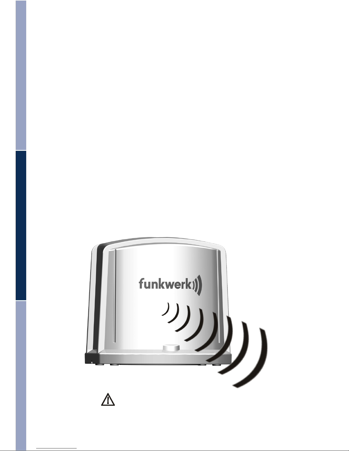
Function Description
The Active Antenna À is suitable for the frequency band range GSM 900, GSM 1800
and UMTS Band I. It supports the transmission process GPRS, HSCSD, EDGE,
UMTS, HSDPA and HSUPA. The connection to the terminal devices is effected using
the mounting UMTS data stick included in the supplies.
The set of an active antenna consists of a basic device [antenna with integrated amplifier], a 15 m long coaxial line, a wall power supply unit and a mounting with
integrated connecting antenna for UMTS data sticks.
The following connections are found on the mounting:
• Plug connector for the connection of the coaxial line to the active
antenna
• 2,1mmbarrelconnectorforsupplyvoltage
The supply voltage required is provided by the enclosed external power supply unit
(8 V, 0,9A).
The active antenna amplifies the UMTS mobile radio signal between the terminal
device and the outdoor antenna in transmission and receiving direction. Furthermore, an additional yield of approx. 7dB is achieved through the directive array. In
the GSM frequency bands the antenna is passive, no boosting is effected.
Note transmission direction!
Deutsch English Türk
Page 5

21
Scope of Supply
À - active antenna with 15 m coaxial line and protection hood
- coupler casing (FAKRA) for coaxial line
- mounting for UMTS data stick
- power supply unit
- mounting bracket
- screw to mount the antenna (3,5mm x 12mm)
- loop clamps
- screws [5x50 STH] and dowels [MU 8x50] for wall mounting
- Operating Manual
À
Ein Unternehmen der Funkwerk AG.
155 8000 0.00
Aktive Antenne
Deutsch English Türk
Page 6

22
Mounting and getting started
Before installation
Please check the supplies for completeness.
Test whether your UMTS data stick fits into the mounting .
The coupler casing included in the supplies is for the safe connection
between coaxial line and the mounting of the UMTS data stick.
ATTENTION! Do not stick the coupler casing onto the coaxial line before
laying work is completed! The coupler casing cannot be removed after
connection!
If the penetration through the wall is planned with, or must have, a small
diameter, please read and observe the mounting steps described in the
following!
Finding out preconditions
To ensure you to get a sound UMTS signal please ask your mobile radio provider
where the nearest transmitter mast is located in the surroundings of your home.
Now lay down the position of the antenna in the outdoor or indoor area.
You have three different installation variants for your active antenna:
Antenna within the house
The active antenna À is positioned within the house at a place at which a sound
UMTS signal is available.
Antenna outside on the house
The active antenna À is mounted to the house wall with the enclosed mounting
bracket .
Antenna on an antenna mast
The active antenna À is mounted to the antenna mast with the enclosed mounting bracket and the loop clamps .
Function Test
1. Find out where the transmitter mast is located in relation to the antenna.
2. Align the antenna approximately; the logo should point to the location of the
transmitter mast. An angular deviation of 30° is possible [when mounting to a
mounting bracket].
3. Now use the software of the mobile ‚phone provider to start up PC or notebook.
4. Connect data stick via USB cable [not included in supplies] with PC or notebook.
5. Connect mounting for UMTS data stick with the power supply unit and
start up.
Deutsch English Türk
Page 7

23
6. Draw the protection cap carefully from the coaxial line.
Note! The protection cap is needed for the wall duct.
7. Connect the HF contact that is now exposed carefully with the middle
connector of the data stick mounting The antenna is in operation when the
green LED of the data stick mounting lights up.
Attention! This connection is not permanent! [only for testing]
8. Now insert the data stick into the mounting , clamp between the mounting
brackets respectively.
9. Check transmitter performance with the provider software. Change the
position of the antenna if necessary.
10. Establish and fix the position of the antenna.
11. Draw the HF contact off the coaxial line carefully from mounting
subtract.
Deutsch English Türk
Page 8

24
Permanent Mounting
Slip the protection cap over the HF contact of the connector as protection
against soilage for possible wall ducts and when laying the cable!
Now plan the laying of the coaxial cable.
Within the house (example without wall duct)
Lay the cable to the place where you want to set up the mounting for the UMTS
data stick. Note that a bend radius of 20 mm may not be undercut.
Strip the protection cap carefully from the coaxial line.
Pus the coupler casing over the HF contact [A] at the end of the coaxial line and
press the magenta catch element tight [B].
Connect the coaxial line with the connection provided for the UMTS stick on the
mounting . The connector of the coaxial line catches audibly.
Connect the power supply unit with the mounting
again.
The LED on the mounting of the UMTS stick lights up
when power is supplied to the antenna and shows you
that the device is ready for operation.
You can now insert the UMTS stick of your mobile radio
provider into the mounting and operate it via a USB
extension cable [not included in the supplies] to your
terminal device [PC, notebook].
B
A
Deutsch English Türk
Page 9

25
Mounting to the Wall
Drill a sufficiently large hole through the house wall. Now mount the mounting bracket near the wall duct with the mounting material found in the supplies.
Then mount the antenna to the mounting bracket.
When mounting to the wall it is possible to adjust the antenna by 30 degrees each
to the left or to the right. Avail yourself of this adjustment possibility to align your
antenna optimally to the transmitter mast.
Now continue as described in the section „Within the house [p. 10].
Holes for
mounting to
the wall.
Holes for
mounting to
the antenna.
Deutsch English Türk
Page 10

26
Mounting to the Antenna Mast
Install the mounting brackets supplied to the bottom of the antenna with the screws supplied.
Now insert the loop clamps through the lateral
holes of the mounting bracket. Tighten the mounting
bracket [incl. antenna] with the loop clamps to
the mast and align it to the transmitter mast.
Note transmission direction!
Now continue as described in the Section „Within the House“ [p. 10].
Trouble Shooting
Problem Possible cause Remedy
Poor reception despite UMTS connection being available
The device is not
switched ON [status LED OFF]
Check all connectors / push plugs into
the power socket
The coupling of the antenna between the UMTS
data stick and the mounting is insufficient
Turn the UMTS data
stick by 180 degrees
around its lateral axis.
Deutsch English Türk
Page 11

27
Technical Specifications
Suitable for : UMTS and GSM900/GSM1800
Supported transmission process : UMTS, HSDPA, HSUPA, GPRS, EDGE,
HSCSD
Operating voltage : 230 V from power supply unit
Maximum transmission power ERP*) : UMTS band 1
approx. 30 dBm [1W] in main radiation
direction
: GSM 900/1800
passive [without amplification] omni directional
Amplification for UMTS band 1 : the amplification is set to precisely balance
the coupling losses of the UMTS data stick
mounting and the losses of the fix connected cable
System amplification : in the main radiation direction approx. 7dB
in the UMTS band 1
Opening angel of the antenna: 60°
Power supply : via wall power supply unit to 230 V~
max. power input: approx. 6W
in standby: approx. 2W
idle: max 0,3W
Wall power supply unit : 8 V / 0,9 A
Operating temperature : -20°C … 70°C
HF Connector : FAKRA
Connector power supply to the
mounting of the UMTS data stick : Hollow plug 2,1
Cable length, type : 15 m, Leoni Dacar 031
Casing : Plastic ASA
*) ERP = effective radiated power
Deutsch English Türk
Page 12

28
Transmission speed
Maximum transmission rates used in practice:
GPRS: 56 kbit/s
EDGE: 220 kbit/s
UMTS: 384 kbit/s
HSUPA: up to 2,000 kbit/s [typical: 1,450 kbit/s]
HSDPA: up to 28,000 kbit/s [typical: 3,600, or 7,200 kbit/s]
Deutsch English Türk
Funkwerk Dabendorf GmbH
Märkische Straße
D-15806 Dabendorf
Telefon +49 (0) 3377 316 - 0
Telefax +49 (0) 3377 316 - 300
eMail info@fwd-online.de
service@fwd-online.de
Internet www.fwd-online.de
Ein Unternehmen der Funkwerk AG.
 Loading...