

Page 1
)
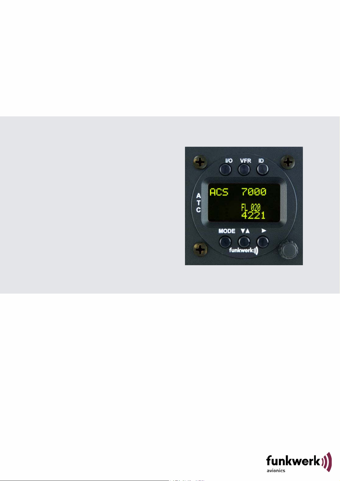
TRT800RT - OLED
Remote Control Unit
P/N 800ATC-H-(Rxx)-(Rxx
Operation and Installation
(Document-No. 03.202.010.71e)
Page 2

Page 3
TRT800RT / P/N 800ATC-H-(Rxx)-(Rxx)
Operation and Installation
Change History
Revision Date Description of Change
1.00 22.10.2012 First Release
List of Service-Bulletins (SB)
Service Bulletins have to be inserted into this manual and to be enlisted
in the following table.
SB No
Rev.
No.
Issue Date
Insertion
Date
Name
Survey of Variants
Part Number Description
P/N 800ATC-H-(R00)–(R00) First version with OLED-Display
2Document-No: 03.202.010.71e / Revision: 1.00
Page 4

TRT800RT / P/N 800ATC-H-(Rxx)-(Rxx)
Operation and Installation
Table of Contents
1 GENERAL................................................................................................... 4
1.1 Symbols ........................................................................................... 4
1.2 Abbreviations ................................................................................... 5
1.3 Customer Support ............................................................................ 6
1.4 Features ........................................................................................... 6
2 OPERATION............................................................................................... 7
2.1 Controls............................................................................................ 7
2.2 Switch ON/OFF ................................................................................ 9
2.3 Display - Indications ....................................................................... 10
2.4 Display-Brightness ......................................................................... 11
2.5 Flight-ID (FID) ................................................................................ 11
2.5.1 Display Flight-ID ................................................................. 12
2.5.2 Configure Flight-ID .............................................................12
2.6 Transponder Mode selection.......................................................... 13
2.7 Squawk-Setting .............................................................................. 13
2.8 VFR – Squawk ............................................................................... 14
2.9 ID – Special Position Identification (SPI): “Squawk Ident” ............. 14
3 INSTALLATION ........................................................................................15
3.1 Notes.............................................................................................. 15
3.2 Scope of Delivery ........................................................................... 15
3.3 Unpacking and Inspecting of the Equipment ................................. 15
3.4 Mounting ........................................................................................ 16
3.5 Equipment Connections ................................................................. 17
3.5.1 Electrical Connections........................................................ 17
3.6 Wiring ............................................................................................. 17
3.6.1 Conductor Cross Section.................................................... 17
3.6.2 Pin Assignment................................................................... 17
3.7 Post-Installation Check ..................................................................18
3.8 Drawings ........................................................................................ 19
3.8.1 Dimensions......................................................................... 19
3.8.2 Mounting Advices ............................................................... 19
4 APPENDIX................................................................................................ 20
4.1 Technical Data ............................................................................... 20
4.2 Environmental Conditions .............................................................. 21
3 Document-No: 03.202.010.71e / Revision: 1.00
Page 5
TRT800RT / P/N 800ATC-H-(Rxx)-(Rxx)
Operation and Installation
1 GENERAL
This manual contains information about the physical, mechanical and
electrical characteristics and about installation and operation of the
transponder remote control TRT800RT.
1.1 Symbols
Advices whose non-observance can cause radiation
damage to the human body or ignition of combustible
materials
Advices whose non-observance can cause damage to the
device or other parts of the equipment.
Supplementary information
4Document-No: 03.202.010.71e / Revision: 1.00
Page 6

TRT800RT / P/N 800ATC-H-(Rxx)-(Rxx)
Operation and Installation
1.2 Abbreviations
Abb. Meaning Explanation
FID Flight ID Flight plan number or if not assigned
registration number of aircraft
SPI Special Position
Identification
Activation on request by controllers
„Squawk Ident“, transmits SPI Pulse
for 18 seconds, which highlights the
respective traffic item on the
controllers radar screen
5 Document-No: 03.202.010.71e / Revision: 1.00
Page 7
TRT800RT / P/N 800ATC-H-(Rxx)-(Rxx)
Operation and Installation
1.3 Customer Support
In order to facilitate a rapid handling of return shipments, please follow
the instructions of the input guide „Reshipment RMA“ provided at the
Service-Area within the Funkwerk Avionics web portal www.funkwerk-
avionics.com.
Any suggestions for improvement of our manuals are
welcome. Contact: service@funkwerk-avionics.com
.
Informations on software updates are available at Funkwerk
Avionics
1.4 Features
Remote control and indication of all transponder settings/data during
standard operation (e.g. squawk code, operation mode, altitude etc).
Ideal for tandem seated aircraft:
Use of transponder still possible without activation of remote control
Automatic deactivation of remote control on deactivation of
transponder
6Document-No: 03.202.010.71e / Revision: 1.00
Page 8
TRT800RT / P/N 800ATC-H-(Rxx)-(Rxx)
q
q
q
Operation and Installation
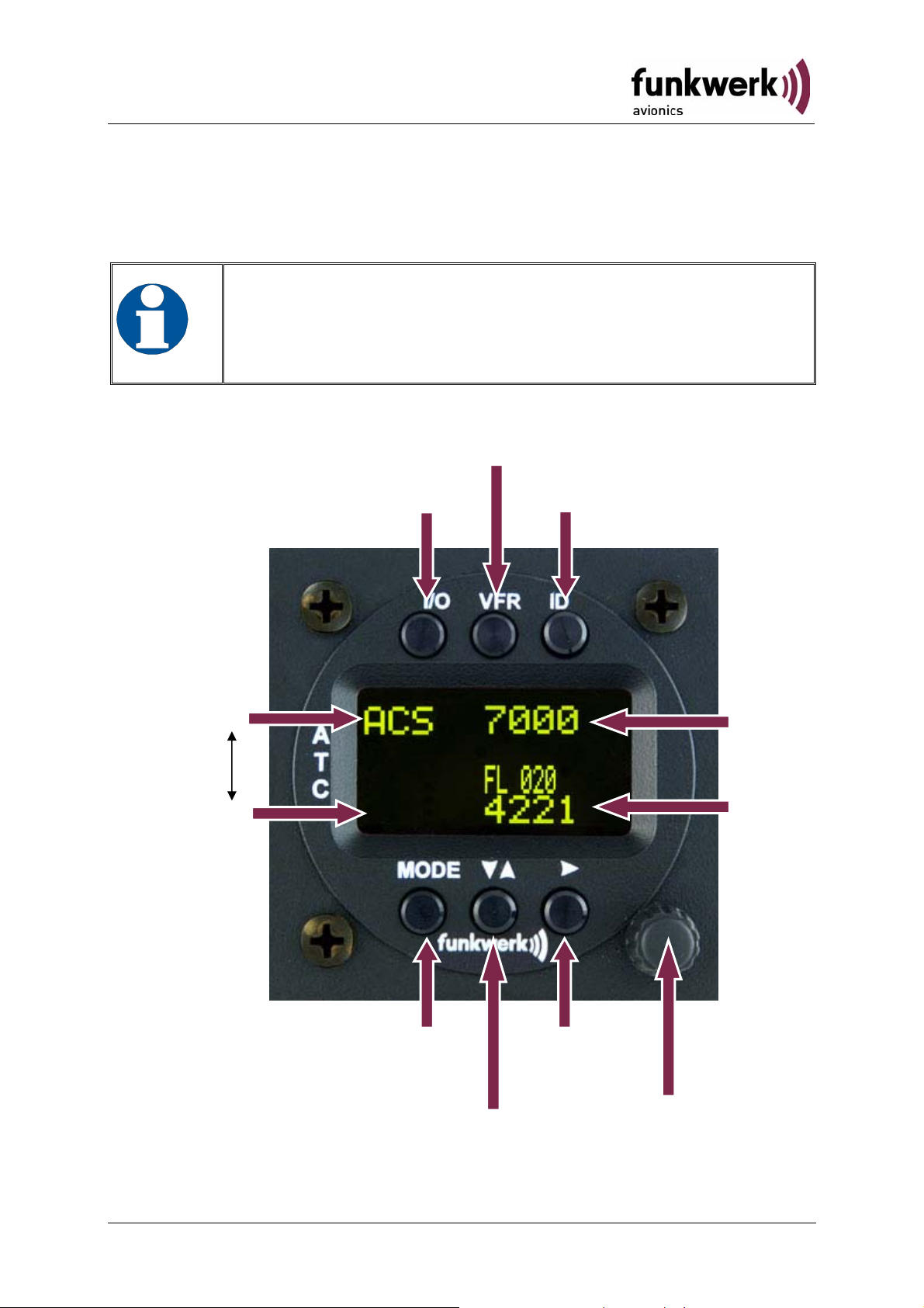
2 OPERATION
2.1 Controls
If remote unit settings are inconsistent with transponder
settings as a result of short time transmission problem
(e.g. simultaneous user inputs) remote unit settings will be
reverted to current transponder setting.
Activate/
deactivate VFR
active
Operation
Mode
standby
ON / OFF
„Squawk Ident“
Active
uawk
S
Standby
uawk
S
Select Operation
Change
Active Ù Standby
S
7 Document-No: 03.202.010.71e / Revision: 1.00
Cursor
adjustment
uawk
Rotary Knob
for adjusting values
at the cursor
position
Page 9

TRT800RT / P/N 800ATC-H-(Rxx)-(Rxx)
Operation and Installation
►►Switch ON press button for approx. 0,5 s
I/O ON/OFF
Switch OFF press button for approx. 3 s
►
activate/deactivate VFR Squawk
(press shortly)
VFR VFR
store active Squawk as VFR/VFRW-Squawk
►
(press button 3 s, →2.8)
►►change between active and standby-Squawk
works as cursor back button (opposite function
▲▼ CHANGE
of the cursor button) during entering values and
also for navigating backwards through the
configuration menu (→Fehler! Verweisquelle
konnte nicht gefunden werden.)
►
„Squawk Ident“, sends Ident marking (SPI) for
18 s (→ 2.9)
ID IDENT
►
Enter Flight-ID (FID) setup (in standby mode,
press button for approx. 5s)
► Select transponder operational mode (→ 2.6)
MODE MODE
► Set position of Cursor
► CURSOR
► Adjust/Enter values at current cursor position,
Rotary
select options; set standby Squawk (→ 2.7)
Knob
8Document-No: 03.202.010.71e / Revision: 1.00
Page 10

TRT800RT / P/N 800ATC-H-(Rxx)-(Rxx)
S
000
Operation and Installation
2.2 Switch ON/OFF
Switch ON: press I/O for 0.5 s
Switch OFF: press
2.2.1 Display information after power up
After turning-on the display appears as follows (example):
I/O for 3 s
Device Name
TRT800RT.
V1.1
2000
FL 030
TBY 7
Software Version
Connection to transponder
is successfully established
Transponder
not
detected
9 Document-No: 03.202.010.71e / Revision: 1.00
Transponder is not found /
data transmission failed
Page 11

TRT800RT / P/N 800ATC-H-(Rxx)-(Rxx)
A
Operation and Installation
2.3 Display - Indications
Operational Mode:
ctive
ACS
SPI indicator
Operational Mode
Standby
Value Meaning Remarks
7000 active Squawk
2000 Standby Squawk Could be changed with active
PLL/TRX/
IDT FL 030
STBY
Lock out
indication
DC | BAT/DIM
Error
indications
Reply
indication
7000
2000
Passive
Squawk
Squawk by pressing
Active Squawk
Backlight setup
Low battery ind.
Flight level
F
GND switch
status
▲▼
FL 010
FLerr
ACS Operational Mode
IDT transmits Ident-Marking (SPI) ID („Squawk Ident“) has been
| Transponder is locked by a
F
G
Flight Level
Invalid altitude measuring
(STBY, A-S, ACS, AC, A)
Transponder replies
on Mode-S, Mode-A or ModeC interrogations
ground station and will be
directly addressed
in-flight
on-ground
Flight Level (in 100 ft steps)
Modes see section 2.6
pressed – active for 18 s
No indication on ADSB and
squitter transmission
Lock Information (indicated
below the diamond)
Ground-Switch-Info
(if available)
10Document-No: 03.202.010.71e / Revision: 1.00
Page 12

TRT800RT / P/N 800ATC-H-(Rxx)-(Rxx)
Operation and Installation
Error indicators
PLL PLL Error Internal Error
TRX Transmit Failure Check antenna and wiring
DC Low internal voltage Internal error
FPG FPGA-Failure Internal error
BAT Battery Power too low maybe battery/generator fault
Note: Short time indication symbols (e.g. lock-out indication or reply
indication) are displayed/cleared in different time interval or delayed in
comparison with TRT800H screen.
2.4 Display-Brightness
In active mode (not standby) press ► for 2 s
Display indicates “DIM” Æ Adjust brightness (DIM) with rotary knob
Return to normal operation: press
► or wait 5 s.
2.5 Flight-ID (FID)
The FID is an identifier required by Mode-S Operation. During future
application of flight plans a FID could be assigned on a per flight basis. If
no FID is assigned (today’s normal case) the registration marking of the
aircraft should be used as FID. The FID should not
blanks.
contain dashes or
11 Document-No: 03.202.010.71e / Revision: 1.00
Page 13

TRT800RT / P/N 800ATC-H-(Rxx)-(Rxx)
_ _
_
Operation and Installation
2.5.1 Display Flight-ID
Press
Press and hold ID while a counter is shown beside the active squawk.
During a few seconds Flight Identification is displayed
MODE (repeatedly) until „STBY“ appears
FID 02
A B C D E F G H
2.5.2 Configure Flight-ID
Press
Press and hold ID while a counter is shown beside the active squawk.
Release
CHANGE FID
MODE (repeatedly) until „STBY“ appears
ID when “CHANGE FID” is displayed
_ _ _ _ _
A B C D E F G H
exit
Enter Flight-Id with cursor button ► and rotary knob
Enter FID left-aligned, without any blanks or dashes (!)
12345621DEFAV for the marking D-EFAV. The last
remaining digits shall be filled with blanks
Press
12Document-No: 03.202.010.71e / Revision: 1.00
MODE to save and return to STBY
After FID is changed: Check that new FID is accepted and
correctly set
, e.g.
Page 14

TRT800RT / P/N 800ATC-H-(Rxx)-(Rxx)
Operation and Installation
2.6 Transponder Mode selection
Press MODE (repeatedly) to select from following Modes:
• STBY Æ „Standby“
Transponder does not respond to any interrogation. Squitter and
ADS-B output is not active.
• ACS Æ„Mode A+C+S“
Standard condition; transponder responds to mode A, C and S
interrogations.
• A-S Æ „Mode A+S, no C“
Altitude is not transmitted (neither on C nor on S requests). All
other Mode-S data as well as Mode-A replies are transmitted.
If no 24-bit address (AA) was defined or entered as “000000“ the
transponder works as Mode A-C transponder, in that case the
following Modes are possible apart from Standby:
• AC- Æ „Mode A+C“
Transponder replies only on Mode A and Mode-C interrogations.
• A-- Æ „Mode A“
Transponder replies only on Mode A interrogations.
In STBY (Standby) mode, all transponder transmissions
are disabled completely! Therefore, the transponder is not
visible in this mode to air traffic control or the anti-collision
systems onboard other aircrafts.
Never use the STBY mode in flight
unless you are requested
to do so by air traffic control. Always remember to put the
transponder in active mode prior to take off!
2.7 Squawk-Setting
The active Squawk is displayed in the upper line, while the standby
Squawk is presented at the lower line.
Setting the Standby Squawk:
• Press
► to set the cursor („^“), turn rotary knob to set numbers
of the standby Squawk.
• Press
▼▲ to activate the Standby Squawk (this moves the
current active Squawk into Standby)
13 Document-No: 03.202.010.71e / Revision: 1.00
Page 15

TRT800RT / P/N 800ATC-H-(Rxx)-(Rxx)
Operation and Installation
2.8 VFR – Squawk
The transponder features a user-defined squawk code for VFR-flight
(factory setting: 7000):
• Activate VFR-Squawk:
Press
moved into Standby but not visible because the indication of the
Standby Squawk is overlapped by „VFR“
• Display Standby Squawk:
Press
Squawk remains active!)
Example:
FL 030
STBY
• Now the Standby Squawk can be adjusted by using the
knob and activated with
VFR („VFR“ is indicated), now the active Squawk is
VFR or ▼▲ or use the rotary knob (the VFR-
4700
5600
FL 030
STBY
VFR VFR
▼▲.
7000
VFR
FL 030
STBY
7000
4700
rotary
• In order to store the current active Squawk as new VFR-Squawk
(replacing the factory setting 7000):
Press and hold
releasing the button „VFR“ is shown
VFR until an „S“ is indicated (approx. 3 s); after
2.9 ID – Special Position Identification (SPI): “Squawk
Ident”
Press ID to activate transmission of the special position identification
pulse with every reply within 18 seconds; “IDT” appears on the display
By pressing
transmitted with every reply within 18 seconds, which causes an
accented marking on the Controller’s screen. The „Special Position
Identification“ has to be activated after the „Squawk Ident“ request of the
Controller.
14Document-No: 03.202.010.71e / Revision: 1.00
ID a special position identification pulse (SPI) is
Page 16

TRT800RT / P/N 800ATC-H-(Rxx)-(Rxx)
Operation and Installation
3 INSTALLATION
3.1 Notes
The following suggestions should be considered before installing.
The assigned installation company will supply wiring. For diagrams refer
to 3.6 Wiring.
Remote Header and cables shall be installed according to „FAA AC-
143.13-2A Acceptable Methods, Techniques and Practices – Aircraft
Alterations“ and the appropriate manufacturer’s instructions.
3.2 Scope of Delivery
Item name / number Description
TRT800RT Remote Header
TRT800H-Remote Control Unit
ATR600RTK3 Connector
M4X8ZSW
(3 pieces)
03.202.010.71e Manual „Operation and Installation“
EASA Form 1
screw for panels up to 5 mm thickness
3.3 Unpacking and Inspecting of the Equipment
Carefully unpack the equipment and inspect for transport damages. If a
damage claim has to be filed, save the shipping container and all
packing materials as evidence to your claim.
For storage or reshipment the original packaging should be
used.
15 Document-No: 03.202.010.71e / Revision: 1.00
Page 17

TRT800RT / P/N 800ATC-H-(Rxx)-(Rxx)
Operation and Installation
3.4 Mounting
• In cooperation with a maintenance shop, location and kind of the
installation are specified. The maintenance shop can supply all
cables. Suitable sets of cables are available from Funkwerk
Avionics GmbH.
• Select a position away from heat sources. Care for adequate
convection cooling.
• Leave sufficient space for the installation of cables and connectors.
• Avoid sharp bends and wiring close to control cables.
• Leave sufficient lead length for inspection or repair of the wiring of
the connector (containing the memory), so that when the mounting
hardware for the rear connectors is removed, the assembly may be
pulled forward several inches.
• Bend the harness at the rear connectors to inhibit water droplets
(formed due to condensation) from collecting in the connector.
• For mounting details/drawing refer to chapter 3.8.2 Mounting
Advices.
16Document-No: 03.202.010.71e / Revision: 1.00
Page 18

TRT800RT / P/N 800ATC-H-(Rxx)-(Rxx)
Operation and Installation
3.5 Equipment Connections
3.5.1 Electrical Connections
One 9 pin D-SUB miniature connector includes all electrical connections.
When powering the remote control not by the output of the
switched power output of the remote controlled device but
directly by the aircraft’s power supply, the power input line
(+UB) must be equipped with an external fuse (1Amp./slow).
3.6 Wiring
3.6.1 Conductor Cross Section
Power Supply (Power, GND): AWG20 (0,62 mm²)
Signals: AWG22 (0,38 mm²)
The conductors must be approved for aircraft use. RX and TX should be
shielded individually, or at least be pair-twisted and shielded together.
3.6.2 Pin Assignment
Pin Signal Remarks
1 GND (Data) -
2 Data TX Output
3 -
4 Light Input
5 UB+ Power input
6 GND (Data)
7 Data RX Input
8 - -
9 UB+
(1)
UB+: Can be connected to switched power output of
Power input
(1)
transponder.
17 Document-No: 03.202.010.71e / Revision: 1.00
Page 19

TRT800RT / P/N 800ATC-H-(Rxx)-(Rxx)
Operation and Installation
3.7 Post-Installation Check
A certified maintenance shop must verify proper operation of
remote control header”.
All steering and control functions of the aircraft are to be examined, in
order to exclude disturbances by the wiring.
18Document-No: 03.202.010.71e / Revision: 1.00
Page 20

TRT800RT / P/N 800ATC-H-(Rxx)-(Rxx)
g
Operation and Installation
3.8 Drawings
3.8.1 Dimensions
3.8.2 Mounting Advices
Fixing clips (spring)
left / ri
ht
Connector (plug) has to be clamped with both spring locks.
New screws may be turned in more than max. 15mm into
the device – even if no hard limit is noticeable.
19 Document-No: 03.202.010.71e / Revision: 1.00
Page 21

TRT800RT / P/N 800ATC-H-(Rxx)-(Rxx)
Operation and Installation
4 APPENDIX
4.1 Technical Data
Compliance CS-ETSO-2C112a
EASA.21O.269
Applicable Documents CS-ETSO-2C112a
EUROCAE ED-73B Class 1 Level 2es
EUROCAE ED-26
RTCA DO-160D
RTCA DO-178B Software-Level D
Temperature Ranges
Operation -20 °C to +55 °C; for 30 min +70°C
Storage -55 °C to +85 °C
Altitude Range ≤ 35 000 ft
Shock 6 G Operation
20 G crash safety
Environmental Categories RTCA DO-160D Env.Cat.:
[C1Z]CAA[SM]XXXXXXZBAAA[TT]M[B3F3]
XXA
Power Supply 13,8 VDC (10 VDC .. 16 VDC)
0,06 A @ 13,8 VDC (typ.)
600 mW (max)
Fuse External 1A-slow-blow fuse
Mounting Panel cut-out d=57,5 mm
Weight 0,2 kg (0.43 lbs.)
20Document-No: 03.202.010.71e / Revision: 1.00
Page 22

TRT800RT / P/N 800ATC-H-(Rxx)-(Rxx)
Operation and Installation
4.2 Environmental Conditions
Characteristic DO–160D Section Cat. Condition
Temperature / Altitude 4.0
Low ground survival
4.5.1 – 55°C
temperature
Low operating temperature 4.5.1 – 20°C
High ground survival
C1
4.5.2 + 85°C
Temperature
High Short-time Operating
4.5.2 + 70°C
Temperature
High Operating Temperature 4.5.3
+ 55°C
No auxiliary cooling
In-Flight Loss of Cooling 4.5.4 Z
required
Altitude 4.6.1 C1 35 000 ft
2°C change rate
Temperature Variation 5.0 C
minimum per minute
Humidity 6.0 A
6 G operational shocks
20 G Crash Safety
Shock 7.0 A
Test Type R in all 6
directions
Vibration 8.0 S Vibration Curve M
Explosion Proofness 9.0 X No test required
Water Proofness 10.0 X No test required
Fluids Susceptibilities 11.0 X No test required
Sand and Dust 12.0 X No test required
Fungus Resistance 13.0 X No test required
Salt Spray 14.0 X No test required
Magnetic Effect 15.0 Z Less than 0,3 m
Power Input (DC) 16.0 B
Voltage Spike Conducted 17.0 A
Audio Frequency Conducted
18.0 A
Susceptibility
21 Document-No: 03.202.010.71e / Revision: 1.00
Page 23

TRT800RT / P/N 800ATC-H-(Rxx)-(Rxx)
Operation and Installation
Characteristic DO–160D Section Cat. Condition
Induced Signal Susceptibility 19.0 A
Radio Frequency
20.0 TT
Susceptibility
Emission of RF Energy 21.0 M
Lightning Induced Transient
22.0 B3F3
Susceptibility
Lightning Direct Effects 23.0 X No test required
Icing 24.0 X No test required
Electrostatic Discharge (ESD) 25.0 A
22Document-No: 03.202.010.71e / Revision: 1.00
Page 24

TRT800RT / P/N 800ATC-H-(Rxx)-(Rxx)
Operation and Installation
Notes:
23 Document-No: 03.202.010.71e / Revision: 1.00
Page 25

Funkwerk Avionics GmbH
Heinz-Strachowitz-Str. 4
DE-86807 Buchloe
Germany
phone.: +49-8241 80066 0
fax.: +49-8241 80066 99
E-mail:
service@funkwerk-avionics.com
www.funkwerk-avionics.com
 Loading...