

Page 1
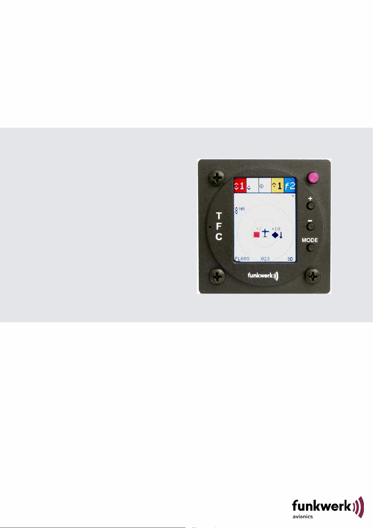
TM250
Traffic Monitor
P/N 250TM-(xxx)-(xxx)
Operation and
Installation
(Document-No. 03.310.010.71e)
Page 2

Page 3

TM250 / P/N 250TM-(xxx)-(xxx)
Operation and Installation
List of Changes
Revision Date Change description
1.00 11.06.2009 First issue
1.01 21.07.2009 Visual Alerting
1.02 29.07.2009 Manual Setting of the ICAO 24-bit address,
Software-Update by users
1.03 17.08.2009 Added Wiring Diagram (4.2)
1.04 30.07.2010 New Human Machine Interface
Added information on connectors
1.05 28.01.2011 FLARM® Target Counter, automatic detection
of external FLARM® device
1.06 31.03.2011 Pictures updates (2.1)
2.00 04.04.2012 Software 2.0 with Mode AC- functionality
2.01 01.04.2013 CE Declaration of Conformity adapted
2.10 24.06.2013 Software 2.1 - additional traffic protocol
List of Service Bulletins (SB)
Service bulletins are to be inserted in the manual and to be recorded in
the table.
SB Number
Rev.
Nr.
Issue date
Date of
Insertion
Name
Device overview
Article number Description
P/N 250TM-(000)-(000) Basic variant
P/N 250TM-(100)-(100) New HMI, Connection for external
displays
2Document No.: 03.310.010.71e / Revision: 2.10
Page 4

TM250 / P/N 250TM-(xxx)-(xxx)
Operation and Installation
Table of Contents
1 Introduction ....................................................................................... 5
1.1
Symbols ........................................................................................... 5
1.2
Customer Service ............................................................................. 5
1.3
Device Overview .............................................................................. 6
2 Operation .......................................................................................... 9
2.1
Operation Controls ........................................................................... 9
2.2
Switching On/Off ............................................................................ 10
2.3
Traffic Display ................................................................................ 10
2.3.1 Layout of the Traffic View .......................................................... 10
2.3.2 Symbols and Representations of the Traffic View ..................... 11
2.4
Configuration Page ........................................................................ 14
2.4.1 Audio ......................................................................................... 14
2.4.2 FLARM® .................................................................................... 16
2.4.3 Mode S ...................................................................................... 16
2.4.4 Mode C ...................................................................................... 16
2.4.5 Display ...................................................................................... 17
2.4.6 Filter .......................................................................................... 17
2.4.7 Traffic Transmit - Tfc Tx ............................................................ 18
2.4.8 Demo ......................................................................................... 19
2.5
ICAO Configuration Page ............................................................... 20
2.6
Information Page ............................................................................ 22
2.7
Output of traffic data ....................................................................... 23
2.8
Software Update ............................................................................ 23
3 Installation ....................................................................................... 24
3.1
Unpacking and Inspection .............................................................. 24
3.2
Scope of Delivery ........................................................................... 24
3.3
Mounting ........................................................................................ 25
3.4
Connectors ..................................................................................... 26
3.4.1 GPS Antenna ............................................................................ 26
3.4.2 1090MHz / FLARM® Antenna .................................................... 26
3.4.3 USB ........................................................................................... 27
3.4.4 Power / RS-232 ......................................................................... 27
3.5
Device Dimensions ........................................................................ 29
3.5.1 Housing ..................................................................................... 29
3.5.2 Installation Tips ......................................................................... 30
3.6
Post-installation Checks ................................................................. 30
3.7
Accessories .................................................................................... 30
3 Document No.: 03.310.010.71e / Revision: 2.10
Page 5

TM250 / P/N 250TM-(xxx)-(xxx)
Operation and Installation
4 APPENDICES ................................................................................. 31
4.1
Technical Data ............................................................................... 31
4.2
Wiring Diagram .............................................................................. 32
4.2.1 Cable Harness for TRT-Serie (XPDR) ...................................... 32
4.2.2 Cable Harness for OEM-device (XPDR) .................................. 33
4.3
Threat Classifications – Zone Division ........................................... 34
4Document No.: 03.310.010.71e / Revision: 2.10
Page 6
TM250 / P/N 250TM-(xxx)-(xxx)
Vital information that if not followed may cause damage in
the device or in other parts of equipment or may have a
manuals are
Information about software updates is available from
Operation and Installation
1 INTRODUCTION
This manual contains information about the physical, mechanical and
electric characteristics and instructions on installation and operation of
the traffic display TM250.
1.1 Symbols
negative impact on the correct function of the device.
Information
1.2 Customer Service
For fast handling of returns please follow the instructions on the form for
complaints and returns provided in the service area of the Funkwerk
Avionics website www.funkwerk-avionics.com.
Suggestions for the improvement of our
welcome. Contact: service@funkwerk-avionics.com.
Funkwerk Avionics.
5 Document No.: 03.310.010.71e / Revision: 2.10
Page 7

TM250 / P/N 250TM-(xxx)-(xxx)
Operation and Installation
1.3 Device Overview
The traffic display TM250 by Funkwerk Avionics GmbH is aimed at
supporting air space surveillance for General Aviation. It integrates
Mode S, ADS-B, and FLARM ®-Detection in one single device for
cockpit installation.
ADS-B, Mode S and Mode AC
ADS-B (Automatic Dependent Surveillance – Broadcast) means that
airplanes whose Mode S transponder is coupled with a GPS receiver
emit their position data on the frequency 1090 MHz. This data can be
received by all airspace users in a vicinity of up to approx. 150 NM.
These ADS-B transmissions from other airplanes are decoded by the
built-in Mode S receiver in the TM250. The display of the TM250
indicates the relative position of these airplanes as well as their vertical
movement direction. This allows a quick assessment of the traffic
situation.
Today, the majority of Air Transport airplanes are equipped with ADS-B
capable systems. Because General Aviation still has a relatively low
degree of ADS-B equipage, airplanes whose transponders do not send
out ADS-B signals are also detected by the TM250. This is achieved
through evaluation of the field strength of the Mode S and Mode AC
signals. In this case, the proximity of such airplanes is signalled by the
TM250 graphically and acoustically. However, a representation of
direction or position of these airplanes is not possible.
The TM250 includes a built-in GPS receiver and can transmit its position
data via an additional serial interface to an ADS-B capable Mode S
transponder (such as the TRT800A/H). Such an installation forms a
complete ADS-B system that can receive and transmit position data
through ADS-B and contributes therefore actively to flight safety.
FLARM®
Nowadays, numerous glider aircraft are equipped with so-called FLARM®
systems for collision avoidance. Via a serial interface, an external
FLARM® receiver can be connected to the TM250 which then allows
indicating the position and movement direction of these airplanes on the
display of the TM250.
6Document No.: 03.310.010.71e / Revision: 2.10
Page 8

TM250 / P/N 250TM-(xxx)-(xxx)
alert
), in order to avoid
This does not impact the display of
Operation and Installation
In case an external FLARM® is connected, the FLARM®
will automatically be disabled (see 2.4.2
permanent alerting.
FLARM® targets. FLARM® targets will still be displayed.
If the aircraft does not carry such a FLARM® receiver connected to the
TM250, other gliders nearby that have a FLARM® transmitter can still
being detected and indicated on the TM250 graphically and acoustically.
This is achieved through a raw, non-directional detection of the signal
strength of a nearby FLARM® transmitter inside the TM250. In this case,
however, it is not possible to indicate the direction, distance, altitude, or
position of such targets. Also, no transmission to other gliders occurs.
For traffic display and warning, four different types of targets are
distinguished depending on the respective equipment of these aircraft.
1. FLARM® targets
Aircraft, particularly gliders, with a FLARM® system: As long as no
external FLARM® receiver is connected to the TM250, the recognition of
the FLARM® equipped airplanes is based merely on the detection of the
signals, and will be shown in the counter, but not on the “map”.
Due to their low radio transmission power, FLARM® targets can only be
detected in smaller distances than the other target types.
2. Mode S targets
Aircraft with a Mode S transponder without ADS-B "out" function (not
"extended squitter" capable): The Mode S Transponder sends out the
ICAO 24bit address that allows identifying the transmitter. A rough
estimate of distance and approach rate of each transponder is
determined by measuring the field strength of these transmissions.
3. Mode AC targets
Aircraft with non-Mode-S-capable (older) transponder: The transponder-
transmissions contain either the altitude (Mode C) or the Squawk
(Mode A). It is technically not possible to always distinguish between
these two transmissions – for safety reasons, in these cases the
information is always interpreted as altitude, what may lead to
unnecessary warnings. As additionally the AC transmissions do not
contain the 24bit address of the Mode S signal, it is not impossible, that
one and the same aircraft, due to transmitting both Mode S and
7 Document No.: 03.310.010.71e / Revision: 2.10
Page 9
TM250 / P/N 250TM-(xxx)-(xxx)
Some aircraft will not be detected at all, as they have neither
, due to the
a
n warning
system and may only be used as supportive means for
the surrounding
airspace and to comply with all applicable rules and
Operation and Installation
Mode AC, is detected multiple times. A rough estimate of distance and
approach rate of each transponder is determined by measuring the field
strength of these transmissions.
4. ADS-B targets
For aircraft with a Mode S transponder that is ADS-B "out" capable: The
position information transmitted by these aircraft can be used directly for
the traffic display and for determination of dangerous proximities.
a transponder nor a FLARM® device activated.
Other aircraft will be detected multiple times
manifold signal evaluations – the theoretical maximum is
four-time detection (ADS-B, Mode S, Mode AC, FLARM®).
This device is not a certified anti-collisio
airspace observation.
The pilot is still obliged to observe
regulations for safe flight operations..
8Document No.: 03.310.010.71e / Revision: 2.10
Page 10
TM250 / P/N 250TM-(xxx)-(xxx)
view radius
between views
Operation and Installation
2 OPERATION
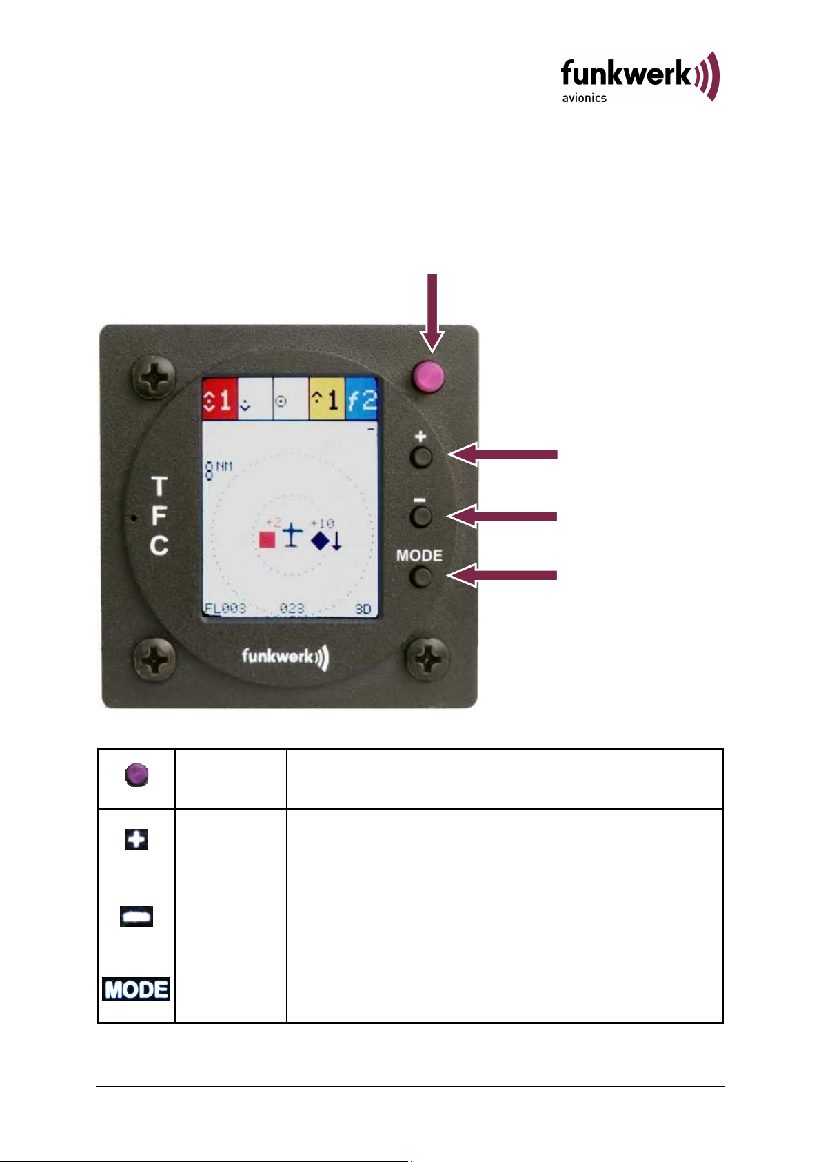
2.1 Operation Controls
ON/OFF
Increase of the
Decrease of the
view radius
Change
ON/OFF Power Switch
1. TFC view – increase of the view radius
PLUS
2. SETTINGS – modification of values
1. TFC view – decrease of the view radius
9 Document No.: 03.310.010.71e / Revision: 2.10
MINUS
MODE
2. SETTINGS – navigation through the menu
(down)
Change between the views TFC, SETTINGS,
and INFO
Page 11
TM250 / P/N 250TM-(xxx)-(xxx)
Operation and Installation
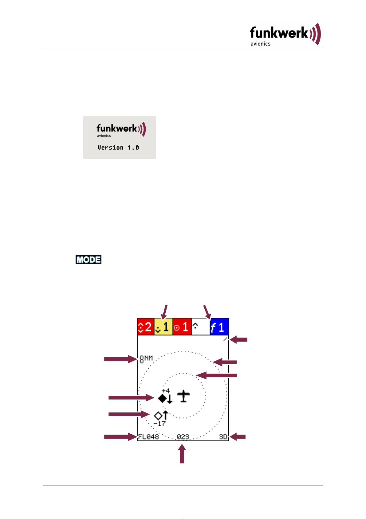
2.2 Switching On/Off
The device is turned on with the ON/OFF switch. After switching it on,
the following indication is shown:
Company logo
(Example)
This announcement can be skipped over by pressing any key.
Software-Version
2.3 Traffic Display
After the initial start screen, the display changes to traffic view (TFC).
Other available views are the configuration pages (SETTINGS) and the
information page (INFO). Changing between these four views is done
with the key.
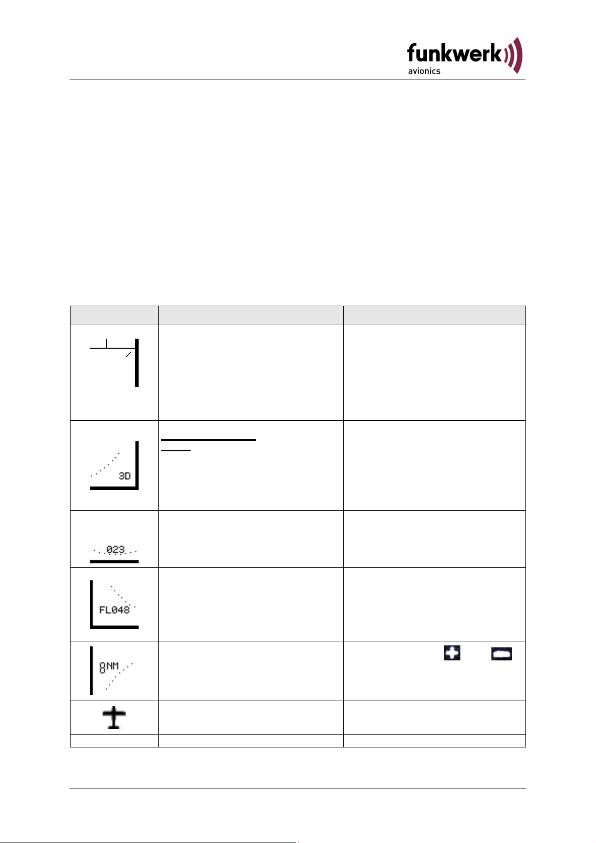
2.3.1 Layout of the Traffic View
(Mode S, Mode AC, FLARM)
Viewing radius
(Zoom level)
Visual Alarm
Reception of
traffic data
Range circles
Traffic items
(ADS-B+FLARM)
Flight level
GPS reception
10Document No.: 03.310.010.71e / Revision: 2.10
GPS Track
Page 12
TM250 / P/N 250TM-(xxx)-(xxx)
Operation and Installation
Around the own aircraft symbol there are two range circles that are
always arranged in a way that the external one corresponds to the
selected viewing radius. The inner range circle corresponds to half of the
selected viewing radius.
In the lower line, the current flight level, GPS track and the quality of
GPS reception are indicated.
Other details of various representations and symbols are described in
the following section.
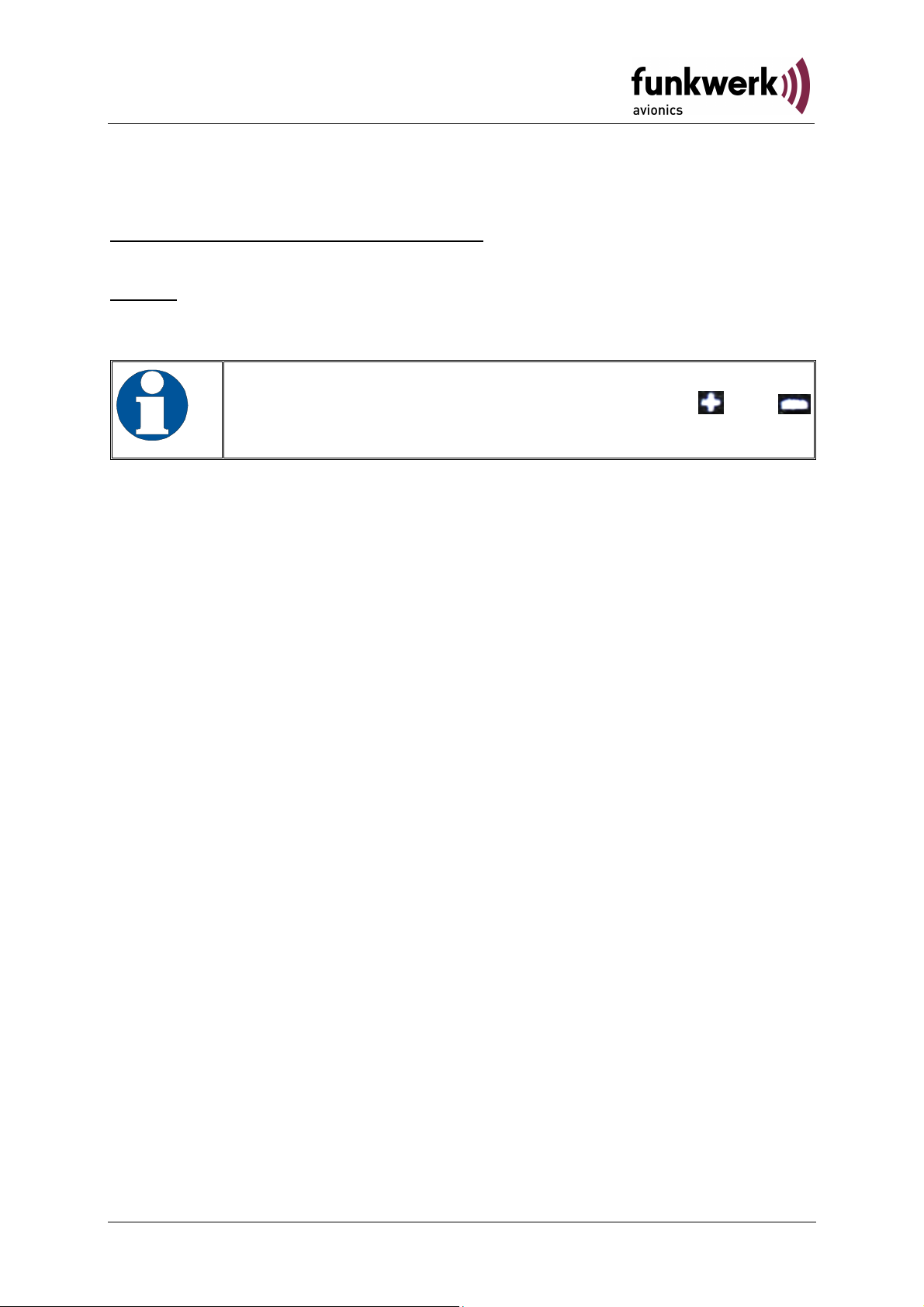
2.3.2 Symbols and Representations of the Traffic View
Indication Explanation Remarks
Rotating Bar
Reception of traffic data
(FLARM®, Mode S or ADSB)
GPS reception:
GPS: no GPS reception
2D: only horizontal position
3D: horizontal position and
altitude
GPS track
Flight level
"NoFL" indicates that only
GPS altitude is available
Shown in the upper right
corner of the display
Shown in the lower right
corner of the display
Current track as determined
by the internal GPS module
Based on barometric
altitude (as transmitted by
the own aircraft transponder
in the ADS-B report)
Adjustable with and .
Viewing radius (zoom level)
11 Document No.: 03.310.010.71e / Revision: 2.10
Symbol of own airplane
Possible values are 1 NM,
2 NM, 4 NM, and 8 NM.
Page 13

TM250 / P/N 250TM-(xxx)-(xxx)
approach
Operation and Installation
Indication Explanation Remarks
External FLARM® device
detected
The FLARM® targets will be
displayed in the “map” view
At least one FLARM®
Number of FLARM® signals
detected
transmitter is nearby (if no
external FLARM® device
has been connected)
Number of Mode S and of
Mode AC alarms
without altitude information
The measured field strength
exceeds threshold values
Number of Mode S and of
Mode AC alarms
below the own altitude
The small triangle indicates
These targets are 300 ft to
1200 ft below
possible multiple detection
Number of Mode S and of
Mode AC alarms
in the same altitude
The small triangle indicates
The relative altitude
distance of these targets is
less than 300 ft
possible multiple detection
Number of Mode S and of
Mode AC alarms
above the own aircraft
The small triangle indicates
possible multiple detection
Traffic symbol without threat
potential
Traffic symbol with direction
indication without threat
potential
Traffic symbol with
alarm
12Document No.: 03.310.010.71e / Revision: 2.10
These targets are
300 ft to 1200 ft above
For definition see 4.3
Page 14

TM250 / P/N 250TM-(xxx)-(xxx)
B) the absolute
Operation and Installation
Indication Explanation Remarks
Direction indicator with
For definition see Fehler!
approach alarm
Verweisquelle konnte
nicht gefunden werden.
Traffic symbol with potential
For definition see 4.3
collision threat
For definition see Fehler!
Direction indicator with
potential collision threat
Verweisquelle konnte
nicht gefunden werden.
Traffic symbol with collision
For definition see 4.3
threat - action required
Direction indicator with
collision threat -
action required
For definition see Fehler!
Verweisquelle konnte
nicht gefunden werden.
Symbol for ADS-B and
FLARM® targets (if external
FLARM® is connected):
Traffic objects whose
position is shown in relation
to own position
In addition, the relative
altitude (flight level
difference) and a trend
arrow for climbing and
descending are indicated.
If own barometric altitude
cannot be determined
(because own Mode S
Transponder does not
support ADSflight level is indicated
instead of the relative flight
level.
Depending on whether the
traffic object is above or
below own aircraft, the
relative altitude will be
shown above or below the
symbol.
If the target's climb or
descent rate exceeds
500 ft/min an accordingly
directed trend arrow is
shown next to the symbol.
13 Document No.: 03.310.010.71e / Revision: 2.10
Page 15

TM250 / P/N 250TM-(xxx)-(xxx)
Operation and Installation
2.4 Configuration Page
The configuration view may be selected by the use of the Button.
The desired menu item can then be selected by one or multiple presses
of the minus key . Selection goes repeatedly from top to bottom. The
blue background indicates the active menu item that can be adjusted
with the
key. More details on each menu item can be found in the
following segments.
2.4.1 Audio
In addition to the visual warnings audio alerts can also be raised. The
following settings for when and how audio alerts will be raised are
offered:
once ........... For each traffic object, an audio alert is raised only once
when it is recognized as a threat
repeat ......... The audio alert continues as long as the target poses a
threat or the user confirms (and thus silences) the alarm with
the
or
key. Any alert needs to be confirmed
separately. Depending on the threat level the audio alerts
will be repeated every 4 seconds for the approach alarm,
every 2 seconds for a potential collision threat and once per
second for an active collision threat.
disabled ..... No audio alert is raised.
14Document No.: 03.310.010.71e / Revision: 2.10
Page 16

TM250 / P/N 250TM-(xxx)-(xxx)
Changes made by the user in this setting area are only
r system reboot the standard
Once
Repeat
®
Mode S
Mode C
ADS
-B
Operation and Installation
temporary. This means that afte
setting “once” will be used again.
Conditions for raising an audio alert differ depending on the type of traffic
(FLARM®, Mode S, ADS-B). The following table shows the different
conditions:
FLARM
Warning tone sounds once as soon
as a FLARM® signal is received.
As long as the alarm stays active
no further warning tone will sound.
A warning tone sounds as soon as
the field strength of a Mode S
exceeds the selected threshold.
Because a Mode S target can be
identified by its 24 bit ICAOaddress, the warning is only raised
again when the target poses a
threat again.
As for Mode S As for Mode S
Each time an ADS-B object enters
one of three protection zones,
(horizontally 6 NM, 3 NM, 1.5 NM;
vertically 1200 ft, 600 ft, 300 ft) a
single audio alert is raised.
The warning tone sounds
repeatedly as long as the alarm is
active or until it is confirmed by the
user
As long as the measured field
strength of a target exceeds the
thresholds, the warning tone
sounds repeatedly. The warning
tone can be confirmed (silenced) by
the user.
While an ADS-B object is within the
protection zones, the warning tone
sounds repeatedly until the target
leaves the zone or the alert is
confirmed by the user.
Acoustic warning hints are made of different sound schemes in order to
specify the kind of threat in more detail:
FLARM®
Mode S
Mode C
ADS-B
short-short-short
long-long
long-long
long
Besides these acoustic warning signals, visual warnings can be
configured as well (see following sections).
15 Document No.: 03.310.010.71e / Revision: 2.10
Page 17

TM250 / P/N 250TM-(xxx)-(xxx)
is connected to the TM250, the
since
otherwise a continuous alarm will happen. The depiction of
Operation and Installation
2.4.2 FLARM®
In case that at least one FLARM® equipped aircraft is too close to the
own aircraft, the symbol “f” together with the number of targets will be
displayed at the upper right display corner. This warning is based on the
detection of the respective signals as transmitted by such aircraft. An
alert stays active for at least 10 seconds, even if the target is detected
only for a short period of time.
off ............... switches off the warnings for FLARM® signals
on ............... switches on the warnings for FLARM® signals
extern ......... external FLARM® device detected
In case an external FLARM®
FLARM® Alarm will be switched off automatically
the FLARM®-objects is not affected by this.
2.4.3 Mode S
The sensitivity for Mode S signals can be configured here.
off ............... disables warnings for Mode S signals
high ............ high sensitivity: With this setting, relatively weak Mode S
signals can be detected.
low ............. low sensitivity: Only relatively strong Mode S signals are
taken into consideration
medium ...... medium sensitivity: It is recommended to start with this
setting and to adjust the sensitivity only when required.
2.4.4 Mode C
The sensitivity for Mode AC signals can be configured here.
The values are the same as for Mode S, see chapter 2.4.3.
16Document No.: 03.310.010.71e / Revision: 2.10
Page 18

TM250 / P/N 250TM-(xxx)-(xxx)
Operation and Installation
2.4.5 Display
To reduce the display brightness it is possible to select a "Night" display
mode. With this, black and white will be inverted, i.e. a formerly white
background with black symbols now appears with white symbols on a
black background. The remaining colour coding stays the same, only the
background changes.
day ............. Default setting
night ........... Inverted representation of the display, used to reduce the
brightness of the screen.
2.4.6 Filter
Day Night
Day Night
With this parameter, an altitude filter can be defined for ADS-B objects.
This allows reducing the number of targets on the display in case of high
traffic density so that only the most important information is shown.
off ............... No filtering
1000 ft ........ Indications and alerts are created only for ADS-B aircraft
that are within 1000 ft below or above own barometric
17 Document No.: 03.310.010.71e / Revision: 2.10
Page 19
TM250 / P/N 250TM-(xxx)-(xxx)
zontal
Operation and Installation
altitude (which is provided by the own aircraft's ADS-B
capable Mode S transponder)
2000 ft ........ Indication and warning consider only aircraft that are within
2000 ft below or above own barometric altitude.
4000 ft ........ Indications and alerts are created only for ADS-B aircraft
4000 ft below or above own barometric altitude.
These settings define only a vertical filter. The hori
range is set directly as the view range with the
keys on the traffic view page.
and
If no barometric altitude is available, e.g. because the own Mode S
transponder is not ADS-B capable, the altitude determined by the GPS
receiver is used for comparison. In the traffic view this is indicated by the
missing flight level information ("No FL" in the left lower corner). In this
case, relative altitude cannot be computed correctly (comparison of GPS
with Barometric altitude). Therefore, only the absolute flight level of the
traffic objects, marked by a preceding "FL", is indicated in this case.
2.4.7 Traffic Transmit - Tfc Tx
With the setting Tfc Tx, the output format can be set for additional
connected display devices (moving map displays). See Section 2.7.
Here are two supported formats:
default Use the setting "default" for devices which support the text-
based protocol (pseudo FLARM®). at 19200 baud These
include the SkyView® devices of DYNON and FlyMap®
displays of Stauff Systec.
others With "others" ADS-B traffic data can be sent to any device
using a binary protocol at 9600 baud. In contrast to the
"default" mode only ADS-B traffic is transmitted, but no
Flarm® or Mode A/C and S.
18Document No.: 03.310.010.71e / Revision: 2.10
Page 20

TM250 / P/N 250TM-(xxx)-(xxx)
Operation and Installation
2.4.8 Demo
The TM250 includes a demonstration mode with which the effect of the
different settings can be checked. This mode serves also to illustrate the
various functions of the device.
off ............... Default setting, this is automatically set after every new
system start
on ............... Demonstration mode switched on; in the traffic view
exemplary traffic targets are indicated
The active demonstration mode is marked in the traffic view by a
corresponding symbol:
19 Document No.: 03.310.010.71e / Revision: 2.10
Page 21

TM250 / P/N 250TM-(xxx)-(xxx)
Operation and Installation
2.5 ICAO Configuration Page
With the key the configuration view for ICAO can be selected.
In order that ADS-B signals of the own Mode S transponder will not be
misinterpreted as one of another traffic object, the TM250 must be
initialized before first use. Based on the transponder signals, the TM250
determines which ICAO 24-bit address is assigned to the own aircraft.
During this initialization, the currently received ADS-B messages
(position, height, ICAO 24-bit address) are compared with the own GPS
position. If an ADS-B signal is received with the same position, this is
interpreted as the own one and the ICAO 24-bit address is adopted. The
corresponding barometric altitude will be used for comparison with the
ADS-B transmission from other traffic objects and thus serves to
determine the relative altitude (see 2.3.2).
If the own Mode S transponder is not ADS-B capable, the signal with the
greatest field strength is interpreted as the own one. If an own barometric
altitude cannot be determined, the absolute height in flight levels (FL) is
used for the representation of transport objects instead of relative height
values (see 2.3.2).
The described initialization is done under the menu item ICAO:
With the key
select menu item
ICAO.
The searching
process and
comparative
process starts when
the key is
pressed.
After a successful comparison, the recognized ICAO 24-bit address will
be displayed.
Under ICAO following entries can appear:
20Document No.: 03.310.010.71e / Revision: 2.10
Page 22
TM250 / P/N 250TM-(xxx)-(xxx)
Operation and Installation
requested the initialization has not yet occurred
searching current comparison process, including status information
such as external and own position, the detected 24-bit
address (eg 3bcdef) and a progress bar will be
displayed.
failed no match found
TRX error no ADS-B reception
GPS error no GPS position available
Whether the initialization was successful, can be determined during the
operation in the status display (see above) or on the information page
(2.6). In the event of a failed initialization there is no valid ICAO 24-bit
address displayed and setting of the own ICAO address must be made
by yourself on the information page (2.6).
If during multiple automatic searches no valid ICAO address is obtained,
you try to change the location of the aircraft. For example, already a
nearby hangar or tarmac may prevent the detection.
In flight, the ICAO address must be detected automatically without
problems, otherwise the own barometric altitude cannot be determined.
Do not make those settings by yourself, but leave this to the copilot.
If the automatic search is not successful in flight, check the settings in
the transponder. The transponder must be able to process the TM250
NMEA data at 4800 baud.
Check the automatically determined according to ICAO
address on their own!
21 Document No.: 03.310.010.71e / Revision: 2.10
Page 23
TM250 / P/N 250TM-(xxx)-(xxx)
Operation and Installation
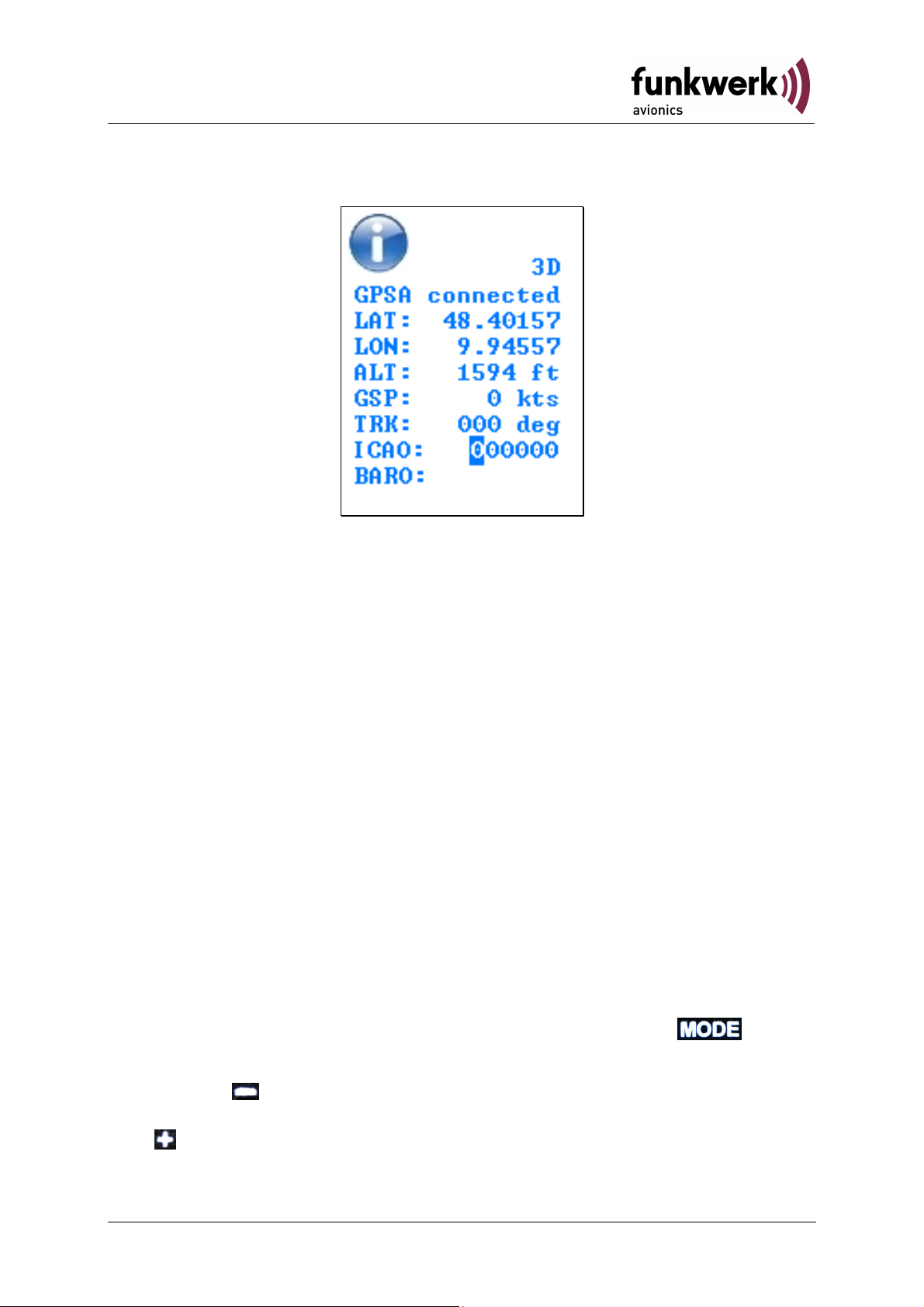
2.6 Information Page
This view provides information about current own aircraft status. The
following information is given:
2D/3D ......... GPS reception
GPSA ......... indicates whether an antenna is connected to the GPS
receiver
LAT ............ own position latitude in decimal degree
LON ........... own position longitude in decimal degree
ALT ............ own altitude in feet (ft)
GSP ........... ground speed
TRK ............ true track
ICAO .......... own ICAO 24-bit address as transmitted by the Mode S
transponder
BARO ......... barometric (uncorrected) altitude as transmitted in ADS-B
reports by the Mode S transponder, used for altitude
comparison with other ADS-B traffic
Furthermore, this page allows to enter the own ICAO 24bit address
manually. When the information page is accessed with the button,
the first digit of the ICAO 24-bit address is highlighted.
By pressing the digits of the ICAO 24-bit address can be selected in
order from left to right. The value at the selected digit can be modified
with .
22Document No.: 03.310.010.71e / Revision: 2.10
Page 24

TM250 / P/N 250TM-(xxx)-(xxx)
Operation and Installation
2.7 Output of traffic data
To connect an additional display device, the TM250 provides traffic data
on pin 8 of the D-Sub socket. Depending on the setting in the
configuration menu (see Section 2.4.7), the data are sent at 9600 baud
in the "pseudo FLARM® protocol" or at 19200 baud in binary format. Use
the orange TRAFFIC out cable and connect it to the input of your display
device. Connect the black GND wire to the ground connection of your
display system.
The specification of the textbased "pseudo FLARM® protocol" of this
interface is available on request.
2.8 Software Update
The TM250 software can be easily updated by the user. Required
components comprise:
• Standard Windows PC
• Update-program (available as download within the Service area of
www.funkwerk-avionics.com)
• USB wire (part of the TM250 delivery)
• TM250
While connecting the TM250 with the PC, the Button must be pressed
and held. The Software can now be updated by running the update
program.
23 Document No.: 03.310.010.71e / Revision: 2.10
Page 25

TM250 / P/N 250TM-(xxx)-(xxx)
Operation and Installation
3 INSTALLATION
3.1 Unpacking and Inspection
Unpack the device carefully. Transport damages must be immediately
reported to the carrier. The original packaging material must be kept for
proof.
For storage or return please use the original packaging.
3.2 Scope of Delivery
Article Number Explanation/ Details
TM250 Traffic Display TM250
M4X8ZSW
(3 pieces)
Mounting screw for panels with a
thickness up to 5 mm
DA-1A03B GPS antenna
TM-USB1 USB cable
PNETAN80 1090MHz/FLARM® antenna in-
cockpit
PNETAA80 1090MHz/FLARM® antenna body
PNETKA80 Power and data cable - TRT
PNETKB80 Power and data cable - Other
03.310.010.71e Manual „Operation and Installation“
24Document No.: 03.310.010.71e / Revision: 2.10
Cockpit ant. + FAV XPDR
Cockpit ant. + Other XPDR Body ant. + FAV XPDR
Body ant. + Other XPDR
Page 26

TM250 / P/N 250TM-(xxx)-(xxx)
Operation and Installation
3.3 Mounting
• In cooperation with aircraft maintenance, a suitable location and
installation method must be determined. All cables can be installed
by the maintenance personnel. Suitable cable kits are available
from Funkwerk Avionics.
• Avoid installing close to heat sources. Sufficient aerial circulation is
necessary.
• When installing the cables and connecting plugs leave enough
space for each.
• Sharp bending and routing of wires close to control cables should
be avoided.
• The cables must be long enough so that plugs are accessible for
repair.
• The cable harness that leads to the device connector must be
placed so that condensation water cannot leak into the plug.
• For installation tips and drawings see chapter 3.5.2 "installation
tips".
• Inside antenna:
o While installing an antenna inside the cockpit, take care that
the pilot’s outside view is not obstructed
o The antenna should be mounted in such a way that the
edges of the antenna are vertically directed
• Outside antenna:
o The FLARM® antenna shall be installed as far as possible
from the transponder antenna to avoid that the own
transponder signals block the reception of other signals.
o In most cases, the transponder antenna is installed on the
bottom of the aircraft; it is thus recommended to install the
FLARM® antenna on top of the fuselage.
25 Document No.: 03.310.010.71e / Revision: 2.10
Page 27

TM250 / P/N 250TM-(xxx)-(xxx)
232
Sub 9 Male)
USB
-
Socket
Operation and Installation
3.4 Connectors
The TM250 includes the following interfaces:
• GPS Antenna
• 1090MHz / FLARM® Antenna
• USB
• Power / RS-232 (NMEA output) / RS-232 (external FLARM®)
1090MHz/
Power + RS-
(D-
Mini
FLARM
Antenna
(SMA)
®
GPS
Antenna
(BNC)
3.4.1 GPS Antenna
A BNC-type socket provides the connection to the active (5V) GPS
antenna that is supplied with the TM250.
3.4.2 1090MHz / FLARM® Antenna
A SMA-type socket provides the connection to a 1090 MHz antenna. Via
this antenna the FLARM® signals (868 MHz) are received, as well.
For the antenna there are different options:
• Standard FLARM® antenna (flexible, for installation inside the
cockpit, PNETAN80, see 3.2 Scope of Delivery)
• GSM rod antenna (for installation on the aircraft’s body,
PNETAA80, see 3.2 Scope of Delivery)
26Document No.: 03.310.010.71e / Revision: 2.10
Page 28

TM250 / P/N 250TM-(xxx)-(xxx)
B signals
please make sure that the transponder used is capable to
A signals at the respective
interface. To achieve this, it might be necessary to change
ol NMEA / 4800
Operation and Installation
Antennas installed inside the cockpit should still allow a good outside
view.
Both antenna types shall be installed vertically and with a large distance
to the transponder antenna.
3.4.3 USB
Via the USB socket and the USB cable supplied together with the
TM250, ADS-B DF17/18 reports that are received by the TM250 can be
provided to an external PC in binary format. The USB socket also allows
updating the software (see 2.8).
3.4.4 Power / RS-232
Through this 9-pole D-Sub socket (male) the TM250 is supplied with
power.
In addition, this socket provides the RS-232 signals to connect a
TRT800 (A/H) transponder.. With this connection the transponder
obtains the NMEA signals from the internal GPS receiver of the TM250
for the transmission of ADS-B reports.
In order to assure the proper transmission of ADSprocess respective NME
the settings of the transponder (protoc
Baud).
Another RS-232 interface allows connecting an external FLARM®
receiver as well as a display system. (When the USB socket is used,
however, this interface is deactivated).
A suitable connection cable is supplied together with the TM250.
27 Document No.: 03.310.010.71e / Revision: 2.10
Page 29

TM250 / P/N 250TM-(xxx)-(xxx)
Operation and Installation
Connector Pin-Out
PIN # I/O Term Function
1 O Audio Digital Digital Audio out
2 I GPS Rx GPS Receiver Input (for
3 O GPS Tx GPS Receiver Output (NMEA for
4 O Audio Analogue Analogue Audio out
5 I/O GND Signal Ground
6 - Supply PWR Power Input (9-33 V DC)
configuration)
TRT800)
7 I FLARM-Rx Input from external FLARM
8 O TRAFFIC-Tx Traffic data output
9 - DC-GND Power Supply Ground
Rear View:
1 5
6 9
The power supply has the following requirements:
• Voltage: 9 .. 33 V DC
• Current: approx. 0.16A at 13.8 V (2.2 W)
The ON/OFF switch completely disconnects the TM250 from aircraft
power, so that the internal electronics can be protected against
overvoltage, e.g. during engine start.
28Document No.: 03.310.010.71e / Revision: 2.10
Page 30

TM250 / P/N 250TM-(xxx)-(xxx)
Operation and Installation
3.5 Device Dimensions
3.5.1 Housing
The TM250 is a device which is to be installed in a cockpit panel with a
standard 2-1/4 inch (57 mm) diameter cut-out.
The device has the following dimensions:
Width: 65 mm
Height: 65 mm
Depth: 102 mm (without front plate and connectors)
The built-in display has the following dimensions:
Width: 31.2 mm (visible area)
Height: 41.7 mm (visible area)
Resolution: 132 x 176 pixels
Colors: 65,536
29 Document No.: 03.310.010.71e / Revision: 2.10
Page 31

TM250 / P/N 250TM-(xxx)-(xxx)
≈
57,5 mm
Ø
Fixing clips (spring)
Operation and Installation
3.5.2 Installation Tips
80 mm
Connection area
left / right
Panel cut out
47,0 mm
4 x Ø 4 mm
47,0 mm
Connector (plug) has to be clamped with both spring locks
3.6 Post-installation Checks
All control functions of the aircraft must be checked to eliminate risk of
interference due to wiring.
3.7 Accessories
Additional accessories, like antennas, cable harnesses and plugs can be
found on the current price-list. Or visit the online shop on www.funkwerkavionics.com.
30Document No.: 03.310.010.71e / Revision: 2.10
Page 32

TM250 / P/N 250TM-(xxx)-(xxx)
Operation and Installation
4 APPENDICES
4.1 Technical Data
Applied regulations RTCA DO 260A Change 2
Temperature areas
Operating 0 °C to +55 °C; for 30 min +70°C
Storage -30 °C to +85 °C
Power Supply 13,8 VDC (9 VDC .. 33 VDC)
approx. 0.16 Amp. at 13.8 VDC
2,2 W (max)
Protection external 2 Amp. protection required
Mounting Installation cut-out diameter 57,5 mm
Weight 280 g
31 Document No.: 03.310.010.71e / Revision: 2.10
Page 33

TM250 / P/N 250TM-(xxx)-(xxx)
Operation and Installation
4.2 Wiring Diagram
4.2.1 Cable Harness for TRT-Serie (XPDR)
32Document No.: 03.310.010.71e / Revision: 2.10
Page 34

TM250 / P/N 250TM-(xxx)-(xxx)
Operation and Installation
4.2.2 Cable Harness for OEM-device (XPDR)
33 Document No.: 03.310.010.71e / Revision: 2.10
Page 35
TM250 / P/N 250TM-(xxx)-(xxx)
Operation and Installation
4.3 Threat Classifications – Zone Division
Basically, the collision warning is based on the comparison of the own
position with the location of surrounding traffic. With ADS-B traffic, this is
done using the respective position reports. For Mode S traffic (not ADS-B
capable), the field strength is measured. The proximity of FLARM® traffic
is detected whenever a signal is received (which suffices as the
maximum range of FLARM® reception is relatively small).
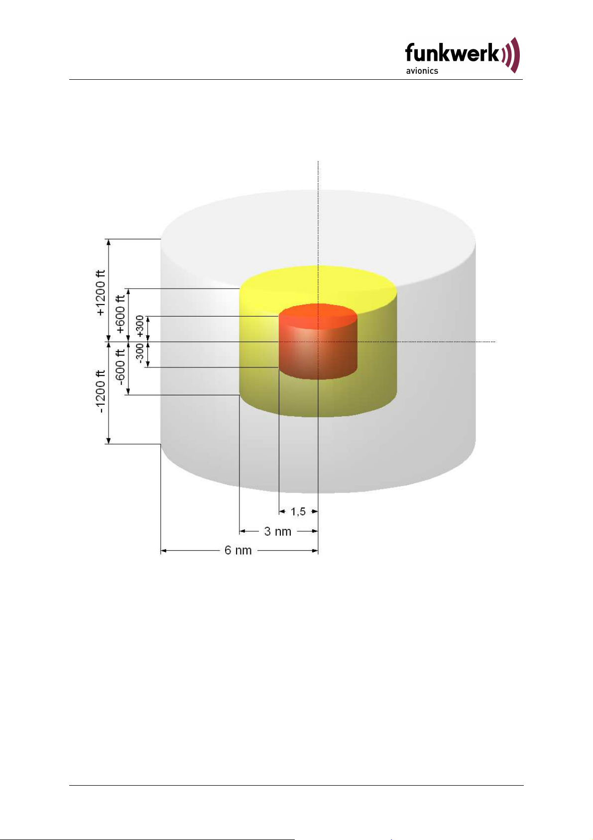
The priority of a collision warning is determined on the basis of three
predefined zones. These are defined in each case by a distance radius
as well as by an altitude range around own position.
34Document No.: 03.310.010.71e / Revision: 2.10
Page 36

TM250 / P/N 250TM-(xxx)-(xxx)
Operation and Installation
Zone 1: If a traffic item closes in to less than 6 NM with an altitude
difference (relative altitude) of less than 1200 ft, the first zone
is injured. In the traffic display the traffic symbol changes to a
filled diamond . This proximity alert does not yet indicate a
threat.
Zone 2: If a traffic item closes in to less than 3 NM with an altitude
difference (relative altitude) of less than 600 ft, the second
zone is injured. In the traffic display the traffic symbol
changes into a yellow full circle . This classifies the target
as a potential threat.
Zone 3: If a traffic item is less than 1.5 NM away with an altitude
difference (relative altitude) of less than 300 ft, the third and
most critical zone is injured. In the traffic display the traffic
symbol changes into a red full square . The target is thus
classified as an imminent threat that requires immediate
action.
Besides the spatial boundaries of these zones, the approach rate is also
taken into account.
An alarm equal to the zone 2 violation will be raised if an encounter is
forecasted in less than 70 seconds. This will happen regardless of the
zone in which the intruder is. (obsolete if target is already inside zone 3).
An alarm equal to the zone 3 violation will be raised if an encounter is
forecasted in less than 20 seconds. This happens regardless of the zone
in which the intruder is..
For Mode S traffic the measured field strength will be compared to predefined threshold values, as well as the flight level (when transmitted).
Mode S traffic is using only two zones wherein the zones 1 and 2 are
combined into one.
Regarding FLARM®, the range of reception is comparable to the zone 2
boundaries.
35 Document No.: 03.310.010.71e / Revision: 2.10
Page 37

TM250 / P/N 250TM-(xxx)-(xxx)
Operation and Installation
Notes:
36Document No.: 03.310.010.71e / Revision: 2.10
Page 38
Funkwerk Avionics GmbH
Heinz
-
Strachowitz
-
Str. 4
Traffic Monitor
TM250
2004/108/EG
EMV Richtlinie
EN 55022:2006 + A1:2007
n/a
Buchloe, 01.04.2013
2.0
Hersteller / Manufacturer / Fabricant
Anschrift / Address / Adresse
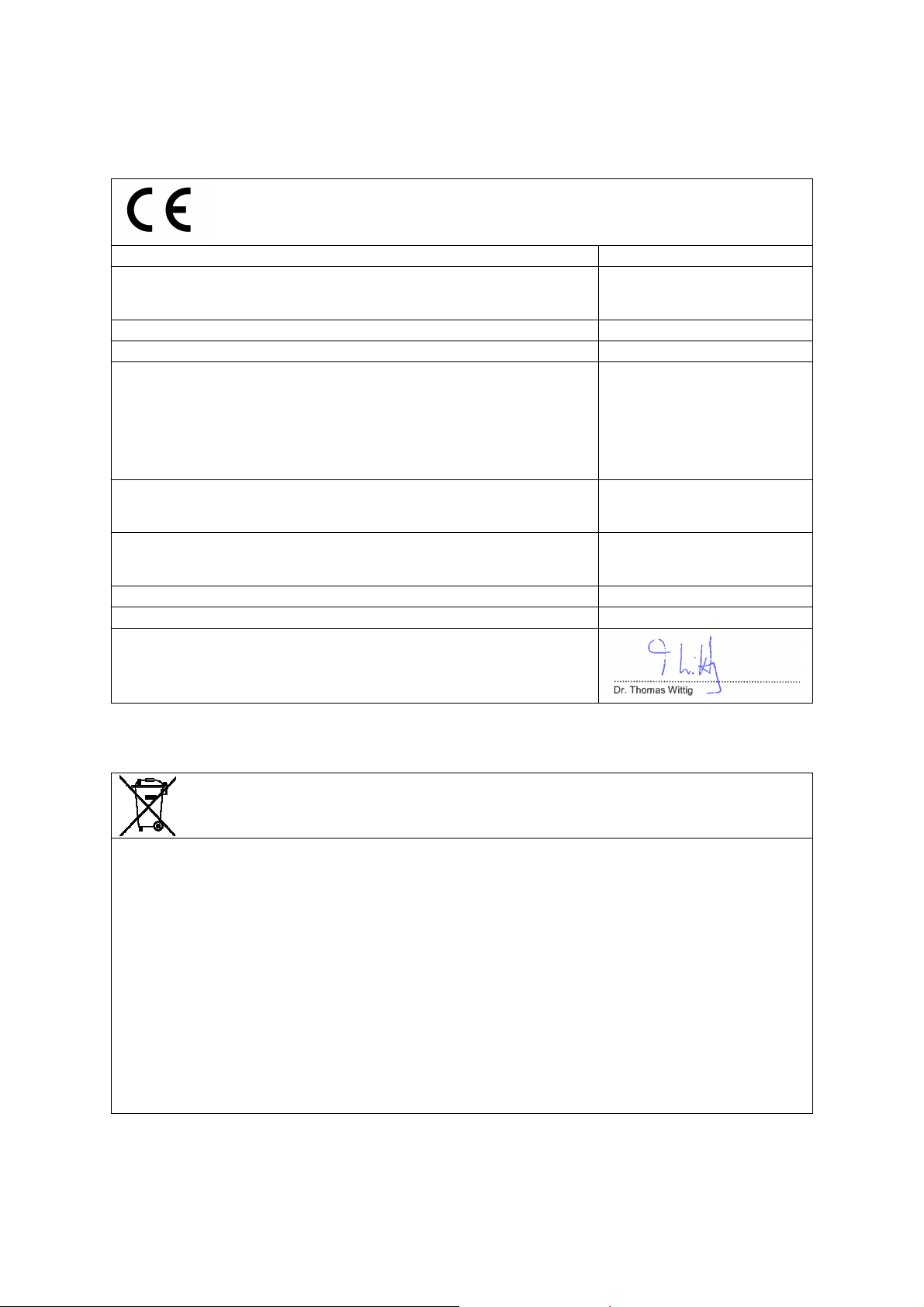
EG-Konformitätserklärung
EC-Declaration of Conformity
CE-Déclaration de conformité
Produktbezeichnung / Product specification / Description du produit
Typen / Types / Types
Wir erklären in alleiniger Verantwortung, daß das (die) oben bezeichnete
Produkt(e) mit folgenden Europäischen Richtlinien übereinstimmt
(übereinstimmen) /
We declare under our sole responsibility that above product(s) is (are) in
conformity with the following directives /
Déclarons sous notre seule responsibilité, que le(s) produit(s) repond(ent)
aux directives suivantes
Angewandte harmonisierte Normen und technischen Spezifikationen /
Applied harmonised standards and technical specifications /
Normes harmonisées et spécifications techniques:
Benannte Stelle und Nummer der EG-Baumusterprüfbescheinigung /
Notified Body and number of the EC-type-examination certificate /
Organisme agreé et número dú certificate des test CE
Ort, Datum der Ausstellung / Place, date of issue / Lieu, date de lédition
Revision
Name und Unterschrift des Befugten /
Name and signature of authorized person /
Nom et signature de la personne autorisée:
Umweltinformationen für Kunden innerhalb der Europäischen Union
Regulatory and Compliance/WEEE Legislation within the European Union
DE-86807 Buchloe
Germany
2004/108/EC EMC Directive
2004/108/CE Directive CEM
EN 55024:1998 + A1:2001 +
A2:2003
Gemäß der Europäischen Richtlinie 2002/96/EG über Elektro- und Elektronik-Altgeräte (WEEE) und die
Änderung 2008/34/EG dürfen Produkte, die direkt am Gerät und/oder an der Verpackung mit diesem Symbol
versehen sind, nicht zusammen mit gewöhnlichem Abfall entsorgt werden, sondern sind über die für
elektrische und elektronische Geräte zuständigen und von der Regierung oder örtlichen Behörden dazu
bestimmten Sammelstellen zu entsorgen. Ordnungsgemäßes Entsorgen und Recyceln trägt dazu bei,
potentielle negative Folgen für Umwelt und die menschliche Gesundheit zu vermeiden. Wenn Sie weitere
Informationen zur Entsorgung Ihrer Altgeräte benötigen, wenden Sie sich bitte an die örtlichen Behörden oder
städtischen Entsorgungsdienste oder an den Händler, bei dem Sie das Produkt erworben haben.
According to the European directive 2002/96/EC on waste electrical and electronic equipment (WEEE) an the
amendment 2008/34/EC: Products, that are marked with the above symbol directly at the device and/or at the
packaging, may not to be disposed together with ordinary waste, but have to be disposed using the
appropriate differentiated collection centres for electronic and electro waste. Appropriate differentiated waste
collection and recycling helps to prevent possible negative environmental and health effects. If you need
additional information about the disposal of your products after the end of their working life, please contact
your local authorities or municipal waste disposal organisation, or the dealer you have purchased the product
from.
Page 39

Page 40

Funkwerk Avionics GmbH
Heinz-Strachowitz-Str. 4
DE-86807 Buchloe
Germany
phone.: +49-8241 80066 0
fax.: +49-8241 80066 99
E-mail:
service@funkwerk-avionics.com
www.funkwerk-avionics.com
 Loading...