

Page 1

User’s Guide
bintec R4100 / R4300
Technical Data
Copyright © July 17, 2006 Funkwerk Enterprise Communications GmbH
Version 0.9
Page 2

Purpose This document is part of the user’s guide to the installation and configuration of bintec gateways run-
ning software release 7.4.5 or later. For up-to-the-minute information and instructions concerning the
latest software release, you should always read our Release Notes, especially when carrying out a
software update to a later release level. The latest Release Notes can be found at
ec.com.
Liability While every effort has been made to ensure the accuracy of all information in this manual, Funkwerk
Enterprise Communications GmbH cannot assume liability to any party for any loss or damage caused
by errors or omissions or by statements of any kind in this document and is only liable within the scope
of its terms of sale and delivery.
The information in this manual is subject to change without notice. Additional information, changes and
Release Notes for bintec gateways can be found at
As multiprotocol gateways, bintec gateways set up WAN connections in accordance with the system
configuration. To prevent unintentional charges accumulating, the operation of the product should be
carefully monitored. Funkwerk Enterprise Communications GmbH accepts no liability for loss of data,
unintentional connection costs and damages resulting from unsupervised operation of the product.
Trademarks bintec and the bintec logo are registered trademarks of Funkwerk Enterprise Communications GmbH.
Other product names and trademarks mentioned are usually the property of the respective companies
and manufacturers.
Copyright All rights are reserved. No part of this publication may be reproduced or transmitted in any form or by
any means – graphic, electronic, or mechanical – including photocopying, recording in any medium,
taping, or storage in information retrieval systems, without the prior written permission of Funkwerk En
terprise Communications GmbH. Adaptation and especially translation of the document is inadmissible
without the prior consent of Funkwerk Enterprise Communications GmbH.
Guidelines and standards bintec gateways comply with the following guidelines and standards:
R&TTE Directive 1999/5/EG
CE marking for all EU countries and Switzerland
You will find detailed information in the Declarations of Conformity at www.funkwerk-ec.com.
How to reach Funkwerk
Enterprise Communications
GmbH
Funkwerk Enterprise Communications GmbH
Suedwestpark 94
D-90449 Nuremberg
Germany
Telephone: +49 180 300 9191 0
Fax: +49 180 300 9193 0
Internet: www.funkwerk-ec.com
www.funkwerk-ec.com.
Bintec France
6/8 Avenue de la Grande Lande
F-33174 Gradignan
France
Telephone: +33 5 57 35 63 00
Fax: +33 5 56 89 14 05
Internet: www.bintec.fr
www.funkwerk-
-
Page 3

1 bintec R4100 . . . . . . . . . . . . . . . . . . . . . . . . . . . . . . . . . . . . . . . . . . . 3
1.1 Delivery size . . . . . . . . . . . . . . . . . . . . . . . . . . . . . . . . . . . . . . . . . . . . . . . . 3
1.2 General Product Features . . . . . . . . . . . . . . . . . . . . . . . . . . . . . . . . . . . . . 3
1.3 LEDs . . . . . . . . . . . . . . . . . . . . . . . . . . . . . . . . . . . . . . . . . . . . . . . . . . . . . . 5
1.4 Connections . . . . . . . . . . . . . . . . . . . . . . . . . . . . . . . . . . . . . . . . . . . . . . . . 7
1.5 Pin Assignments . . . . . . . . . . . . . . . . . . . . . . . . . . . . . . . . . . . . . . . . . . . . . 8
1.5.1 Ethernet Interfaces . . . . . . . . . . . . . . . . . . . . . . . . . . . . . . . . . . . . 8
1.5.2 ISDN Basic Rate Interfaces . . . . . . . . . . . . . . . . . . . . . . . . . . . . . 10
1.5.3 ISDN-PRI Interfaces . . . . . . . . . . . . . . . . . . . . . . . . . . . . . . . . . . 11
2 bintec R4300 . . . . . . . . . . . . . . . . . . . . . . . . . . . . . . . . . . . . . . . . . . 13
2.1 Delivery size . . . . . . . . . . . . . . . . . . . . . . . . . . . . . . . . . . . . . . . . . . . . . . . 13
2.2 General Product Features . . . . . . . . . . . . . . . . . . . . . . . . . . . . . . . . . . . . 13
2.3 LEDs . . . . . . . . . . . . . . . . . . . . . . . . . . . . . . . . . . . . . . . . . . . . . . . . . . . . . 15
2.4 Connections . . . . . . . . . . . . . . . . . . . . . . . . . . . . . . . . . . . . . . . . . . . . . . . 17
2.5 Pin Assignments . . . . . . . . . . . . . . . . . . . . . . . . . . . . . . . . . . . . . . . . . . . . 18
2.5.1 Ethernet Interfaces . . . . . . . . . . . . . . . . . . . . . . . . . . . . . . . . . . . 18
2.5.2 ISDN Basic Rate Interfaces . . . . . . . . . . . . . . . . . . . . . . . . . . . . . 20
2.5.3 X.21 Interfaces . . . . . . . . . . . . . . . . . . . . . . . . . . . . . . . . . . . . . . 21
Technical Data bintec User’s Guide
1
Page 4

2
bintec User’s Guide Technical Data
Page 5

1 bintec R4100
1.1 Delivery size
Your gateway is supplied with the following parts:
■ Cable sets/power supply:
– Ethernet cable
– ISDN cable
– Serial cable
– Splitter serial/Ethernet
– Power supply
bintec R4100
1
■ Funkwerk Companion CD
■ Documentation:
– Quick Install Guide (printed)
– User’s Guide (on CD)
– Release Notes, if required
– Safety Instructions
1.2 General Product Features
The general product features cover performance features and the technical requirements for installation and operation of your gateway.
These features are outlined in the following table:
Feature Data
Product name bintec R4100
Technical Data bintec User’s Guide
3
Page 6

1
bintec R4100
Feature Data
Dimensions/weight (B x H x D):
Dimensions without cables
Weight
Transport weight (incl. documentation, cabling, packaging)
Memory 32 MB SDRAM,
LEDs 20 (1x Power, 1x Status, 5x2 Ethernet,
Power consumption of equipment max. 15 Watt, typ. 10 Watt
Voltage supply 24V DC 1A EU PSU
Ambient requirements:
Storage temperature
Ambient temperature
Relative humidity
Room classification
295 mm x 160 mm x 41 mm
approx. 1260 g
approx. 2,6 kg
8 MB Flash-ROM
4x2 Function)
-20° to +70°C
0 to 40 °C
10 to 90% non-condensing in operation
5 to 95% non-condensing in storage
Operate only in dry rooms.
4
Available interfaces:
Ethernet IEEE 802.3 LAN
(4 port switch)
one port with serial interface mode
ISDN-WAN S0 (2)
ISDN-PRI (2)
DMZ/ETH5
bintec User’s Guide Technical Data
Built-in (twisted-pair only),
10/100 Mbps, auto sensing, MDIX;
supports the following baud rates:
1200, 2400, 4800, 9600, 19200,
38400, 57600, 115200 bauds
Built-in
Built-in
Additional Ethernet switch port
Page 7

Feature Data
Plugs used:
bintec R4100
1
Serial interface
Ethernet interface
ISDN interface
ISDN-PRI interface
SAFERNETTM Security Technology
Software includes BRICKware for Windows
Printed documentation included Quick Install Guide
Documentation in PDF format User’s Guide
Table 1-1: General product features
RJ45
RJ45
RJ45
RJ45
Community Passwords, PAP, CHAP,
MS-CHAP, MS-CHAP v.2, PPTP,
PPPoE, PPPoA, Callback, Access
Control Lists, CLID, NAT, SIF, VPN
mit PPTP or IPSec, MPPE Encryption,
PPTP Encryption
BRICKtools for Unix
BRICKware for Windows
Software Reference
Technical Data bintec User’s Guide
1.3 LEDs
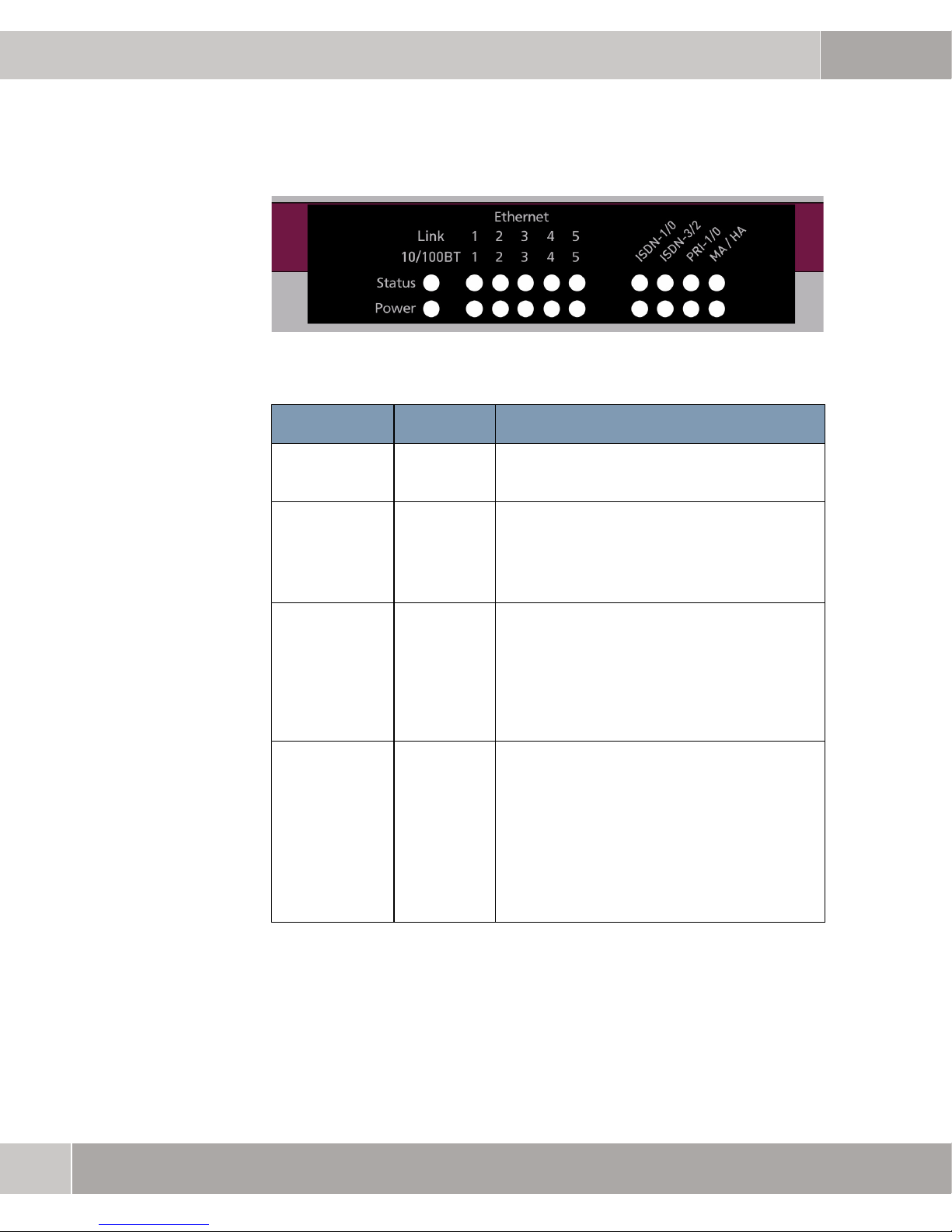
The LEDs on your bintec R4100 Gateway indicate the states and the activity of the gateway.
They are arranged as follows:
5
Page 8
1
bintec R4100
Figure 1-1: LEDs on bintec R4100
In operational mode the LEDs display the following status information:
LED Status Information
Power off
on
Status perma-
nently on or
off
flashing
Ethernet 1 to 5
upper line:
lower line:
ISDN-1/0
upper line:
lower line:
on
flashing
on
off
on
flashing
on
flashing
Power is off.
Power is on.
Error.
The gateway is active.
The gateway is connected to the Ethernet.
Data traffic via the Ethernet interface.
Data traffic with 100 mbps
Data traffic with 10 mbps
ISDN-0: ISDN D channel is active.
ISDN-0: At least one ISDN B channel is
active.
ISDN-1: ISDN D channel is active.
ISDN-1: At least one ISDN B channel is
active.
6
bintec User’s Guide Technical Data
Page 9

LED Status Information
ISDN-3/2
bintec R4100
1
upper line:
lower line:
PRI 1/0
MA / HA
upper line:
lower line:
on
flashing
on
flashing
on
flashing
on
flashing
flashing
on
ISDN-2: ISDN D channel is active.
ISDN-2: At least one ISDN B channel is
active.
ISDN-3: ISDN D channel is active.
ISDN-3: At least one ISDN B channel is
active.
PRI-0: ISDN D channel is active.
PRI-0: At least one ISDN B channel is
active.
PRI-1: ISDN D channel is active.
PRI-1: At least one ISDN B channel is
active.
BRRP packets are received.
A user is logged in to the system, e.g. via
telnet.
Table 1-2: LED status display
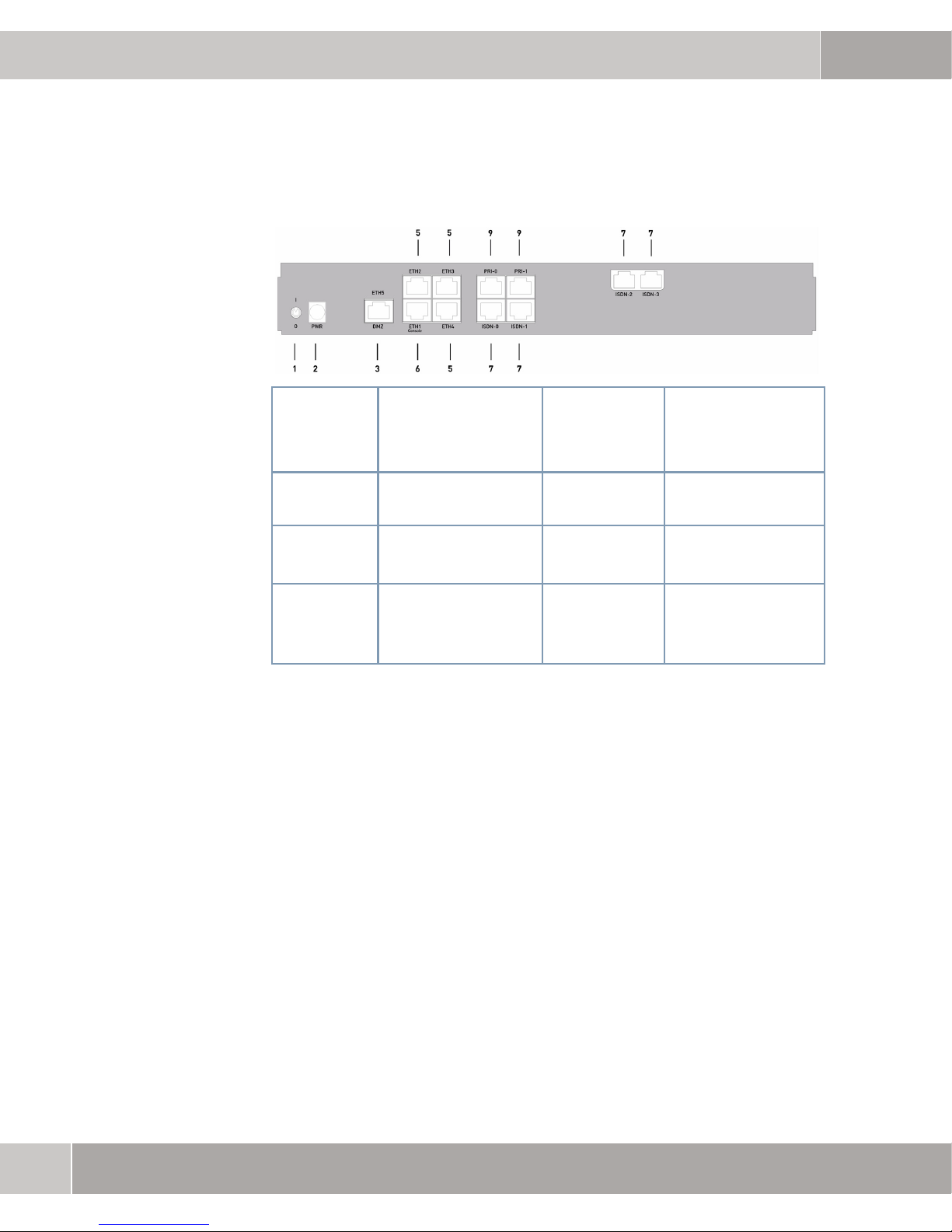
1.4 Connections
All connections are located on the rear of the gateway. bintec R4100 offers
a 4-port Ethernet switch including a port with serial interface mode, a
DMZ/ETH5 interface, four ISDN interfaces as well as two ISDN-PRI interfaces.
Technical Data bintec User’s Guide
7
Page 10
1
bintec R4100
The connections are arranged as follows:
1. I/O Power Switch 6.
2.
PWR
3.
DMZ/ETH5
5.
ETH2ETH4
Figure 1-2: bintec R4100 rear
Socket for power
supply
Ethernet interface 8. PRI-0 -
Ethernet interface
1.5 Pin Assignments
1.5.1 Ethernet Interfaces
ETH1/
Console
7. ISDN-0 ISDN-3
PRI-1
Ethernet interface
with serial interface
mode
ISDN interface
ISDN-PRI interface
bintec R4100 offers an Ethernet interface with integrated 4-port switch
(ETH1 - ETH4) and a separate Ethernet interface (DMZ/ETH5).
The 4-port switch can be used to connect single PCs as well as additional
switches
The ETH1/Console interface can also be used as serial interface.
The DMZ/ETH5 interface can be used to connect an optional DSL modem or a
DMZ.
8
bintec User’s Guide Technical Data
Page 11

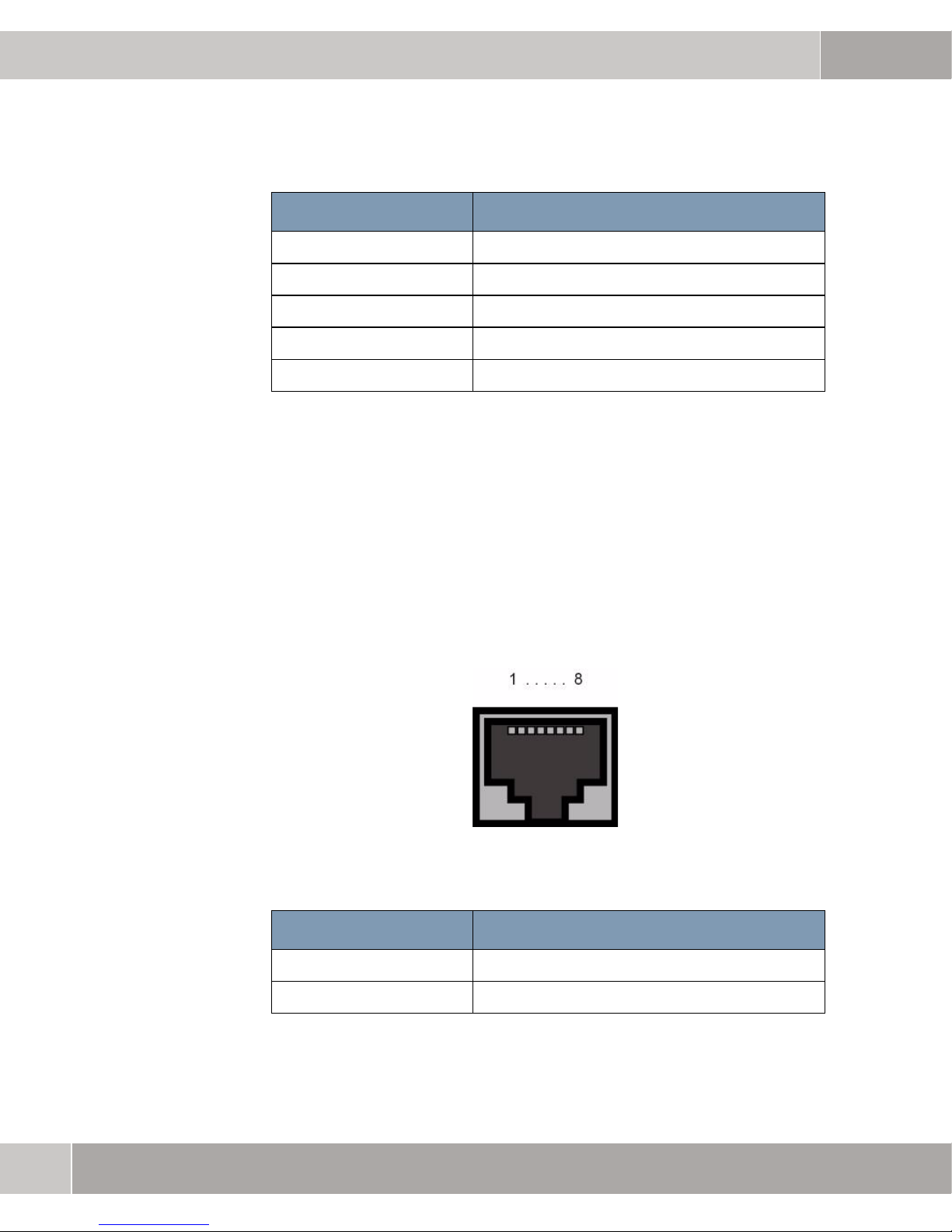
An RJ45 socket is used for connecting:
Figure 1-3: Ethernet 10/100Base-T interface (RJ45 socket)
The Ethernet sockets have the following pin assignment:
Pin Function
bintec R4100
1
1 TD +
2 TD -
3 RD +
4 Not used
5 Not used
6 RD -
7 Not used
8 Not used
Table 1-3: RJ45 socket for Ethernet connection
The Ethernet sockets are not equipped with Auto-MDIX technology.
The combined Serial-Ethernet-sockets have the following pin assignment:
Pin Function
1 TD + (Ethernet)
2 TD - (Ethernet)
Technical Data bintec User’s Guide
3 RD + (Ethernet)
9
Page 12
1
bintec R4100
Pin Function
4 RX (Console)
5 GND (Console)
6 RD - (Ethernet)
7 GND (Console)
8 TX (Console)
Table 1-4: RJ45 socket for Ethernet connection resp. serial interface (Console)
The combined Serial-Ethernet-sockets are not equipped with Auto-MDIX technology.
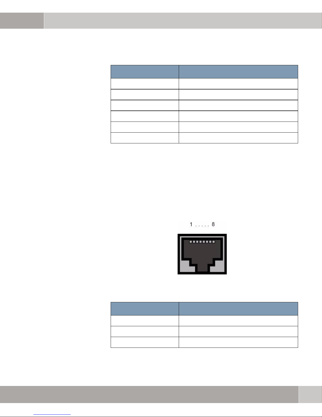
1.5.2 ISDN Basic Rate Interfaces
bintec R4100 provides four ISDN S0 interface, which can be used, e.g., for
backup purposes.
A RJ45 socket is used for connecting:
Figure 1-4: ISDN S0 interface (RJ45 socket)
The ISDN interface (RJ45 socket) has the following pin assignment:
Pin Function
1 Not used
2 Not used
10
bintec User’s Guide Technical Data
Page 13
Pin Function
3 Send (+)
4 Receive (+)
5 Receive (-)
6 Send (-)
7 Not used
8 Not used
Table 1-5: RJ45 socket for ISDN connection
1.5.3 ISDN-PRI Interfaces
bintec R4100
1
The ISDN-PRI interfaces are connected using a RJ45 socket. The supplied
cable combines the RJ45 plug required for the ISDN-PRI connection and
the RJ45 plug required by the gateway.
Only the inner pins are used for the ISDN-PRI connection:
Figure 1-5: ISDN-PRI interface (RJ45 socket)
The ISDN-PRI interface (RJ45 socket) has the following pin assignment:
Pin Function
1 T +
2 T -
Technical Data bintec User’s Guide
3 Not used
11
Page 14

1
bintec R4100
Pin Function
4 R +
5 R -
6 Not used
7 Not used
8 Not used
Table 1-6: RJ45 socket for ISDN-PRI connection
Note for NTs in Germany
In Germany, "Transmit" (NT-->TE) is often designated "S2Mab" (a and b) on the
plug and "Receive" (TE-->NT) "S2Man" (a and b).
12
bintec User’s Guide Technical Data
Page 15

2 bintec R4300
2.1 Delivery size
Your gateway is supplied with the following parts:
■ Cable sets/power supply:
– Ethernet cable
– ISDN cable
– Serial cable
– Power supply
– X.21 DTE (optional)
– X.21 DCE (optional)
– V.35 DTE (optional)
bintec R4300
2
■ Funkwerk Companion CD
■ Documentation:
– Quick Install Guide (printed)
– User’s Guide (on CD)
– Release Notes, if required
– Safety Instructions
2.2 General Product Features
The general product features cover performance features and the technical requirements for installation and operation of your gateway.
These features are outlined in the following table:
Feature Data
Product name bintec R4300
Technical Data bintec User’s Guide
13
Page 16

2
bintec R4300
Feature Data
Dimensions/weight (B x H x D):
Dimensions without cables
Weight
Transport weight (incl. documentation, cabling, packaging)
Memory 32 MB SDRAM,
LEDs 20 (1x Power, 1x Status, 5x2 Ethernet,
Power consumption of equipment max. 15 Watt, typ. 13 Watt
Voltage supply 15V AC 1.3A EU PSU
Ambient requirements:
Storage temperature
Ambient temperature
Relative humidity
Room classification
295 mm x 160 mm x 41 mm
approx. 1260 g
approx. 2.6 kg
8 MB Flash-ROM
4x2 Function)
-20° to +70°C
0 to 40 °C
10 to 90% non-condensing in operation
5 to 95% non-condensing in storage
Operate only in dry rooms.
14
Available interfaces:
Ethernet IEEE 802.3 LAN
(4 port switch)
one port with serial interface mode
ISDN-WAN S0 (2)
DMZ/ETH5
X.21 interface (2)
bintec User’s Guide Technical Data
Built-in (twisted-pair only),
10/100 Mbps, auto sensing, MDIX;
supports the following baud rates:
1200, 2400, 4800, 9600, 19200,
38400, 57600, 115200 bauds
Built-in
Additional Ethernet switch port
Built-in
Page 17

Feature Data
Plugs used:
bintec R4300
2
Serial interface
Ethernet interface
ISDN interface
X.21 interface
SAFERNETTM Security Technology
Software includes BRICKware for Windows
Printed documentation included Quick Install Guide
Documentation in PDF format User’s Guide
Table 2-1: General product features
RJ45
RJ45
RJ45
26-pole mini Delta ribbon socket
Community Passwords, PAP, CHAP,
MS-CHAP, MS-CHAP v.2, PPTP,
PPPoE, PPPoA, Callback, Access
Control Lists, CLID, NAT, SIF, MPPE
Encryption, PPTP Encryption, VPN
with PPTP or IPSec
BRICKtools for Unix
BRICKware for Windows
Software Reference
2.3 LEDs
The LEDs on your bintec R4300 Gateway indicate the states and the activity of the gateway.
They are arranged as follows:
Technical Data bintec User’s Guide
15
Page 18

2
bintec R4300
Figure 2-1: LEDs on bintec R4300
In operational mode the LEDs display the following status information:
LED Status Information
Power off
on
Status perma-
nently on or
off
flashing
Ethernet 1 to 5
upper line:
lower line:
ISDN-0 B/D
upper line:
lower line:
ISDN-1 B/D
upper line:
on
flashing
on
off
on
on
flashing
on
Power is off.
Power is on.
Error.
The gateway is active.
The gateway is connected to the Ethernet.
Data traffic via the Ethernet interface.
Data traffic with 100 mbps
Data traffic with 10 mbps
ISDN D channel is active.
One ISDN B channel is active.
Both ISDN B channels are active.
ISDN D channel is active.
lower line:
16
bintec User’s Guide Technical Data
on
flashing
One ISDN B channel is active.
Both ISDN B channels are active.
Page 19

LED Status Information
X.21 2/1
bintec R4300
2
upper line:
lower line:
MA / HA
upper line:
lower line:
Table 2-2: LED status display
on
flashing
on
flashing
flashing
on
X.21 1: Link is established.
X.21 1: Data traffic
X.21 2: Link is established.
X.21 2: Data traffic
BRRP packets are received.
A user is logged in to the system, e.g. via
telnet.
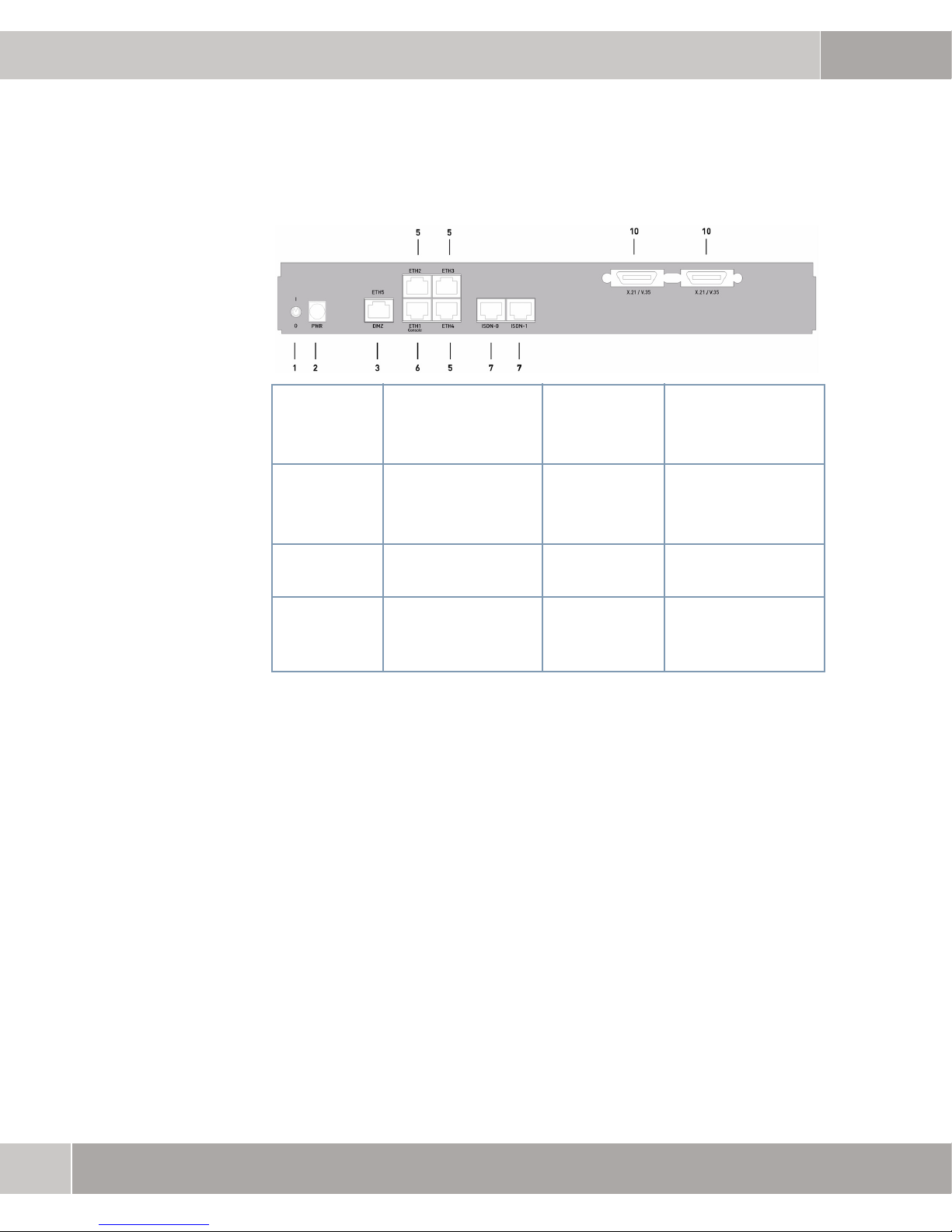
2.4 Connections
All connections are located on the rear of the gateway. bintec R4300 offers
a 4-port Ethernet switch including a port with serial interface mode, a
DMZ/ETH5 interface, two ISDN interfaces as well as two X.21 interfaces.
Technical Data bintec User’s Guide
17
Page 20
2
bintec R4300
The connections are arranged as follows:
1. I/O Power Switch 6.
2.
PWR
3.
DMZ/ETH5
5.
ETH2 ETH4
Figure 2-2: bintec R4300 rear
Socket for power
supply
Ethernet interface 10. X.21 X.21 interface
Ethernet interface
2.5 Pin Assignments
2.5.1 Ethernet Interfaces
ETH1/
Console
7.
ISDN-0 ISDN-1
Ethernet interface
with serial interface
mode
ISDN interface
bintec R4300 offers an Ethernet interface with integrated 4-port switch
(ETH1 - ETH4) and a separate Ethernet interface (DMZ/ETH5).
The 4-port switch can be used to connect single PCs as well as additional
switches
The ETH1/Console interface can also be used as serial interface.
18
bintec User’s Guide Technical Data
Page 21

bintec R4300
The DMZ/ETH5 interface can be used to connect an optional DSL modem or a
DMZ.
An RJ45 socket is used for connecting:
Figure 2-3: Ethernet 10/100Base-T interface (RJ45 socket)
The Ethernet sockets have the following pin assignment:
2
Pin Function
1 TD +
2 TD -
3 RD +
4 Not used
5 Not used
6 RD -
7 Not used
8 Not used
Table 2-3: RJ45 socket for Ethernet connection
The Ethernet sockets are not equipped with Auto-MDIX technology.
The combined Serial-Ethernet-sockets have the following pin assignment:
Pin Function
Technical Data bintec User’s Guide
1 TD + (Ethernet)
19
Page 22

2
bintec R4300
Pin Function
2 TD - (Ethernet)
3 RD + (Ethernet)
4 RX (Console)
5 GND (Console)
6 RD - (Ethernet)
7 GND (Console)
8 TX (Console)
Table 2-4: RJ45 socket for Ethernet connection resp. serial interface (Console)
The combined Serial-Ethernet-sockets are not equipped with Auto-MDIX technology.
2.5.2 ISDN Basic Rate Interfaces
bintec R4300 provides two ISDN S0 interfaces, which can be used, e.g., for
backup purposes.
A RJ45 socket is used for connecting:
Figure 2-4: ISDN S0 interface (RJ45 socket)
20
bintec User’s Guide Technical Data
Page 23

bintec R4300
The ISDN interface (RJ45 socket) has the following pin assignment:
Pin Function
1 Not used
2 Not used
3 Send (+)
4 Receive (+)
5 Receive (-)
6 Send (-)
7 Not used
8 Not used
2
Table 2-5: RJ45 socket for ISDN connection
2.5.3 X.21 Interfaces
bintec R4300 provides two X.2 interfaces.
A 26-pole mini Delta ribbon socket is used for connecting:
Figure 2-5: X.21 interface (26-pole mini Delta ribbon socket)
Technical Data bintec User’s Guide
21
Page 24

2
bintec R4300
The X.21 interface (26-pole mini Delta ribbon socket) has the following pin assignment:
X.21
Signal Pin no.
Shield A1 (1) 1 1 A A 1 1
GND A2 (2) 8 8 B B 19 19
TxD (B) A3 (3) 9 11 S T 22 24
TxD (A) A4 (4) 2 4 P R 4 6
RxD (B) A5 (5) 11 9 T S 24 22
RxD (A) A6 (6) 4 2 R P 6 4
RTS (B) A7 (7) 10 12 25 27
RTS (A) A8 (8) 3 5 C D 7 9
CTS (B) A9 (9) 12 10 27 25
CTS (A) A10 (10) 5 3 D C 9 7
RxC (B) A11 (11) 13 14 X W 26 35
RxC (A) A12 (12) 6 7 V U 8 17
(DB-15)
DTE DCE DTE DCE DTE DCE
V.35
(M34)
V.36
(DB-37)
22
Mode DCE A13 (13) 8 B 19
Mode 0 B1 (14) 19 19
DTR (B) B2 (15) 30 29
DTR (A) B3 (16) H E 12 11
DCD (B) B4 (17) 31 31
DCD (A) B5 (18) F F 13 13
DSR (B) B6 (19) 29 30
DSR (A) B7 (20) E H 11 12
TxC (B) B8 (21) AA AA 23 23
TxC (A) B9 (22) Y Y 5 5
bintec User’s Guide Technical Data
Page 25

bintec R4300
2
X.21
Signal Pin no.
Mode 1 B10 (23)
Mode 2 B11 (24) 8 8
TxCE (B) B12 (25) 13 W X 35 26
TxCE (A) B13 (26) 6 U V 17 8
Table 2-6: DB-15 socket for X.21 connection
(DB-15)
DTE DCE DTE DCE DTE DCE
V.35
(M34)
V.36
(DB-37)
Technical Data bintec User’s Guide
23
Page 26

2
bintec R4300
24
bintec User’s Guide Technical Data
 Loading...