

Page 1
Funkwerk Enterprise Communications GmbH
Manual
Manual
bintec R200 Series
Reference
Copyright© Version 5.0, 2009 Funkwerk Enterprise Communications GmbH
bintec R200 Series 1
Page 2

Manual Funkwerk Enterprise Communications GmbH
Legal Notice
Aim and purpose
This document is part of the user manual for the installation and configuration of funkwerk devices. For
the latest information and notes on the current software release, please also read our release notes,
particularly if you are updating your software to a higher release version. You will find the latest release
notes under www.funkwerk-ec.com .
Liability
This manual has been put together with the greatest possible care. However, the information contained in this manual is not a guarantee of the properties of your product. Funkwerk Enterprise Communications GmbH is only liable within the terms of its conditions of sale and supply and accepts no liability for technical inaccuracies and/or omissions.
The information in this manual can be changed without notice. You will find additional information and
also release notes for funkwerk devices under www.funkwerk-ec.com .
Funkwerk devices make WAN connections as a possible function of the system configuration. You
must monitor the product in order to avoid unwanted charges. Funkwerk Enterprise Communications
GmbH accepts no responsibility for data loss, unwanted connection costs and damage caused by unintended operation of the product.
Trademarks
funkwerk trademarks and the funkwerk logo, bintec trademarks and the bintec logo, artem trademarks
and the artem logo, elmeg trademarks and the elmeg logo are registered trademarks of Funkwerk Enterprise Communications GmbH.
Company and product names mentioned are usually trademarks of the companies or manufacturers
concerned.
Copyright
All rights reserved. No part of this manual may be reproduced or further processed in any way without
the written consent of Funkwerk Enterprise Communications GmbH. The documentation may not be
processed and, in particular, translated without the consent of Funkwerk Enterprise Communications
GmbH.
You will find information on guidelines and standards in the declarations of conformity under
www.funkwerk-ec.com .
How to reach Funkwerk Enterprise Communications GmbH
Funkwerk Enterprise Communications GmbH, Südwestpark 94, D-90449 Nuremberg, Germany,
Phone: +49 180 300 9191 0, Fax: +49 180 300 9193 0
Funkwerk Enterprise Communications France S.A.S., 6/8 Avenue de la Grande Lande, F-33174
Gradignan, France, Phone: +33 5 57 35 63 00, Fax: +33 5 56 89 14 05
Internet: www.funkwerk-ec.com
2 bintec R200 Series
Page 3

Funkwerk Enterprise Communications GmbH
Table of Contents
Chapter 1 Introduction . . . . . . . . . . . . . . . . . . . . . . . . . . . 1
1.1 Possible Applications . . . . . . . . . . . . . . . . . . . . . . . . 2
1.2 About this Manual . . . . . . . . . . . . . . . . . . . . . . . . . 5
Chapter 2 Quick Install Guide . . . . . . . . . . . . . . . . . . . . . . . 8
2.1 Introduction . . . . . . . . . . . . . . . . . . . . . . . . . . . . 8
2.2 System requirements . . . . . . . . . . . . . . . . . . . . . . . . 8
2.3 Presettings . . . . . . . . . . . . . . . . . . . . . . . . . . . . 8
2.4 Installation . . . . . . . . . . . . . . . . . . . . . . . . . . . . . 9
2.4.1 Connections . . . . . . . . . . . . . . . . . . . . . . . . . . . 10
Table of Contents
2.4.2 Setting up and connecting . . . . . . . . . . . . . . . . . . . . . 12
2.5 Configuration. . . . . . . . . . . . . . . . . . . . . . . . . . . 13
2.5.1 Preparations . . . . . . . . . . . . . . . . . . . . . . . . . . . 13
2.5.2 Configuring the Gateway . . . . . . . . . . . . . . . . . . . . . 20
2.5.3 Testing the Configuration . . . . . . . . . . . . . . . . . . . . . 21
2.5.4 Reset . . . . . . . . . . . . . . . . . . . . . . . . . . . . . . 22
2.6 Support Information . . . . . . . . . . . . . . . . . . . . . . . . 23
Chapter 3 Technical data . . . . . . . . . . . . . . . . . . . . . . . . 24
3.1 bintec R230a / bintec R230b . . . . . . . . . . . . . . . . . . . . 24
3.1.1 Scope of supply . . . . . . . . . . . . . . . . . . . . . . . . . 24
3.1.2 General Product Features . . . . . . . . . . . . . . . . . . . . . 24
3.1.3 LEDs . . . . . . . . . . . . . . . . . . . . . . . . . . . . . . 26
3.1.4 Connections . . . . . . . . . . . . . . . . . . . . . . . . . . . 27
3.1.5 Pin Assignments . . . . . . . . . . . . . . . . . . . . . . . . . 28
3.2 bintec R230aw . . . . . . . . . . . . . . . . . . . . . . . . . . 30
bintec R200 Series i
Page 4

Table of Contents Funkwerk Enterprise Communications GmbH
3.2.1 Scope of supply . . . . . . . . . . . . . . . . . . . . . . . . . 30
3.2.2 General Product Features . . . . . . . . . . . . . . . . . . . . . 30
3.2.3 LEDs . . . . . . . . . . . . . . . . . . . . . . . . . . . . . . 33
3.2.4 Connections . . . . . . . . . . . . . . . . . . . . . . . . . . . 34
3.2.5 Pin Assignments . . . . . . . . . . . . . . . . . . . . . . . . . 34
3.3 bintec R232a / bintec R232b . . . . . . . . . . . . . . . . . . . . 36
3.3.1 Scope of supply . . . . . . . . . . . . . . . . . . . . . . . . . 36
3.3.2 General Product Features . . . . . . . . . . . . . . . . . . . . . 37
3.3.3 LEDs . . . . . . . . . . . . . . . . . . . . . . . . . . . . . . 39
3.3.4 Connections . . . . . . . . . . . . . . . . . . . . . . . . . . . 40
3.3.5 Pin Assignments . . . . . . . . . . . . . . . . . . . . . . . . . 40
3.4 bintec R232bw . . . . . . . . . . . . . . . . . . . . . . . . . . 43
3.4.1 Scope of supply . . . . . . . . . . . . . . . . . . . . . . . . . 43
3.4.2 General Product Features . . . . . . . . . . . . . . . . . . . . . 44
3.4.3 LEDs . . . . . . . . . . . . . . . . . . . . . . . . . . . . . . 46
3.4.4 Connections . . . . . . . . . . . . . . . . . . . . . . . . . . . 47
3.4.5 Pin Assignments . . . . . . . . . . . . . . . . . . . . . . . . . 48
Chapter 4 Access and Configuration . . . . . . . . . . . . . . . . . . 51
4.1 Access Options. . . . . . . . . . . . . . . . . . . . . . . . . . 51
4.1.1 Access via LAN . . . . . . . . . . . . . . . . . . . . . . . . . 51
4.1.2 Access via the Serial Interface . . . . . . . . . . . . . . . . . . . 54
4.1.3 Access over ISDN . . . . . . . . . . . . . . . . . . . . . . . . 56
4.2 Logging in . . . . . . . . . . . . . . . . . . . . . . . . . . . . 56
4.2.1 User names and passwords in ex works state . . . . . . . . . . . . 57
4.2.2 Logging in for Configuration . . . . . . . . . . . . . . . . . . . . 57
4.3 Configuration options . . . . . . . . . . . . . . . . . . . . . . . 58
4.3.1 Express Setup Wizard for beginners . . . . . . . . . . . . . . . . 59
4.3.2 Funkwerk Configuration Interface for advanced users . . . . . . . . . 59
4.3.3 The Setup Tool for experts . . . . . . . . . . . . . . . . . . . . . 73
4.3.4 SNMP shell . . . . . . . . . . . . . . . . . . . . . . . . . . . 81
ii bintec R200 Series
Page 5

Funkwerk Enterprise Communications GmbH
4.4 BOOTmonitor . . . . . . . . . . . . . . . . . . . . . . . . . . 81
Chapter 5 System Management. . . . . . . . . . . . . . . . . . . . . 83
5.1 Status. . . . . . . . . . . . . . . . . . . . . . . . . . . . . . 83
5.2 Global Settings . . . . . . . . . . . . . . . . . . . . . . . . . . 86
5.2.1 System . . . . . . . . . . . . . . . . . . . . . . . . . . . . . 86
5.2.2 Passwords. . . . . . . . . . . . . . . . . . . . . . . . . . . . 88
5.2.3 Date and Time . . . . . . . . . . . . . . . . . . . . . . . . . . 89
5.2.4 System Licences . . . . . . . . . . . . . . . . . . . . . . . . . 94
5.3 Interface Mode / Bridge Groups . . . . . . . . . . . . . . . . . . 96
5.3.1 Interfaces . . . . . . . . . . . . . . . . . . . . . . . . . . . . 98
5.4 Administrative Access . . . . . . . . . . . . . . . . . . . . . . . 99
Table of Contents
5.4.1 Access . . . . . . . . . . . . . . . . . . . . . . . . . . . . . 99
5.4.2 SSH . . . . . . . . . . . . . . . . . . . . . . . . . . . . . . 100
5.4.3 SNMP. . . . . . . . . . . . . . . . . . . . . . . . . . . . . . 104
5.5 Remote Authentication . . . . . . . . . . . . . . . . . . . . . . 105
5.5.1 RADIUS . . . . . . . . . . . . . . . . . . . . . . . . . . . . . 105
5.5.2 TACACS+ . . . . . . . . . . . . . . . . . . . . . . . . . . . . 110
5.5.3 Options . . . . . . . . . . . . . . . . . . . . . . . . . . . . . 113
Chapter 6 Physical Interfaces . . . . . . . . . . . . . . . . . . . . . 115
6.1 Ethernet Ports . . . . . . . . . . . . . . . . . . . . . . . . . . 115
6.1.1 Port Configuration . . . . . . . . . . . . . . . . . . . . . . . . 116
6.2 ISDN Ports . . . . . . . . . . . . . . . . . . . . . . . . . . . 118
6.2.1 ISDN Configuration . . . . . . . . . . . . . . . . . . . . . . . . 119
6.2.2 MSN Configuration . . . . . . . . . . . . . . . . . . . . . . . . 122
6.3 ADSL Modem . . . . . . . . . . . . . . . . . . . . . . . . . . 124
6.3.1 ADSL Configuration. . . . . . . . . . . . . . . . . . . . . . . . 124
bintec R200 Series iii
Page 6

Table of Contents Funkwerk Enterprise Communications GmbH
Chapter 7 LAN . . . . . . . . . . . . . . . . . . . . . . . . . . . . . 128
7.1 IP Configuration . . . . . . . . . . . . . . . . . . . . . . . . . 128
7.1.1 Interfaces . . . . . . . . . . . . . . . . . . . . . . . . . . . . 128
7.2 VLAN . . . . . . . . . . . . . . . . . . . . . . . . . . . . . . 131
7.2.1 VLANs . . . . . . . . . . . . . . . . . . . . . . . . . . . . . 133
7.2.2 Port Configuration . . . . . . . . . . . . . . . . . . . . . . . . 134
7.2.3 Administration . . . . . . . . . . . . . . . . . . . . . . . . . . 135
Chapter 8 Wireless LAN . . . . . . . . . . . . . . . . . . . . . . . . 136
8.1 WLANx . . . . . . . . . . . . . . . . . . . . . . . . . . . . . 136
8.1.1 Radio Settings . . . . . . . . . . . . . . . . . . . . . . . . . . 137
8.1.2 Virtual Service Sets . . . . . . . . . . . . . . . . . . . . . . . 142
8.2 Administration . . . . . . . . . . . . . . . . . . . . . . . . . . 148
8.2.1 Basic settings . . . . . . . . . . . . . . . . . . . . . . . . . . 148
Chapter 9 Routing . . . . . . . . . . . . . . . . . . . . . . . . . . . 150
9.1 Routes . . . . . . . . . . . . . . . . . . . . . . . . . . . . . 150
9.1.1 IP Routes . . . . . . . . . . . . . . . . . . . . . . . . . . . . 150
9.1.2 Options . . . . . . . . . . . . . . . . . . . . . . . . . . . . . 155
9.2 NAT. . . . . . . . . . . . . . . . . . . . . . . . . . . . . . . 157
9.2.1 NAT Interfaces . . . . . . . . . . . . . . . . . . . . . . . . . . 157
9.2.2 Portforwarding . . . . . . . . . . . . . . . . . . . . . . . . . . 158
9.3 RIP . . . . . . . . . . . . . . . . . . . . . . . . . . . . . . . 162
9.3.1 RIP Interfaces . . . . . . . . . . . . . . . . . . . . . . . . . . 163
9.3.2 RIP Filter . . . . . . . . . . . . . . . . . . . . . . . . . . . . 165
9.3.3 RIP Options . . . . . . . . . . . . . . . . . . . . . . . . . . . 168
9.4 Load Balancing. . . . . . . . . . . . . . . . . . . . . . . . . . 170
9.4.1 Load Balancing Groups . . . . . . . . . . . . . . . . . . . . . . 170
iv bintec R200 Series
Page 7

Funkwerk Enterprise Communications GmbH
9.5 Multicast. . . . . . . . . . . . . . . . . . . . . . . . . . . . . 173
9.5.1 Forwarding . . . . . . . . . . . . . . . . . . . . . . . . . . . 175
9.5.2 IGMP . . . . . . . . . . . . . . . . . . . . . . . . . . . . . . 176
9.5.3 Options . . . . . . . . . . . . . . . . . . . . . . . . . . . . . 180
Chapter 10 WAN. . . . . . . . . . . . . . . . . . . . . . . . . . . . . 182
10.1 Internet + Dialup . . . . . . . . . . . . . . . . . . . . . . . . . 182
10.1.1 PPPoE . . . . . . . . . . . . . . . . . . . . . . . . . . . . . 184
10.1.2 PPTP . . . . . . . . . . . . . . . . . . . . . . . . . . . . . . 189
10.1.3 PPPoA . . . . . . . . . . . . . . . . . . . . . . . . . . . . . 194
10.1.4 ISDN . . . . . . . . . . . . . . . . . . . . . . . . . . . . . . 198
10.1.5 IP Pools . . . . . . . . . . . . . . . . . . . . . . . . . . . . . 206
10.2 ATM . . . . . . . . . . . . . . . . . . . . . . . . . . . . . . 207
Table of Contents
10.2.1 Profiles . . . . . . . . . . . . . . . . . . . . . . . . . . . . . 207
10.2.2 Service Categories . . . . . . . . . . . . . . . . . . . . . . . . 212
10.2.3 OAM Controlling . . . . . . . . . . . . . . . . . . . . . . . . . 215
10.3 Real Time Jitter Control . . . . . . . . . . . . . . . . . . . . . . 219
10.3.1 Controlled Interfaces . . . . . . . . . . . . . . . . . . . . . . . 219
Chapter 11 VPN . . . . . . . . . . . . . . . . . . . . . . . . . . . . . 221
11.1 IPSec . . . . . . . . . . . . . . . . . . . . . . . . . . . . . . 221
11.1.1 IPSec Peers . . . . . . . . . . . . . . . . . . . . . . . . . . . 221
11.1.2 Phase-1 Profiles . . . . . . . . . . . . . . . . . . . . . . . . . 230
11.1.3 Phase-2 Profiles . . . . . . . . . . . . . . . . . . . . . . . . . 237
11.1.4 IP Pools . . . . . . . . . . . . . . . . . . . . . . . . . . . . . 242
11.1.5 Options . . . . . . . . . . . . . . . . . . . . . . . . . . . . . 244
11.2 L2TP . . . . . . . . . . . . . . . . . . . . . . . . . . . . . . 247
11.2.1 Tunnel Profiles . . . . . . . . . . . . . . . . . . . . . . . . . . 247
11.2.2 Users . . . . . . . . . . . . . . . . . . . . . . . . . . . . . . 251
11.2.3 Options . . . . . . . . . . . . . . . . . . . . . . . . . . . . . 257
bintec R200 Series v
Page 8

Table of Contents Funkwerk Enterprise Communications GmbH
11.3 PPTP . . . . . . . . . . . . . . . . . . . . . . . . . . . . . . 258
11.3.1 PPTP Tunnels . . . . . . . . . . . . . . . . . . . . . . . . . . 258
11.3.2 Options . . . . . . . . . . . . . . . . . . . . . . . . . . . . . 265
11.4 GRE . . . . . . . . . . . . . . . . . . . . . . . . . . . . . . 266
11.4.1 GRE Tunnels . . . . . . . . . . . . . . . . . . . . . . . . . . 266
11.5 Certificates . . . . . . . . . . . . . . . . . . . . . . . . . . . 268
11.5.1 Certificate List . . . . . . . . . . . . . . . . . . . . . . . . . . 268
11.5.2 CRLs . . . . . . . . . . . . . . . . . . . . . . . . . . . . . . 277
11.5.3 Certificate Servers . . . . . . . . . . . . . . . . . . . . . . . . 278
Chapter 12 Firewall . . . . . . . . . . . . . . . . . . . . . . . . . . . 280
12.1 Policies . . . . . . . . . . . . . . . . . . . . . . . . . . . . . 281
12.1.1 Filter Rules . . . . . . . . . . . . . . . . . . . . . . . . . . . 282
12.1.2 QoS . . . . . . . . . . . . . . . . . . . . . . . . . . . . . . 285
12.1.3 Options . . . . . . . . . . . . . . . . . . . . . . . . . . . . . 287
12.2 Interfaces . . . . . . . . . . . . . . . . . . . . . . . . . . . . 288
12.2.1 Groups . . . . . . . . . . . . . . . . . . . . . . . . . . . . . 289
12.3 Addresses . . . . . . . . . . . . . . . . . . . . . . . . . . . . 289
12.3.1 Address List . . . . . . . . . . . . . . . . . . . . . . . . . . . 290
12.3.2 Groups . . . . . . . . . . . . . . . . . . . . . . . . . . . . . 291
12.4 Services . . . . . . . . . . . . . . . . . . . . . . . . . . . . . 292
12.4.1 Service List . . . . . . . . . . . . . . . . . . . . . . . . . . . 292
12.4.2 Groups . . . . . . . . . . . . . . . . . . . . . . . . . . . . . 294
Chapter 13 VoIP . . . . . . . . . . . . . . . . . . . . . . . . . . . . . 296
13.1 SIP . . . . . . . . . . . . . . . . . . . . . . . . . . . . . . . 296
13.1.1 Options . . . . . . . . . . . . . . . . . . . . . . . . . . . . . 296
13.2 RTSP . . . . . . . . . . . . . . . . . . . . . . . . . . . . . . 297
13.2.1 RTSP Proxy . . . . . . . . . . . . . . . . . . . . . . . . . . . 297
vi bintec R200 Series
Page 9

Funkwerk Enterprise Communications GmbH
Chapter 14 Local Services . . . . . . . . . . . . . . . . . . . . . . . 299
14.1 DNS . . . . . . . . . . . . . . . . . . . . . . . . . . . . . . 299
14.1.1 Global Settings . . . . . . . . . . . . . . . . . . . . . . . . . . 301
14.1.2 Static Hosts . . . . . . . . . . . . . . . . . . . . . . . . . . . 304
14.1.3 Domain Forwarding . . . . . . . . . . . . . . . . . . . . . . . . 305
14.1.4 Cache. . . . . . . . . . . . . . . . . . . . . . . . . . . . . . 307
14.1.5 Statistics . . . . . . . . . . . . . . . . . . . . . . . . . . . . 309
14.2 DynDNS Client . . . . . . . . . . . . . . . . . . . . . . . . . . 310
14.2.1 DynDNS Update . . . . . . . . . . . . . . . . . . . . . . . . . 310
14.2.2 DynDNS Provider. . . . . . . . . . . . . . . . . . . . . . . . . 312
14.3 DHCP Server . . . . . . . . . . . . . . . . . . . . . . . . . . 314
14.3.1 DHCP Pool . . . . . . . . . . . . . . . . . . . . . . . . . . . 314
Table of Contents
14.3.2 IP/MAC Binding . . . . . . . . . . . . . . . . . . . . . . . . . 317
14.3.3 DHCP Relay Setting . . . . . . . . . . . . . . . . . . . . . . . 319
14.4 Web Filter . . . . . . . . . . . . . . . . . . . . . . . . . . . . 320
14.4.1 Global Settings . . . . . . . . . . . . . . . . . . . . . . . . . 320
14.4.2 Filter List . . . . . . . . . . . . . . . . . . . . . . . . . . . . 322
14.4.3 Black / White List . . . . . . . . . . . . . . . . . . . . . . . . . 324
14.4.4 History . . . . . . . . . . . . . . . . . . . . . . . . . . . . . 326
14.5 CAPI Server . . . . . . . . . . . . . . . . . . . . . . . . . . . 326
14.5.1 User . . . . . . . . . . . . . . . . . . . . . . . . . . . . . . 327
14.5.2 Options . . . . . . . . . . . . . . . . . . . . . . . . . . . . . 328
14.6 Scheduling. . . . . . . . . . . . . . . . . . . . . . . . . . . . 329
14.6.1 Time Schedule . . . . . . . . . . . . . . . . . . . . . . . . . . 329
14.6.2 Options . . . . . . . . . . . . . . . . . . . . . . . . . . . . . 333
14.7 Surveillance . . . . . . . . . . . . . . . . . . . . . . . . . . . 334
14.7.1 Hosts . . . . . . . . . . . . . . . . . . . . . . . . . . . . . . 334
14.7.2 Interfaces . . . . . . . . . . . . . . . . . . . . . . . . . . . . 337
14.7.3 Ping Generator . . . . . . . . . . . . . . . . . . . . . . . . . . 339
bintec R200 Series vii
Page 10

Table of Contents Funkwerk Enterprise Communications GmbH
14.8 ISDN Theft Protection . . . . . . . . . . . . . . . . . . . . . . . 341
14.8.1 Options . . . . . . . . . . . . . . . . . . . . . . . . . . . . . 341
14.9 Funkwerk Discovery . . . . . . . . . . . . . . . . . . . . . . . 343
14.9.1 Device Discovery . . . . . . . . . . . . . . . . . . . . . . . . . 343
14.9.2 Options . . . . . . . . . . . . . . . . . . . . . . . . . . . . . 347
14.10 UPnP . . . . . . . . . . . . . . . . . . . . . . . . . . . . . . 348
14.10.1 Interfaces . . . . . . . . . . . . . . . . . . . . . . . . . . . . 348
14.10.2 Global Settings . . . . . . . . . . . . . . . . . . . . . . . . . . 350
Chapter 15 Maintenance . . . . . . . . . . . . . . . . . . . . . . . . 352
15.1 Diagnostics . . . . . . . . . . . . . . . . . . . . . . . . . . . 352
15.1.1 Ping Test . . . . . . . . . . . . . . . . . . . . . . . . . . . . 352
15.1.2 DNS Test . . . . . . . . . . . . . . . . . . . . . . . . . . . . 353
15.1.3 Traceroute Test . . . . . . . . . . . . . . . . . . . . . . . . . 354
15.2 Software & Configuration . . . . . . . . . . . . . . . . . . . . . 354
15.2.1 Options . . . . . . . . . . . . . . . . . . . . . . . . . . . . . 354
15.3 Reboot . . . . . . . . . . . . . . . . . . . . . . . . . . . . . 358
15.3.1 System Reboot. . . . . . . . . . . . . . . . . . . . . . . . . . 359
Chapter 16 External Reporting . . . . . . . . . . . . . . . . . . . . . 360
16.1 Syslog . . . . . . . . . . . . . . . . . . . . . . . . . . . . . 360
16.1.1 Syslog Servers . . . . . . . . . . . . . . . . . . . . . . . . . . 360
16.2 IP Accounting . . . . . . . . . . . . . . . . . . . . . . . . . . 363
16.2.1 Interfaces . . . . . . . . . . . . . . . . . . . . . . . . . . . . 363
16.2.2 Options . . . . . . . . . . . . . . . . . . . . . . . . . . . . . 364
16.3 E-mail Alert . . . . . . . . . . . . . . . . . . . . . . . . . . . 365
16.3.1 E-mail Alert Server . . . . . . . . . . . . . . . . . . . . . . . . 365
16.3.2 E-mail Alert Recipient . . . . . . . . . . . . . . . . . . . . . . . 367
16.4 SNMP. . . . . . . . . . . . . . . . . . . . . . . . . . . . . . 368
viii bintec R200 Series
Page 11

Funkwerk Enterprise Communications GmbH
16.4.1 SNMP Trap Options. . . . . . . . . . . . . . . . . . . . . . . . 369
16.4.2 SNMP Trap Hosts . . . . . . . . . . . . . . . . . . . . . . . . 370
16.5 Activity Monitor . . . . . . . . . . . . . . . . . . . . . . . . . . 371
16.5.1 Options . . . . . . . . . . . . . . . . . . . . . . . . . . . . . 372
Chapter 17 Monitoring. . . . . . . . . . . . . . . . . . . . . . . . . . 374
17.1 Internal Log . . . . . . . . . . . . . . . . . . . . . . . . . . . 374
17.1.1 System Messages . . . . . . . . . . . . . . . . . . . . . . . . 374
17.2 IPSec . . . . . . . . . . . . . . . . . . . . . . . . . . . . . . 375
17.2.1 IPSec Tunnels . . . . . . . . . . . . . . . . . . . . . . . . . . 375
17.2.2 IPSec Statistics. . . . . . . . . . . . . . . . . . . . . . . . . . 377
17.3 ISDN/Modem . . . . . . . . . . . . . . . . . . . . . . . . . . 378
17.3.1 Current Calls. . . . . . . . . . . . . . . . . . . . . . . . . . . 379
Table of Contents
17.3.2 Call History . . . . . . . . . . . . . . . . . . . . . . . . . . . 380
17.4 Interfaces . . . . . . . . . . . . . . . . . . . . . . . . . . . . 381
17.4.1 Statistics . . . . . . . . . . . . . . . . . . . . . . . . . . . . 381
17.5 WLAN. . . . . . . . . . . . . . . . . . . . . . . . . . . . . . 382
17.5.1 WLAN1 . . . . . . . . . . . . . . . . . . . . . . . . . . . . . 382
17.5.2 VSS . . . . . . . . . . . . . . . . . . . . . . . . . . . . . . 384
Glossary. . . . . . . . . . . . . . . . . . . . . . . . . . . 388
Index . . . . . . . . . . . . . . . . . . . . . . . . . . . . 429
bintec R200 Series ix
Page 12

Table of Contents Funkwerk Enterprise Communications GmbH
x bintec R200 Series
Page 13

Funkwerk Enterprise Communications GmbH
Chapter 1 Introduction
The powerful bintec R232a, bintec R232aw, bintec R232b and bintec R232bw gateways
enable you to connect small networks in a cost-effective way and connect your individual
workstation or small company to the internet and to other partner networks (e.g. a company
head office).
This chapter describes the outstanding features your new bintec gateway offers. It
provides you with an overview of the ways in which your bintec gateway can be used. This
chapter also tells you about the structure and contents of this manual.
Safety precautions
The safety precautions, which are supplied with your device, tell you what you need to take
into consideration when using your bintec gateway.
Installation
How to connect your device is shown in Installation on page 9. This chapter also tells you
what preliminary tasks are necessary for configuration.
1 Introduction
Configuration
How to get your device running is explained in Configuration on page 13. There we show
you how to start up your device within a few minutes from a Windows PC with the help of a
Configuration Wizard and how to install other useful online assistants. At the end of the
chapter, you will be in a position to surf the Internet, send or receive e-mails and set up a
connection to a partner network to access data at your company head office, for example.
Password
If you are already familiar with configuring bintec devices and want to get started right
away, all you really need to know is the factory default user name and password.
User Name: admin
Password: funkwerk
Caution
Remember to change the password immediately when you log in to the device for the
first time. All bintec devices are supplied with the same password, which means they
are not protected against unauthorised access until you change the password. How to
change the passwords is described in chapter Passwords on page 88.
bintec R200 Series 1
Page 14

1 Introduction Funkwerk Enterprise Communications GmbH
The next chapters describe the technical data and further access and configuration options
for your bintec device. The subsequent chapters contain a complete reference of all configuration options of the Funkwerk Configuration Interface. This manual concludes with a
glossary and then an index.
Workshops
Application-related, step-by-step instructions for the most important configuration tasks can
be found in a separate section of the manual bintec R230a/R230aw/R232b/R232bw
Workshops.
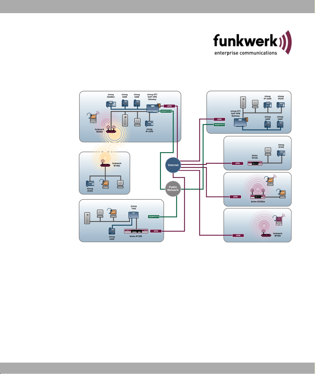
1.1 Possible Applications
Connecting networks
Gateways are used to interconnect networks and to exchange information between the networks. For example, you can use your device to establish a connection to the network of
your Internet Service Provider and use the usual Internet services, such as the World Wide
Web (WWW) or e-mail.
Access to head office
By connecting to another partner network, e.g. your company’s head office, from your
home or branch office, you can conveniently access any information you may need from
the head office, even if this is hundreds of miles away. These local networks are connected
via an ISDN (only bintec R232a, R232b and R232bw) or DSL connection. The size of your
own local network – whether it consists of several computers or just one workstation – is irrelevant.
Your gateway is your link to the outside world
Every device serves as a link between the individual local networks. Within each LAN, the
gateway is connected to the network like a normal computer. Its task is to transmit information as necessary from its own network to an external network (e.g. to the network of your
Internet Service Provider or your head office) and to find the most suitable routes for transmission. Conversely, it receives information and routes it to its own network.
One gateway for everyone
If you have a local network with several computers, you only need one single gateway to
allow all computers in the network access to the Internet or the head office. The lower expenditure on equipment and administration for several computers in the network means
substantial savings. If you used ISDN cards or modems, every workplace would have to be
equipped separately.
2 bintec R200 Series
Page 15

Funkwerk Enterprise Communications GmbH
High-speed Internet access
If you configure high-speed Internet access with the bintec gateway, all the users in the
local network profit from faster Internet access. The bandwidth used permits considerably
faster Internet applications than conventional ISDN or modems.
Automatic dialling and disconnection
Once configured, your device decides independently if and how it is to set up a connection
to the Internet Service Provider. If you enter an external WWW address in your browser, for
example, your gateway determines that the requested address lies outside your own LAN
and establishes a connection to your Internet Service Provider and the Internet automatically. To help you save costs, your gateway disconnects the connection after a predefined
time (short hold) if no more information is exchanged.
Simple data access
If suitably configured, your device enables you to conveniently access data at another site,
e.g. your head office. While running Windows, for example, you can connect a network
drive to a computer at your head office. You then simply click the icon for this link in Windows Explorer and can surf in the directories and data of the remote computer just as if you
were using your own hard disk. Your gateway takes care of setting up and clearing the connection.
1 Introduction
Security/firewall/DynDNS
Your gateway is provided with integrated firewall mechanisms and therefore provides extensive, low-cost features to meet all the requirements for access security. It protects your
network against unauthorised external access. This is achieved with functions such as
NAT, encryption, filters, monitoring and a Stateful Inspection Firewall.
The Stateful Inspection Firewall (SIF) offers effective protection against attacks from the Internet through dynamic packet filtering. Firewall handling is made easier through numerous
pre-configured services. To be able to find partners in spite of dynamic IP addresses, the
devices support the DynDNS function. The implemented function enables you to use the
DynDNS service of leading DynDNS providers, and some providers have been preset. The
security features of the device also include optional web filtering (there is an extra charge
for this, 30-day test version included). Here, all the outgoing Internet enquiries are classified, allowing unwanted contents to be reliably filtered out.
Other security features
With the scheduling function of the devices, times can be defined in which users are granted individual rights, such as for Internet access. The VLAN function of the devices allows
the allocation of users to virtual subnetworks and offers an additional degree of security.
DMZ
bintec R200 Series 3
Page 16

1 Introduction Funkwerk Enterprise Communications GmbH
All devices offer the possibility of configuring a "Demilitarised Zone" (DMZ). This is a separate network located between the internal LAN and the Internet. The DMZ is the place for all
services that have to make direct contact with the Internet. If a web or mail server in the
DMZ is attacked, this has no effect on the security of your internal network.
IP Telephony
The application level gateway allows IP telephones in the LAN to establish a connection
with SIP providers without neglecting the security of the WAN connection. To do this, the
SIP proxy monitors the signalling process between IP telephone and SIP provider and
makes the necessary NAT and firewall releases dynamically for the duration of the communication.
Wireless LAN
The wireless interface of the bintec R230aw and bintec R230bw transfers the data at
max. 54 mbps (802.11g) and is compatible with the 11 mbps variant 802.11b in the same
frequency range. Encryption via the WLAN interface can take place via WPA and WPA2.
Virtual WLAN interfaces can be defined via multi-SSID. This means that different rules of
access to the WLAN can be implemented, e.g. to log in internal personnel and external visitors. The Express Setup Wizard is used for simple WLAN configuration.
IPSec
Both devices have a powerful IPSec implementation and have with two active VPN tunnel
licenses ex works. In addition to encryption via AES or 3DES, the devices offer authentication via certificates or preshared keys. In order to optimise the encrypted traffic flow, it can
be compressed using IPComp. The Dead Peer Detection function allows the availability of
the tunnel endpoint to be checked and restores it if inactive. NAT Traversal is also supported, as is the connection of RADIUS or TACACS+ for authentication.
Configuration and maintenance
A number of options are available for configuring your gateway. Configuration with the Express Setup Wizard, Funkwerk Configuration Interface or Setup Tool is independent of
the operation system. The easiest way to configure the device is by using the Express
Setup Wizard. This configuration assistant guides you through the configuration step by
step and helps you to make the most important settings on your device. Your device is
ready for operation in just a few minutes.
Remote maintenance
The bintec R230a, bintec R230b and bintec R230bw models can also be configured and
maintained remotely. As soon as your device is connected to the ISDN - even in its ex
works state - configuration settings can be made from another location (e.g. by the administrator at head office). This means you can have someone at head office configure the
4 bintec R200 Series
Page 17

Funkwerk Enterprise Communications GmbH
system.
Models
The bintec R230a and bintec R230aw are the successors to the X2301/X2301w gate-
ways. The bintec R232bw second generation includes the first device without a WLAN
function, namely new model bintec R232b.
All four models offer the same features as their predecessors, plus hardware and software
enhancements.
Extra memory and new software features make these devices flexible IP access routers
with an integrated ADSL modem (R232a/aw with annex A, R232b/bw with annex B) and
4-port switch. The support of ADSL2+ allows a high-performance WAN connection and permits download rates of up to 24 mbps. A SIP Proxy controls the transparent communication
with SIP providers, so that the device can be used in VoIP scenarios such as Internet telephony.
bintec R230aw and bintec R230bw also offer WLAN functionality. The WLAN function allows flexible use in wireless environments.
1 Introduction
In addition to a 4-port switch and a further Ethernet port for the LAN/WAN connection, the
bintec R230b and bintec R230bw have an ISDN interface for automatic backup or remote
dial-in.
1.2 About this Manual
Area of validity
This document is valid for bintec devices with system software as of software version
7.8.1.
The bintec user's guide consists of two separate parts: the Reference, and the Workshops.
The guide, which you have in front of you, contains the following chapters:
User's Guide - Reference
Chapter Description
Quick Install Guide This contains instructions for how to set up and start up your
device and create a basic configuration in just a few minutes using the Express Setup Wizard (see Quick Install Guide on
page 8).
Technical data This section contains a description of all the device's technical
bintec R200 Series 5
Page 18

1 Introduction Funkwerk Enterprise Communications GmbH
Chapter Description
properties.
Access and configuration
System administration
Physical interfaces
LAN
Wireless LAN
Routing
WAN
VPN
Firewall
VoIP
Local services
Maintenance
External Reporting
This includes explanations about the different access and configuration methods.
These chapters describe all configuration options of the Funk-
werk Configuration Interface. The chapters are arranged in
the same sequence as the navigation menus in the Funkwerk
Configuration Interface.
The individual chapters also contain general explanations on
the subsystem in question.
Monitoring
Glossary The glossary contains a reference to the most important tech-
nical terms used in network technology.
Index The index lists all the key terms for operating the device and all
the configuration options and gives page numbers so they can
be found easily.
To help you locate information easily, this manual uses the following visual aids:
List of visual aids
Visual aid Use
Identifies general and important points.
6 bintec R200 Series
Page 19

Funkwerk Enterprise Communications GmbH
Visual aid Use
The following typographical elements are used to help you find and interpret the information in this manual:
Typographical elements
Typographical element Use
1 Introduction
Indicates a warning of risk level "Attention" (points out possible
dangers that may cause damage to property if not observed).
Indicates a warning of risk level "Warning" (points out possible
dangers that may cause physical injury or even death if not observed).
•
Menu->Submenu
File->Open
non-proportional
(Courier),
e.g. ping
192.168.1.254
bold, e.g. Windows
Start menu
bold, e.g. biboAdmLoginTable
italic, e.g. none Indicates values that you enter or that can be configured.
Online: blue and italic,
e.g.
www.funkwerk-ec.com
Indicates lists.
Indicates menus and sub-menus.
Indicates commands that you must enter as written.
Indicates keys, key combinations and Windows terms.
Indicates fields.
Indicates hyperlinks.
bintec R200 Series 7
Page 20

2 Quick Install Guide Funkwerk Enterprise Communications GmbH
Chapter 2 Quick Install Guide
This chapter explains how you set up and start up your device and how you create a basic
configuration in just a few minutes using the Express Setup Wizard.
2.1 Introduction
Your bintec gateway contains extensive features for encrypted data transfer and Internet
access for both individual users and companies.
The basic configuration of your device is carried out using the Express Setup Wizard.
The way to obtain the basic configuration is explained below step-by-step. Detailed knowledge of networks is not necessary. A detailed online help system gives you extra support.
The Companion CD also supplied includes all the tools that you need for the configuration
and management of your device.
The BRICKware contains useful applications for managing your device.
2.2 System requirements
For configuration, your PC must meet the following system requirements:
• Windows 95, Windows 98, Windows ME or Windows NT 4.0 or Windows 2000 or Windows XP.
(The instructions for testing/installing the TCP/IP protocol and setting up the PC apply to
Windows 2000 or Windows XP.)
• Installed network card (Ethernet)
• CD ROM drive
• Microsoft TCP/IP protocol installed (see Configuring a PC on page 17)
• High colour display (more than 256 colours) for correct representation of the graphics
2.3 Presettings
Preconfigured data
Your device is shipped with a pre-defined IP configuration:
8 bintec R200 Series
Page 21
Funkwerk Enterprise Communications GmbH
• IP Address: 192.168.0.254
• Netmask: 255.255.255.0
Use the following access data to configure your device as delivered:
• User Name: admin
• Password: funkwerk
Note
All bintec devices are delivered with the same username and password. As long as
the password remains unchanged, they are not protected against unauthorised use.
Make sure you change the passwords to prevent unauthorised access to your device
(see Access and Configuration on page 51).
Software update
Your device contains the version of the system software available at the time of production.
More recent versions may have since been released.
2 Quick Install Guide
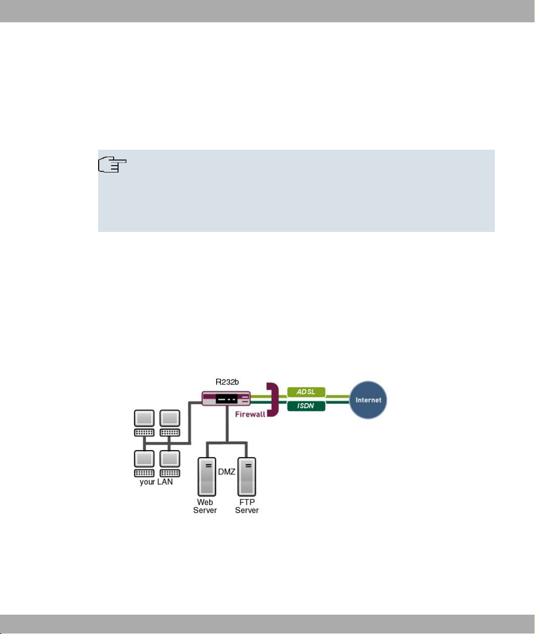
2.4 Installation
Your gateway offers a number of connection options:
Fig. 2: Basic scenario bintec R232a / R232b
bintec R200 Series 9
Page 22
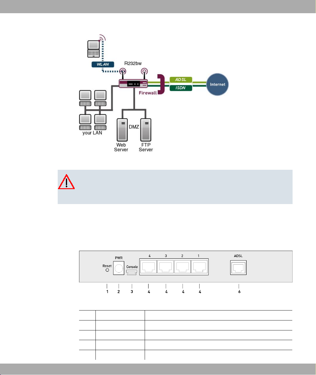
2 Quick Install Guide Funkwerk Enterprise Communications GmbH
Fig. 3: Basic scenario bintec R232bw
Caution
Please read the safety precautions carefully before installing and starting up your
device. These are supplied with the device.
2.4.1 Connections
All connections are located on the back of the device.
Fig. 4: Back of bintec R230a / R230b
1 Reset Reset button
2 PWR Socket for plug-in power pack
3 Console Serial interface
4 4/3/2/1 10/100 Base-T Ethernet interface
6 ADSL ADSL interface (annex A)
10 bintec R200 Series
Page 23
Funkwerk Enterprise Communications GmbH
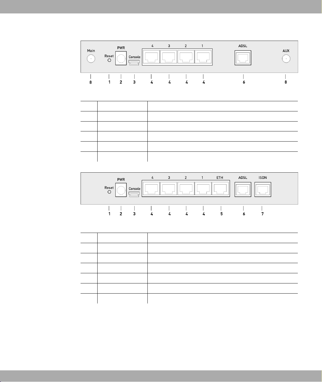
Fig. 5: Back of bintec R230aw
1 Reset Reset button
2 PWR Socket for plug-in power pack
3 Console Serial interface
4 4/3/2/1 10/100 Base-T Ethernet interface
6 ADSL ADSL interface (annex A)
8 Main/AUX RSMA connection
2 Quick Install Guide
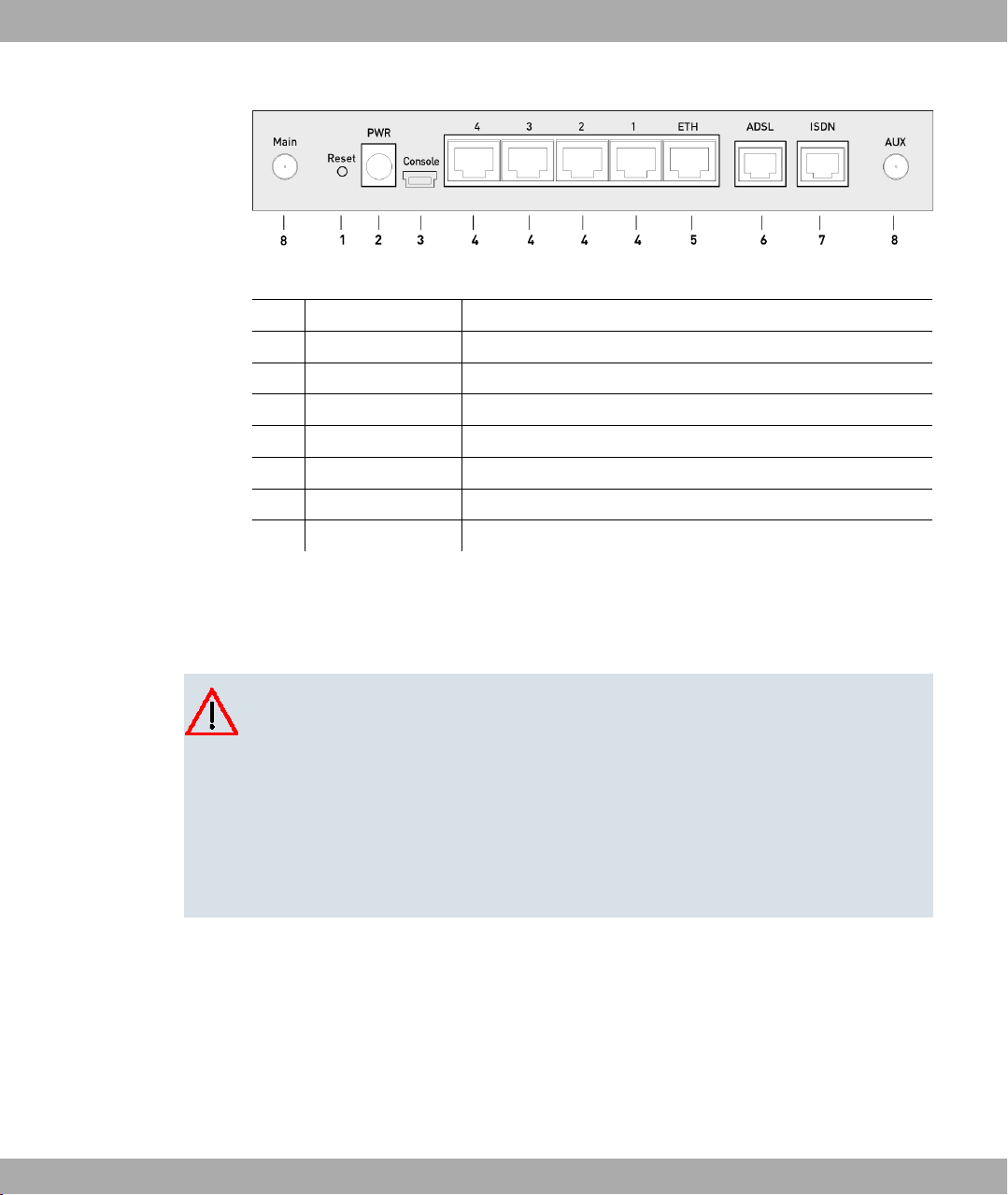
Fig. 6: Back of bintec R232a / R232b
1 Reset Reset button
2 PWR Socket for plug-in power pack
3 Console Serial interface
4 4/3/2/1 10/100 Base-T Ethernet interface
5 ETH Ethernet interface
6 ADSL ADSL interface (annex B)
7 ISDN ISDN interface
bintec R200 Series 11
Page 24
2 Quick Install Guide Funkwerk Enterprise Communications GmbH
Fig. 7: Back of bintec R232bw
1 Reset Reset button
2 PWR Socket for plug-in power pack
3 Console Serial interface
4 4/3/2/1 10/100 Base-T Ethernet interface
5 ETH Ethernet interface
6 ADSL ADSL interface (annex B)
7 ISDN ISDN interface
8 Main/AUX RSMA connection
2.4.2 Setting up and connecting
All you need for this are the cables and antennas supplied with the equipment.
Caution
The use of the wrong mains adapter may damage your device. Only use the mains adaptor supplied with the equipment. If you require foreign adapters/mains units, please
contact our funkwerk service.
Incorrect cabling of the ISDN and ETH interfaces may also damage your device. Connect only the ETH interface of the device to the LAN interface of the computer/hub or a
WAN interface if available and the ISDN interface of the device only to the ISDN connection.
Set up and connect in the following sequence:
(1) Antennas: Screw the two external standard antennas provided to their RSMA connec-
tions (only bintec R230aw and bintec R232bw).
(2) Place your device on a solid, level base.
(3) LAN: For the standard configuration of your device via Ethernet, connect the first
switch port (1) of your device to your LAN using the Ethernet cable supplied. The
device automatically detects whether it is connected to a switch or directly to a PC.
(4) ADSL: Connect the ADSL interface (ADSL) of your device to the DSL output of the
12 bintec R200 Series
Page 25

Funkwerk Enterprise Communications GmbH
splitter using the DSL cable supplied.
(5) Mains connection: Connect the device to a mains socket using the mains adaptor sup-
plied.
Optional connections
• ISDN: Connect the ISDN interface (ISDN) of the device to your ISDN socket using the
ISDN cable provided (only bintec R232a, bintec R232b and bintec R232bw).
• DMZ: Connect the WAN interface (ETH) of your device to the Ethernet connection of
your DMZ using another Ethernet cable (only bintec R232a, bintec R232b and bintec
R232bw).
• Other LANs/WANs: Connect any other terminals in your network to the remaining switch
ports (2, 3 or 4) of your device using other Ethernet cables.
• Setting up a serial connection: For alternative configuration possibilities, connect the serial interface of your PC (COM1 or COM2) to the serial interface of the gateway (console).
Use only the serial cable supplied with the equipment. However, configuration via the
serial interface is not provided by default.
The device is now prepared for configuration using the Express Setup Wizard.
2 Quick Install Guide
2.5 Configuration
In this chapter, you will learn how to prepare the configuration, carry out the configuration,
make adjustments to the PC configurations in the network if necessary and test the connection when the configuration has been completed.
2.5.1 Preparations
To prepare for configuration, you need to...
• have the data for the basic configuration and the Internet connection to hand and also
gather the data needed for connecting the required WLAN clients.
• check whether the PC from which you want to perform the configuration meets the necessary requirements.
You can also...
• install the BRICKwaresoftware, which provides more tools for working with your device.
This installation is optional and not essential for the configuration or operation of the
device.
bintec R200 Series 13
Page 26

2 Quick Install Guide Funkwerk Enterprise Communications GmbH
2.5.1.1 Gathering data
You can gather the main data for basic configuration with the Express Setup Wizard
quickly, as you do not require any information that needs in-depth network knowledge. If
necessary, you can use the example values.
Before you start the configuration, you should gather the data for the following purposes:
• Basic configuration (obligatory if your device is in the ex works state)
• Internet access (optional)
• Wireless LAN (optional, only for bintec R230aw and bintec R232bw)
• Company network connection (optional).
The following tables show examples of possible values for the necessary data. You can
enter your personal data in the "Your values" column, so that you can refer to these values
later when needed.
If you configure a new network, you can use the given example values for IP addresses
and netmasks. In cases of doubt, ask your system administrator.
Basic configuration
For a basic configuration of your gateway, you need information that relates to your network environment:
Basic information
Access data Example value Your values
IP address of your gateway 192.168.0.254
Netmask of your gateway 255.255.255.0
Internet access
If you want to set up Internet access, you need an Internet Service Provider (ISP). You also
receive your personal access data from your ISP. The terms used for the required access
data may vary from provider to provider, but the type of information you need for dialling in
is basically the same.
The following table lists the access data that your device also needs for a DSL connection
to the Internet.
Data for Internet access
Access data Example value Your values
Provider name GoInternet
14 bintec R200 Series
Page 27
Funkwerk Enterprise Communications GmbH
Access data Example value Your values
Protocol PPP over Ethernet
Encapsulation bridged-no-fcs
VPI (Virtual Path Identifier) 1
VCI (Virtual Circuit Identifier) 32
Your user name MyName
Password TopSecret
Some Internet Service Providers, such as T-Online, require additional information:
Additional information for T-Online
Access data Example value Your values
User account (12 digits) 000123456789
T-Online number (usually 12 digits) 06112345678
Joint user account 0001
2 Quick Install Guide
(PPPoE)
Note
To configure T-Online Internet access, in the Username field, enter the following succession of numbers without intervening spaces: User account (12 digits) + T-Online
number (usually 12 digits) + co-user number (for the main user, always 0001). If your
T-Online number is less than 12 digits long, a "#" character is required between the TOnline number and the co-user number. If you use T-DSL, you must add the character
string "@t-online.de" at the end of this string of numbers. You username could, for example, look like this: 00012345678906112345678#0001@t-online.de
Wireless LAN (only bintec R230aw and bintec R232bw)
You can operate your device as an access point and therefore connect individual work stations (e.g. laptops, PCs with wireless card or wireless adapter) by wireless connections to
your local network via WLAN (Wireless LAN) and let them communicate with each other.
The "Data for gateway configuration" table shows the details that are needed to do this.
As data can be transmitted over the air in the WLAN, this data can in theory be intercepted
and read by any attacker with the appropriate resources. Particular attention must therefore
be paid to protecting the wireless connection.
Note the following:
• Follow the security instructions when configuring your WLAN.
bintec R200 Series 15
Page 28

2 Quick Install Guide Funkwerk Enterprise Communications GmbH
• Please also read Sicherheit im Funk-LAN [Security in Wireless LAN] published by the
Federal Office for Information Security, see http://www.bsi.bund.de .
Data for the Wireless LAN configuration
Access data Example value Your values
Preshared key for WPA-PSK without default
Installation location of your system Germany
Channel to be used for WLAN 11
Network name (SSID) for your
WLAN
without default
Visibility of the SSID in the wireless
network
Security setting WPA-PSK
Company network connection
To connect a remote network (e.g. head office), you need to know some data of the remote
terminal that will take your call. The remote terminal must also know your details. You have
to agree this data between you.
Your device and the device at your head office check before every connection to see if they
should take the call from the partner. To protect the network against unauthorised access,
the call is accepted only after correct authentication. This authentication is based on a common password and two codes that you and your partner use for the connection.
Data for connection to a company network
Access data Example value Your values
Partner name
(Key of company head office)
Dial-in number:
not visible
BigBoss
0911987654321
(Call number of the company head
office's device)
Local name
(Your own code. Your partner (the
head office) must enter this name
LittleIndian
16 bintec R200 Series
Page 29

Funkwerk Enterprise Communications GmbH
Access data Example value Your values
as the partner name on its device.)
2 Quick Install Guide
Password
(Common password for this connection, entered on both devices.)
Network address(es) of the company head office
Netmask(s) of the company head
office
Secret
10.1.1.0
255.255.255.0
2.5.1.2 Configuring a PC
In order to reach your device via the network and to be able to carry out configuration using
the Express Setup Wizard, the PC used for the configuration has to satisfy some pre-
requisites.
• Make sure that the TCP/IP protocol is installed on the PC.
• Assign fixed IP address to your PC.
Checking the TCP/IP protocol
Proceed as follows to check whether you have installed the protocol:
(1) Click the Windows Start button and then Settings -> Network and Dial-up Connec-
tions (Windows 2000) or Settings -> Network Connections (Windows XP).
(2) Click LAN Connection.
(3) Click Properties in the status window.
(4) Look for the Internet Protocol (TCP/IP) entry in the list of network components.
Installing the TCP/IP protocol
If you cannot find the Internet Protocol (TCP/IP) entry, install the TCP/IP protocol as fol-
lows:
(1) First click Properties, then Install in the status window of the LAN Connection.
(2) Select the Protocol entry.
(3) Click Add.
(4) Select Internet Protocol (TCP/IP) and click OK.
(5) Follow the on-screen instructions and restart your PC when you have finished.
bintec R200 Series 17
Page 30

2 Quick Install Guide Funkwerk Enterprise Communications GmbH
Allocating PC IP address
Allocate an IP address to your PC as follows:
(1) Select Internet Protocol (TCP/IP) and click Properties.
(2) Choose Use next IP address and enter a suitable IP address.
Your PC should now satisfy all the prerequisites for the configuration of your device.
Entering the gateway IP address in your PC
Then continue by entering the IP address of the gateway in the configuration of your PC as
follows:
(1) In Internet Protocol (TCP/IP) -> Properties under Default gateway, enter the IP ad-
dress of your gateway. If you do not use the pre-configured IP address of the gateway
or have not yet defined an IP address for it, carry out the initial gateway configuration
steps first (see Configuring the Gateway on page 20). You can determine a free IP ad-
dress in your network automatically. Enter this IP address here.
(2) Enter the IP address of your device under Use next DNS server address.
(3) Click OK.
(4) Close the status window with OK.
The computer now has an IP configuration and can access the Internet via the gateway.
2.5.1.3 Installing BRICKware
BRICKware contains a number of programs to help you when working with your device.
The installation is optional.
You only need the Companion CD supplied with your device for the installation. Your PC
should also meet the prerequisites stated in Introduction on page 8.
Elements of BRICKware
Tool Description
Activity Monitor The Activity Monitor ensures permanent monitoring of the data
transmitted on your device. It also allows the administrator of
the device to control, under password protection, individual interfaces and connections specifically using certain commands,
e.g. establishing and clearing connections or changing preconfigured Internet providers.
SNMP Manager The SNMP Manager provides you with complete access to your
device's configuration. With this application, you can monitor important device events at the same time (SNMP traps).
18 bintec R200 Series
Page 31

Funkwerk Enterprise Communications GmbH
Tool Description
Dime Tools The Dime Tools application provides a number of services.
To install the software, proceed as follows:
(1) Close all Windows programs on your PC.
(2) Place your bintec Companion CD in the CD-ROM drive of your PC. The Start win-
dow will appear automatically after a short time. If the Start window does not open
automatically, click your CD-ROM drive in Windows Explorer and double-click
setup.exe. (For Unix computers: Open the index.htm file in your standard browser.)
(3) In Add Ons, click BRICKware. A screen will then appear via which you can start the
installation or display the descriptions of the BRICKware components. Click the but-
ton to start the Setup program.
(4) Specify the directory in which the BRICKware is to be installed.
(5) Select your device.
(6) Select the software components you wish to install.
2 Quick Install Guide
Tasks of the individual services:
• Updating of the system software: TFTP server
• Saving of the configuration on the PC: TFTP server
• Time synchronisation of the device with the server: Time server
• Saving of messages and data for accounting, sent from the
device: Syslog Daemon
• The processes can be logged if there are problems with the
data communications: ISDN Tracer
• Assignment of IP addresses and loading of configurations:
BootP server
The installed programs are available for use immediately after the installation of the
BRICKware; it is not usually necessary to reboot the PC.
bintec R200 Series 19
Page 32

2 Quick Install Guide Funkwerk Enterprise Communications GmbH
2.5.2 Configuring the Gateway
Your gateway can be configured quickly and easily with the Express Setup Wizard.
Fig. 8: Express Setup Wizard - Initial Screen
If you have already created a configuration using the Express Setup Wizard, the Express
Setup Wizard can use the preset values. You will be informed about this possibility during
configuration.
Start the configuration of your gateway as follows:
(1) Enter http://192.168.0.254/wizard or https://192.168.0.254/wizard in
your web browser's address line. Follow the instructions.
Optional:
(1) On the bintec bintec Companion CD, choose Installation, and click the Configure
Device button.
(2) Then follow the instructions to find a free IP address for the device. Click Allocate
Automatically... or enter the IP address and network mask you have defined.
(3) Start the configuration withComplete.
You can carry out the configuration in Quick or Advanced mode. If you are not very familiar with networking technologies, choose Quick. Your device is ready for operation when
you have completed the configuration.
You can select from the following configuration items:
20 bintec R200 Series
Page 33

Funkwerk Enterprise Communications GmbH
• Basic configuration
• Internet connection
• WLAN settings
• Corporate network connection (LAN-LAN coupling).
The basic configuration is essential if your device is still in the ex works state, as it integrates the gateway into your local network.
(1) Select the desired items and follow the instructions on the screen.
(2) To be able to use your device in your local network, it may be necessary to make a
few more settings on the PCs connected in the network after completing the configuration. You can set up Internet access over your device for all PCs in the same network
as your device. To do this, you should set up these PCs as DHCP clients. Otherwise,
you have to allocate a fixed IP address to each PC and enter your device as a default
gateway and as a DNS server (see Configuring a PC on page 17).
The configuration of the gateway and its integration into your network are now completed.
2.5.3 Testing the Configuration
2 Quick Install Guide
You have completed the configuration of your device and can now test the connection in
your LAN and to the Internet.
Carry out the following steps to test your device:
(1) Remove the serial cable from your device if this was connected and you no longer
need the serial connection.
(2) Test the connection to your device. Click Run in the Start menu and enter ping, fol-
lowed by a space and the IP address of your device (e.g. 192.168.0.254). A window appears with the response "Reply from...".
(3) Test Internet access by entering www.funkwerk-ec.com in the Internet browser. Funk-
werk Enterprise Communications GmbH's Internet site offers you the latest news, updates and documentation.
Note
Incorrect configuration of the devices in your LAN may result in unwanted connections
and increased charges! Monitor your device and make sure it only sets up connections
at the times you want it to. Watch the LEDs on your device (LED ISDN, ADSL and Ethernet interfaces to which you have connected one or more WANs; for an explanation
of the displays, see Technical data on page 24) or use the Activity Monitor (see
BRICKware for Windows).
bintec R200 Series 21
Page 34

2 Quick Install Guide Funkwerk Enterprise Communications GmbH
2.5.4 Reset
If the configuration is incorrect or if your device cannot be accessed, you can reset the
device to the ex works standard settings using the Reset button on the back of the device.
Practically al existing configuration data will then be ignored, only the current user passwords are retained. Configurations stored in the device are not deleted and can, if required,
be reloaded when the device is rebooted.
Proceed as follows:
(1) Switch off your device.
(2) Press the Reset button on your device.
(3) Keep the Reset button on your device pressed down and switch the device back on.
(4) Look at the LEDs:
- The Power and Status LEDs come on first.
- The Ethernet LEDs ( 1 to 4 ) for the ports connected to the Ethernet then flash.
The device runs through the boot sequence.
- After the Status LED has flashed five times, release the Reset button.
Proceed as follows if you also want to reset all the user passwords to the ex works state
and delete stored configurations when resetting the device:
(1) Set up a serial connection to your device. Reboot your device and monitor the boot
sequence. Start the BOOTmonitor and choose (4) Delete Configuration and following the instructions.
or
(2) Set up a serial connection to your device. First carry out the reset procedure de-
scribed and enter erase bootconfig as Login at the login prompt in the command
line. Leave the password empty and press Return. The device runs through the boot
sequence again.
Note
If you delete the boot configuration using the Funkwerk Configuration Interface, all
passwords will also be reset and the current boot configuration deleted. The next time,
the device will boot with the standard ex works settings.
You can now configure your gateway again as described as of Configuring the Gateway on
page 20.
22 bintec R200 Series
Page 35

Funkwerk Enterprise Communications GmbH
2.6 Support Information
If you have any questions on your new product or would like more information, you can
reach the Support Center of Funkwerk Enterprise Communications GmbH under the following call number or via the E-mail Hotline:
+49 911 9673 1550
hotline@funkwerk-ec.com
For detailed information on our support services, contact www.funkwerk-ec.com.
2 Quick Install Guide
bintec R200 Series 23
Page 36

3 Technical data Funkwerk Enterprise Communications GmbH
Chapter 3 Technical data
This chapter provides a summary of all the hardware properties of the R230a, R230b,
R230aw, R232a, R232b and R232bw devices.
3.1 bintec R230a / bintec R230b
3.1.1 Scope of supply
Your device is supplied with the following parts:
• Cable sets/mains unit:
- Ethernet cable
- Serial connecting cable
- DSL cable
- Plug-in power pack
• bintec Companion CD
• Documentation:
- Quick Install Guide (printed)
- User's Guide (on CD)
- Release Notes, if required
- Safety precautions
3.1.2 General Product Features
The general product features cover performance features and the technical prerequisites
for installation and operation of your device.
The features are summarised in the following table:
General Product Features
Property Value
Product name bintec R230a / bintec R230b
24 bintec R200 Series
Page 37

Funkwerk Enterprise Communications GmbH
Property Value
Dimensions and
weights:
3 Technical data
Equipment dimensions
without cable (B x H x
D):
Weight approx. 550 g
Transport weight (incl.
documentation, cables,
packaging)
Memory 32 MB SDRAM,
LEDs 11 (1x Power, 4x2 Ethernet, 1x Status, 1x ADSL)
Power consumption of
the device
Voltage supply 12 V DC 500 mA EU PSU
Environmental requirements:
158 mm x 25.7 mm x 123.1 mm
approx. 1.2 kg
8 MB flash ROM
4.7 Watt
Storage temperature -20° to +70 °C
Operating temperature 0° to 40 °C
Relative atmospheric humidity
Room classification Only use in dry rooms.
Available interfaces:
ADSL interface Internal ADSL modem for Annex A (R230a) and Annex B
10 % to 90 % non-condensing in operation,
5 % to 95 % non-condensing when stored
(R230b)
bintec R200 Series 25
Page 38

3 Technical data Funkwerk Enterprise Communications GmbH
Property Value
Serial interface V.24 Permanently installed, supports Baud rates: 1200, 2400, 4800,
9600, 19200, 38400, 57600, 115200 Baud
Ethernet IEEE 802.3
LAN (4-port switch)
Available sockets:
Serial interface V.24 5-pole mini USB socket
Ethernet interface RJ45 socket
ADSL interface RJ11 socket
Standards & Guidelines R&TTE Directive 1999/5/EC
SAFERNET TM Security
Technology
Software supplied BRICKware for Windows
Printed documentation
supplied
Permanently installed (twisted pair only), 10/100 mbps, autosensing, MDIX
CE symbol for all EU states
Community Passwords, PAP, CHAP, MS-CHAP, Access Control Lists, NAT, SIF
BRICKtools for Unix
Quick Install Guide
Online documentation User's Guide
BRICKware for Windows (Engl.)
Software Reference (Engl.)
3.1.3 LEDs
The device LEDs provide information on certain activities and statuses of the device.
They are arranged as follows:
26 bintec R200 Series
Page 39

Funkwerk Enterprise Communications GmbH
Fig. 9: LEDs on bintec R230a / bintec R230b
In operating mode, the LEDs display the following status information for your device:
LED status display
LED Status Information
Power on The power supply is connected.
Status on The device has started.
flashing The device is active.
3 Technical data
1 to 4 on The device is connected to the Ethernet (100 mbps or 10
mbps).
flashing Data traffic via the Ethernet Interface (100 mbps or 10 mbps).
ADSL on ADSL connection is active.
3.1.4 Connections
All the connections are located on the back of the device. bintec R230a and bintec R230b
has a 4-port Ethernet switch, an ADSL interface and a serial interface.
The connections are arranged as follows:
Fig. 10: Back of bintec R230a / R230b
bintec R200 Series 27
Page 40

3 Technical data Funkwerk Enterprise Communications GmbH
Back of bintec R230a / bintec R230b
1 Reset Reset button
2 PWR Socket for plug-in power pack
3 Console Serial interface
4 4/3/2/1 10/100 Base-T Ethernet interface
6 ADSL ADSL interface
3.1.5 Pin Assignments
3.1.5.1 Serial Interface
bintec R230a and bintec R230b have a serial interface for connection to a console. This
supports Baud rates from 1200 to 115200 Bps.
The interface is designed as a 5-pole mini USB socket.
Fig. 11: 5-pole mini USB socket
The pin assignment is as follows:
Pin assignment of the mini USB socket
Pin Function
1 Not used
2 Rx
3 GND
4 Not used
5 Tx
3.1.5.2 Ethernet interface
bintec R230a and bintec R230b have an Ethernet interface with an integrated 4-port
switch. This is used to connect individual PCs or other switches.
The connection is made via an RJ45 socket.
28 bintec R200 Series
Page 41

Funkwerk Enterprise Communications GmbH
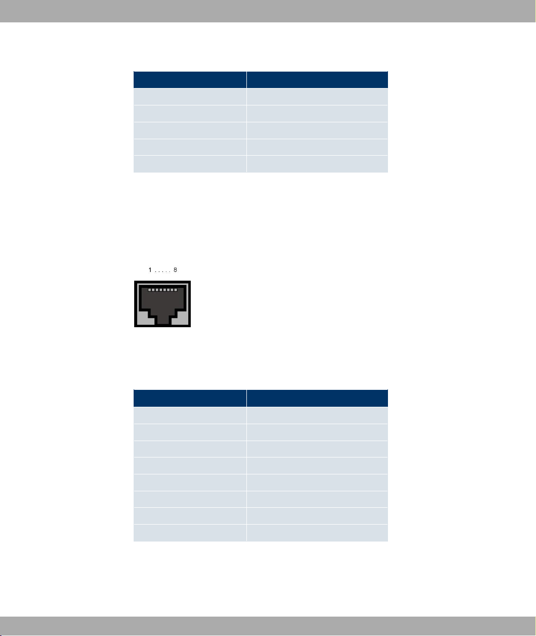
Fig. 12: Ethernet 10/100 Base-T interface (RJ45 socket)
The pin assignment for the Ethernet 10/100 Base-T interface (RJ45 socket) is as follows:
RJ45 socket for LAN connection
Pin Function
1 TD +
2 TD -
3 RD +
4 Not used
5 Not used
6 RD -
7 Not used
8 Not used
3 Technical data
The Ethernet 10/100 BASE-T interface does not have an Auto-MDI-X function.
3.1.5.3 ADSL interface
The ADSL interface is connected via an RJ11 plug. The cable supplied connects the RJ11
plug needed for the device to an RJ11 plug needed for most ADSL splitters.
Only the two inner pins are used for the ADSL connection:
Fig. 13: ADSL interface (RJ11)
The pin assignment for the ADSL interface (RJ11 socket) is as follows:
RJ11 socket for ADSL connection
Pin Function
1 Not used
bintec R200 Series 29
Page 42

3 Technical data Funkwerk Enterprise Communications GmbH
Pin Function
2 a
3 b
4 Not used
3.2 bintec R230aw
3.2.1 Scope of supply
Your device is supplied with the following parts:
• Cable sets/mains unit:
- Ethernet cable
- Serial connecting cable
- DSL cable
- Plug-in power pack
• Antennas:
- two standard antennas
• bintec Companion CD
• Documentation:
- Quick Install Guide (printed)
- User's Guide (on CD)
- Release Notes, if required
- Safety precautions
3.2.2 General Product Features
The general product features cover performance features and the technical prerequisites
for installation and operation of your device.
The features are summarised in the following table:
General Product Features
30 bintec R200 Series
Page 43

Funkwerk Enterprise Communications GmbH
Property Value
Product name bintec R230aw
Dimensions and
weights:
3 Technical data
Equipment dimensions
without cable (B x H x
D):
Weight approx. 550 g
Transport weight (incl.
documentation, cables,
packaging)
Memory 32 MB SDRAM,
LEDs 12 (1x Power, 4x2 Ethernet, 1x WLAN, 1x Status, 1x ADSL)
Power consumption of
the device
Voltage supply 12 V DC 800 mA EU PSU
Environmental requirements:
158 mm x 25.7 mm x 123.1 mm
approx. 1.2 kg
8 MB flash ROM
4.7 Watt
Storage temperature -20° to +70 °C
Operating temperature 0° to 40 °C
Relative atmospheric humidity
Room classification Only use in dry rooms.
Available interfaces:
ADSL interface Internal ADSL modem for Annex A
10 % to 90 % non-condensing in operation,
5 % to 95 % non-condensing when stored
bintec R200 Series 31
Page 44

3 Technical data Funkwerk Enterprise Communications GmbH
Property Value
Serial interface V.24 Permanently installed, supports Baud rates: 1200, 2400, 4800,
9600, 19200, 38400, 57600, 115200 Baud
Ethernet IEEE 802.3
LAN (4-port switch)
WLAN interface
(antennas)
Available sockets:
Serial interface V.24 5-pole mini USB socket
Ethernet interface RJ45 socket
ADSL interface RJ11 socket
SAFERNET TM Security
Technology
Software supplied BRICKware for Windows
Printed documentation
supplied
Permanently installed (twisted pair only), 10/100 mbps, autosensing, MDIX
802.11b and 802.11g with Antenna Diversity
Data rates 1, 2, 5.5, 6, 9, 11, 12, 18, 24, 36, 48, 54 mbps 1-, 2-,
5.5-, 6-, 9-, 11-, 12-, 18-, 24-, 36-, 48-, 54 mbps
Community Passwords, PAP, CHAP, MS-CHAP, Access Control Lists, NAT, SIF
BRICKtools for Unix
Quick Install Guide
Online documentation User's Guide
BRICKware for Windows (Engl.)
Software Reference (Engl.)
Note
Antenna Diversity
The two antennas have different functions. One is used both to transmit and receive
(known as the "main" antenna), the other is only used to receive. During reception, the
AP (Access Point) checks which antenna is receiving a better signal. This is then used
32 bintec R200 Series
Page 45

Funkwerk Enterprise Communications GmbH
for decoding. Since the two antennas are approximately one wavelength apart, the difference in signal strength can be quite considerable.
3.2.3 LEDs
The device LEDs provide information on certain activities and statuses of the device.
They are arranged as follows:
Fig. 14: LEDs on bintec R230aw
3 Technical data
In operating mode, the LEDs display the following status information for your device:
LED status display
LED Status Information
Power on The power supply is connected.
Status on The device has started.
flashing The device is active.
1 to 4 on The device is connected to the Ethernet (100 mbps or 10
mbps).
flashing Data traffic via the Ethernet Interface (100 mbps or 10 mbps).
WLAN on The WLAN module is active.
flashing Data traffic via the WLAN interface.
ADSL on ADSL connection is active.
bintec R200 Series 33
Page 46

3 Technical data Funkwerk Enterprise Communications GmbH
3.2.4 Connections
All the connections are located on the back of the device. bintec R230aw has a 4-port Ethernet switch, an ADSL interface and a serial interface.
The connections are arranged as follows:
Fig. 15: Back of bintec R230aw
Back of bintec R230aw
1 Reset Reset button
2 PWR Socket for plug-in power pack
3 Console Serial interface
4 4/3/2/1 10/100 Base-T Ethernet interface
6 ADSL ADSL interface
8 Main/AUX RSMA connection
3.2.5 Pin Assignments
3.2.5.1 Serial interface
bintec R230aw has a serial interface for connection to a console. This supports Baud rates
from 1200 to 115200 Bps.
The interface is designed as a 5-pole mini USB socket.
Fig. 16: 5-pole mini USB socket
The pin assignment is as follows:
34 bintec R200 Series
Page 47
Funkwerk Enterprise Communications GmbH
Pin assignment of the mini USB socket
Pin Function
1 Not used
2 Rx
3 GND
4 Not used
5 Tx
3.2.5.2 Ethernet interface
bintec R230aw has an Ethernet interface with an integrated 4-port switch. This is used to
connect individual PCs or other switches.
The connection is made via an RJ45 socket.
3 Technical data
Fig. 17: Ethernet 10/100 Base-T interface (RJ45 socket)
The pin assignment for the Ethernet 10/100 Base-T interface (RJ45 socket) is as follows:
RJ45 socket for LAN connection
Pin Function
1 TD +
2 TD -
3 RD +
4 Not used
5 Not used
6 RD -
7 Not used
8 Not used
3.2.5.3 ADSL interface
The ADSL interface is connected via an RJ11 plug. The cable supplied connects the RJ11
plug needed for the device to an RJ11 plug needed for most ADSL splitters.
bintec R200 Series 35
Page 48

3 Technical data Funkwerk Enterprise Communications GmbH
Only the two inner pins are used for the ADSL connection.
Fig. 18: ADSL interface (RJ11)
The pin assignment for the ADSL interface (RJ11 socket) is as follows:
RJ11 socket for ADSL connection
Pin Function
1 Not used
2 a
3 b
4 Not used
3.3 bintec R232a / bintec R232b
3.3.1 Scope of supply
Your device is supplied with the following parts:
• Cable sets/mains unit:
- Ethernet cable
- ISDN cable
- Serial connecting cable
- DSL cable
- Plug-in power pack
• bintec Companion CD
• Documentation:
- Quick Install Guide (printed)
- User's Guide (on CD)
36 bintec R200 Series
Page 49

Funkwerk Enterprise Communications GmbH
- Release Notes, if required
- Safety precautions
3.3.2 General Product Features
The general product features cover performance features and the technical prerequisites
for installation and operation of your device.
The features are summarised in the following table:
General Product Features
Property Value
Product name bintec R232a / bintec R232b
Dimensions and
weights:
3 Technical data
Equipment dimensions
without cable (B x H x
D):
Weight approx. 550 g
Transport weight (incl.
documentation, cables,
packaging)
Memory 32 MB SDRAM,
LEDs 13 (1x Power, 4x2 Ethernet, 1x ETH, 1x Status, 1x ADSL, 1x
Power consumption of
the device
Voltage supply 12 V DC 800 mA EU PSU
Environmental requirements:
189,2 mm x 27 mm x 123,1 mm
approx. 1.2 kg
8 MB flash ROM
ISDN)
4.7 Watt
bintec R200 Series 37
Page 50

3 Technical data Funkwerk Enterprise Communications GmbH
Property Value
Storage temperature -20° to +70 °C
Operating temperature 0° to 40 °C
Relative atmospheric humidity
Room classification Only use in dry rooms.
Available interfaces:
ADSL interface Internal ADSL modem for Annex A (R232a) and Annex B
Serial interface V.24 Permanently installed, supports Baud rates: 1200, 2400, 4800,
Ethernet IEEE 802.3
LAN (4-port switch)
ISDN-WAN S0 Permanently installed
ETH Additional Ethernet switch port
Available sockets:
10 % to 90 % non-condensing in operation,
5 % to 95 % non-condensing when stored
(R232b)
9600, 19200, 38400, 57600, 115200 Baud
Permanently installed (twisted pair only), 10/100 mbps, autosensing, MDIX
Serial interface V.24 5-pole mini USB socket
Ethernet interface RJ45 socket
ISDN interface RJ45 socket
ADSL interface RJ11 socket
SAFERNET TM Security
Technology
Software supplied BRICKware for Windows
Community Passwords, PAP, CHAP, MS-CHAP, Access Control Lists, NAT, SIF
BRICKtools for Unix
38 bintec R200 Series
Page 51

Funkwerk Enterprise Communications GmbH
Property Value
3 Technical data
Printed documentation
supplied
Online documentation User's Guide
Quick Install Guide
BRICKware for Windows (Engl.)
Software Reference (Engl.)
3.3.3 LEDs
The device LEDs provide information on certain activities and statuses of the device.
They are arranged as follows:
Fig. 19: LEDs on bintec R232a / bintec R232b
In operating mode, the LEDs display the following status information for your device:
LED status display
LED Status Information
Power on The power supply is connected.
Status on The device has started.
flashing The device is active.
1 to 4 on The device is connected to the Ethernet (100 mbps or 10
mbps).
flashing Data traffic via the Ethernet Interface (100 mbps or 10 mbps).
ETH on The device is connected to the Ethernet.
flashing Data traffic via the Ethernet interface.
bintec R200 Series 39
Page 52

3 Technical data Funkwerk Enterprise Communications GmbH
LED Status Information
ADSL on ADSL connection is active.
ISDN on One B channel is used.
flashing Both B channels are in use.
3.3.4 Connections
All the connections are located on the back of the device. bintec R232a and bintec R232b
havea 4-port Ethernet switch, an ETH interface, an ISDN interface, an ADSL interface and
a serial interface.
The connections are arranged as follows:
Fig. 20: Back of bintec R232a / bintec R232b
Back of bintec R232a / bintec R232b
1 Reset Reset button
2 PWR Socket for plug-in power pack
3 Console Serial interface
4 4/3/2/1 10/100 Base-T Ethernet interface
5 ETH Ethernet interface
6 ADSL ADSL interface
7 ISDN ISDN interface
3.3.5 Pin Assignments
3.3.5.1 Serial interface
bintec R232a and bintec 232b have a serial interface for connection to a console. This
supports Baud rates from 1200 to 115200 Bps.
40 bintec R200 Series
Page 53

Funkwerk Enterprise Communications GmbH
The interface is designed as a 5-pole mini USB socket.
Fig. 21: 5-pole mini USB socket
The pin assignment is as follows:
Pin assignment of the mini USB socket
Pin Function
1 Not used
2 Rx
3 GND
4 Not used
5 Tx
3 Technical data
3.3.5.2 Ethernet interface
bintec R232a and bintec R232b have an Ethernet interface with an integrated 4-port
switch. This is used to connect individual PCs or other switches. The device also has a fifth
Ethernet interface.
The connection is made via an RJ45 socket.
Fig. 22: Ethernet 10/100 Base-T interface (RJ45 socket)
The pin assignment for the Ethernet 10/100 Base-T interface (RJ45 socket) is as follows:
RJ45 socket for LAN connection
Pin Function
1 TD +
2 TD -
3 RD +
4 Not used
bintec R200 Series 41
Page 54

3 Technical data Funkwerk Enterprise Communications GmbH
Pin Function
5 Not used
6 RD -
7 Not used
8 Not used
3.3.5.3 ADSL interface
The ADSL interface is connected via an RJ11 plug. The cable supplied connects the RJ11
plug needed for the device to an RJ11 plug needed for most ADSL splitters.
Only the two inner pins are used for the ADSL connection.
Fig. 23: ADSL interface (RJ11)
The pin assignment for the ADSL interface (RJ11 socket) is as follows:
RJ11 socket for ADSL connection
Pin Function
1 Not used
2 a
3 b
4 Not used
3.3.5.4 ISDN S0 port
bintec R232a and bintec R232b have an additional ISDN-S0 interface, which can be used
for back-up functions, for example.
The connection is made via an RJ45 socket.
Fig. 24: ISDN S0 BRI interface (RJ45 socket)
42 bintec R200 Series
Page 55

Funkwerk Enterprise Communications GmbH
The pin assignment for the ISDN S0 BRI interface (RJ45 socket) is as follows:
RJ45 socket for ISDN connection
Pin Function
1 Not used
2 Not used
3 Transmit (+)
4 Receive (+)
5 Receive (-)
6 Transmit (-)
7 Not used
8 Not used
3.4 bintec R232bw
3 Technical data
3.4.1 Scope of supply
Your device is supplied with the following parts:
• Cable sets/mains unit:
- Ethernet cable
- ISDN cable
- Serial connecting cable
- DSL cable
- Plug-in power pack
• Antennas:
- two standard antennas
• bintec Companion CD
• Documentation:
- Quick Install Guide (printed)
- User's Guide (on CD)
- Release Notes, if required
bintec R200 Series 43
Page 56

3 Technical data Funkwerk Enterprise Communications GmbH
- Security instructions
3.4.2 General Product Features
The general product features cover performance features and the technical prerequisites
for installation and operation of your device.
The features are summarised in the following table:
General Product Features
Property Value
Product name bintec R232bw
Dimensions and
weights:
Equipment dimensions
without cable (B x H x
D):
Weight approx. 550 g
Transport weight (incl.
documentation, cables,
packaging)
Memory 32 MB SDRAM,
LEDs 14 (1x Power, 4x2 Ethernet, 1x ETH, 1x WLAN, 1x Status, 1x
Power consumption of
the device
Voltage supply 12 V DC 800 mA EU PSU
Environmental requirements:
189,2 mm x 27 mm x 123,1 mm
approx. 1.2 kg
8 MB flash ROM
ADSL, 1x ISDN)
4.7 Watt
Storage temperature -20° to +70 °C
44 bintec R200 Series
Page 57

Funkwerk Enterprise Communications GmbH
Property Value
Operating temperature 0° to 40 °C
3 Technical data
Relative atmospheric humidity
Room classification Only use in dry rooms.
Available interfaces:
ADSL interface Internal ADSL modem for Annex B
Serial interface V.24 Permanently installed, supports Baud rates: 1200, 2400, 4800,
Ethernet IEEE 802.3
LAN (4-port switch)
ISDN-WAN S0 Permanently installed
ETH Additional Ethernet switch port
WLAN interface
(antennas)
10 % to 90 % non-condensing in operation,
5 % to 95 % non-condensing when stored
9600, 19200, 38400, 57600, 115200 Baud
Permanently installed (twisted pair only), 10/100 mbps, autosensing, MDIX
802.11b and 802.11g with Antenna Diversity
Data rates 1, 2, 5.5, 6, 9, 11, 12, 18, 24, 36, 48, 54 mbps 1-, 2-,
5.5-, 6-, 9-, 11-, 12-, 18-, 24-, 36-, 48-, 54 mbps
Available sockets:
Serial interface V.24 5-pole mini USB socket
Ethernet interface RJ45 socket
ISDN interface RJ45 socket
ADSL interface RJ11 socket
SAFERNET TM Security
Technology
Software supplied BRICKware for Windows
Community Passwords, PAP, CHAP, MS-CHAP, Access Control Lists, NAT, SIF
bintec R200 Series 45
Page 58

3 Technical data Funkwerk Enterprise Communications GmbH
Property Value
BRICKtools for Unix
Printed documentation
supplied
Online documentation User's Guide
Note
Quick Install Guide
BRICKware for Windows (Engl.)
Software Reference (Engl.)
Antenna Diversity
The two antennas have different functions. One is used both to transmit and receive
(known as the "main" antenna), the other is only used to receive. During reception, the
AP (Access Point) checks which antenna is receiving a better signal. This is then used
for decoding. Since the two antennas are approximately one wavelength apart, the difference in signal strength can be quite considerable.
3.4.3 LEDs
The device LEDs provide information on certain activities and statuses of the device.
They are arranged as follows:
Fig. 25: LEDs on bintec R232bw
In operating mode, the LEDs display the following status information for your device:
LED status display
LED Status Information
Power on The power supply is connected.
46 bintec R200 Series
Page 59

Funkwerk Enterprise Communications GmbH
LED Status Information
Status on The device has started.
flashing The device is active.
1 to 4 on The device is connected to the Ethernet (100 mbps or 10
flashing Data traffic via the Ethernet Interface (100 mbps or 10 mbps).
WLAN on The WLAN module is active.
flashing Data traffic via the WLAN interface.
ETH on The device is connected to the Ethernet.
flashing Data traffic via the Ethernet interface.
3 Technical data
mbps).
ADSL on ADSL connection is active.
ISDN on One B channel is used.
flashing Both B channels are in use.
3.4.4 Connections
All the connections are located on the back of the device. bintec R232bw has a 4-port Ethernet switch, an ETH interface, an ISDN interface, an ADSL interface and a serial interface.
The connections are arranged as follows:
Fig. 26: Back of bintec R232bw
Back of bintec R232bw
1 Reset Reset button
bintec R200 Series 47
Page 60

3 Technical data Funkwerk Enterprise Communications GmbH
2 PWR Socket for plug-in power pack
3 Console Serial interface
4 4/3/2/1 10/100 Base-T Ethernet interface
5 ETH Ethernet interface
6 ADSL ADSL interface
7 ISDN ISDN interface
8 Main/AUX RSMA connection
3.4.5 Pin Assignments
3.4.5.1 Serial interface
bintec R232bw has a serial interface for connection to a console. This supports Baud rates
from 1200 to 115200 Bps.
The interface is designed as a 5-pole mini USB socket.
Fig. 27: 5-pole mini USB socket
The pin assignment is as follows:
Pin assignment of the mini USB socket
Pin Function
1 Not used
2 Rx
3 GND
4 Not used
5 Tx
3.4.5.2 Ethernet interface
The bintec R232bw has an Ethernet interface with an integrated 4-port switch. This is
used to connect individual PCs or other switches. The device also has a fifth Ethernet interface.
The connection is made via an RJ45 socket.
48 bintec R200 Series
Page 61

Funkwerk Enterprise Communications GmbH
Fig. 28: Ethernet 10/100 Base-T interface (RJ45 socket)
The pin assignment for the Ethernet 10/100 Base-T interface (RJ45 socket) is as follows:
RJ45 socket for LAN connection
Pin Function
1 TD +
2 TD -
3 RD +
4 Not used
5 Not used
6 RD -
7 Not used
8 Not used
3 Technical data
3.4.5.3 ADSL interface
The ADSL interface is connected via an RJ11 plug. The cable supplied connects the RJ11
plug needed for the device to an RJ11 plug needed for most ADSL splitters.
Only the two inner pins are used for the ADSL connection.
Fig. 29: ADSL interface (RJ11)
The pin assignment for the ADSL interface (RJ11 socket) is as follows:
RJ11 socket for ADSL connection
Pin Function
1 Not used
2 a
bintec R200 Series 49
Page 62
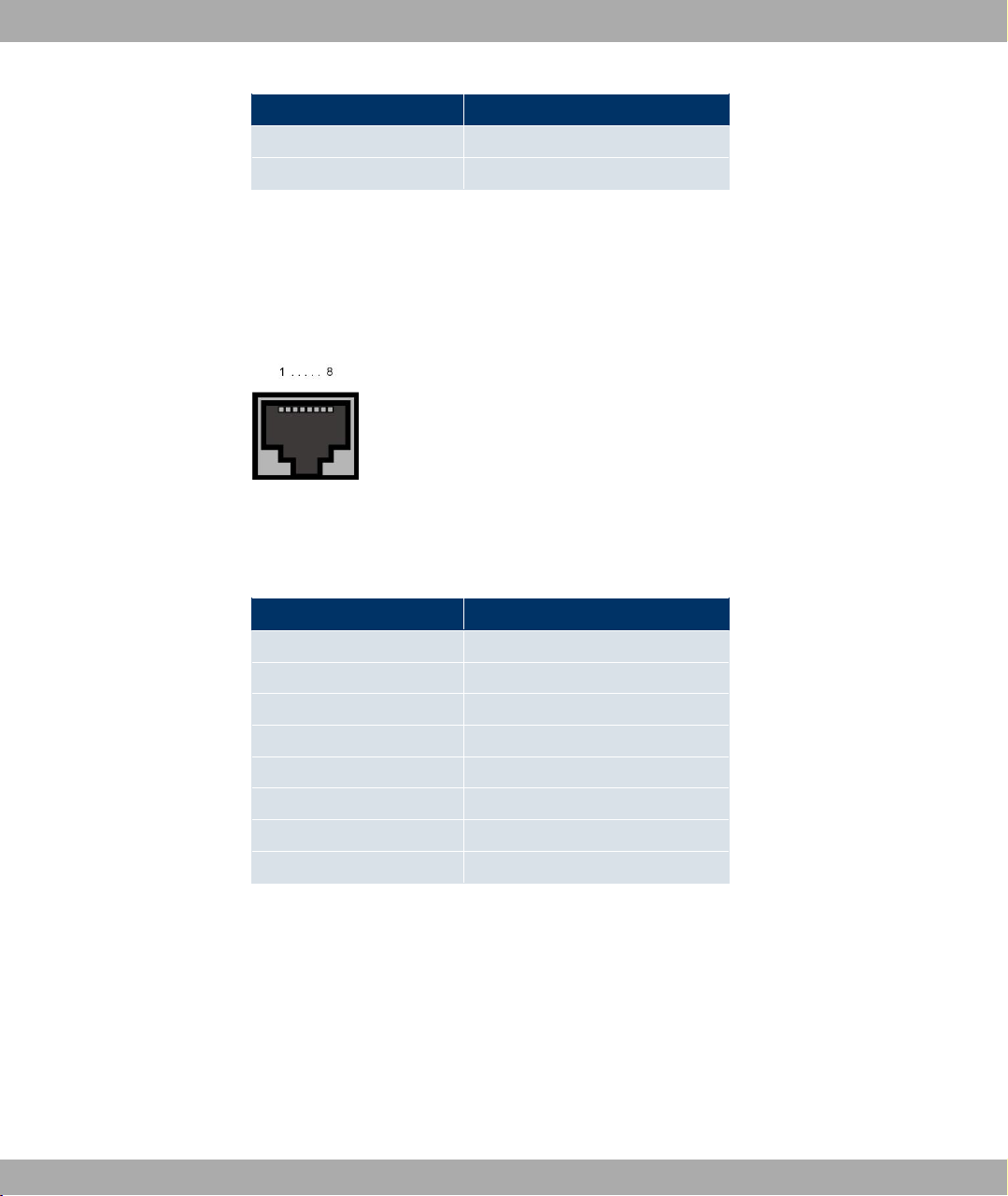
3 Technical data Funkwerk Enterprise Communications GmbH
Pin Function
3 b
4 Not used
3.4.5.4 ISDN S0 port
bintec R232bw has an additional ISDN-S0 interface, which can be used for back-up functions, for example.
The connection is made via an RJ45 socket.
Fig. 30: ISDN S0 BRI interface (RJ45 socket)
The pin assignment for the ISDN S0 BRI interface (RJ45 socket) is as follows:
RJ45 socket for ISDN connection
Pin Function
1 Not used
2 Not used
3 Transmit (+)
4 Receive (+)
5 Receive (-)
6 Transmit (-)
7 Not used
8 Not used
50 bintec R200 Series
Page 63

Funkwerk Enterprise Communications GmbH
Chapter 4 Access and Configuration
This chapter describes all the access and configuration options.
4.1 Access Options
The various access options are presented below. Select the procedure to suit your needs.
There are various ways you can access your device to configure it:
• Via your LAN
• Via the serial interface
• Via an ISDN connection (R232a, R232bR232b and R232bw only)
4.1.1 Access via LAN
4 Access and Configuration
Access via one of the Ethernet interfaces of your device allows you to to open the Express
Setup Wizard and Funkwerk Configuration Interface in a web browser for configuration
purposes and to access your device via Telnet or SSH.
4.1.1.1 HTTP/HTTPS
With a current web browser, you can use the HTML interfaces to configure your device.
Configuration with the Express Setup Wizard is particularly easy. An extended configura-
tion can be set up using the Funkwerk Configuration Interface. For this, enter the follow-
ing in your web browser's address field:
• Express Setup Wizard:
http://192.168.0.254/wizard
or
https://192.168.0.254/wizard
• Funkwerk Configuration Interface:
http://192.168.0.254
or
https://192.168.0.254
bintec R200 Series 51
Page 64

4 Access and Configuration Funkwerk Enterprise Communications GmbH
4.1.1.2 Telnet
Apart from configuration using a web browser, with a Telnet connection you can also access the SNMP shell and use other configuration options. These are described in Configur-
ation options on page 58.
You do not need any additional software on your PC to set up a Telnet connection to your
device: Telnet is available on all operating systems.
Proceed as follows:
Windows
(1) Click Run… in the Windows Start menu.
(2) Enter telnet <IP address of your device>.
(3) Click OK.
A window with the login prompt appears. You are now in the SNMP shell of your
device.
(4) Continue with Logging in for Configuration on page 57.
Unix
You can also set up a Telnet connection on UNIX and Linux without any problem:
(1) Enter telnet <IP address of your device> in a terminal.
A window with the login prompt appears. You are now in the SNMP shell of your
device.
(2) Continue with Logging in for Configuration on page 57.
4.1.1.3 SSH
In addition to the unencrypted and potentially viewable Telnet session, you can also connect to your device via an SSH connection. This is encrypted, so all the remote maintenance options can be carried out securely.
The following preconditions must be met in order to connect to the device via SSH:
• The encryption keys needed for the process must be available on the device.
• An SSH client must be installed on your PC.
Encryption keys
First of all, make sure that the keys for encrypting the connection are available on your
device:
52 bintec R200 Series
Page 65

Funkwerk Enterprise Communications GmbH
(1) Log in to one of the types already available on your device (e.g. via Telnet - for login
see Logging in on page 56).
(2) Enter update -i for the input prompt. You are now in the Flash Management shell.
(3) Call up a list of all the files saved on the device: ls -al.
If you see a display like the one below, the keys needed are already there and you can
connect to the device via SSH:
Flash-Sh > ls -al
Flags Version Length Date Name ...
Vr-xpbc-B 7.1.04 2994754 2004/09/02 14:11:48 box150_srel.ppc860
Vrw-pl--f 0.0 350 2004/09/07 10:44:14 sshd_host_rsa_key.pub
Vrw-pl--f 0.0 1011 2004/09/07 10:44:12 sshd_host_rsa_key
Vrw-pl--f 0.0.01 730 2004/09/07 10:42:17 sshd_host_dsa_key.pub
Vrw-pl--f 0.0.01 796 2004/09/07 10:42:16 sshd_host_dsa_key
4 Access and Configuration
Flash-Sh >
Note
The device generates a key pair for each of the algorithms (RSA and DSA), i.e. two
files must be stored in the flash for each algorithm (see example at above).
If no keys are available, you have to generate these first. Proceed as follows:
(1) Leave the Flash Management shell with exit.
(2) Call up the Setup tool (setup) and navigate to the Security -> SSH Daemon -> Cer-
tification Management menu.
(3) To have the keys generated by the device, mark one of the two entries with the cursor
and confirm with Enter. The device then generates the key and stores it in the
FlashROM.
(4) Make sure that both keys have been successfully generated. To do this, repeat the
procedure described above.
Login via SSH
Proceed as follows to log in on your device via SSH:
If you have made sure that all the keys needed are available on the device, you have to
check whether an SSH client is installed on your PC. Most UNIX and Linux distributions in-
bintec R200 Series 53
Page 66

4 Access and Configuration Funkwerk Enterprise Communications GmbH
stall a SSH client by default. Additional software, e.g. PuTTY, usually has to be installed on
a Windows PC.
Proceed as follows to log in on your device via SSH:
UNIX
(1) Enter ssh <IP address of the device> in a terminal.
The login prompt window appears. This is located in the SNMP shell of the device.
(2) Continue with Logging in on page 56.
Windows
(1) How an SSH connection is set up very much depends on the software used. Consult
the documentation for the program you are using.
As soon as you have connected to the device, the login prompt window will appear.
You are now in the SNMP shell of your gateway.
(2) Continue with Logging in on page 56.
Note
PuTTY requires certain settings for a connection to a bintec device. The support
pages of http://www.funkwerk-ec.com include FAQs, which list the required settings.
4.1.2 Access via the Serial Interface
Each bintec gateway has a serial interface, with which a PC can be connected directly.
The following chapter describes what you have to remember when setting up a serial connection and what you can do to configure your device in this way.
Access via the serial interface is ideal if you are setting up an initial configuration of your
device and a LAN access is not possible via the pre-configured IP address
(192.168.0.254/255.255.255.0).
Windows
To connect your device to your PC via the serial interface, proceed as described in Quick
Install Guide on page 8. The Quick Install Guide is included with your device in printed
form and is also on the Companion CD.
If you are using a Windows PC, you need a terminal program for the serial connection, e.g.
HyperTerminal. Make sure that HyperTerminal was also installed on the PC with the Windows installation. However, you can also use any other terminal program that can be set to
the corresponding parameters (see below).
54 bintec R200 Series
Page 67

Funkwerk Enterprise Communications GmbH
If you have installed the BRICKware as described in the Quick Install Guide, two links are
provided in the Windows Start menu. If you use these, you do not have to make any other
settings for the serial connection to your device.
Proceed as follows to access your device via the serial interface:
(1) In the Windows-start menu, click on Programs -> BRICKware-> Device on COM1
(or Device on COM2 , if you use the COM2 port of your PC) to start HyperTerminal.
(2) Press Return (at least once) after the HyperTerminal window opens.
A window with the login prompt appears. You are now in the SNMP shell of your device.
You can now log in on your device and start the configuration.
Check
If the login prompt does not appear after you press Return several times, the connection to
your device has not been set up successfully.
Therefore, check the COM1 or COM2 settings on your PC.
(1) Click on File -> Properties.
(2) Click Configure in the Connect to tab.
The following settings are necessary:
- Bits per second: 9600
- Data bits: 8
- Parity: None
- Stopbits: 1
- Flow control: None
(3) Enter the values and click OK.
(4) Make the following settings in the Settings tab:
- Emulation: VT100
(5) Click OK.
4 Access and Configuration
The changes to the terminal program settings do not take effect until you disconnect the
connection to your device and then make the connection again.
If you use HyperTerminal, there may be problems with displaying umlauts and other special
characters. If necessary, therefore, set HyperTerminal to Autodetection instead of VT
100.
Unix
You will require a terminal program such as cu (on System V), tip (on BSD) or minicom
(on Linux). The settings for these programs correspond to those listed above.
bintec R200 Series 55
Page 68

4 Access and Configuration Funkwerk Enterprise Communications GmbH
Example of a command line for using cu: cu -s 9600 -c/dev/ttyS1
Example of a command line for using tip: tip -9600 /dev/ttyS1
4.1.3 Access over ISDN
All devices that have an ISDN interface can be accessed and configured from another
device via an ISDN call.
Access over ISDN with ISDN Login is especially recommended if your device is to be remotely configured or maintained. This is also possible even if your device is still in the ex
works state. Access is then obtained with the aid of a device that is already configured or a
PC with an ISDN card in the remote LAN. The device to be configured in your own LAN is
reached via a number of the ISDN connection (e.g. 1234). This enables the administrator in
the Remote LAN to configure your device remotely, for example.
Note
If you connect an unconfigured device to an ISDN connection in parallel to a PBX, the
PBX cannot take any calls until an ISDN number is configured on the device.
Access over ISDN costs money. If your device and your computer are in the LAN, it is
cheaper to access your device via the LAN or via the serial interface.
Your device in your LAN merely needs to be connected to the ISDN connection and
switched on.
To reach your device over ISDN Login, proceed as follows:
(1) Connect your device to the ISDN.
(2) Log in as administrator on your device in the remote LAN in the usual way.
(3) In the SNMP shell, type in isdnlogin <number of the ISDN connection of
your device>, e.g. isdnlogin 1234.
(4) The login prompt appears. You are now in the SNMP shell of your device.
Continue with Logging in for Configuration on page 57.
4.2 Logging in
With certain access data, you can log in on your device and carry out different actions. The
extent of the actions available depend on the authorisations of the user concerned.
56 bintec R200 Series
Page 69

Funkwerk Enterprise Communications GmbH
A login prompt appears first, regardless of how you access your device. You cannot view
any information on the device or change the configuration without authentication.
4.2.1 User names and passwords in ex works state
In its ex works state, your device is provided with the following user names and passwords:
User names and passwords in ex works state
User name Password Authorisations
admin funkwerk Read and change system variables, save configuration; use Ex-
write public Read and write system variables (except passwords) (changes
read public Read system variables (except passwords).
It is only possible to change and save configurations if you log in with the user name admin. Access information (user names and passwords) can also only be changed if you log
in with the user name admin. For security reasons, passwords are normally shown on the
Setup Tool screen not in plain text, but only as asterisks. The user names, on the other
hand, are displayed as plain text.
4 Access and Configuration
press Setup Wizard, Funkwerk Configuration Interface and
Setup Tool.
are lost when you switch off your device).
The security concept of your device enables you to read all the other configuration settings
with the user name read, but not the access information. It is therefore impossible to log in
with read, read the password of the admin user and subsequently log in with admin and
make changes to the configuration.
Caution
All bintec devices are delivered with the same username and password. As long as
the password remains unchanged, they are not protected against unauthorised use.
How to change the passwords is described in Changing the Password on page 77.
Make sure you change the passwords to prevent unauthorised access to your device
If you have forgotten your password, you must reset your device to the ex works state,
which means your configuration will be lost.
4.2.2 Logging in for Configuration
Set up a connection to the device. The access options are described in Access Options on
page 51.
bintec R200 Series 57
Page 70

4 Access and Configuration Funkwerk Enterprise Communications GmbH
Funkwerk Configuration Interface
Log in via the HTML surface as follows:
(1) Enter your user name in the User field of the input window.
(2) Enter your password in the Password field of the input window and confirm with Re-
turn or click the Login button.
The status page of the Funkwerk Configuration Interface opens in the browser.
SNMP shell
Log into the SNMP shell as follows:
(1) Enter your user name e.g. admin, and confirm with Return.
(2) Enter your user password e.g. funkwerk, and confirm with Return.
Your device logs in with the input prompt, e.g. r232bw:>. The login was successful. You
are now in the SNMP shell.
To leave the SNMP shell after completing the configuration, enter exit and press Return.
4.3 Configuration options
This chapter first offers an overview of the various tools you can use for configuration of
your device.
You can configure your device in the following ways:
• Express Setup Wizard for beginners
• Funkwerk Configuration Interface for advanced users
• Setup Tool for experts
• SNMP shell commands
The configuration options available to you depend on the type of connection to your device:
Types of connections and configurations
Type of connection Possible types of configuration
LAN Express Setup Wizard, Funkwerk Configuration Interface,
ASCII Setup Tool, shell commands
Serial connection ASCII Setup Tool, shell commands
58 bintec R200 Series
Page 71

Funkwerk Enterprise Communications GmbH
Therefore, several types of configuration are available for each type of connection.
Note
To change the device configuration, you must log in with the user name admin. If you
do not know the password, you cannot make any configuration settings. This applies to
all types of configuration.
4.3.1 Express Setup Wizard for beginners
You have already learnt about configuration with the Express Setup Wizard in the Quick
Install Guide. It is used to perform the basic configuration of your device quickly and can
also be used if you can address the device with its preset IP configuration from your LAN.
This usually covers most standard configurations.
However, if you would like to make further settings, you can use the other configuration
methods mentioned above. You can first configure your device with the Express Setup
Wizard and subsequently extend or change this initial configuration with one of the other
tools. In many cases, configuration using the Express Setup Wizard alone will be sufficient.
4 Access and Configuration
The Express Setup Wizard guides you through the configuration. Once you have exited
the Express Setup Wizard, your device is ready for use. The information you need for
configuration with the Express Setup Wizard and the prerequisites for this can be found in
the Quick Install Guide on page 8, which is also available to you in printed form.
The detailed help system of the Express Setup Wizard will help you to clarify any ques-
tions you may have. As a result, a detailed description of the Express Setup Wizard is not
provided here.
4.3.2 Funkwerk Configuration Interface for advanced users
The Funkwerk Configuration Interface is a web-based graphic user surface that you can
use from any PC with an up-to-date web browser via an HTTP or HTTPS connection.
You can use the Funkwerk Configuration Interface to carry out all configuration tasks
easily. It is integrated in your device and is available in English. If required, other languages
can be downloaded from the download area of www.funkwerk-ec.com and installed on
your device. To do this, proceed as described in Options on page 354.
The settings you make with the Funkwerk Configuration Interface are applied with the
OK or Apply button of the menu, and you do not have to restart the device.
If you finish the configuration and want to save your settings so that they are loaded as the
bintec R200 Series 59
Page 72

4 Access and Configuration Funkwerk Enterprise Communications GmbH
boot configuration when you reboot your device, save these by clicking the Save configur-
ation button.
You can also use the Funkwerk Configuration Interface to monitor the most important
function parameters of your device.
Fig. 31: Funkwerk Configuration Interface Initial Screen
60 bintec R200 Series
Page 73

Funkwerk Enterprise Communications GmbH
4.3.2.1 Calling the Funkwerk Configuration Interface
(1) Check whether the device is connected and switched on and that all the necessary
cables are correctly connected (see Connections on page 10).
(2) Check the settings of the PC from which you want to configure your device (see Con-
figuring a PC on page 17).
(3) Open a web browser.
(4) Enter http://192.168.0.254 in the address field of the web browser.
(5) Enter admin in the User field and funkwerk in the Password field and click LOGIN.
You are not in the status menu of your device's Funkwerk Configuration Interface (see
Status on page 83).
4.3.2.2 Operating elements
Funkwerk Configuration Interface window
The Funkwerk Configuration Interface window is divided into three areas:
4 Access and Configuration
• The header
• The navigation bar
• The main configuration window
Fig. 32: Areas of the Funkwerk Configuration Interface
Header
bintec R200 Series 61
Page 74

4 Access and Configuration Funkwerk Enterprise Communications GmbH
Fig. 33: Funkwerk Configuration Interface header
Funkwerk Configuration Interface header
Menu Function
Language selection: From the dropdown menu, select the language in which the Funkwerk Configuration Interface is to be
displayed. Here, you can select the language in which you want
to carry out the configuration. German and English are available.
Online Help: Click this button if you want help with the menu
now active. The description of the sub-menu where you are now
is displayed.
Express Setup Wizard: Click this button if you want to activate
the configuration wizard. The configuration assistant is opened
in a new window and takes you step-by-step through the basic
configuration of your device and alternatively also through the
configuration of an Internet access, a wireless LAN connection
and a VPN connection.
Logout: If you want to end the configuration, click this button to
log out of your device. A window is opened offering you the following options:
• Continue with the configuration,
• Save the configuration and close the window,
• Exit the configuration without saving.
Navigation bar
Fig. 34: Save Configuration button
62 bintec R200 Series
Page 75
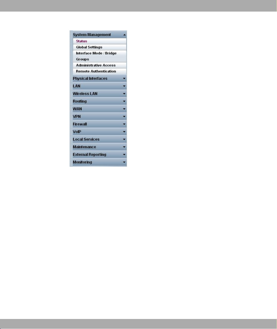
Funkwerk Enterprise Communications GmbH
4 Access and Configuration
Fig. 35: Menus
The Save Configuration button is found in the navigation bar. Click the Save Configuration button to save all configuration changes, so that they are loaded as the boot configura-
tion the next time you start the device.
The navigation bar also contains the main configuration menus and their sub-menus.
Click the main menu you require. The corresponding sub-menu then opens.
If you click the sub-menu you want, the entry selected will be displayed in red. All the other
sub-menus will be closed. You can see at a glance the sub-menu you are in.
Status page
If you call the Funkwerk Configuration Interface, after you log in the status page of your
device is displayed. The most important data of your device can be seen on this at a
glance.
Main configuration window
The sub-menus generally contain several pages. These are called using the buttons at the
top of the main window. If you click a button, the window is opened with the basic paramet-
bintec R200 Series 63
Page 76

4 Access and Configuration Funkwerk Enterprise Communications GmbH
ers. You can extend this by clicking the Advanced Settings tab, which displays the additional options.
Configuration elements
The various actions that you can perform when configuring your device in the Funkwerk
Configuration are triggered by means of the following buttons:
Funkwerk Configuration Interface buttons
Button Function
Updates the view.
If you do not want to save a newly configured list entry, cancel
this and any settings made by pressing Cancel.
Confirms the settings of a new entry and the parameter
changes in a list.
Immediately starts the configured action.
Calls the the sub-menu to create a new entry.
Inserts an entry in an internal list.
Funkwerk Configuration Interface buttons for special functions
Button Function
In the Access Point Search menu, you use this button to start
automatic detection of all the access points available and connected by Ethernet in the network.
In the VPN -> Certificates -> Certificates and the VPN -> Cer-
tificates -> CRLs menus, this button opens the sub-menus for
configuring the certificates or CRL imports.
In the VPN -> Certificates -> Certificates menu, this button
opens the sub-menu for the configuration of the certificate request.
In the Surveillance -> ISDN/Modem -> Current calls menu,
clicking on this button ends the active calls selected in the
column.
Various icons indicate the following possible actions or statuses:
Funkwerk Configuration Interface icons
64 bintec R200 Series
Page 77

Funkwerk Enterprise Communications GmbH
Icon Function
4 Access and Configuration
Deletes the list entry.
Displays the menu for changing the settings of an entry.
Displays the details for an entry.
Moves an entry. A combo box opens in which you can choose
the list entry that selected entry is to be be placed in front of/
after.
Creates another list entry first and opens the configuration
menu.
Sets the status of the entry to Inactive .
Sets the status of the entry to Active.
Indicates "Dormant" status for an interface or connection.
Indicates "Up" status for an interface or connection.
Indicates "Down" status for an interface or connection.
Indicates "Blocked" status for an interface or connection.
Indicates "Going up" status for an interface or connection.
Indicates that data traffic is encrypted.
Triggers a WLAN bandscan.
Displays the next page in a list.
Displays the previous page in a list.
You can select the following operating functions in the list view:
Funkwerk Configuration Interface list options
Menu Function
Update Interval Here you can set the interval in which the view is to be updated.
To do this, enter a period in seconds in the input field and confirm it with .
Filter You can have the list entries filtered and displayed according to
bintec R200 Series 65
Page 78

4 Access and Configuration Funkwerk Enterprise Communications GmbH
Menu Function
certain criteria.
You can determine the number of entries displayed per page by
entering the required number in View x per Page.
Use the and buttons to scroll one page forward and one
page back.
You can filter according to certain keywords within the configuration parameters by selecting the filter rule you want under Fil-
ter in x <Option> y and entering the search word in the input
field. starts the filter operation.
Configuration elements Some lists contain configuration elements.
You can therefore change the configuration of the corresponding list entry directly in the list.
Fig. 36: Configuration of the des update interval
Fig. 37: Filter list
Structure of the Funkwerk Configuration Interface configuration menus
The menus of the Funkwerk Configuration Interface contain the following basic struc-
tures:
Funkwerk Configuration Interface menu structure
Menu Function
Basic configuration
menu/list
Sub-menu The New button is available in each menu in which a list of all
When you select a menu from the navigation bar, the menu of
basic parameters is displayed first. In a sub-menu containing
several pages, the menu containing the basic parameters is displayed on the first page.
The menu contains either a list of all the configured entries or
the basic settings for the function concerned.
the configured entries is displayed. Click the button to display
the configuration menu for creating a new list entry.
66 bintec R200 Series
Page 79

Funkwerk Enterprise Communications GmbH
Menu Function
Sub-menu Click this button to process the existing list entry. You go to the
Menu Click this tab to display extended configuration options.
The following options are available for the configuration:
Funkwerk Configuration Interface configuration elements
Menu Function
Input fields e.g. empty text field
Radio buttons e.g.
4 Access and Configuration
configuration menu.
Text field with hidden input
Enter the data.
Select the corresponding option.
Checkboxes e.g. activation by selecting checkbox
Selection of several possible options
Dropdown menus e.g.
Click the arrow to open the list. Select the required option using
the mouse.
Internal lists e.g.
Click . A new list entry is created. Enter the corresponding data. If list input fields remain empty, these are not saved
bintec R200 Series 67
Page 80

4 Access and Configuration Funkwerk Enterprise Communications GmbH
Menu Function
when you confirm with OK. Delete the entries by clicking the
icon.
Display of options that are not available
Options that are not available because they depend on the selection of other options are
generally hidden. If the display of these options could be helpful for a configuration decision, they are instead greyed out and cannot be selected.
Important
Please look at the messages displayed in the sub-menus. These provide information
on any incorrect configurations.
Warning symbols
Symbol Meaning
This symbol appears in messages referring you to settings
that were made with the Setup Tool.
This symbol appears in messages referring you to the fact
that values were entered or selected incorrectly.
Pay particular attention to the following message:
"Warning: changes not supported by the Setup Tool!". If you makes these changes
with the Funkwerk Configuration Interface, this can cause inconsistencies or mal-
functions. Therefore, it is recommended that the configuration is continued with the
Setup Tool.
4.3.2.3 Funkwerk Configuration Interface menus
The configuration options of your device are contained in the sub-menus, which are displayed in the navigation bar in the left-hand part of the window.
Note
Please note that not all devices have the full range of functions. Check the software of
your device on the corresponding product page under www.funkwerk-ec.com.
The Funkwerk Configuration Interface contains the following menus:
68 bintec R200 Series
Page 81

Funkwerk Enterprise Communications GmbH
System Management
Menu Function
Status In this menu, general information on your device is displayed at
Global Settings In this menu, you enter the basic system settings of your device,
4 Access and Configuration
a glance.
This information includes serial number, software version, current memory and processor use, status of the physical interfaces and the last 10 system messages.
such as, for example, system name, system date, system time
and passwords.
You can also manage licences that are necessary for the use of
certain functions.
Interface Mode / Bridge
Groups
Administrative Access In this menu, you configure the access options for the individual
Remote Authentication In this menu, you configure the authentication via a RADIUS
Physical Interfaces
Menu Function
Ethernet Ports In this menu, you configure the Ethernet interfaces of your
ISDN Ports In this menu, you configure the ISDN interface of your device.
ADSL Modem In this menu, you make the basic settings for your ADSL con-
In this menu, you define the mode in which the interfaces of
your device are to run (routing or bridging) and if necessary can
define bridge groups.
interfaces.
server or TACAS+ server.
device. To do this, you select the speed and type of interface,
for example.
Here you enter data such as the type of ISDN connection to
which your device is connected.
nection.
LAN
bintec R200 Series 69
Page 82

4 Access and Configuration Funkwerk Enterprise Communications GmbH
Menu Function
IP Configuration In this menu, you carry out the IP configuration of the LAN inter-
faces for your device.
VLAN In this menu, you configure the VLANs.
Wireless LAN
Menu Function
WLAN1 In this menu, you configure your wireless modules as an access
point or bridge.
Administration In this menu, you make the basic WLAN settings.
Routing
Menu Function
Routes In this menu, you enter additional routes.
NAT In this menu, you configure the NAT firewall (NAT, Network Ad-
dress Translation).
RIP In this menu, you configure the dynamic updating of the routing
table via RIP.
Load Balancing In this menu, you configure application-controlled bandwidth
management.
Multicast In this menu, you configure the use of multimedia streaming
protocols for e.g. voice over IP or video and audio streaming
(e.g. IPTV or Webradio) or TriplePlay (voice, video, data).
WAN
Menu Function
Internet + Dialup In this menu, you define the Internet connections for the various
connection protocols or dialup connections.
ATM In this menu, you carry out configuration of the ATM profiles that
are needed for all the ADSL connections and also connection
monitoring (OAM) and ATM QoS.
Real Time Jitter Con- In this menu, you can optimise the low-bandwidth transmission
70 bintec R200 Series
Page 83

Funkwerk Enterprise Communications GmbH
Menu Function
trol of voice data packets.
VPN
Menu Function
IPSec In this menu, you configure VPN connections over IPSec.
L2TP In this menu you configure the use of L2TP (Layer 2 Tunnelling
PPTP In this menu, you configure the an encrypted PPTP tunnel.
GRE This menu shows a list of all configured GRE tunnels.
Certificates In this menu you can generate and import keys and have them
Firewall
Menu Function
4 Access and Configuration
Protocol).
certified.
Policies In this menu you configure the filter rules for the firewall.
Interfaces In this menu, you can group together the interfaces to be
filtered.
Addresses In this menu, you can create the address aliases to be filtered.
Services In this menu, you can create the service aliases to be filtered.
VoIP
Menu Function
SIP In this menu, you configure a network transition between vari-
ous telecommunication networks.
RTSP In this menu, you configure the use of the RealTime Streaming
protocol.
Local Services
Menu Function
DNS In this menu, you configure the name resolution.
bintec R200 Series 71
Page 84

4 Access and Configuration Funkwerk Enterprise Communications GmbH
Menu Function
DynDNS Client In this menu, you configure the dynamic name resolution.
DHCP Server In this menu, you configure your device as a DHCP server.
Web Filter In this menu, you configure the use of the URL-based Proventia
Web Filter from ISS (www.iss.net).
CAPI Server In this menu, you configure your device as a CAPI server.
Scheduling In this menu, you configure time-dependent standard actions of
your devices.
Surveillance In this menu, you configure the surveillance of interfaces or
hosts in the network.
ISDN theft protection In this menu you can configure the ISDN theft protection func-
tion for each interface.
Funkwerk Discovery In this menu, you can configure management functions for
bintec Access Point.
UPnP In this menu, you configure the UPnP settings individually for
each interface of your gateway.
Maintenance
Menu Function
Diagnostics In this menu you can test the accessibility of hosts, DNS servers
or routing.
Software & Configuration
Reboot In this menu, you can initiate the rebooting of the device.
External Reporting
Menu Function
Syslog In this menu, you configure the host to which the data logged in-
In this menu, you manage your device's software version, configuration files and interface language.
ternally on the device is forwarded for saving and further processing.
IP Accounting In this menu, you decide for which interfaces accounting mes-
72 bintec R200 Series
Page 85

Funkwerk Enterprise Communications GmbH
Menu Function
E-mail alert Depending on the configuration, in this menu e-mails are sent to
SNMP In this menu, you configure whether the device is to listen for
Activity Monitor In this menu, you configure the surveillance of your device with
Monitoring
Menu Function
Internal Log In this menu, the system messages are displayed.
IPSec In this menu, the IPSec connections and connection statistics
4 Access and Configuration
sages are to be generated.
the administrator as soon as relevant syslog messages occur.
external SNMP accesses and send SNMP traps.
the Windows Tool Activity Monitor (component of BRICKware
for Windows).
that are currently active are displayed.
ISDN/Modem In this menu, the ISDN connections are displayed.
Interfaces In this menu, connection statistics and status of all interfaces
are displayed.
WLAN This menu shows you the WLAN connections statistics.
4.3.3 The Setup Tool for experts
The Setup Tool is a menu-controlled ASCII tool for the configuration and administration of
your device and, in addition to the SNMP commands, also allows access to all the configuration parameters.
To start the Setup Tool, you can be connected to the device in any way you like: It does not
matter whether you connect to the device via the LAN or via a serial connection.
Proceed as follows to start a Setup Tool session:
(1) Log in to your device as admin (see Logging in for Configuration on page 57).
(2) Enter setup after the input prompt and press Return.
The main menu of the ASCII Setup Tool opens.
bintec R200 Series 73
Page 86

4 Access and Configuration Funkwerk Enterprise Communications GmbH
Setup Tool menu
The main menu may differ from device to device, depending on the configuration level of
your device. Every Setup Tool menu contains three areas:
• The menu line contains a navigation aid to show you where you currently are in the
Setup Tools menu system. The system name of your device is also displayed. This is especially helpful if you are using several bintec devices with different system names.
• The configuration window is where the actual entries are made and the respective settings displayed. The field in which the cursor is currently located is shown with inverted
colours.
• The help line tells you how to move around in the current menu, which entries you can
change or which values are possible for an entry.
Basically, a menu looks like this:
Fig. 38: Setup Tool menu
4.3.3.1 Menu Navigation
You can use the following keys or key combinations to move about in the Setup Tool:
Navigation in the Setup Tool
Key combination Meaning
Tabulator Jump to the next field in the menu.
Return key Open sub-menu or activate command (e.g. SAVE).
up or down (arrow keys) Go to the next or previous field in the menu (works with VT 100
emulation when using a terminal program).
left or right (arrow keys) Show next and previous values of fields (works with VT 100
emulation when using a terminal program).
74 bintec R200 Series
Page 87

Funkwerk Enterprise Communications GmbH
Key combination Meaning
EscEsc Esc twice in succession: Return to the previous menu. Changes
Space bar Select list entries to be deleted. The selected entries are
Ctrl - l Update display.
Ctrl - n Jump to the next field in the menu.
Ctrl - p Jump to the previous field in the menu.
Ctrl - f Scroll down in a list that cannot be displayed in full. A "-" sign at
Ctrl - b Scroll up in a list that cannot be displayed in full. A "-" sign at
Ctrl - c Exit Setup Tool.
4 Access and Configuration
are lost.
marked with D. Pressing Space again removes the selection.
Select possible values of a variable (same as arrow keys).
the bottom right indicates the end of the list and a "v" indicates
more to come.
the top right indicates the start of the list and a " ^ " indicates
more to come.
4.3.3.2 Menu Commands
When you start moving around in the Setup Tool, you will notice that some menus have
special command options, such as DELETE, SAVE and CANCEL. The meaning of the
commands is explained below:
Buttons in the Setup Tool
Button Meaning
ADD / APPEND Add a new item to a list. A sub-menu opens for entering the de-
sired settings.
CANCEL Delete all changes in the menu just displayed.
DELETE Delete all entries selected with the Space bar for deletion from
a list. These changes become effective immediately.
OK Confirm the changes in the current menu. These changes be-
come effective when SAVE is pressed in the next menu.
SAVE Save all the entries of the current menu and all the sub-menus
in the working memory. These changes become effective immediately.
EXIT Leave the current menu and return to the main menu. Any
entries made are lost.
bintec R200 Series 75
Page 88

4 Access and Configuration Funkwerk Enterprise Communications GmbH
Note
To save the configuration to the flash memory, you must leave the Setup Tool with
Save as boot configuration and exit.
4.3.3.3 Searching Lists
Some Setup Tool menus contain lists of several entries, e.g. the WAN Partner menu,
which lists all WAN partners:
Fig. 39: Setup Tool search
These lists are arranged in alphabetical order according to the contents of the first field. An
incremental search function is provided, which is very useful for searching for an item in
very long lists.
Proceed as follows:
(1) Enter the first letter of the entry you are looking for, with the cursor located on a list
entry. Entries can be made in upper or lower case.
(2) If necessary, enter more characters to refine the search.
(3) The Backspace or Delete key can be used to edit the search string.
The cursor automatically jumps to the first match it finds with the corresponding initial letters. The characters entered for the search are displayed in the help line at the bottom of
the menu.
Do not enter invisible characters, such as Tabulator or Space as they stop the search and
could cause a function to be executed.
76 bintec R200 Series
Page 89

Funkwerk Enterprise Communications GmbH
Note
Make sure the cursor is positioned in a list element. The search cannot run if the cursor is located in a command field, e.g. ADD or DELETE.
In the WAN Partner menu shown above, the entries provide the following search results:
Search results
Input Cursor jumps to entry
p or P Partner1
pr, Pr, pR, PR PROVIDER
partner2 Partner1, on entering 2 to Partner2
4.3.3.4 Changing the Password
The procedure described below for changing the password applies to all passwords on
your device: the access passwords for the user names admin, read and write, the HTTP
password, the PPP password and the provider password.
4 Access and Configuration
Any character may be used for entering a password. Passwords are only displayed as asterisks, even while changes are being made. The number of asterisks is the same as the
number of characters in the password.
Note
To start the Setup Tool of your device in a mode in which the passwords are displayed
in plain text and can be changed by one-time editing, you must enter the command
setup -p. This option only exists if you have logged in on your device with the user
name admin. In the password field, the Backspace key always deletes the complete
entry, not just one character.
Proceed as follows:
(1) Select the password field in the desired menu and enter the new password.
(2) The field changes to the change mode and the message Change Password appears
in the help line.
(3) Now press Return, Tabulator or a Cursor key to confirm. The field changes to the
confirm mode and Confirm Password is displayed in the help line.
(4) Now enter the new password again and confirm by pressing Return, Tabulator or a
Cursor key. If you have entered the repeat password correctly, the password is
changed. The new password is saved on leaving the menu with the SAVE button. If
bintec R200 Series 77
Page 90

4 Access and Configuration Funkwerk Enterprise Communications GmbH
you leave the menu by pressing CANCEL or Esc Esc, the password change is not
saved. If the two entries were not the same, the field is reset to the old password and
the help line shows the following message: "Password doesn't match. Try
again."
4.3.3.5 Menu structure
The main menu of the Setup Tool looks like this:
Fig. 40: Setup Tool main menu
The menu structure (main menu and first sub-menu) of the Setup Tool looks like this:
78 bintec R200 Series
Page 91

Funkwerk Enterprise Communications GmbH
4 Access and Configuration
Fig. 41: Setup Tool menu structure
To help you when making the configuration settings, the menus are briefly explained below:
Setup Tool menus
Menu Function
Licences In this menu, you can manage licences that are needed for us-
ing certain functions.
System In this menu, you enter the basic system settings of your device,
such as, for example, system name, system date, system time,
passwords.
External Systems In this menu, you can configure management functions for ex-
ternal systems, e.g. bintec access points.
LAN In this menu, you can configure the 4-port Ethernet switch
(LAN) of your device. The switch ports can be configured independently of each other.
bintec R200 Series 79
Page 92

4 Access and Configuration Funkwerk Enterprise Communications GmbH
Menu Function
ETH In this menu, you configure the Ethernet interface of your
device. Here you enter data such as the IP address and network mask of the device, for example.
ISDN In this menu, you configure the ISDN interface of your device.
Here you enter data such as the type of ISDN connection to
which your device is connected. The sub-menu ISDN S0 -> In-
coming Call Answering is for assigning the available ISDN
numbers to the desired services (e.g. PPP routing, ISDN Login).
WLAN In this menu, you configure the connection to a host in the LAN
over WLAN.
xDSL In this menu, you make the basic settings for your ADSL con-
nection.
WAN Partner In this menu, you define all the WAN partners e.g. your Internet
Service Provider (ISP). All the WAN partners entered are displayed in a list that includes the name of partner, protocol used
and current status.
Security In this menu, you configure the security functions of your
device, e.g. Stateful Inspection Firewall and Web Filtering.
IPSEC In this menu, you configure VPN connections over IPSec.
IP In this menu, you enter all the settings that concern the IP pro-
tocol.
PPP This menu contains universal PPP settings, e.g. "Authentication
Protocol", which do not just relate to individual WAN partners.
CREDITS In this menu, you manage your device's Credits Based Account-
ing System.
CAPI In this menu, you make the settings for the bintec CAPI User
Concept.
ATM In this menu, you carry out configuration of the ATM profiles that
are needed for all the ADSL connections and also connection
monitoring (OAM) and ATM QoS.
QoS In this menu, you configure all the "Quality of Service" settings.
VoIP
L2TP
VLAN In this menu, you configure the VLANs.
Configuration Manage- In this menu, you can manage your device's configuration files.
In this menu you configure the voice over IP functions (VoIP) of
your device.
In this menu, you configure the use of the RealTime Streaming
protocol.
80 bintec R200 Series
Page 93

Funkwerk Enterprise Communications GmbH
Menu Function
ment You can save them either locally on your device or on your
Monitoring and Debugging
Exit You use Exit to leave the Setup Tool. You save the configura-
4.3.4 SNMP shell
SNMP (Simple Network Management Protocol) is a protocol that defines how you can access the configuration settings.
All configuration settings are stored in the MIB (Management Information Base) in the form
of MIB tables and MIB variables. You can access these directly from the SNMP shell via
SNMP commands. This type of configuration requires a detailed knowledge of our devices.
4 Access and Configuration
computer, for example.
This menu includes sub-menus that enable you to locate problems in your network and monitor activities, e.g. at your device's
WAN interface.
tion file in the flash memory with Exit-> Save as boot configur-
ation and exit. This file is loaded when you reboot your device.
Leave the Setup Tool without saving the configuration in the
flash memory with Exit -> Exit without saving.
4.4 BOOTmonitor
The BOOTmonitor is only available over a serial connection to the device.
The BOOTmonitor provides the following functions, which you select by entering the corresponding number:
(1) Boot System (reboot the system):
The device loads the compressed boot file from the flash memory to the working
memory. This happens automatically on starting.
(2) Software Update via TFTP:
The devices performs a software update via a TFTP server.
(3) Software Update via XMODEM:
The device performs a software update via a serial interface with XMODEM.
(4) Delete configuration:
The device is reset to the ex works state. All configuration files are deleted and the
BOOTmonitor settings are set to the default values.
(5) Default BOOTmonitor Parameters:
You can change the default settings of the BOOTmonitor of the device, e.g. the
baud rate for serial connections.
bintec R200 Series 81
Page 94

4 Access and Configuration Funkwerk Enterprise Communications GmbH
(6) Show System Information:
Shows useful information about your device, e.g. serial number, MAC address and
software versions.
The BOOTmonitor is started as follows.
The devices passes through various functional states when starting:
• Start mode
• BOOTmonitor mode
• Normal mode
After some self-tests have been successfully carried out in the start mode, your device
reaches the BOOTmonitor mode. The BOOTmonitor prompt is displayed if you are serially
connected to your device.
After display of the BOOTmonitor prompt, press the space bar within four seconds to use
the functions of the BOOTmonitor. If you do not make an entry within four seconds, the
device changes back to normal operating mode.
Note
If you change the baud rate (the preset value is 9600 baud), make sure the terminal
program used also uses this baud rate. If this is not the case, you will not be able to
establish a serial connection to the device.
82 bintec R200 Series
Page 95

Funkwerk Enterprise Communications GmbH
Chapter 5 System Management
The System Management menu contains general system information and settings.
You see a system status overview. Global system parameters such as the system name,
date/time, passwords and licences are managed and the access and authentication methods are configured.
5.1 Status
If you log into the Funkwerk Configuration Interface, your device's status page is dis-
played, which shows the most important system information.
You see an overview of the following data:
• System status
• Your device's activities: Resource utilisation, active sessions and tunnels
• Status and basic configuration of the LAN, WAN, ISDN, WLAN, and ADSL interfaces
• The last 10 system messages
5 System Management
You can customise the update interval of the status page by entering the desired period in
seconds as Automatic Update Interval and clicking on the Apply-button.
Caution
Under Automatic Refresh Interval do not enter a value of less than 5 seconds, other-
wise the refresh interval of the screen will be too short to make further changes!
bintec R200 Series 83
Page 96

5 System Management Funkwerk Enterprise Communications GmbH
Fig. 43: System Administration ->Status
The System Administration -> Status menu consists of the following fields:
Fields in the Status System Information menu
Field Value
Uptime Displays the time past since the device was rebooted.
System Date Displays the current system date and system time.
Serial Number Displays the device serial number.
BOSS Version Displays the currently loaded version of the system software.
Fields in the Status Resource Information menu
Field Value
CPU Usage Displays the CPU usage as a percentage.
84 bintec R200 Series
Page 97

Funkwerk Enterprise Communications GmbH
Field Value
Memory Usage Displays the usage of the working memory in MByte in relation
ISDN Usage External Displays the current number of ISDN B channels used in rela-
Active Sessions (SIF,
RTP, etc... )
Active IPSec Tunnels Displays the number of currently active IPSec tunnels in relation
Other fields in the menu Status
Field Value
5 System Management
to the available total working memory in MByte. The usage is
also displayed in brackets as a percentage.
tion to the total number of ISDN B channels available.
Displays the total of all SIF, TDRC, and IP load balancing sessions.
to the number of configured IPSec tunnels.
Physical Interface - Interface Specifics - Link
Recent System Logs Displays the last 10 system messages.
The physical interfaces are listed here and there most important
settings are shown. The system also displays whether the interface is connected or active.
Interface specifics for Ethernet interfaces:
• IP Address
• Netmask
Interface specifics for ISDN interfaces:
• Configured
• Not configured
Interface specifics for xDSL interfaces:
• Downstream/Upstream Line Speed
Interface Specifics for WLAN Interfaces:
Access Point Mode:
• Operation Mode: Access Point or Off
• The channel used on this wireless module
• Number of connected clients
• Number of WDS links
• Software version of the wireless card
bintec R200 Series 85
Page 98

5 System Management Funkwerk Enterprise Communications GmbH
5.2 Global Settings
The basic system parameters are managed in the Global Settings menu.
5.2.1 System
The System Administration -> Global Settings -> System menu is used for entering the
basic system data of your device.
Fig. 44: System Administration -> Global Settings-> System
The System Management -> Global Settings-> System menu consists of the following
fields:
Fields in the System Basic Parameters menu
Field Value
System Name Enter the system name of your device. This is also used as the
PPP host name.
A character string of up to 255 characters is possible.
The device type is entered as the default value.
Location Enter the location of your device.
86 bintec R200 Series
Page 99

Funkwerk Enterprise Communications GmbH
Field Value
Contact Enter the relevant contact person. Here you can enter the e-
5 System Management
mail address of the system administrator, for example.
A character string of up to 255 characters is possible.
The default value is BINTEC.
Maximum Number of
Syslog Entries
Maximum Message
Level of Syslog Entries
Enter the maximum number of syslog messages that are stored
internally in the device.
Possible values are 0 to 1000.
The default value is 50. You can view the stored messages in
Monitoring -> Internal Log.
Select the priority of system messages above which a log
should be created.
System messages are only recorded internally if they have a
higher or identical priority to that indicated, i.e. all messages
generated are recorded at syslog level debug.
Possible values:
• Emergency: Only messages with emergency priority are re-
corded.
• Alert: Messages with emergency and alert priority are recor-
ded.
• Critical: Messages with emergency, alert and critical prior-
ity are recorded.
• Errors: Messages with emergency, alert, critical and error
priority are recorded.
• Warning: Messages with emergency, alert, critical, error and
warning priority are recorded.
• Notice: Messages with emergency, alert, critical, error,
warning and notice priority are recorded.
• Information (default value) Messages with emergency,
alert, critical, error, warning, notice and information priority are
recorded.
• Debug: All messages are recorded.
bintec R200 Series 87
Page 100

5 System Management Funkwerk Enterprise Communications GmbH
Field Value
Maximum Number of Accounting Log Entries
Enter the maximum number of accounting entries that are
stored internally in the device.
Possible values are 0 to 1000.
The default value is 20.
5.2.2 Passwords
Setting the passwords is another basic system setting.
Fig. 45: System Administration -> Global Settings-> Passwords
Note
All bintec devices are delivered with the same username and password. As long as
the password remains unchanged, they are not protected against unauthorised use.
Make sure you change the passwords to prevent unauthorised access to the device
If the password is not changed, under System Administration-> Status appears the
warning: "System password not changed!"
The System Management -> Global Settings-> Passwords menu consists of the follow-
88 bintec R200 Series
 Loading...