

Page 1

TETRA Radio Set
Funkwerk
FT
4 (S)
Operating
Manual
Page 2

2
Manufacturer:
Funkwerk Security Communications GmbH
John-F.-Kennedy-Str. 43-53
D-38228 Salzgitter
www.funkwerk-sc.com
info@funkwerk-sc.com
Notes:
© Copyright 2013 by Funkwerk Security Communications GmbH.
All rights reserved.
All product names are trademarks of the respective owners.
No part of this Operating Manual may be reproduced or copied in any form (printing,
photocopying or other processes) without the written approval by Funkwerk Security
Communications GmbH.
We reserve the right to modify this Operating Manual at any time and without prior
announcement. Delivered Operating Manuals are not subject to a revision service by
us and will not be updated when modifications are implemented.
Errors and misprints excepted.
Product management · V 1.2 · 2012-04-20
Order No. 5010930002-a
Technical changes and availability reserved.
Page 3

Table of contents 3
Table of contents
Instructions for use
...................................................................................................
7
Features and type designation
....................................................................................
7
Technical terms and abbreviations
.............................................................................
9
Symbols and special fonts
........................................................................................
12
Safety
information ...................................................................................................
13
Intended use
.............................................................................................................
13
Duties of the system operator
...................................................................................
13
Radio network/Reachability
.......................................................................................
14
Information on use
....................................................................................................
15
Instructions for personal emergency signal units ...................................................... 15
Antennas used for TETRA radio
sets ........................................................................
16
Frequencies used
......................................................................................................
17
TETRA radio communications
..............................................................................
17
IOS localisation signals
........................................................................................
17
GPS-Localisation services
....................................................................................
17
Emission of radio signals
..........................................................................................
17
Risk of hearing damage
............................................................................................
18
Effects on electronic body aids
.................................................................................
18
Malfunctions of other units caused by the radio set .................................................. 19
Repair and maintenance
...........................................................................................
19
Storage
......................................................................................................................
20
Disposal
....................................................................................................................
20
Battery .......................................................................................................................
21
Charger
.....................................................................................................................
22
Conformity and approvals
......................................................................................
23
EC declaration of conformity
.....................................................................................
23
Page 4

4 Table of contents
Structure and
function
............................................................................................
27
Scope of supply
.........................................................................................................
27
Control elements
.......................................................................................................
28
Connections
..............................................................................................................
34
Signal tones
...............................................................................................................
37
Illuminated indicators
.................................................................................................
38
Left signal LED
......................................................................................................
38
Right signal LED
...................................................................................................
39
Display
.......................................................................................................................
40
Header line
............................................................................................................
40
F
ooter
....................................................................................................................
42
Idle display
............................................................................................................
43
Screen saver
.........................................................................................................
44
Menu
.....................................................................................................................
45
First steps
................................................................................................................
51
Programming
.............................................................................................................
51
Putting the radio set into operation
............................................................................
51
Charging the battery
..................................................................................................
54
Charging the battery with a FT4 Desktop Charger II / FT4 Desktop
Stat
ion ......... 54
Charging the battery with a FT4 Travel Charger
...................................................
58
Signalling the charging status
...............................................................................
59
TETRA basics
..........................................................................................................
61
Safety information
.....................................................................................................
61
TETRA connection
typ
es
...........................................................................................
61
Trunking mode (
TMO) ...........................................................................................
62
Direct mode (DMO)
...............................................................................................
64
Operation
.................................................................................................................
67
Switching on the radio set
.........................................................................................
67
Switching off the radio set
.........................................................................................
68
Menu
.........................................................................................................................
69
Navigating the menu
.............................................................................................
69
Changing back to the previous menu
...................................................................
72
Group calls
................................................................................................................
73
Selecting a group
..................................................................................................
73
Starting a group call
..............................................................................................
76
Receiving a group call
...........................................................................................
78
Answering a group call
..........................................................................................
79
Scanner function
...................................................................................................
81
Leaving a group call early
.....................................................................................
84
Page 5

Table of contents 5
Individual calls
...........................................................................................................
84
Duplex mode
........................................................................................................
85
Two-way call (direct through)
...............................................................................
88
TETRA Emergency Calls
..........................................................................................
90
Special features
....................................................................................................
90
Triggering a TETRA emergency call
....................................................................
91
Terminating a TETRA emergency call
..................................................................
92
Messaging
.................................................................................................................
93
Message types
.....................................................................................................
93
Composing an SDS text message
........................................................................
94
Composing an SDS text message from a template .............................................. 96
Transmitting an SDS text message
....................................................................
100
Transmitting a status message
...........................................................................
102
Setting the volume
..................................................................................................
103
Key lock
...................................................................................................................
105
Locking the keys
.................................................................................................
105
Unlocking the keys
.............................................................................................
106
Open listening mode ON/OFF during a call
............................................................
106
Muting the microphone during a call
.......................................................................
107
Brief instructions for selected functions
...................................................................
107
Personal emergency signal functions
................................................................
113
Will-dependent emergency signal fu
nct
ions
............................................................
113
Control elements
................................................................................................
113
Alarm types
.........................................................................................................
114
Time sequence
...................................................................................................
115
Will-independent emergency signal functions
.........................................................
116
Alarm types
.........................................................................................................
116
Triggering the loss alarm
....................................................................................
116
Pre-alarm
............................................................................................................
117
Time sequence
...................................................................................................
118
Localisation functions
..............................................................................................
120
Localisation of the radio set in case of alarm ..................................................... 120
Tracking of the radio set in an alarm situation .................................................... 120
Warden control mode
.........................................................................................
121
Technical alarms and faults
....................................................................................
121
Technical alarms
................................................................................................
121
Technical faults
...................................................................................................
122
Programming
...........................................................................................................
122
Page 6

6 Table of contents
Putting into operation
..............................................................................................
122
Quick reference guide
.........................................................................................
122
Perform a visual inspection
.................................................................................
123
Logging into the personal emergency signal centre
...........................................
124
Sensor
test ..........................................................................................................
127
Fitting the tear-off cord
........................................................................................
129
Affixing the radio set to your clothing
..................................................................
129
O
peration
.................................................................................................................
130
Alarm and alarm processing
...............................................................................
130
Sensor
test ..........................................................................................................
133
Shutting down
..........................................................................................................
136
Logging out of the personal emergency signal centre
........................................
136
Logging the radio set out manually
.....................................................................
137
Service and clea
ning .............................................................................................
139
Care information
......................................................................................................
139
Cleaning after contact with liquid
.............................................................................
140
Care instructions for the batteries
...........................................................................
140
Technical data
.......................................................................................................
141
Mechanical and electrical properties
.......................................................................
141
TETRA-specific properties
......................................................................................
141
Operating conditions
...............................................................................................
142
Energy supply data
..................................................................................................
142
Side connector
........................................................................................................
143
Page 7

Instructions for use 7
Features and type designation
Instructions for use
This chapter contains information on how to use the operating instructions.
Features and type designation
The Funkwerk FT 4 radio set is available in many versions.
The colour of the display frame is the external identification of the features of your
radio set.
The type designation on the type decal provides detailed information about the fea-
tures of your radio set.
Page 8

8 Instructions for use
Features and type designation
g = with GPS receiver
= without GPS receiver
i = with IOS receiver
= without IOS receiver
1 = Air Encryption TEA1
2 = Air Encryption TEA2
3 = Air Encryption TEA3
4 = Air Encryption TEA4
A = Explosion group IIA
B = Explosion group IIB
C = Explosion group IIC
a = Frequency 380 MHz … 430 MHz
b = Frequency 410 MHz … 430 MHz
c = Frequency 410 MHz … 470 MHz
1 = 1 W
2 = 2 W
3 = 3 W
Ex = explosion-proof
= not explosion-proof
= Standard
L = Unit with "Position sensor“ feature
S = Secury (personal emergency signal unit)
Nomenclature of type designation on the type decal
Page 9

Instructions for use 9
Technical terms and abbreviations
Technical terms and abbreviations
Overview
Term
Description
AIE
Air Interface Encryption: air interface encryption
BetrSichV
German Ordinance on Industrial Safety and Health: Ordinance on
safety and health protection when making working means available and using them for work, on security when operating systems
needing supervision and on the organisation of in-house industrial
safety measures in Germany.
BG
Employers' liability insurance association (Berufsgenossenschaft)
BOS
Authorities and organisati ons fulfilling security tasks
DGNA
Dynamic Group Number Assignment: The radio set is assigned
new group call numbers by radio.
DMO
Direct Mode: Direct connections with other subscribers without
the TETRA infrastructure.
E2EE
End-to-End-Encryption
IOS
Inductive tracking beacon: By receiving the identification code of
a tracking beacon, the personal emergency signal centre can
determine the possible location of the radio set.
ISSI
Individual Short Subscriber Identity: Individual, unambiguous
subscriber call number of a terminal unit within the TETRA network.
Group scanning
The radio set may include several scan lists. If one of the scan
lists is marked as "selected" and if the scan function is activated,
your radio set will moni tor the radio traffic in all associated groups.
Consequently, you can listen to several important channels
without switching over. This feature is referred to as "Group scanning". The scan lists are saved in the radio set by means of programming.
Group
A group unites several subscribers who communicate directly with
one another. Calls to a group reach all subscribers within this
group at the same time. Other subscribers cannot heat these
group calls. Group calls are possible even when not all users of
this group can be reached, e.g. because a radio set is switched
off.
GSSI
Group Short Subscriber Identity: Call number of a group in the
TETRA network
Page 10

10 Instructions for use
Technical terms and abbreviations
Overview (cont'd)
Term
Description
Late entry
You can participate in an already set-up group call even when you
have not received the beginning of that group call. This feature is
referred to as "Late entry". You can also use this feature when
dialling from another group or when changing the radio cell.
MNI
Mobile Network Identity
MSP software
Part of FT4 firmware controlling the behaviour of the sensors.
PABX
Private Automatic Branch Exchange: Private telephone system
PNA
Personal emergency signal system
PNG
Personal emergency signal unit, special version of the radio set
with personal security functions.
PNZ
Personal emergency signal centre
PSTN
Public Switched Telephone Network: Public telephone network
PTT
Push to talk, i.e. push before talking (PTT key)
REG
The TETRA radio set registers with a TMO infrastructure (registration).
Call priority
The radio set evaluates the call priority of each single group call if
it is either a member of this group or has selected this group as
"selected group" or scans this group. When several calls are
made at the same time, you can only hear the call with the
highest priority.
SSI
Short Subscriber Identity: SSI is the collective term for the TETRA
call numbers (subscriber identities).
TA
The TETRA radio set looks for carrier frequency entries in an
internal list that are to be used for radio operation. It compares
these entries with the signals of the received TMO infrastructure
and attempts to register with the infrastructure found on the best
suited frequency.
TEA
TETRA Encryption Algorithm: Encryption algorithm of the TETRA
system. Further classifications are defined in the standards according to ETSI TR 101 053-1 to ETSI TR 101 053-4.
TETRA
Terrestrial trunked radio
Page 11

Instructions for use 11
Technical terms and abbreviations
Overview (cont'd)
Term
Description
TMO
Trunked Mode: Connections with other subscribers through the
TETRA infrastructure.
TS
The TETRA radio set scans the pre-set frequency range for
carrier frequencies that are suitable for radio operation. It assesses the carrier frequencies found and attempts to register with the
TMO infrastructure on the best suited frequency.
Page 12

12 Safety Information
Industry Canada
Symbols and special fonts
Symbols and special fonts emphasize important information.
DANGER
This is a safety instruction!
Safety instructions serve to assist you in identifying hazards and in avoiding negative
consequences.
An arrow indicates a precaution you have to take in order to avoid the hazard.
Carry out the following work steps: Start of a procedure
1. First work step to be carried out.
2. Second work step to be carried out.
Work step to be carried out (without any following work steps).
End of procedure instructions.
Wildcard for variable values, e.g. synonym for a call number: [Call number]
Key on the radio set ‹#› key, ‹Select› function
Menu items in the radio set display: SETTINGS menu
Sequence of menu items in the display that you are to carry out one after the other,
e.g. when navigating: MENU > SETTINGS > LANGUAGES
TIP
This is a tip. Tips contain additional useful information.
Page 13

Safety information
13
Industry
Safety information
This chapter contains important warning statements regarding the use of the radio
set and the battery.
FCC
THIS DEVICE COMPLIES WITH PART 15 OF THE FCC RULES. OPERATION IS
SUBJECT TO THE FOLLOWING TWO CONDITIONS: (1) THIS DEVICE MAY NOT
CAUSE HARMFUL INTERFERENCE, AND (2) THIS DEVICE MUST ACCEPT ANY
INTERFERENCE RECEIVED, INCLUDING INTERFERENCE THAT MAY CAUSE
UNDESIRED OPERATION.
NOTE: THE GRANTEE IS NOT RESPONSIBLE FOR ANY CHANGES OR
MODIFICATIONS NOT EXPRESSLY APPROVED BY THE PARTY
RESPONSIBLE FOR COMPLIANCE. SUCH MODIFICATIONS COULD VOID THE
USER’S AUTHORITY TO OPERATE THE EQUIPMENT.
NOTE: This equipment has been tested and found to comply with the limits for a
Class B digital device, pursuant to part 15 of the FCC Rules. These limits are
designed to provide reasonable protection against harmful interference in a
residential installation. This equipment generates, uses and can radiate radio
frequency energy and, if not installed and used in accordance with the instructions,
may cause harmful interference to radio communications. However, there is no
guarantee that interference will not occur in a particular installation. If this
equipment does cause harmful interference to radio or television reception, which
can be determined by turning the equipment off and on, the user is encouraged to
try to correct the interference by one or more of the following measures:
Reorient or relocate the receiving antenna.
Increase the separation between the equipment and receiver.
Connect the equipment into an outlet on a circuit different from that to which the
receiver is connected.
Consult the dealer or an experienced radio/TV technician for help.
Page 14

12 Safety Information
Industry Canada
Industry Canada
This device complies with Industry Canada license-exempt RSS standard(s).
Operation is subject to the following two conditions: (1) this device may not cause
interference, and (2) this device must accept any interference, including interference
that may cause undesired operation of the device.
Under Industry Canada regulations, this radio transmitter may only operate using an
antenna of a type and maximum (or lesser) gain approved for the transmitter by
Industry Canada. To reduce potential radio interference to other users, the antenna
type and its gain should be so chosen that the equivalent isotropically radiated
power (e.i.r.p.) is not more than that necessary for successful communication.
This radio transmitter (identify the device by certification number, or model number
if Category II) has been approved by Industry Canada to operate with the antenna
types listed below with the maximum permissible gain and required antenna
impedance for each antenna type indicated.
Antenna b FT4 (410-430 MHz):
o Maximum permissible gain: +0,5 dBi
o Required impedance: 50 Ω
Antenna bc FT4 (410-470 MHz):
o Maximum permissible gain: +2 dBi
o Required impedance: 50 Ω
Antenna types not included in this list, having a gain greater than the maximum gain
indicated for that type, are strictly prohibited for use with this device.
Le présent appareil est conforme aux CNR d'Industrie Canada applicables aux
appareils radio exempts de licence. L'exploitation est autorisée aux deux conditions
suivantes : (1) l'appareil ne doit pas produire de brouillage, et (2) l'utilisateur de
l'appareil doit accepter tout brouillage radioélectrique subi, même si le brouillage est
susceptible d'en compromettre le fonctionnement.
Conformément à la réglementation d'Industrie Canada, le présent émetteur radio
peut fonctionner avec une antenne d'un type et d'un gain maximal (ou inférieur)
approuvé pour l'émetteur par Industrie Canada. Dans le but de réduire les risques
de brouillage radioélectrique à l'intention des autres utilisateurs, il faut choisir le
type d'antenne et son gain de sorte que la puissance isotrope rayonnée quivalente
(p.i.r.e.) ne dépassepas l'intensité nécessaire à l'établissement d'une
communication satisfaisante.
Page 15

Safety information
13
Industry
Le présent émetteur radio (identifier le dispositif par son numéro de certification ou
son numéro de modèle s'il fait partie du matériel de catégorie I) a été approuvé par
Industrie Canada pour fonctionner avec les types d'antenne énumérés ci-dessous
et ayant un gain admissible maximal et l'impédance requise pour chaque type
d'antenne.
Antenna b FT4 (410-430 MHz):
o Gain admissible maximal: +0,5 dBi
o L'impédance requise: 50 Ω
Antenna bc FT4 (410-470 MHz):
o Gain admissible maximal: +2 dBi
o L'impédance requise: 50 Ω
Les types d'antenne non inclus dans cette liste, ou dont le gain est supérieur au
gain maximal indiqué, sont strictement interdits pour l'exploitation de l'émetteur.
Page 16

12 Safety Information
Industry Canada
Safety information
This chapter contains important safety instructions regarding the use, reliability, and
performance of the radio set and the battery.
Intended use
The radio set is intended for operation in radio networks following the TETRA standard. Due to the unit design, direct use with other interfaces of public telecommunication networks is not possible.
During operation, it enables connections using the network infrastructure of a TETRA
network provider in the trunking mode (TMO) as well as direct connections between
two terminal units (DMO).
The robust radio set is dust-tight and jet-proof.
Explosion-proof radio sets are available for use in hazardous areas (explosive atmos-
pheres). Contact your dealer. Such explosion-proof unit versions are accompanied by
a separate document with safety instructions.
Duties of the system operator
The operator of a personal emergency signal system must set up operating instructions covering the use of the personal emergency signal units. The present operating
manual will not replace these operating instructions.
The national occupational safety regulations and legal provisions in force shall apply.
The operator of a personal emergency signal system in the Federal Republic of
Germany (usually the employer) prepares operating instructions defining which willindependent alarm types are used in hazardous workplaces where employees work
alone for employee protection, on the basis of a hazard analysis. The employer can
make the use of personal emergency signal units as personal protective equipment
mandatory for the employees.
The operator of a personal emergency signal system may use the present operating
manual for preparing operating instructions. In this process, he must take the current
programming of the specific personal emergency signal units into account which
applies specifically to his personal emergency signal system.
Page 17

Safety information 15
Information on use
The overall system must meet the device and test requirements of the preliminary
standard DIN V VDE V 0825 part 1 if the personal emergency signal system is used
for hazardous work carried out alone. In this context, please refer to the requirements
and safety rules issued by the employer's liability insurance association according to
BGR 139 (formerly ZH 1/217).
Radio network/Reachability
In any radio network, there is no guarantee of permanent reachability due to system
properties.
Check the proper login of your radio set into the TETRA infrastructure at regular
intervals.
TETRA emergency cally are a TETRA feature and have top priority within the
radio network. When a large number of connections is active, other connections
may be terminated in order to transmit a TETRA emergency call.
TETRA units without a personal emergency signal function offer the feature of a
TETRA emergency call to a ISSI or a GISSI.
TETRA units with a personal emergency signal function which do currently not
operate in Secury mode offer the feature of a TETRA emergency call to a ISSI or a
GISSI. At that time, the alarm types of the personal emergency signal function
cannot be used.
TETRA units with a personal emergency signal function which currently operate in
Secury mode offer all TETRA personal emergency call alarm types. In Secury
mode, a TETRA emergency call cannot be transmitted.
Use of the TETRA emergency call requires that the radio set used is either no per-
sonal emergency signal unit or is not logged in as a personal emergency signal
unit (FT4 S) with a personal emergency signal centre. In these cases, no TETRA
emergency call can be transmitted when no radio connection is available due to
insufficient radio coverage. Transmit the TETRA emergency call one more time as
soon as the radio connection is re-established.
Page 18

14 Safety information
Radio network/Reachability
Information on use
Please observe the following safety instructions regarding the use of the radio set:
Before using the radio set, ensure that it works flawlessly.
If the radio set is damaged or if it does not work flawlessly, switch it off. Prevent
the reactivation of the radio set, and have it inspected by authorised technical personnel.
Avoid prolonged direct sunlight exposure of the radio set. Protect the radio set
against extreme environmental influences.
Do not use the radio set at temperatures outside of the temperature range speci-
fied in the technical data.
Do not expose the radio set to strong magnetic fields such as those that may
occur e.g. near induction furnaces and induction stoves.
Use only the antenna included in the scope of supply. An unapproved antenna
might damage the radio set or violate the applicable regulations for radio sets.
Ensure that the radio set is securely fastened to your clothing at all times.
TIP
If you have any questions, please contact your network provider, your dealer or our
service.
Instructions for personal emergency signal units
In case of insufficient radio coverage or a high call volume on the TETRA network,
your radio set may not be able to transmit a personal alarm immediately. In this case,
the radio set will repeat the alarm transmission until the personal alarm has been
transmitted successfully.
If the personal emergency signal unit detects a malfunction or that the radio connection with the personal emergency signal centre was lost, a technical alarm is triggered
on the personal emergency signal unit and at the personal emergency signal centre.
The emergency signal functions must only be programmed by the operator of the
personal emergency signal system or by technical personnel authorised by them.
Observe the operating instructions and the accident prevention regulations in force.
The currently valid version shall be binding.
Always use a battery which is sufficiently charged for the intended period of use.
Page 19

Safety information 17
Frequencies used
Antennas used for TETRA radio sets
The following antennas shall be used commensurate with the assigned frequency:
Antennas used for TETRA radio sets
Frequency range
Antenna type
Part No.
380 MHz to 400 MHz
Antenna a FT4
5900102838
410 MHz to 430 MHz
Antenna b FT4
5900102839
380 MHz to 430 MHz
Antenna ab FT4
5900102888
450 MHz to 470 MHz
Antenna c FT4
5900102985
410 MHz to 470 MHz
Antenna bc FT4
5900103739
Page 20

16 Safety information
Antennas used for TETRA radio sets
Frequencies used
TETRA radio communications
Frequency range 380 MHz to 430 MHz or 410 MHz to 470 MHz.
The official frequency allocation by the local approval authorities is decisive.
IOS localisation signals
Fixed frequency 65.536 kHz.
Refer to the documentation for system-compatible IOS localisation beacons.
GPS-Localisation services
Fixed frequency 1.57542 GHz.
Emission of radio signals
Like any mobile communication unit, your radio set is a transmitter and receiver of
radio signals.
The unit meets EC requirements for the emission of radio signals.
The transmitter is designed so that the high-frequency (HF) energy threshold
values recommended by the Council of the European Union will not be exceeded
provided the intended use is respected.
These threshold values are part of comprehensive guidelines defining allowed HF
energy values for the general public.
These guidelines were prepared by independent scientific organisations, using
regular and thorough evaluation of scientific studies. These guidelines include a
substantial safety margin that is to guarantee the safety of persons of any age and
health condition.
TIP
You can find further information about the state of knowledge regarding possible
health hazards caused by TETRA radio signals on the internet on the web pages of
the German Federal Radiation Protection Office.
Page 21

Safety information 19
Malfunctions of other units caused by the radio set
Risk of hearing damage
The radio set is equipped with an additional loudspeaker for hands-free talking mode
and PTT operation at the back of the housing. Never hold this loudspeaker directly to
your ears!
A level of more than 80dB(A) as measured at the sound source can be reached when
signalling a call and in open listening mode (hands-free talking) and may cause permanent hearing damage if the distance between the loudspeaker and the ear is too
small, or if this exposure occurs very often.
The following operating conditions of your radio set produce a high volume:
Open listening (hands-free talking mode)
Call signalling
Pre-alarms, personal alarms, and sensor tests
Always keep a safe distance between your ear and the loudspeaker at the back of
the radio set.
If you use headphones/a headset together with your radio set, your hearing may also
be damaged due to excessive volume levels. For this reason, reduce the volume to
the minimum (anticlockwise rotation as viewed on the knob from above) before connecting and putting on the headphones/headset. Make a test call and set the volume
to suit your taste. Now lock the function of the rotary control so that the volume
cannot be changed unintentionally.
Effects on electronic body aids
Although there are at present no scientifically founded indications of health hazards
caused by the influence of electromagnetic fields below the recommended limit
values, we recommend that people using pacemakers or other electronic body aids
always carry the radio set on the side of the body opposite of the pacemaker or body
aid.
Do not wear the radio set directly above the implanted pacemaker, e.g. in your breast
pocket. If necessary, consult your doctor.
Page 22

18 Safety information
Risk of hearing damage
Digital radio is subject to the requirements for commercial mobile radio networks. In
the Federal Republic of Germany, the limit values according to the regulations on
electromagnetic fields in the 26th BImSchV (twenty-sixth regulation for implementing
the Federal Immission Protection Law) are decisive.
TIP
Consult a hearing aid specialist if you have any questions regarding the compatibility
of the radio set with a hearing aid. You can find further information on the internet on
the web site of the German Federal Office for Radiation Protection.
Malfunctions of other units caused by the radio set
Usually, other electronic devices are protected against high-frequency irradiation.
However, if such a unit is insufficiently shielded, malfunctions may result that can be
eliminated by a sufficiently large distance between the units.
Switch off the radio set wherever the operation of mobile communications units is forbidden. Always observe local information and prohibitions.
The use of radio sets may be forbidden or restricted, e.g.
when you drive a vehicle,
in hospitals or near medical equipment,
in blasting areas,
in aircraft,
at filling stations,
near explosives, fuels and chemicals.
Repair and maintenance
The radio set does not contain any parts that can be repaired or serviced by the user.
Never open the housing. Otherwise, the radio set will be damaged and develop
leaks.
Repairs and modifications of the radio set and its accessories may only be carried
out by the manufacturer himself or by specialist personnel trained and authorised
by the manufacturer.
Page 23

Safety information 21
Battery
Storage
If the radio set is not used for an extended period of time, store it in a non-conductive
packaging providing protection against dirt and moisture. Use the original packaging
if possible.
The antenna socket and the battery compartment must not get dirty while the unit is
in storage.
Keep the side connector closed as tightly as possible, e.g. with the special screw-on
FT4 side connector cover or with the connector of an accessory.
Disposal
The returning and the environmentally friendly disposal of old electric and electronic
units is governed by the German Electrical and Electronic Equipment Act.
All electrical and electronic devices marked with the crossed-out rubbish
bin as well as their components, e.g. empty batteries, must not be disposed of together with household waste, but must be collected separately
and disposed of / reused in an environmentally friendly manner.
Return these units and components to a public electronic scrap collecting
point. All components of these old units which contain hazardous substances will
be collected separately and disposed of in an environentally friendly way, according to their degree of harmfulness. All other components not containing any
hazardous substances are reused as secondary raw materials.
Always dispose of batteries in discharged condition.
Page 24

20 Safety information
Storage
Battery
Funkwerk Security Communications GmbH will not assume any liability for damage
resulting from improper use of the battery.
Safety instructions for battery use:
Place the radio set in a system-compatible charger to charge the battery. Or,
where available, use the separate charging slot of the single unit chargers for
charging a single battery.
Do not throw the battery into the fire as it might explode.
Avoid all risks of short-circuiting between the contact faces of the battery. When
the contact faces are short-circuited, the battery is discharged. In very rare cases,
a short-circuited battery might explode or cause a fire.
Unusual or pungent smells as well as unusual deposits on the radio set or the
battery point to a leaky battery. Switch off the radio set and return it to the service
dept.
Liquids or gases may escape from leaky batteries. Avoid direct skin contact with
escaped liquids. Do not inhale any escaping gases. Health hazards such as skin
irritation, skin burns or poisoning would be the consequences. In case of doubt,
consult a doctor!
Instructions for storage and transport of the battery:
Store or transport the radio set and the battery in suitable, non-conductive
packaging. Use the original packaging if possible.
During extended storage periods, the battery should be recharged every 3 to 6
months. During long-time storage, the storage temperature of the battery should
be below the usual room temperature.
Batteries are wear parts. The battery of your radio set loses its initial capacity over
the course of time due to use, long storage periods, and ageing. Such capacity
losses are normal and will not give rise to a warranty claim.
Page 25

Conformity and approvals 23
EC declaration of conformity
Charger
Safety instructions for charger use:
The charger and the plug-in power supply unit are designed for use in an office-
type environment.
Operate the charger near a socket outlet installed properly by specialist personnel.
The specifications on the plug-in power supply unit (e.g. 100 V to 240 V, 50 Hz to
60 Hz) must match those of the available mains power supply.
The plug-in power supply unit and the outlet must be accessible at all times.
Use an anti-slip pad for the charger, especially on new or polish-treated furniture.
Protect the charger against heavy dirt, dust, humidity and moisture as well as
direct heat radiation.
Varnishes or polishes may contain substances that soften the base of your char-
ger. The softened base can leave unwanted spots on furniture surfaces. Funkwerk
Security Communications GmbH will not be liable for such damage.
The charger and the plug-in power supply unit do not contain any parts that can be
repaired or serviced by the user. Any manipulations are allowed only by the manufacturer or by authorised technical personnel.
Be careful when handling damaged plug-in power supply units:
Danger to life when touching live parts connected to the mains.
Before disconnecting an externally damaged plug-in power supply unit from the
outlet, de-energise the outlet, e.g. by switching off the fuse of the relevant circuit.
Replace a damaged charger or plug-in power supply unit with an original spare
part, even if only the connecting cord is damaged.
Page 26

22 Safety information
Charger
Conformity and approvals
This chapter contains information about the conformity and the approvals of the radio
set.
EC declaration of conformity
The markings on the radio set housing shall apply.
0 7
0 0
Funkwerk Security Communications GmbH herewith declares that
the product Funkwerk FT 4 and its variants are in compliance with
the basic requirements and other relevant stipulations of Directive 1999/5/EC (Radio
& Telecommunication Terminal Equipment, R&TTE). The radio set carries the CE
mark of conformity, followed by the identification number of the notified body.
Page 27

Page 28

24 Conformity and approvals
EC declaration of conformity
The radio set is notified in the following EU countries and may be used there:
AT Austria
BE Belgium
BG Bulgaria
CY Cyprus
CZ Czech Republic
DE Germany
DK Denmark
EE Estonia
ES Spain
FI Finland
FR France
GB Great Britain
GR Greece
HU Hungary
IE Ireland
IT Italy
LU Luxembourg
LT Lithuania
LV Latvia
MT Malta
NL Netherlands
PL Poland
PT Portugal
RO Romania
SE Sweden
SI Slovenia
SK Slovakia
The radio set is notified in the following EFTA countries and may be used there:
IS Island
LI Liechtenstein
NO Norway
CH Switzerland
Page 29

Conformity and approvals 25
EC declaration of conformity
The radio set works in non-harmonised frequency ranges.
Prior to setting up the system and operating the units including the use of trans-
mission frequencies in the Federal Republic of Germany, the approval of the responsible branch office of the Bundesnetzagentur (Federal Network Authority for
Telecommunications and Post (BnetzA)) must be obtained.
System operation in other European countries is subject to the country-specific fre-
quencies, regulations and approval procedures.
TIP
You may request the EC declaration of conformity from our service address.
Page 30

26 Conformity and approvals
EC declaration of conformity
Page 31

Structure and function
27
Scope of
supply
Structure and function
This chapter enables you to make yourself familiar with the controls, displays and
connections of the radio set.
Scope of supply
Please check if the delivery received is complete. The use of the radio set requires at
least the following components:
Radio set Funkwerk FT 4
Antenna
Interchangeable battery
Charger with plug-in power supply unit
Operating Manual
If needed, you can order the following optional accessories. Ask your specialist retailer for more information..
SIM card (for storing encryption data)
Mini SIM card (for future extensions)
Micro-SD card (for storing application-related data and settings)
The part numbers and the exact type designations of the individual components can
be found in our sales and accessories lists. Contact your dealer.
Page 32

28 Structure and
function
Control
elements
Control elements
1 2
3
4
5
6
7
8
9
10 11
12
13
14
Control elements on the radio set
Page 33

Structure and function
29
Control
elements
Legend (section 1 of 5)
No.
Designation
Function
1
Volume / group
selection
Setting of volume, selection of a group, disabling of
rotary switch.
The following functions are possible:
Press the button briefly to change between volume
setting and group selection.
Turn the control knob for setting the volume or selec-
ting the desired group.
Press the control knob briefly to confirm the selected
group.
Press the control knob long to disable or re-enable its
function as a rotary switch.
2
Alarm
If the radio set is logged into the personal emergency
signal centre:
Triggering of a personal alarm (will-dependent alarm).
Decide for yourself if you wish to trigger alarm 1 or alarm
2:
Alarm 1: Press key for more than 1 second.
Alarm 2: Press key briefly three times.
If the radio set is not logged into the personal emergency signal centre:
Triggering a TETRA emergency call: Press the button
long to trigger the TETRA emergency call.
Page 34

30 Structure and
function
Control
elements
Legend (section 2 of 5)
No.
Designation
Function
3
Function key 1
If the radio unit is registered with the personal emergency signal centre:
Triggering a warning alarm. Decide for yourself if you
wish to trigger warning alarm 1 or warning alarm 2:
Warning alarm 1: Press key for more than 1 second.
Warning alarm 2: Press key briefly three times.
If the radio set is not logged into the personal emergency signal centre:
Execution of a pre-set function: Press the key to execute
the function.
Depending on the programming of the radio set, one of
the following functions is possible:
No function.
Toggling the operating type between TMO/DMO.
Changing the operating mode is possible only when
the radio set is not logged into a personal emergency
signal centre.
Switching the screen saver on/off.
Confirming a group selected via rotary switch or
menu.
Vertical cursor movements up.
Vertical cursor movements down.
4
Function key 2
Execution of a pre-set function: Press the key to execute
the function.
Depending on the programming of the radio set, one of
the following functions is possible:
No function.
Toggling the operating type between TMO/DMO.
Changing the operating mode is possible only when
the radio set is not logged into a personal emergency
signal centre.
Switching the screen saver on/off.
Confirming a group selected via rotary switch or
menu.
Vertical cursor movements up.
Vertical cursor movements down.
Page 35

Structure and function
31
Control
elements
Legend (section 3 of 5)
No.
Designation
Function
5
Function key 3
Execution of a pre-set function: Press the key to execute
the function.
Depending on the programming of the radio set, one of
the following functions is possible:
No function.
Toggling the operating type between TMO/DMO.
Changing the operating mode is possible only when
the radio set is not logged into a personal emergency
signal centre.
Switching the screen saver on/off.
Confirming a group selected via rotary switch or
menu.
Vertical cursor movements up.
Vertical cursor movements down.
6
PTT (transmit key)
Starting and controlling an individual call (direct through)
or a group call:
Press key long for setting up a connection and talking
while the connection is active.
Release key to hear other subscribers.
7
Left softkey
Executing the menu function shown in the footer at the
bottom display edge: Press the key for executing the
function displayed directly above the key.
8
Right softkey
Executing the menu function shown in the footer at the
bottom display edge: Press the key for executing the
function displayed directly above the key.
9
Cursor keys
Changing the selection marking on the display. Press
cursor keys to move the select marking or the cursor to
the left, right, up or down.
10
Picking up
The following functions are possible, depending on the
operating situation:
Starting or accepting an individual call in duplex mode
(full duplex voice connection)
Show SELECTED NUMBERS list (automatic redialling
list) in the display.
Page 36

32 Structure and
function
Control
elements
Legend (section 4 of 5)
No.
Designation
Function
11
Hanging up
The following functions are possible, depending on the
operating situation:
Switching on the radio set.
Terminating the voice connection.
Switching off the radio set.
Displaying the idle display.
In addition, this key enables the performance of the following functions:
Cancelling the connection setup.
Rejecting an incoming voice call.
Marking a text message as read and closing the mes-
sage.
Terminating the wake signal.
Terminating the pre-alarm.
Terminating the alarm.
12
1 to 9, 0
The following functions are possible, depending on the
operating situation:
Entering digits and letters, key ‹1› also allows for
entering special characters.
Speed dialling of a fixed target (according to program-
ming of the radio set). Press the key long to execute
this function.
For speed dialling, one of the following functions can be
programmed:
Dialling the call number of a group (GSSI)
Dialling the call number (ISSI) for an individual call
Transmitting a status message
Transmitting an SDS text message
Page 37

Structure and function
33
Control
elements
Legend (section 5 of 5)
No.
Designation
Function
13
*
The following functions are possible, depending on the
operating situation:
Entering the * character.
Muting the microphone.
Activating and deactivating the keylock (together with
the ‹Left softkey›key).
Speed dialling of a fixed target (according to program-
ming of the radio set). Press the key long to execute
this function.
For speed dialling, one of the following functions can be
programmed:
Dialling the call number of a group (GSSI)
Dialling the call number (ISSI) for an individual call
Transmitting a status message
Transmitting an SDS text message
14
#
The following functions are possible, depending on the
operating situation:
Entering the # character.
Switching between capitalization, non-capitalization
and digits.
Speed dialling of a fixed target (according to program-
ming of the radio set). Press the key long to execute
this function.
For speed dialling, one of the following functions can be
programmed:
Dialling the call number of a group (GSSI)
Dialling the call number (ISSI) for an individual call
Transmitting a status message
Transmitting an SDS text message
Page 38

34 Structure and
function
Connections
Connections
15 16
17
18
19
Connections on the radio set
Legend
No.
Designation
Function
15
Antenna
Socket for connecting the screw-on antenna.
16
Belt clip
Fixes the radio set, e.g. to the clothing.
Page 39

Structure and function
35
Connections
Legend (cont'd)
No.
Designation
Function
17
Side connector
12-pin interface for connecting an optional system-compatible accessory, e.g. headphones/headset.
When not in use, the interface is covered up with a
special screw-on FT4 side connector cover.
18
Battery unlocking
To unlock the battery, pull both buttons down.
The unlocking buttons are fitted on both sides of the
battery. The locked status is depicted.
19
Contact strip
(bottom connector)
Contacts for connecting an external antenna (e.g. for
car adapters), a data interface and the charger.
Page 40

36 Structure and
function
Connections
20
Connections on the radio set
Legend
No.
Designation
Function
20
Tear-off
contact
Triggers a tear-off/loss alarm as soon as the connector is
pulled out of its holder and the programmed delay has expired.
Page 41

Structure and function 37
Signal tones
Signal tones
Using signal tones, the radio set signals, among others, the following operating conditions and events:
Calls and received messages
Pre-alarms
Alarms
Pressed keys
Acknowledgements
Warning alarms
Alarm clock
TIP
The settings of your radio set are individually programmed by the radio set operator.
If you have any questions, please contact the responsible system administrator for
your communication facilities.
Page 42

38 Structure and function
Illuminated indicators
Illuminated indicators
The radio set signals certain operating conditions by means of illuminated indicators.
Left signal LED
The left signal LED indicates the status relating to the TETRA radio connection.
Left signal LED on the radio set
Meaning of signals
Colour
Status
Meaning
OFF
The radio set is off.
red
flashing quickly
(once per second)
The radio set is searching the radio network of the
TETRA infrastructure.
flashing slowly
(once every 3
seconds)
The radio set cannot find a radio network.
lit
No TETRA network, or TETRA deactivated (a
parameterizable behaviour of the radio set in the
charger).
green
flashing slowly
Idle status, the radio network is available.
flashing quickly
The connection is now set up: no voice communication.
lit
The connection is now set up: Voice connection or
data transmission is active.
orange
flashing slowly
The radio set is connected with the TETRA infra-
structure. The connection has been set up in local
site trunking mode.
flashing
Connections in direct mode (DMO) are not possible at the moment. The selected channel is busy.
lit
The connection is now set up: Unit transmitting
(TMO / DMO).
Page 43

Structure and function 39
Illuminated indicators
Right signal LED
The right-hand signal LED signals the charging status while the battery is being charged.
Right signal LED on the radio set
Meaning of signals
Colour
Status
Meaning
red
flashing
The radio set is inserted in the system charger.
The battery is being charged.
green
flashing
The radio set is inserted in the system charger.
The battery is fully charged.
When the battery is not being charged, the right-hand signal LED signals the status
of the personal emergency signal mode.
Meaning of signals
Colour
Status
Meaning
OFF
The radio set is in idle mode. There are currently
no active personal emergency signal events.
red
flashing slowly
A pre-alarm was triggered.
flashing quickly
The radio set has received an alarm message.
lit
An alarm was triggered.
green
lit
There is an active alarm. This alarm can be reset
on the radio set.
yellow
lit
There is an active technical alarm or disturbance.
Page 44

40 Structure and function
Display
Display
When the radio set is ON, the display shows the operating status and, depending on
the operating situation, menus with functions.
Header line
The header at the upper display edge shows the time and important system status
indicators. The following symbols are displayed, depending on the operating status:
Header in the display
Meaning of the displayed information
Symbol
Meaning
Current time in 24h format.
Battery charging status.
For further information please refer to section „Signalling the charging
status“ (p
.
59).
User-defined signalling process is active.
Muting is active. Calls are not signalled acoustically.
Call signalisation by vibration is active.
The loudspeaker is OFF.
The loudspeaker is ON (soft).
The loudspeaker is ON (loud).
Page 45

Structure and function 41
Illuminated indicators
Meaning of the displayed information (cont'd)
Symbol
Meaning
The radio set is logged into the TETRA infrastructure.
The radio set is not logged into the TETRA infrastructure or set to the
DMO connection type.
Network field strength level.
Unread message with standard priority.
Unread message with increased priority.
Unread message with high priority.
Call in absence with standard priority.
Call in absence with increased priority.
Call in absence with high priority.
Alarm/alarm clock is activated.
Radio set is locked. To unlock the unit, the PIN must be entered.
The keylock is activated.
Page 46

42 Structure and function
Display
Footer
The footer at the bottom display edge shows functions you can activate with the ‹Left
softkey› and ‹Right softkey› keys. The following symbols are displayed, depending
on the operating situation:
Footer in the display (example)
Meaning of the displayed information
Symbol
Meaning
To execute this function, press the key ‹Left so ftkey›. The designation
and function of this field vary, depending on the operating situation.
To execute this function, press the key ‹Right softkey›. The designation and function of this field vary, depending on the operating situation.
Indicates the personal emergency signal mode if the radio set is
logged into the personal emergency signal centre. For further information please refer to chapter „Personal emergency signal functions“ >
„Login status“
(p.
124).
Page 47

Structure and function 43
Illuminated indicators
Idle display
The idle display always appears on the display when the screen saver is deactivated.
As an alternative, press key ‹Hang up› briefly to display the idle display.
A
B
C
D
E
F
Idle display
Meaning of the displayed information
No.
Designation/function
A
Name of TETRA infrastructure your radio set is logged into. Other information is displayed as an option. The infrastructure name is a parameter in the
radio set.
B
Call number (GSSI) or name of group under which the radio set can be
reached in the TETRA infrastructure.
C
If this is displayed, the group scanning feature is activated.
D
Designation or name of user to whom the radio set was issued. This name is
firmly linked to the call number of the radio set (ISSI).
E
Call number (ISSI) at which the radio set can be reached individually in the
TETRA infrastructure.
F
TETRA mode presently used by the radio set for connections, see also
section „TETRA basics“ > „TETRA connection types“
(p.
61).
Possible display values include:
TMO (Trunked Mode Operation)
DMO (Direct Mode Operation)
TA (TETRA Activation)
TS (TETRA Scanning)
REG (Registration)
Page 48

44 Structure and function
Display
Screen saver
The screen saver is activated automatically when the radio set is on and you have
not pressed a key for a certain amount of time.
B1
B2
B3
B4
B5
B6
Screen saver on the display
Legend
No.
Designation/function
B1
Current time.
B2
Designation or name of user to whom the radio set was issued. This name is
firmly linked to the call number of the radio set (ISSI).
B3
Call number (ISSI) at which the radio set can be reached in the TETRA infrastructure.
B4
Number of calls in absence.
B5
Number of unread messages.
B6
Indicates the personal emergency signal mode if the radio set is logged into
the personal emergency signal centre. For further information please refer to
chapter „Personal emergency signal functions“ > „Login status“
(p.
124).
TIP
The waiting time until the screen saver is automatically activated was programmed
individually by the operator. If you have any questions, please contact the responsible system administrator for your communication facilities.
Page 49

Structure and function 45
Illuminated indicators
Menu
Your radio set makes numerous functions available to you in the menu:
The menu is shown in the display when pressing the ‹Right softkey› key, starting
from the idle display. Deactivated menus are greyed out.
Depending on the features of your radio set, only part of the functions and options
will be available to you. If necessary, consult your specialist retailer.
Page 50

46 Structure and function
Display
Main menu
The main menu is the table of contents of the menu system. From here, you can
access further menus sorted by subjects which, in turn, contain the individual functions.
Main menu in the display
Legend
Symbol
Designation
Function
Secury
This menu contains functions connected with the
personal emergency signal functions.
For further information please refer to section
„SECURY“ (P
.
47).
Settings
This menu contains functions which allow you to
adapt the settings of your radio set individually.
For further information please refer to section „SET-
TINGS“ (P
.
48).
Calls
This menu contains functions connected with voice
calls.
For further information please refer to section
„CALLS“ (P
.
49).
Messages
This menu contains functions connected with messaging and SDS text messages.
For further information please refer to section
„MESSAGES“ (P
.
49).
Page 51

Structure and function 47
Illuminated indicators
Legend (cont'd)
Symbol
Designation
Function
Personal scheduler
This menu contains functions you can use for your
personal organisation.
For further information please refer to section
„PERSONAL SCHEDULER“ (P
.
50).
Addresses
This menu contains functions connected with
subscriber and group lists.
For further information please refer to section
„ADDRESSES“ (P
.
50).
TIP
Please refer to section „Navigating the menu“
(p.
69) to learn how to navigate through
the menu and how to select a menu item.
Secury
Functions in menu
Designation
Function
Login
Starts the procedure for logging into the personal
emergency signal centre including a sensor test if the
radio set is programmed for manual log-in and log-off.
Log-off
Logs the logged-in radio set out of the personal emergency signal centre if the radio set is programmed for
manual log-on and log-off.
Sensor test
Starts a sensor test. If the radio set is logged into the
personal emergency signal centre, you should perform
the sensor test regularly.
Sensor settings
Displays the settings of the programmed sensors.
Show position
Displays the current location.
Page 52

48 Structure and function
Display
Settings
Functions in menu
Designation
Function
Signal profile
Displays the available signal volume profiles.
Changing the pre-set profile modifies several
settings at the same time and allows adapting
the signalling to environments with different
loudness levels. You can switch the vibration
signal on and off along with every signal profile.
Signal tones
Key tone
Selects the type of confirmation tone (key tone)
and switches it on or off.
If the key actuation tone is switched on, each
key operation is confirmed acoustically.
Display
Illuminance
Adjusts the brightness of the display.
Illumination
duration
Sets the time after which the display illumination
goes out.
Colour scheme
Displays the available colour profiles for the display. You can adapt the colour appearance of
the display by changing the pre-set profile.
Languages
Changes the language settings of the display.
Date & time
Sets the date and time.
Networks
Changes the pre-set connection type (TMO or
DMO).
So long as the radio set is logged into a personal emergency signal centre, the connection
type TMO is permanently set.
Unit information
Displays the following information:
Version (software and hardware version of
radio set)
Network data (MMC, MNC, network name,
individual call number of radio set
ISSI)
Extended data if enabled (hardware test, IOP
test mode, RSSI values, RSSI plot, see FT4
configuration instructions)
IOS test mode (received IOS data)
Page 53

Structure and function 49
Illuminated indicators
Calls
Functions in menu
Designation
Function
Missed calls
Displays names or call numbers (SSI) of subscribers
whose individual calls have not been accepted.
Received calls
Displays names or call numbers (ISSI) of subscribers
whose individual calls have been accepted.
Dialled numbers
Displays the last dialled call numbers (ISSI) or the
associated names of the subscribers.
Messages
Functions in menu
Designation
Function
Postbox
Displays the list of SDS text messages the radio set
has received.
New message
Opens the SDS EDITOR window. You can edit, transmit
and delete SDS text messages here.
Transmitted
Displays the list of SDS text messages you have
written and transmitted using the SDS editor.
Templates
Opens the TEMPLATES window containing a list with
pre-defined SDS text messages. When selecting an
SDS text message, you can edit and transmit the text
message in the SDS editor.
Status
Displays the list of status messages.
Status messages are pre-edited and unchangeable
text blocks. When sending, only bit combinations are
transmitted. This makes the transmission time very
short. To achieve successful communication, the
assignment of bit combinations and text blocks must
be the same in your radio set and the receiving unit
and have the same meaning.
Message folder
Displays the list of SDS text messages you moved
from the postbox into the message folder (and saved
them).
Delete
Deletes the contents of the message lists. To delete
the content, select a list and confirm the delete process.
Page 54

50 Structure and function
Display
Personal scheduler
Functions in menu
Designation
Function
Calendar
You can have a calendar displayed here.
Addresses
Functions in menu
Designation
Function
Preferred groups
Displays the groups declared "preferred" beforehand in
a list. From this list, select the group with which you
wish to communicate in the half-duplex call operating
mode (simplex communication using the PTT button)
(group call).
Group list
Contains the list of available groups: When programming the radio set, you can transfer groups from this
list into the "Preferred groups" list.
Scan lists
Contains the scan lists in which the operator has summarized several groups when programming the radio
sets. When a scan list is selected and activated, the
radio set monitors the radio traffic in all associated
groups. Otherwise, the radio set will receive only calls
from the preferred group.
User list
Contains the list of call numbers (ISSI) of the available
subscribers. Here you can select a subscriber to whom
you wish to make an individual call.
Page 55

First steps 51
Programming
First steps
This chapter describes how to put the radio set into operation.
Programming
Before using the radio set in daily operations for the first time, it must be programmed
with all required operational data and the desired function options and parameters.
The programming procedure requires a configuration tool, consisting in a PC and a
configuration program. Ask your specialist retailer for more information..
The data to be programmed take into account the operating conditions as well as
individual requests from the operator/user. They are stored in the radio set.
If required, the settings can be saved on a Micro-SD card.
Putting the radio set into operation
Prerequisite:
A frequency must have been assigned for TETRA operation.
The radio set must be programmed.
The trunking mode (TMO) must be activated if the radio set is to be used within a
TETRA infrastructure.
Carry out the following work steps:
1. Carefully place the antenna on the antenna socket of the radio set.
Page 56

52 First steps
Putting the radio set into operation
2. Fasten the antenna hand-tight by turning it clockwise.
3. Insert memory cards (where available and specified for use) into the card slot with
the contacts facing down.
The figure shows the radio set with the maximum number of features (three card
slots). From left to right: SIM card, Micro-SD card, Mini-SIM card.
4. Introduce the battery lugs carefully into the recesses in the radio set.
Page 57

First steps 53
Putting the radio set into operation
5. Carefully push the battery into the radio set until the battery lock engages.
Both battery locks must engage completely. They are then at their upper limit
stop.
6. Charge the battery before switching the unit on for the first time.
Done. After charging the battery, the radio set is ready for operation.
TIP
After the unit is switched on, the display may show a prompt concerning a missing
card. In this case, you can only use your radio set if a Micro-SD card is inserted.
Check to ensure that all cards required for operation are inserted, see work step 3.
Page 58
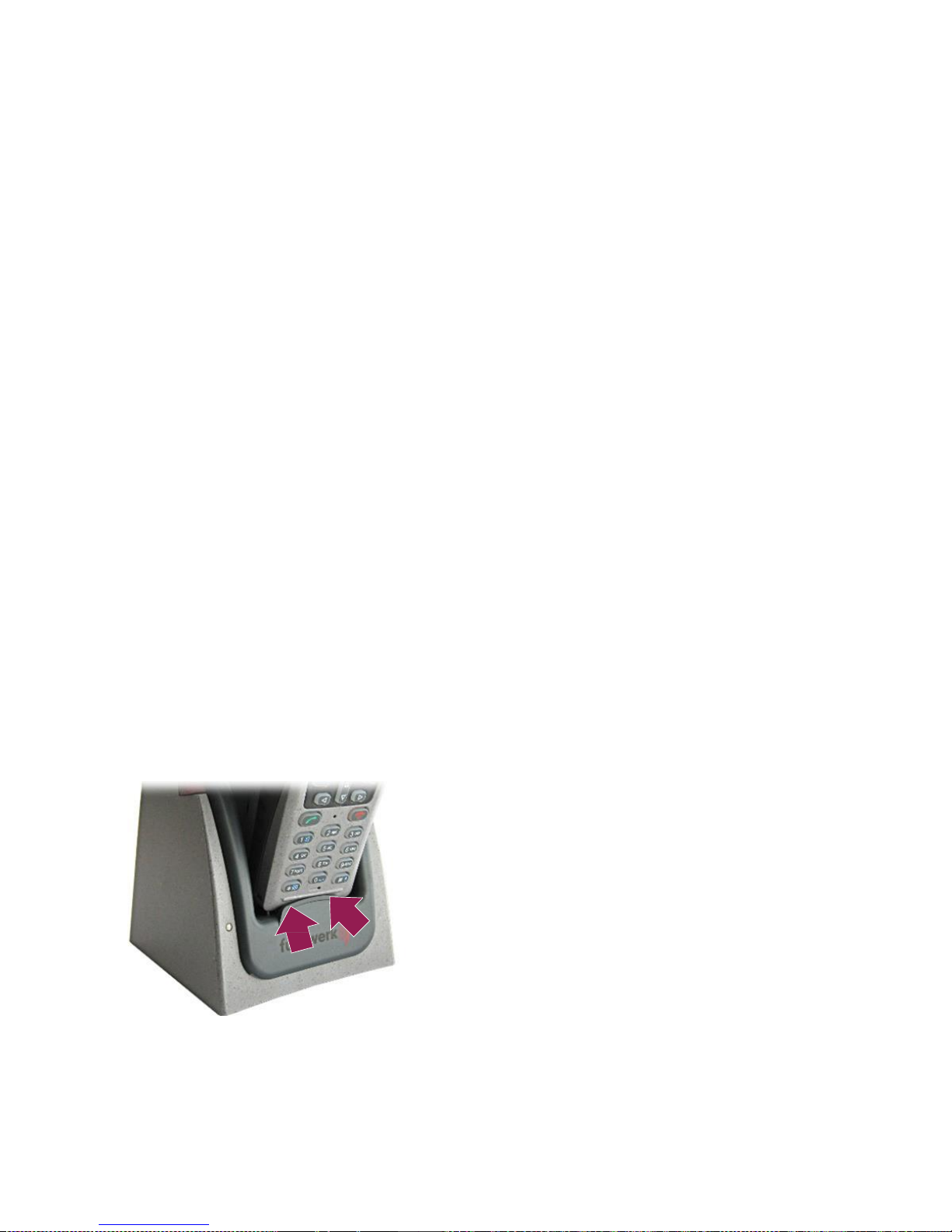
54 First steps
Charging the battery
Charging the battery
Always charge batteries with the system-compatible chargers supplied by Funkwerk.
These are optimally suited for the radio set and the battery. Always use the chargers
outside of hazardous areas (explosive atmospheres).
Charging the battery with a FT4 Desktop Charger II / FT4 Desktop
Station
The Desktop Charger II FT4 and Desktop Station FT4 chargers charge both the
battery in the radio set and a spare battery. When the radio set and the spare battery
are connected with the charger at the same time, the battery in the radio set is
charged first. After this, the charging process of the spare battery starts. The charging time for an empty battery is roughly 5 to 8 hours.
Connect the charger to the power supply
Carry out the following work steps:
1. Connect the plug-in power supply unit with the charger.
2. Plug the plug-in power supply unit into a suitable power outlet.
Done.
Placing the radio set into the charger
Carry out the following work steps:
1. Place the radio set with its bottom into the charger.
Page 59

First steps 55
Charging the battery
2. Carefully push the radio set into the charger until the lock engages.
The charging process starts.
The charging status of the battery is shown on the radio set display, see section
„Signalling the charging status“
(p.
59)
Done.
Removing the radio set from the charger
Carry out the following work steps:
1. Push the unlocking knobs of the charger together.
Page 60

56 First steps
Charging the battery
2. Remove the radio set carefully from the charger.
Done.
Inserting the spare battery into the charging slot
Carry out the following work steps:
1. Place the bottom of the battery into the charging slot on the rear.
Page 61

First steps 57
Charging the battery
2. Carefully push the battery into the charging slot until the lock engages.
The charging process starts.
The charging status of the battery is indicated by the LED on the front of the char-
ging slot, see section „Signalling the charging status“
(p.
59).
Done.
Removing the spare battery from the charger
Carry out the following work steps:
1. Carefully push the unlocking element on the charger upwards.
Page 62

58 First steps
Charging the battery
2. Remove the battery carefully from the charging slot.
Done.
The battery is now charged.
Charging the battery with a FT4 Travel Charger
This charger charges the battery in the radio set. This charger is perfect for travelling
due to its compact design. The charging time for an empty battery is roughly 5 to 8
hours.
Carry out the following work steps:
1. Hook the holding clip of the charger into the recess in the radio set.
Page 63

First steps 59
Charging the battery
2. Carefully push the charger towards the radio set until the unlocking tab hooks into
the recess on the radio set.
3. Plug the plug-in power supply unit into a suitable power outlet.
The charging process starts.
The charging status of the battery is shown on the radio set display, see section
„Signalling the charging status“
(p.
59)
The battery is now charged.
Signalling the charging status
The battery charging status is displayed by the following symbols on the display of
the radio set.
Battery charging status: Symbols in the radio set display
Symbol
Battery status
The battery is being discharged. The bright bar indicates the available
capacity.
The battery is empty.
The radio set is in the charger. Battery is being charged
The radio set is in the charger. The battery is fully charged.
The radio set has identified a faulty battery.
The charging status is also indicated by the LEDs of the radio set, see chapter
„Structure and function“ > „Illuminated indicators“
(p.
38).
Page 64

60 First steps
Charging the battery
The indicator light on the charger indicates the charging status of the spare battery.
Indicator light of "Desktop Charger II FT4" charger
Meaning of charger indicator light
Colour
Status
Meaning
OFF
The charger is not connected to mains.
yellow
lit
The spare battery is not inserted.
red
flashing
The spare battery is defective or is not properly inserted.
lit
The spare battery is being charged. If the radio set is in
the charger, the charging process of the spare battery
starts as soon as the battery in the radio set is fully
charged.
green
lit
The spare battery is fully charged. This indicator is
independent of the charging status of the radio set in
the charging set.
Page 65

TETRA basics 61
Safety information
TETRA basics
In this chapter, you can familiarise yourself with the basics and functions of the
TETRA system.
Safety information
If the radio set is not logged into the personal emergency signal centre, the TETRA
emergency call cannot be transmitted if radio contact is unavailable due to insufficient
radio coverage. Transmit the TETRA emergency call one more time as soon as the
radio connection is re-established.
TETRA connection types
Due to the TETRA transmission technology, your radio set can set up different connections with other subscribers. The following TETRA connection types are possible,
depending on the situation and the application:
Trunking mode (TMO)
(p.
62)
Direct mode (DMO)
(p.
64)
Page 66

62 TETRA basics
TETRA connection types
Trunking mode (TMO)
The trunking mode is a connection type for which all terminal units use a common
TETRA infrastructure. All terminal units that can be reached are registered on the
TETRA network.
Description
In trunking mode, your radio set sets up all connections from or to other users and
other applications through the TETRA infrastructure.
TMO
TMO
uplink
downlink
uplink
downlink
PABX
PSTN
downlink
uplink
Application
Trunking mode (TMO): Schematic representation of possible calls and connections
In trunking mode, voice and data calls can be made simultaneously.
Page 67

TETRA basics 63
TETRA connection types
Identification features
The following features of your radio set enable you to identify that your radio set is
connected with the TETRA network and that the trunking mode is activated:
Trunking mode (TMO): Identification features on your radio set
Legend
Identification feature
Behaviour
Display
Idle display reads TMO.
Left signal LED
green, flashing slowly
Activating the trunking mode
After registering in the TETRA infrastructure, the radio set is in trunking mode (TMO)
and is ready for operation.
Activating the trunking mode manually
If your radio set does not automatically change over to trunking mode (TMO), you
can activate this mode manually.
Prerequisite:
The radio set must be located within the radio coverage range of the TETRA inf-
rastructure.
Carry out the following work steps:
1. On the display, navigate to MAIN MENU > SETTINGS > NETWORKS.
The NETWORK menu is displayed.
2. Highlight the TMO menu item using the cursor keys.
Page 68

64 TETRA basics
TETRA connection types
3. Press the ‹Right softkey› key to select the menu item.
Done.
Direct mode (DMO)
The direct mode is a connection type in which the terminal units communicate directly
with one another.
Description
In direct mode, your radio set sets up all connections from or to other subscribers
directly and without using the TETRA infrastructure. The subscribers must be within
the transmit range of your radio set.
DMO
Direct mode (DMO): Schematic representation of possible calls and connections
Page 69

TETRA basics 65
TETRA connection types
Identification features
The following features of your radio set indicate to you that the direct mode is activated (in idle mode, without an active voice connection):
Direct mode (DMO): Identification features on your radio set
Legend
Identification feature
Behaviour
Display
Idle display reads DMO.
Left signal LED
green, flashing slowly
Activating the direct mode manually
If your radio set is not switched to direct mode (TMO), you can activate this mode
manually. Ensure that other subscribers are within the range so you can communicate in this mode.
Carry out the following work steps:
1. On the display, navigate to MAIN MENU > SETTINGS > NETWORKS.
The NETWORK menu is displayed.
2. Highlight the DMO menu item using the cursor keys.
3. Press the ‹Right softkey› key to select the menu item.
Done.
Page 70

66 TETRA basics
TETRA connection types
Page 71

Operation 67
Switching on the radio set
Operation
In this chapter, you can familiarise yourself with the operation of the radio set. Frequent operation steps are described on the following pages.
Switching on the radio set
PLEASE NOTE
Operating radio sets may cause disturbances!
Switching on or operating your radio set may cause a hazard to you or to other persons.
Switch on your radio set only if its operation does not expose any persons to a
hazard.
Do not switch your radio set on in places where the operation of radio sets is not
permitted.
Carry out the following work steps:
Press the ‹Hang up› key long.
The display and keyboard illumination is switched on.
The radio set carries out a self-test. This will take a few seconds.
The radio set is connected with the TETRA infrastructure (if this has been pro-
grammed).
The display shows the idle display.
Done, the radio set is switched on.
Page 72

68 Operation
Switching off the radio set
Switching off the radio set
PLEASE NOTE
Battery will self-discharge while radio set is switched off!
The self-discharge of the battery while the radio set is switched off may impair readiness for operation of the radio set!
Place the radio set in a charger to charge the battery.
Charge the battery regularly if it is not in use for a prolonged period of time.
Observe the safety instructions for storage and transport of the battery, see
chapter „Safety information“ > „Battery“
(p.
21).
Carry out the following work steps:
1. Unlock keyboard (if necessary).
2. Press the ‹Hang up› key for about three seconds.
The radio set cuts the connection.
The display and keyboard illumination is switched off.
The radio set switches itself off after a short time.
3. Charge the battery, see chapter „First steps“ > „Charging the battery“
(p.
54).
Done, the radio set is switched off.
Page 73

Operation
69
Menu
Menu
The radio set makes numerous functions available to you. Many of these functions
can be called up in the menu in a structured way.
Navigating the menu
The following pages tell you how to navigate through the menu for executing a function when starting from the idle display.
Prerequisite:
The display shows the idle display.
Carry out the following work steps:
1. Press the ‹Right softkey› key to display the menu.
The display shows the main menu.
Page 74

70
Operation
Menu
2. Highlight the desired menu item using the cursor keys.
Every time a key is pressed, the adjacent menu item is highlighted in the display.
3. Press the ‹Right softkey› key to select the highlighted menu item.
The display shows the menu.
Page 75

Operation
71
Menu
4. Highlight the desired menu item using the cursor keys.
Every time a key is pressed, the adjacent menu item is highlighted.
5. Press the ‹Right softkey› key to select the highlighted menu item.
The function is executed. Or: The display shows the menu which is subordinate to
the selected menu item.
Done.
TIP
After a prolonged inactivity period, the display switches to the screen saver, see
section „Screen saver“
(p.
44).
Page 76

72
Operation
Menu
Changing back to the previous menu
If you have executed the desired function or if you simply wish to go back, you can go
back as follows:
Prerequisite:
The display shows a menu.
Carry out the following work steps:
1. Press the ‹Left softkey› key briefly when the BACK fu nction is shown in the dis-
play.
The display content changes back to the previous content.
2. Repeat pressing the key if required.
Done.
Page 77

Operation 73
Group calls
Group calls
Group calls are voice connections a subscriber sets up to several other subscribers
at the same time. While one subscriber speaks, the other subscribers in that group
listen to this call.
Selecting a group
You can select a group with which you communicate mainly from the
P
REFERRED
GROUPS list. From now on, pressing the ‹PTT (transmit key)› key will automatically
start a group call for this group. If the list is not programmed, the display shows the
GROUP LIST list. Select the desired group from this list.
Prerequisite:
The display shows the idle display.
Carry out the following work steps:
1. If required, press ‹Volume/group call› knob longer in order to enable its function
as a rotary switch.
Page 78

74 Operation
Group calls
2. Press button ‹Volume/group call› briefly.
The display shows the GROUP LIST OR PREFERRED GROUPS field.
? The display shows the VOLUME field, not the GROUP LI ST field?
The ‹Volume/group call› knob allows both setting the volume and selecting
groups.
Press knob ‹Volume/group call› to switch between the VOLUME field and the
Group list field.
3. Turn ‹Volume/group call› knob until the desired group is highlighted.
Page 79

Operation 75
Group calls
4. Press the ‹Right softkey› key to execute the SELECT function, or press the
‹Volume/group call› knob again briefly.
This setting is saved.
The display shows the idle display again. In the idle display, the selected group is
shown.
Done.
TIP
The group selection sub-menu can also be accessed from the idle display, using
either the MENU > ADDRESSES > PREFERRED GROUPS or MENU > ADDRESSES >
GROUP LIST paths. The group selection function of the rotary control may have been
blocked while programming the radio set.
Page 80

76 Operation
Group calls
Starting a group call
A group call is a semi-duplex voice connection. While one subscriber speaks, all
other subscribers in that group listen to this call. After that, the other subscribers can
answer the call, one after the other.
Prerequisite:
The channel is not occupied by a call.
Carry out the following work steps:
1. Push key ‹PTT (transmit key)› and keep it pressed.
The connection with the subscribers in the called group is set up. The display
shows the name or the call number of the group (GSSI).
After a short time, your speaking enable signal is transmitted unless another
subscriber is transmitting. The display additionally shows your name or your call
number (ISSI).
Page 81

Operation 77
Group calls
2. Keep ‹PTT (transmit key)› key pressed while speaking.
3. After speaking, release key ‹PTT (transmit key)›.
4. Continue the conversation:
Hold the ‹PTT (transm it key)› key down to talk.
Release the ‹PTT (transmit key)› key to listen.
When neither you nor any other group members are talking, the connection is terminated after a pre-set period of time. To start another call to the group, start
again at step 1.
Done.
Page 82

78 Operation
Group calls
Receiving a group call
An incoming group call from a member of the the selected group is automatically
received by your radio set. You do not have to do anything to accept the call.
During a group call, the following information is displayed on the display of your radio
set:
Name or call number of called group
Name or call number of subscriber who is currently speaking
Display content while receiving a group call
Page 83

Operation 79
Group calls
Answering a group call
Prerequisite:
Your radio set receives a group call.
Carry out the following work steps:
1. Wait for the calling subscriber to stop speaking.
The display shows only the call number of the group (GSSI) or its name. The
lower icon with the blue arrow is no longer displayed.
Page 84

80 Operation
Group calls
2. Push key ‹PTT (transmit key)› and keep it pressed.
After a short time, your speaking enable signal is transmitted unless another
subscriber is transmitting. The display additionally shows your name or your call
number (ISSI).
3. Keep ‹PTT (transmi t key)› key pressed while speaking.
4. After speaking, release key ‹PTT (transmit key)›.
You may now be able to hear other subscribers.
As soon as no more subscriber answers, the connection is disconnected after a
pre-set time.
Done.
Page 85

Operation 81
Group calls
Scanner function
If the scanner function is activated, your radio set will scan the radio communications
in multiple groups simultaneously. If the radio set receives a call from one of the
groups being scanned, the speaker is switched on automatically, and the hands-free
mode is activated. To use the scanner function, you must
Select a scan list and
activate the scanner function.
Selecting a scan list
The groups to be scanned are grouped in scan lists. To use the scanner function, you
must select at least one scan list.
Carry out the following work steps:
1. On the display, navigate to MAIN MENU > ADDRESSES> SCA N LISTS.
The SCAN LISTS menu is displayed.
2. Highlight the desired menu item using the cursor keys.
3. Press the ‹Right softkey› key to execute the function
O
PTIONS
.
The OPTIONS menu is displayed.
4. Highlight the SELECT menu item using the cursor keys.
Page 86

82 Operation
Group calls
5. Press the ‹Right softkey› key to execute the function
S
ELECT
.
The display changes back to the SCA N LISTS menu. The desired scan list is
marked there as "selected".
Done.
TIP
To find out which groups are summarised in the scan lists, highlight the function
SHOW in work step 4 instead of the SELECT function.
Page 87

Operation 83
Group calls
Switching the scan function on/off
You can switch the scan function on and off at any time when a scan list is marked as
"selected". When a scan list is selected and activated, your radio set monitors the
radio traffic in all associated groups. When receiving a call, the hands-free talking
mode is activated and the loudspeaker is switched on.
Carry out the following work steps:
1. On the display, navigate to MAIN MENU > ADDRESSES> SCA N LISTS.
The SCAN LISTS menu is displayed.
2. Highlight the ACTIVATE SCANNING entry using the cursor keys.
3. Press the ‹Right softkey› key to execute the function
S
ELECT
.
After a short time, the title of the menu item changes from ACTIVATE SCA NNING to
DEACTIVATE SCANNING.
The scan function is now active.
The symbol of the "selected“ scan lists changes as follows:
The idle display screen shows the message "Scanning groups".
Page 88

84 Operation
Individual calls
4. If required, press the ‹Right softkey› key one more time to deactivate the scan
function again.
Done.
TIP
The scan function is active when the title of the menu item is DEACTIVATE SCANNING
.
The scan function is inactive when the title of the menu item is ACTIVATE SCANNING.
Leaving a group call early
Given the large number of group calls that you receive with your radio set, not all
information may be important for you. If required, you can therefore leave a group call
early.
Prerequisite:
Your radio set receives a group call.
Carry out the following work steps:
Press the ‹Hang up› key briefly.
The connection is disconnected.
The radio set ignores the active group call.
Done.
Individual calls
Individual calls are voice connections between two individual subscribers. Individual
calls are always started by entering the desired call number. Individual calls can be
set up in the following ways:
as a full-duplex voice connection, see section Duplex mode
as a half-duplex voice connection, see section „Two-way call (direct through)“
(p.
88)
Page 89

Operation 85
Individual calls
Duplex mode
An individual call in duplex mode is a full-duplex voice connection in which you hold
the radio set near your ear just like a telephone set. During this time, both you and
the called subscriber can listen and speak at the same time.
Starting a call
Prerequisite:
The display shows the idle display or the screen saver.
Carry out the following work steps:
1. Enter the call number. Choose one option:
Entering the call number using the number keys.
Selecting the call number from the subscribers' list: Navigate to MAIN MENU >
ADDRESSES >USER LIST in the display and highlight the desired user.
The condition as shown appears in the following cases:
After entering the call number in the idle condition.
After highlighting the user in the user list and ‹Calling›.
After marking the user and ‹Picking up›.
Starting from this display, start the call by ‹Picking up›.
Page 90

86 Operation
Individual calls
2. Press the ‹Right softkey› key if the CALLING function is available to select a
gateway (telephone, TETRA, ...) , then press the ‹Pick up› key. Or, after marking
a user in the user list, press the ‹Pick up› key twice.
The connection is set up.
The display shows the call number or the name of the called subscriber.
As soon as the called party accepts the call, the connection is set up.
3. Hold the radio set close to your ear like a telephone receiver for listening and
speaking.
Done.
TIP
The settings of your radio set are individually programmed by the radio set operator.
You may be able to start a call to a pre-set target by means of a speed dialling key as
well. If you have any questions, please contact the responsible system administrator
for your communication facilities.
Page 91

Operation 87
Individual calls
Accepting a call
Prerequisite:
Your radio set signals an incoming individual call.
Carry out the following work steps:
1. Press the ‹Pick up› key.
The connection is now set up.
2. Hold the radio set close to your ear like a telephone receiver for listening/spea-
king.
Done.
Terminating a call
Carry out the following work steps:
Press the ‹Hang up› key.
The connection is disconnected.
Done.
Page 92

88 Operation
Individual calls
Two-way call (direct through)
At the factory, two-way calls are configured in "direct through" mode. A call in the
"Direct Through" mode is a half-duplex voice connection during which you alternatingly set the radio set to transmit mode (by keeping the PTT button pressed) or in
receive mode (by releasing the PTT button). The hands-free talking mode is activated, and the loudspeaker is on. The called subscriber does not need to accept the
call to hear you. Either you or the called user can speak.
Starting a call
Prerequisite:
The display shows the idle display or the screen saver.
Carry out the following work steps:
1. Enter the call number. Choose one option:
Entering the call number using the number keys.
Selecting the call number from the subscribers' list: Navigate to MAIN MENU >
ADDRESSES >USER LIST in the display and highlight the desired user.
The condition as shown appears in the following cases:
After entering the call number.
After highlighting the user and ‹Calling›.
After highlighting the user and actuating (pressing or releasing) the ‹PTT
(transmit key)› key.
Starting from this display, start the call with the ‹PTT (transmit key)› key (thumb,
keep pressed and talk; release and listen).
2. Press the ‹Right softkey› key if the CALLING function is available, then press the
‹PTT (transmit key) › key and hold it down. Or, after highlighting a user from the
Page 93

Operation 89
Individual calls
user list, press the ‹PTT (transmi t key)› key twice and keep it pressed after pressing the second time.
The connection is established as soon as the display shows the call number or
name of the called subscriber.
The called subscriber can hear you.
3. Hold the radio set next to your head a little at the side of the mouth for listening
and speaking.
4. Keep the ‹PTT (transmit key)› key pressed for speaking.
5. To listen, release the ‹PTT (transmit key)› key.
Done.
TIP
The settings of your radio set are individually programmed by the radio set operator.
You may be able to start a call to a pre-set target by means of a speed dialling key as
well. If you have any questions, please contact the responsible system administrator
for your communication facilities.
Page 94

90 Operation
TETRA Emergency Calls
Terminating a call
Carry out the following work steps:
Press the ‹Hang up› key.
Done.
TIP
When neither you nor the called subscriber are speaking, the connection is cut automatically after a certain period.
TETRA Emergency Calls
Triggering a TETRA em ergency call starts a group call of a particular priority. Use this
function only when you are in an emergency situation.
Special features
So long as the radio set is logged into the personal emergency signal centre, triggering the emergency call will generate a "personal alarm" and transmit it to the personal emergency signal centre. A TETRA emergency call is only possible when the
radio set has not logged into the personal emergency signal centre.
During an active TETRA emergency call connection, the radio set works with the following restrictions:
The scan function is deactivated. Group monitoring is not carried out.
Individual calls cannot be received.
Page 95

Operation 91
TETRA Emergency Calls
Triggering a TETRA emergency call
Prerequisite:
The radio set is switched on.
Carry out the following work steps:
1. Press the ‹Alarm› key long.
All services, e.g. a voice connection, are terminated.
The radio set starts a group call with a particular priority.
The hands-free talking mode is activated and the loudspeaker is on.
The emergency call connection appears on the display on a red background.
The radio set is now in TETRA emergency call mode.
2. Hold the radio set clearly away from your head for listening and speaking (open
listening / hand-free talking).
Push the ‹PTT (transmit key)› key and keep it pressed.
To listen, release the ‹PTT (transmit key)› key.
Done.
Page 96

92 Operation
TETRA Emergency Calls
Terminating a TETRA emergency call
When neither you nor the called subscribers are no longer speaking, the connection
is cut automatically after a certain period. Otherwise, you can terminate the emergency call by hand.
Carry out the following work steps:
Press the ‹Hang up› key to terminate the connection.
Done.
Page 97

Operation 93
Messaging
Messaging
Message types
For sending and receiving text messages, the following text message types are being
differentiated.
Text message types on radio sets Funkwerk FT 4
Designation
Type
Behaviour of the Funkwerk FT 4
radio set for reception
Status
message
Pre-defined, non-modifiable text message
(The transmission is bitcoded and is possible
from and to any radio of
the FT4 series. Prerequisite for a successful
communication is that
the allocation of bit
combinations and text
messages is programmed in the same way on
your radio set and the
receiver's unit and have
the same meaning.)
Alert tones and display content.
After executing the OK function (press
‹Right softkey› key), the message is
no longer accessible.
The message indicator on the display
disappears. The message is not being
saved.
SDS text
message
Text message that is
individually composed
(Message is transmit-
ted in clear text and
transmission is possible from and to any
TETRA-compatible terminal unit.)
Alert tones and display content.
After executing the OK function (press
‹Right softkey› key), the message is
no longer displayed.
The message is saved in the post box.
It can be displayed again later.
Page 98

94 Operation
Messaging
Composing an SDS text message
An SDS text message is a text message that you can compose individually.
Prerequisite:
The display shows the idle display.
Carry out the following work steps:
1. On the display, navigate to MENU > MESSAGES> NEW MESSAGE.
The empty SDS EDITOR window is displayed.
2. Entering text:
Enter letters with keys ‹2 to 9, 0›.
Enter digits with keys ‹1 to 9, 0›.
Enter special characters with keys ‹1› and ‹*›.
Switch between capitalization and non-capitalization with the ‹#› key.
As long as no text has been entered, the footer (left softkey) shows the DELETE
element INSTEAD OF BACK. The display of the left softkey changes to the DELETE
only after the first character has been entered.
Page 99

Operation 95
Messaging
3. Press the ‹Right softkey› key to execute the OPTIONS function.
The displayed text is accepted including all changes.
The SDS EDITOR OPTIONS window is displayed.
4. Transmit the message, see section „Transmitting an SDS text message“
(p.
100).
Done.
Page 100

96 Operation
Messaging
Composing an SDS text message from a template
An SDS text message is a text message that you can compose individually. In
practice, similar information is often transmitted repeatedly. For this reason, your
radio set is programmed with pre-defined, frequently used text blocks. These text
messages can be transmitted directly, but you can also modify and supplement them
before sending them.
Prerequisite:
The display shows the idle display.
Carry out the following work steps:
1. On the display, navigate to MENU > MESSAGES>
T
EMPLATES
.
The TEMPLATES window is displayed.
2. Highlight the desired template using the cursor keys.
 Loading...