

Page 1
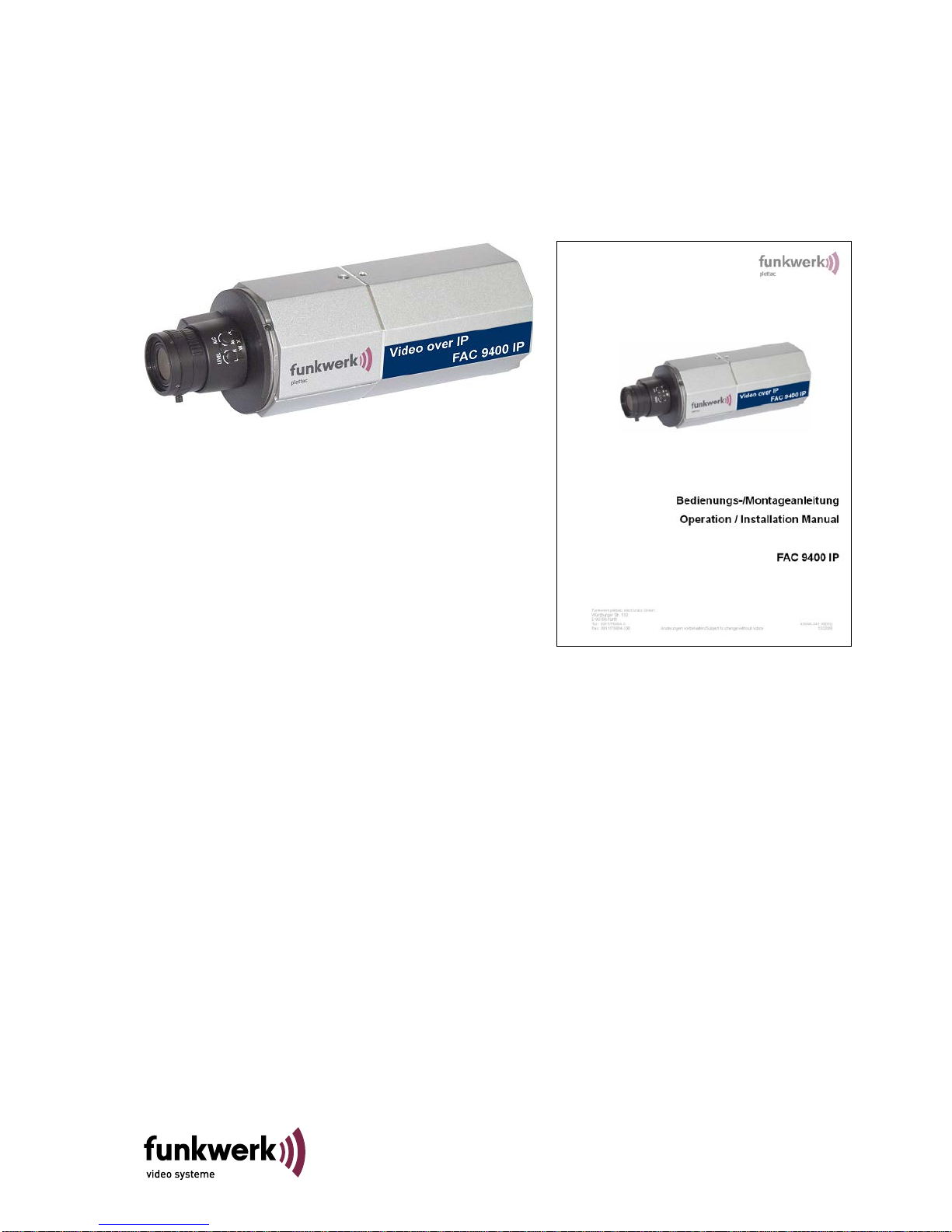
Bedienungs-/Montageanleitung
Operation / Installation Manual
FAC 9400 IP
Funkwerk video systeme GmbH
Thomas-Mann-Str. 50
D-90471 Nürnberg
Tel.: 0911 75884-0 Änderungen vorbehalten 03/2015
Fax: 0911 75884-100 Subject to change without notice 43046-941.00(02)
Page 2

Inhaltsverzeichnis/Contents
(D) Deutsch 3
Sicherheitshinweise 3
Allgemeine Beschreibung 4
Wartung 4
Hilfe bei Störungen 4
Lieferumfang 5
Entsorgung 5
Montagehinweise 5
Steckerbelegungen und Leuchtdiodenbezeichnungen 6
15 pol. D-SUB Buchse (Verbindung zur Kamera) 11
2-pol. JST-Stecker (On-Air-LED) 11
Zubehör für FAC 9400 IP 12
Inbetriebnahme / Konfiguration 12
Auslieferzustand: 12
Notwendiges Zubehör zur Erstinbetriebnahme / Konfiguration 12
Inbetriebnahme und Konfiguration der FAC 9400 IP Kamera 12
Technische Daten 16
Maßbilder FAC 9400 IP-Kamera 17
(GB) English 19
Safety guidelines 19
General description 20
Maintenance 20
Help with faults 20
Scope of delivery 21
Disposal 21
Assembly instructions 21
Pin assignment and LED designations 22
15-pin D-SUB jack (connection to the camera) 27
2-pin JST plug (On-Air-LED) 27
FAC 9400 IP accessories 28
Commissioning/configuration 28
Delivery state: 28
Necessary accessories for initial commissioning/configuration 28
Commissioning and configuration of the FAC 9400 IP camera 28
Specifications 32
Dimensioned drawings of the FAC 9400 IP camera 33
FAC 9400
03/2015
2
Page 3

(D) Deutsch
Sicherheitshinweise
Alle Einstellvorgänge bei Inbetriebnahme und Service werden überwiegend über die
Steuerschnittstelle (LAN) bzw. die Web-Seite, immer bei geschlossenem Gerät
ausgeführt. Das Gerät darf nur im Werk durch geschulte und autorisierte Personen
geöffnet werden, da sonst auch mit Langzeitbeschädigungen und Ausfall des
Kühlsystems zu rechnen ist!
Bei Schäden durch Nichtbeachten der Bedienungsanleitung oder Öffnen des Geräts
erlischt der Garantieanspruch.
Für Folgeschäden wird keine Haftung übernom men!
Die FAC 9400 IP darf nur bestimmungsgemäß eingesetzt und nicht außerhalb seiner spezifizierten
Betriebs- und Umgebungsbedingungen betrieben werden.
Die FAC 9400 IP darf nur von autorisiertem Fachpersonal montiert werden.
Geltende Sicherheitsbestimmungen und Unfallverhütungsvorschriften sind zu beachten.
Vor Montage- oder Servicearbeiten Betriebsspannu ng abs c halt en.
Bei Montage- und Servicearbeiten dürfen nur Originalteile verwendet werden.
Der Montageort muss sich in einer Blitz-Schutzzone LPZ 3.
Die vorgeschriebenen minimalen Biegeradien der Kabel müssen eingehalten werden.
Die vorgeschriebenen Entstörmaßnahmen sind einzuhalten
3
FAC 9400
03/2015
Page 4

Allgemeine Beschrei bung
Die FAC 9400 IP ist eine IP Kamera die bis zu zwei unterschiedliche Auflösungen mit einem digitalen
Signalprozessor (DSP), einen Video-, Audio.- und I/O Anschluss, der Videoüberwachungssysteme sehr
leistungsfähig mit LAN oder Internet unterstützt.
Die Advanced Simple Profile MPEG-4 Codierung bietet gegenüber vorher genutzten Standards bei gleicher
Netzlast erheblich bessere Bildqualität bei dynamischen Bildsequenzen. Das ist für die Übertragung und
Aufzeichnung ein sehr wichtiger Vorte i l.
Die Konfiguration kann über Funkwerk Managementsystem p.o.s.a. und LAN-PGE erfolgen. Über Webbrowser
HTML können separat die FAC9400 Encoder Parameter geändert werden. Bei Auftreten von Alarmen können
MPEG-4 Sequenzen konfigurierbar in Länge (auch Vorgeschichte), Bildrate und Bildqualität im lokalen Speicher
aufgezeichnet werden. Das alarmauslösende Ereignis wird außerdem auch an ein zentrales
Managementsystem weitergeleitet. Livebilder und gespeicherte Sequenzen werden über LAN in die
Überwachungszentrale übertragen.
Abhängig von der Netzwerkstrategie des Kunden können von Breitband-LAN über ISDN bis hin zu GSM alle
vorhandenen Netze mit MPEG 4 „advanced“ und/oder „Standard“–Profile bei voller Auflösun g genut zt werde n.
Die eingesetzte Lösung lässt dem Kunden des Weiteren die Wahlmöglichkeit einer frei skalierbaren MindestBildqualität bei variabler Bil drat e zur Min imierung der Netzlast. Die Spannungsversorgung kann wahlweise über
PoE oder durch ein externes Netzteil mit 12V DC bis 29V DC erfolgen. Der Klinkenstecker für die externe
Stromversorgung ist verriegel bar .
Hinweis:
Diese Bedienungsanleitung ist nur für den Anschluss der FAC 9400 IP und die ersten Schritte der
Inbetriebnahme anzuwenden. Details, Spezielle Einstellungen und Funktionshinweise sind der Technischen
Dokumentation 43524920.00 (nur Encoder) für VNS-Komponent en und der Beschreibung der jeweiligen
FAC940 zu entnehmen.
Wartung
Die elektrische Sicherheit (Stromversorgung) ist regelmäßig zu überprüfen. Bei Wartungsarbeiten ist die
Stromversorgung immer auszuschalten. Zum Reinigen nur lösungsmittelfreie Reinigungsmittel drucklos
verwenden.
Hilfe bei Störungen
Keine Funktion (LED’s alle aus) Betriebsspannung überprüfen
Kein Bild Überprüfung aller Anschlüsse sowie der gesamten Konfiguration
Weitere Funktionsstörungen siehe Technische Dokumentation VNS
Bei weitergehenden Störungen autorisiertes Servicepe rs onal benachrichtigen. Bei entsprechendem Abschluß
eines Wartungsvertrages stehen im Werk kurzfristig Tauschgeräte zur Verfügung.
Funkwerk video systeme GmbH
Reparatureingang DE
Thomas-Mann-Str. 50
D-90471 Nürnberg
Tel. 01805 671205
Fax 0911/75884-100
E-Mail: stoerung@funkwerk-vs.com
www.funkwerk-vs.com
FAC 9400
03/2015
4
Page 5
Lieferumfang
• Die FAC 9400 IP Best.-Nr. 943046120100 od. 943046120200 od. 943046120300
• Steckverbindung für Stomversorgung, Audio und I/O
• CD mit ausführlicher Dokumentation und Streaming Plugin SW
Entsorgung
Entsorgen Sie das Gerät entsprechend den geltenden gesetzlichen Vorschriften.
Montagehinweise
Die Montage der Kamera erfolgt z.B mittels ¼“ Gewindeschraube auf handelsüblichen Stativen
5
FAC 9400
03/2015
Page 6
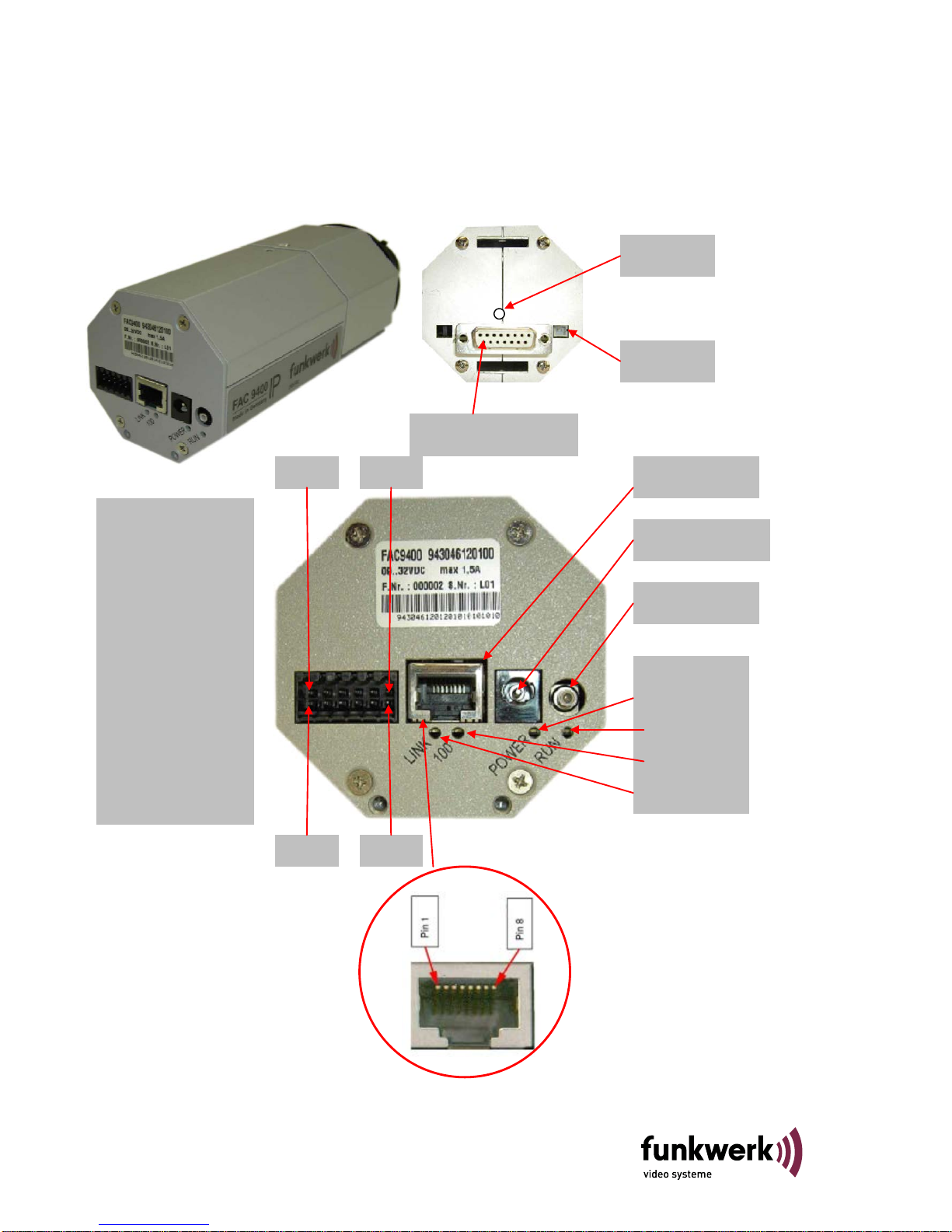
Steckerbelegungen und Leuchtdiodenbezeichnungen
RJ 45-„LAN“
SMB „Video““ (VBS)
Weidmüller 12pol.
Pin. Signal
13. ST1 Camera
14. GND zu ST1 (Cam)
15. Line In +
16. Line In -
17. Line Out +
18. Line Out -
19. Out +
20. Out -
21. In +
22. In -
23. ST2 Camera
24. GND zu ST2 (Cam)
LINK
100
POWER
Leuchtdioden
Pin1
Pin 2
RUN
Pin11
Pin 12
Spannungsversorgung
15pol. D-SUB zur Kamera
ON-AIR-LED
Reset-Taster
FAC 9400
03/2015
6
Page 7
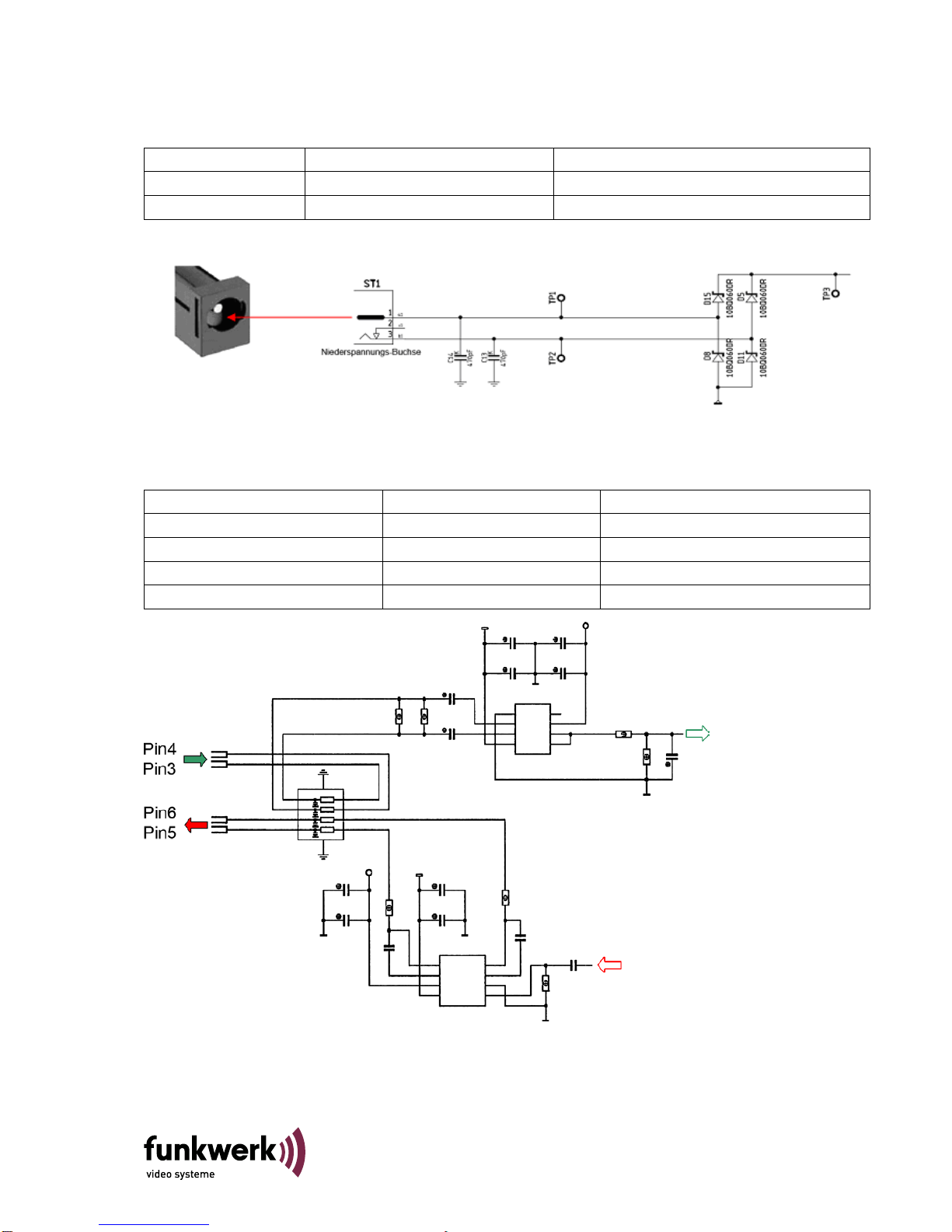
Spannungsversorgung der FAC 9400 IP
Die Spannungsversorgung erfolgt über den 2-poligen Klinkenstecker an der Rückseite der FAC9400 od. über PoE.
Signal Niederspannungsbuckse (Klinkenstecker) Beschreibung
UB 1 + Pol (Power min. 12 bis max. 29 VDC)
GND 2 - Pol (Ground)
Audio (symetrisch In/Out)
Die analogen Audiosignale wer den üb er den 12po ligen W eidm üller -Stecker an der Rückseite der FAC 9400 IP
zur Verfügung gestellt.
Signal Weidmüller-Siftleiste Pin Beschreibung
Line IN + 3 Line In – (Signal)
LINE IN - 4 Line In – (GND)
LINE OUT + 5 Line Out (Signal)
LINE OUT - 6 Line Out (GND)
7
FAC 9400
03/2015
Page 8
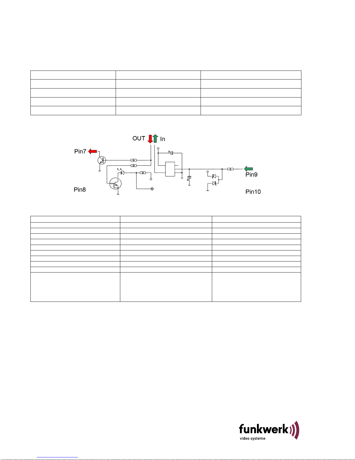
Digitale I/O
Der Anschluss der digitalen Ein- und Ausgänge erfolgt ebenfalls über den 12-poligen Weidmüller-Stecker an der
Rückseite der FAC 9400 IP. Weder der Eingang noch der Ausgang sind potentialgetrennt.
Signal Weidmüller-Siftleiste Pin Signal
OUTPUT 7 OUT+- (Ausgang 1) Signal
GND 8 OUT- (Ausgang 1) GND
INPUT 9 IN1+ (Eingang 1) Signal
GND 10 IN- (Eingang1) GND
Faktor
Eingang
Ausgang
Spannungsbereich
Max. 15 VDC
Max. 28 VDC
Einschaltschwelle
ca. 2,6 V -
Ausschaltschwelle
ca. 2,2 V -
Widerstand
10 kΩ Pull-Up an 3,3 V DC -
HW-Laufzeit
ca. 3,5 ms -
Schaltleistung
-
100 mA
Schnittstellentyp
TTL
„Open Collector“
Überspannungsschutz
Suppressordiode
Suppressordiode
Verpolungsschutz
Kein Verpolungsschutz
-
SW-Latenzzeit
Die Abtastfrequenz bei den digitalen Inputs
beträgt 40 ms. Ist der Zustand eines digitalen
Inputs bei zwei aufeinander folgenden
Abfragen gleich, wird dieser Zustand
übernommen. D.h. ein Signal muss >= 80 ms
(Pulslänge) anliegen.
FAC 9400
03/2015
8
Page 9

Steuerleitungen der Kamera
Die beiden Steuerleitungen der Kamera sind ebenfalls über den 12-poligen Weidmüller Stecker an der
Rückseite der FAC 9400 IP zugänglich. Die Belastbarkeit der Ausgän ge li egt be i max. 50 mA je Ausgang.
Signal Weidmüller-Siftleiste Pin Signal Weidmüller-Siftleiste Pin
ST1 1 ST2 11
GND zu ST1 2 GND zu ST2 12
Steuereingänge:
Anschluss für einfache
Fernbedienung, Eingänge
intern über Pull-upWiderstände 22 kΩ an +5 V,
Aktivierung gegen
Low(Videomasse)
Steuerausgänge:
Über 100 Ω
Serienwiderstand wird
gegen Masse geschaltet,
Imax=50 mA
Überspannungsschutz:
Begrenzung statischer
Spannungen über Dioden
bei ca. < -1 V und > +6 V
9
FAC 9400
03/2015
Page 10
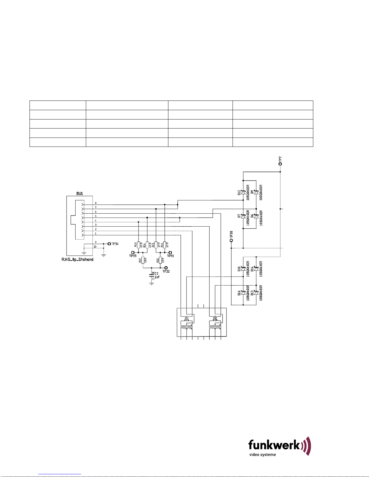
LAN-Schnittstelle
Die LAN Schnittstelle entspricht dem Standard IEEE802.3af mit 10/100Mbit (autosense) über Cat-5 Kabel
(10/100BaseT). Als LAN-Anschluss steht ein RJ45 Stecker an der Rückseite der FAC 9400 IP mit der
Bezeichnung „LAN“ zur Verfügung. Die Stromversorgung der Kamera kann u.a. auch über PoE erfolgen, es
wird sowohl Midspan- als auch Endspan- Eins pe isung unterstützt.
Signal RJ45 “LAN” Pin Signal RJ45 “LAN” Pin
TX+ 1 TX- 2
RX+ 3 mit Pin 5 verbunden 4
mit Pin 4 verbunden 5 RX- 6
mit Pin 8 verbunden 7 mit Pin 7 verbunden 8
FAC 9400
03/2015
10
Page 11

15 pol. D-SUB Buchse (Verbindung zur Kamera)
Der Anschluss beider Schnittstellenports erfolgt über einen RJ45 Stecker an der Frontseite des VNS 100 mit
der Bezeichnung „RS485“. COM-1 ist die normale Steuerschnittstelle, COM-2 dient ausschließlich als ServiceSchnittstelle.
Signal aus Sicht DPI 01 15 pol. D_SUB Buchse Signal aus Sicht Kamera
TXD-A 1 RXD-A
TXD-B 2 RXD-B
ST1 3 ST1
RXD-B 4 TXD-B
frei 5 (+) Genlock INV/REST
frei 6 -(F)BAS/C
FBAS/BAS (SMB-Buchse) 7 (F)BAS
Videoeingang (DVN140) 8 +(FBAS)/Y/
+ U BATT 9 + U BATT
ST2 10 ST2
GND zu ST1 und ST2 11 (-GENL.) GND
RXD-A 12 TXD-A
- U BATT 13 - U BATT
Masse zu Pin 8 (Videoeingang DVN140) 14 GND
Masse zu Pin 7 (SMB-Buchse) 15 GND
2-pol. JST-Stecker (On-Air-LED)
An dieser Steckverbindung kann eine LED mit max. 20mA. angeschlossen werden. Die Steuerung erfolgt über
die Steuerkontakt 2 (ST2) der Kamera
.
Pin 2
Pin 1
Belegung des JST Steckers:
Pin 1 = pos-Signalausgang
Pin 2 = neg- Signalausgang
11
FAC 9400
03/2015
Page 12

Zubehör für FAC 9400 IP
CD mit Active X
(Software zur Darstellung eines Videobildes auf dem PC-Monitor)
Best.-Nr. 943526110100
Inbetriebnahme / Konfiguration
Die FAC 9400 IP Kamera darf nur mit einem geeigneten Netzteil (12 V DC bis 29 V DC, ≥15 W) betrieben
werden.
Alle Einstellvorgänge bei Inbetriebnahme und Service werden ausschließlich über die Steuerschnittstelle (LANPGE) bzw. einen WEB-Browser bei geschlossenem Gerät ausgeführt. Das Gerät darf nur im Werk durch
geschulte und autorisierte Personen geöffnet werden, da sonst auch mit Langzeitbeschädigungen und Ausfall
des Kühlsystems zu rechnen ist!
Bei den weiteren Konfigurationsschritten wird davon ausgegangen, dass sich die FAC 9400 IP Kamera im
Auslieferzustand befindet .
Auslieferzustand:
Alle notwendigen Daten können über die Web-Seite ausgelesen werden. Die Default-IP Adresse ist
192.168.128.2.
Notwendiges Zubehör zur Erstinbetriebnahme / Konfiguration
Gekreuztes LAN-Kabel (Cross-Over) zum PC (oder HUB + 3 LAN-Kabel)
Geeignete Stromversorgung
Inbetriebnahme und Konfiguration der FAC 9400 IP Kamera
Hinweis
Die nachfolgende Konfiguration erlaubt die Übertragung von einem Videosignal über LAN von einer FAC 9400
IP zu einer digitalen Empfangseinheit (z.B. PC „Lifeimage “). Die Video-Qualität ist dabei PAL FULL D1. Bitte
stellen Sie nur die Parameter in der folgend en Besc hreibung um. Bei Abweichun gen von der nachfolgenden
Beschreibung ist die Funktion nicht gewährleistet. Bitte beachten Sie weiterhin dass die im folgenden gezeigten
Bilder teilweise von der Version Ihres Betriebssystems abhängig sind und daher abweichen können.
IP-Adresse der FAC 9400 IP Kamera einstellen
Verbinden Sie den LAN-Anschluss der FAC 9400 IP Kamera über ein „Crossoverkabel“ –Kabel (Kabel sind im
Computerhandel erhältlich) mit gekreuzten Sende-Empfangsleitungen mit dem Ethernetanschluß eines PCs.
(Die Verbindung PC zu FAC 9400 IP mit nicht gekreuzten Standard-LAN-Kabeln ist unter Zwischenschaltung
eines Hub/Switch möglich.) Zu beachten ist dabei, dass die Bandbreite des Netzwerkes mindestens 4Mbit/s mit
genügend großer Reserve zulässt, da sonst bei aktivierter Übertragung nicht mehr auf den WEB-Server
zugegriffen werden kann.
Schalten Sie nun die FAC 9400 IP Kamera ein (z.B. durch Anstecken eines geeigneten Netzteils).
Der Verbindungsaufbau PC/FAC 9400 IP erfolgt mit Hilfe eines auf dem PC installierten Internetbrowsers.
Bevor Sie die IP-Adresse der FAC 9400 IP Kamera ändern können, muß über den Internetbrowser eine
Verbindung mit der FAC 9400 IP Kamera über die derzeitige IP-Adresse der FAC 9400 IP Kamera bestehen;
bei einem neuem Gerät ist dies die Default-IP-Adresse 192.168.128.2. und Subnet-Mask 255.255.255.0 Falls
die IP-Adresse der FAC 9400 IP-Kamera nicht bekannt ist, so kann die FAC 9400 IP-Kamera wie in Abschnitt
„Auslieferzustand“ beschrieben, jederzeit auf die Default Adresse eingestellt werden. Die weitere Beschreibung
verwendet die FAC 9400 IP-Kamera- Default-IP-Adresse.
Hinweis: Ein Verbindungsaufbau PC/FAC 9400 IP-Kamera ist nur dann möglich, wenn die Netzwerkeinstellung
des PC mit der Klasse der IP-Adresse und der verwendeten Subnetzmask der FAC 9400 IP-Kamera
übereinstimmt. Bei den weiteren Einstellungen wird davon ausgegangen dass ein PC mit Windows XP
verwendet wird.
FAC 9400
03/2015
12
Page 13

Anpassung der Netzwerkkonfiguration des verwendeten PC’s an die FAC 9400 IP
Hinweis: Bevor Sie die Netzwerkeinstellungen Ihres PC’s verändern notieren Sie sich diese bitte.
Die Netzwerkeinstellungen des PC finden Sie wie folgt:
Drücken Sie die folgenden Buttons in der aufgezeichneten Reihenfolge :
START Einstellungen Netzwerkverbindung LAN-Verbindung Eigenschaften Eigenschaften
Internetprotokoll TCP/IP auswählen
z.B. IP-Adresse 192.168.128.100 eingeben
Weitere Angaben siehe Explorer-Abbildung
Sicherheitshalber sollten Sie noch die Einstellungen für ein „Lokales Netzwerk“ im Internetexplorer prüfen, dazu
gehen Sie wie folgt vor
13
FAC 9400
03/2015
Page 14

Internetexplorer aufrufen!
Unter Extras Internetoptionen Verbindungen Einstellungen finden Sie das folgende Fenster:
Falls ein Proxy-Server verwendet wird, muss dieser
für lokale Adressen umgangen werden.
Homepage der FAC 9400 IP-Kamera anwählen und IP-Adresse der FAC 9400 IP-Kamera
einstellen:
Hinweis:
Falls sich nach dem Ändern von IP-Adressen, mit dem Browser keine Verbindung mehr herstellen lässt, kann
ein Löschen der ARP-Einträge durch Eingabe von „arp –d“ im DOS-Fenster des PC’s weiterhelf en.
Internetexplorer öffnen und die lokale Adresse 192.168.128.2 eingeben, die Homepage der FAC 9400 IPKamera wird nun dargestellt. „Login“ wird aktiviert wenn Sie eine beliebige Config-Page auswählen und mit
Button „Login“ bestätigen.
Login:
User: plettac
Password: cattelp
Hinweis:
Die Verbindung zwischen Explorer
und FAC 9400 IP ist bei Änderung
der IP-Adresse unterbrochen, eine
erneute Verbindung muss mit der
neu eingestellten IP-Adresse über
den Explorer erfolgen.
FAC 9400
03/2015
14
Page 15

15
FAC 9400
03/2015
Page 16

Technische Daten
FAC 9400 IP FAC 9400 IP L FAC 9400 IP L-IR
Videospezifikationen
Sensor
½“ Interline Hyper-HAD CCD
½“ EXview HAD CCD
Pixel Total
473.000 = 795 (H) x 596 (V)
Pixel effektiv
440.000 = 752 (H)x 582 (V)
Zeilennorm
625 Zeilen, 50 Hz
Videostandard
CCIT-PAL, NTSC
Horizontale Auflösung
480 Zeilen (6 MHz)
Spektralbereich
400 nm … 650 nm
inkl. 85 0 nm … 1000 nm
Lichtempfindlichkeit (Lux)
(F 0,95/6500 K)
LSS: mit 4 Halbbildern Integration
bei
LSS
LSS
100% Pegel
0,45 0,45 - 0,3
50% Pegel
0,2
0,06
0,2
0,04
0,15
25% Pegel
0,1
0,03
0,1
0,02
0,08
Shutter
1/100,000 – 1/50 s
1/100.000 – 10 mit LSS
Max. Szenenbeleuchtung
100.000 Lux im Shutterbetrieb
Störabstand bewertet
50 dB
Videokompression und Übertragung
Videokompression
MPEG-4 Adva nced Simple Profile un d MPEG-4 Simple Profile (ISO 14496-2)
Kompressionsstufen
CBR, ABR, VBR
Auflösungen
Full D1 (720x576px), 2CIF, CIF, QCIF
Frameraten
0,1 bis 25 fps (frames per second)
GOP-Standard
1, 2, 3, 4, 5, 6, 7, 8, 9, 10, 25, 50 I, P, B-Frames
Übertragungsrate
10 kBps … 15 MBps
Bandbreitenmanagement
Ja
Minimale Latenzzeiten
Hardware Encoder -> Hardware Decoder < 140 ms bei D1, < 120 ms bei 2CIF
Hardware Encoder -> Software Decoder < 140 ms bei D1
OSD
Datum, Uhrzeit, Text, Wasserzeichen, Audiolevel, Detektion; alle Einblendungen halbdurchscheinend
Gerichtsverwertbarkeit
Datum, Uhrzeit, Quellennummer, IP-Adresse, Seriennummer des Codecs
IP-Transportschicht
TCP/IP Version 4
Audio-/Videotransport
UDP (RTP/RTCP) in Uni- und Multicast mit erweiterter Streamkontrolle
Audiokompression
Audiokompression
PCM/ IMA-ADPCM
Samplingraten
8, 16 und 32 kHz
Interfaces
Videoausgänge
1 (F)BAS) 1 VSS/75 Ω, TCP/I P M PEG 4 Simple und Advanced Simple Profile
Alarmeingänge
1 (nicht g alvanisc h getrennt)
Alarmausgänge
1 (nicht g alvanisc h getrennt)
Netzwerk
1 x Ethernet LAN 10/100 MB/s autosensing und manuell, PoE
Audio
Je 1 x Audioeingang und -ausgang symmetrisch, 1 VSS, Mono
Kamerasteuerung
2 Kontakte (In/Out) Mode jeweils konfigurierbar über LanPGE
Funktionen
Pre-/Postalarmspeicher
ca. 85 MB RAM-Disk (bis zu 2xVideo und 1xAudio), bis zu 20 Ereignisse
Unterstützte Netzwerkprotokolle
UDP, TCP, IP V4, IGMP v2, ICMP, ARP, DHCP, HTTP/1 .0, SNMPv1-Traps, SNTPv4, FTP, RTP/RTCP,
Streamkontrolle bei Unicast, SSDP
Fernkonfiguration
Web-Interface (abschaltbar), LanPGE, Managementsoftware p.o.s.a.
Remote Up date
Web-Interface, FTP (Abschaltbar), Managementsoftware p.o.s.a.
Zugriffsschutz
Ja
Steuerung
mittels PC-Software (Managementsystem p.o.s.a., ActiveX, Hardware (VNS 102))
Menüsprache
Englisch
Ereignismeldungen
SNMP Traps über LAN
Allgemeine Daten
Spannungsversorgung
12…29 V Gleichspannung über externes Netzteil, Power over Ethernet IEEE802.3af
Leistungsaufnahme
ca. 9 W
Objektivanschluss
CS-Mount 12,5 mm +/- 1,5 mm oder C-Mount 17,5 mm +/- 1,5 mm
Betriebs- / Lagertemperatur
-20°C bis +55 °C / -40°C bis +70 °C
MTBF
Telecordia 1: ca. 360.000 h bei 40 °C, MIL-HDBK-217: ca. 120.000 h bei 40 °C
el. Stör emission
Innerhalb EN 50022, Class B
el. Stör empfindlichkeit
Nach EN 61000-6-2
Gehäusefarbe
RAL 9006
Abmessungen (L x B x H)
172 mm x 72 mm x 72 mm
FAC 9400
03/2015
16
Page 17

Maßbilder FAC 9400 IP-Kamera
17
FAC 9400
03/2015
Page 18

Page 19

(GB) English
Safety guidelines
All setting processes during commission ing and service will be carried out mostly via
the control interface (LAN) or on the web site. The device is to be closed for this at all
times. The device may be opened only in the factory by trained and authorized persons
as otherwise long-term damage and a failure of the cooling system are to be expected!
With damage through con-compliance with the operating instruction or through
opening the device will void the warranty.
We will not assume liability for consequential damages!
The FAC 9400 IP may be used only as intended and not outside its specified
operating and environmental conditions.
The FAC 9400 IP may be installed by authorized skilled personnel only.
Valid safety regulations and accident prevention regulations are to be observed.
Switch off the operating voltage prior to installation or servicing works.
Only original parts may be used for installati on and ser vici ng wor k s .
The installation site must be in a LPZ 3 lightning protection zone.
The specified minimum bending radii of the cables are to be adhered to.
The specified anti-interference measures must be observed.
Warning!
This is Class A equipment. This equipment may cause radio interference in residential areas. The operator can
demand suitable measures in this case.
19
FAC 9400
01/2013
Page 20

General description
FAC 9400 IP is an IP camera with up to two different resolutions and a digital signal processor (DSP), a video,
audio and I/O connection that provides powerful support for video surveillance systems via LAN or Internet.
The Advanced Simple Profile MPEG-4 coding offers – compared to other previously used standards –
considerably better image quality with dynamic image sequences at the same network load. This is a very
important advantage for transmission and recording.
The camera can be configured with the Funkwerk management system p.o.s.a. or LAN-PGE. The FAC9400
encoder parameters can be changed separately via web browser HTML. In case of alarms, MPEG-4 sequences
can be recorded on the local memory to be configurable in length (even previous history), image rate and image
quality. The alarm triggering event will also be forwarded to a central management system. Live images and
stored sequences will be transmitted to the control center via LAN.
Depending on the network strategy of the customer, all existing nets with "advanced" and/or "standard" MPEG 4
profile can be used at full resolution – from broadband LAN on to ISDN up to GSM. The solution used allows the
customer to also choose a freely scalable minimum image quality with variable image rates to minimize the
network load. Power can be supplied either via PoE or with an external PSU with 12V DC to 29V DC. The jack
plug for the external power supply can be locked.
Note:
This operating manual is to be used only for the connection of the FAC 9400 IP and the first steps of
commissioning. Refer to the technical documentation 43524920.00 (encoder only) for VNS components and the
description of the respective FAC940 for details, special settings and function instructions.
Maintenance
Electrical security (power supply) must be analysed regularly. The power supply must always be cut off for
maintenance works. Use only solvent-free cleaning agents without pressure.
Help with faults
No function (LEDs all off) Check supply voltage
No image Check all connections as well as the entire configuration
Other malfunctions See technical documentation of the VNS
Please notify the authorized service staff of further malfunctions. The conclusion of a maintenance contract will
make replacement devices available at the plant at short notice.
Funkwerk video systeme GmbH
Reparatureingang DE
Thomas-Mann-Str.50
D-90471 Nürnberg
Tel. 01805 671205
Fax 0911/75884-100
E-Mail:
stoerung@funkwerk-vs.com
www.funkwerk-vs.com
FAC 9400
01/2013
20
Page 21

Scope of delivery
• FAC 9400 IP, order no. 943046120100 or 943046120200 or 943046120300
• Plug connection for power suppl y, audio and I/O
• CD with detailed documentation and SW streaming plug-in
Disposal
Dispose of the device according to valid legal regulations.
Assembly instructions
The camera can be assembled on commercially available stands e.g. with ¼" threaded bolt
21
FAC 9400
01/2013
Page 22

Pin assignment and LED designa t ions
RJ 45 “LAN“
SMB “Video“ (VBS)
Weidmüller 12-pin
Pin. Signal
1. ST1 camera
2. GND to ST1 (Cam)
3. Line in +
4. Line in -
5. Line out +
6. Line out -
7. Out +
8. Out -
9. In +
10. In -
11. ST2 camera
12. GND to ST2 (Cam)
LINK
100
POWER
LEDs
Pin1
Pin 2
RUN
Pin11
Pin 12
Power supply
15-pin D-SUB to camera
ON-AIR-LED
Reset button
FAC 9400
01/2013
22
Page 23

Power supply of the FAC 9400 IP
The power is supplied with the 2-pin jack plug on the rear of the FAC9400 or via PoE.
Signal Low-voltage plug (jack plug) Description
UB 1 + pin (power min.12 to max. 29 VDC)
GND 2 - pin (ground)
Audio (symmetrically in/out)
The analog audio signals are provided via the 12-pin Weidmüller plug on the rear of the FAC 9400 IP.
Signal Weidmüller connection strip pin Description
Line IN + 3 Line in – (signal)
LINE IN - 4 Line In – (GND)
LINE OUT + 5 Line out (signal)
LINE OUT - 6 Line out (GND)
23
FAC 9400
01/2013
Page 24

Digital I/O
The digital inputs and outputs are also connected via the 12-pin Weidmüller plug on the rear of the FAC 9400
IP. Neither input nor output is potentially separated.
Signal Weidmüller connection strip pin Signal
OUTPUT 7 OUT+- (output 1) signal
GND 8 OUT- (output 1) GND
INPUT 9 IN1+ (input 1) signal
GND 10 IN- (input 1) GND
Factor
Input
Output
Voltage range
Max. 15 VDC
Max. 28 VDC
Switch-on threshold
app. 2.6 V -
Switch-of threshold
app. 2.2 V -
Resistance
10 kΩ pull-up to 3.3 V DC -
HW runtime
app. 3.5 ms -
Switching ca pacity
-
100 mA
Interface type
TTL
"Open Collector"
Surge protection
Suppressor diode
Suppressor diode
Reverse polarity protection
No reverse polarit y protection
-
SW latency
The sampling rate of the digital input is 40
ms. If the status of a digital input equals two
consecutive queries, then this status will be
adopted. I.e., a signal must be >= 80 ms
(pulse width.
FAC 9400
01/2013
24
Page 25

Control cables of the camera
The two control cables of the camera are also accessible via the 12-pin Weidmüller plug on the rear of the FAC
9400 IP. The capacity of the outlets is max. 50 mA per output.
Signal Weidmüller connection strip pin Signal Weidmüller connection strip
pin
ST1 1 ST2 11
GND to ST1 2 GND to ST2 12
Control inputs:
Connection for easy remote
control, inputs internally via
pull-up resistors 22 kΩ to +5 V,
activation against Low (video
mass)
Control outputs:
More than 100 Ω series
resistance is switched to
ground, Imax=50 mA
Surge protection:
Limiting of static stresses via
diodes at app. < -1 V and >
+6 V
25
FAC 9400
01/2013
Page 26

LAN interface
The LAN interface complies with the IEEE802.3af standard at 10/100Mbit (autosense) via Cat-5 cable
(10/100BaseT). A RJ45 plug with the designation "LAN" is available on the rear of the FAC 9400 IP as LAN
connection. Power can also be supplied to the camera via PoE. Midspan as well as endspan supply is
supported.
Signal RJ45 "LAN" pin Signal RJ45 "LAN" pin
TX+ 1 TX- 2
RX+ 3 connect ed with Pin 5 4
connected with Pin 4 5 RX- 6
connected with Pin 8 7 connected with Pin 7 8
FAC 9400
01/2013
26
Page 27

15-pin D-SUB jack (connection to the camera)
Both interface ports are connected with an RJ45 plug with the designation "RS485"on the front of the VNS 100.
COM-1 is the normal control interface, COM-2 serves exclusively as a service interface.
Signal from DPI 01 viewpoint 15-pin D_SUB jack Signal from camera viewpoint
TXD-A 1 RXD-A
TXD-B 2 RXD-B
ST1 3 ST1
RXD-B 4 TXD-B
available 5 (+) Genlock INV/REST
available 6 -(F)BAS/C
FBAS/BAS (SMB jack) 7 (F)BAS
Video input (DVN140) 8 +(FBAS)/Y/
+ U BATT 9 + U BATT
ST2 10 ST2
GND to ST1 and ST2 11 (-GENL.) GND
RXD-A 12 TXD-A
- U BATT 13 - U BATT
Ground to Pin 8 (video input DVN140) 14 GND
Ground to Pin 7 (SMB jack) 15 GND
2-pin JST plug (On-Air-LED)
An LED with max. 20mA can be connected at this plug connection. It is controlled via the control contact 2 (ST2)
of the camera
.
Pin 2
Pin 1
Assignment of the JST plug:
Pin 1 = pos. signal output
Pin 2 = neg. signal output
27
FAC 9400
01/2013
Page 28

FAC 9400 IP accessories
CD with Active X
(Software to display video images on a computer monitor)
Order no. 943526110100
Commissioning/configuration
The FAC 9400 IP camera may be used only with a suitable PSU (12 V DC to 29 V DC, ≥15 W).
All setting processes during commissioning and service will be carried out exclusively via the control interface
(LAN-PGE) or a web browser while the device is closed. The device may be opened only in the factory by
trained and authorized persons as otherwise long-term damage and a failure of the cooling system are to be
expected!
With other configuration steps, it will be assumed that the FAC 9400 IP camera is in delivery state.
Delivery state:
All necessary data is available on the web site. The default IP address is 192.168.128.2.
Necessary accessories for initial commissioning/configuration
Cross-over LAN cable to PC (or HUB + 3 LAN cables).
Suitable power supply.
Commissioning and configuration of the FAC 9400 IP camera
Note
The subsequent configuration allows the transmission of a video signal via LAN from FAC 9400 IP to a digital
receiving unit (e.g. PC "Lifeimage "). The video quality is PAL FULL D1. Please set only the parameters of the
following description. If you deviate from the following description, function will not be guaranteed. Please also
note that the images shown in the following depend in part on the version of your operating system and may
therefore differ.
Setting the IP address of the FAC 9400 IP camera
Connect the LAN connection of the FAC 9400 IP camera with a "crossover cable" (available at computer stores)
with crossed sending-receiving lines to the computer Ethernet connection. (The connection of computer with
FAC 9400 IP with non-crossed standard LAN cables is possible with the interface circuit of a hub/switch.) Keep
in mind here that the bandwidth of the network allows at least 4Mbit/S with a sufficiently large reserve, as
otherwise access to the web server will no longer be possible with activated transmission.
Now switch on the FAC 9400 IP camera (e.g. by putting in a suitable PSU).
The connection between computer and FAC 9400 IP is established with the help of the Internet browser that is
installed on the computer.
Internet browser and FAC 9400 IP camera must be connected via the current IP address of the FAC 9400 IP
camera before you can change the IP address of the FAC 9400 IP camera; the default IP address for new
devices is 192.168.128.2. and the subnet mask is 255.255.255.0. If the IP address of the FAC 9400 IP camera
is not available, then the FAC 9400 IP camera can be set to the default address at any time as described in the
section "Delivery state". The subsequent description uses the FAC 9400 IP camera default IP address.
Note: A connection between PC and FAC 9400 IP camera is possible only if the computer's network setting
matches the FAC-9400-IP-camera's IP address class and the subnet mask used. A computer with Windows XP
is assumed for any additional settings.
FAC 9400
01/2013
28
Page 29

Adjustment the network configuration of computer used to the FAC 9400 IP
Note: Please write down the network settings of your computer before changing them.
You can locate the network setting of your computer as follows:
Press the following buttons in the recorded sequence :
START Settings Network connection LAN connection Properties Properties
Select the TCP/IP Internet protocol
Enter IP address (e.g. 192.168.128.100 )
For more information, see the Explorer image
As a precaution, you should also check the settings for a "local network" in the Internet Explorer. Please
proceed as follows to do that
29
FAC 9400
01/2013
Page 30

Start the Internet Explorer!
At Extras Internet opt i ons Connections Settings you will find the following windo w:
If a proxy server is used, then it must be bypassed
for local addresses.
Select the homepage of the FAC 9400 IP camera and set the IP address of the FAC 9400 IP
camera:
Note:
If a browser connection cannot be established after the IP address has been changed, it might be helpful to
delete the ARP entries by entering "arp –d" in the DOS window of the computer.
Open the Internet Explorer and enter the local address 192.168.128.2, the homepage of the FAC 9400 IP
camera will now be shown. "Login" is activated if you select a random config page and confirm with the "Login"
button.
Login:
User: plettac
Password: cattelp
Note:
The connection between Explorer
and FAC 9400 IP will be
interrupted during IP address
changes.
The connection has to be reestablished with the Explorer using
the new IP address.
FAC 9400
01/2013
30
Page 31

Setting the IP address of the FAC 9400 IP:
Select the "network" function
Set the IP address as desired (e.g. 192.168.128.2 for the FAC9400 IP (camera) and then store it in the
FAC 9400 IP camera with "store & apply".
Note:
The connection between Explorer and FAC 9400 IP camera will be interrupted during IP address
changes. The connection has to be re-established with the Explorer using the new IP address.
31
FAC 9400
01/2013
Page 32

Specifications
FAC 9400 IP
FAC 9400 IP L
FAC 9400 IP L
-IR
Video specifications
Sensor
½" Interline Hyper-HAD CCD
½" EXview HAD CCD
Total pixels
473,000 = 795 (H) x 596 (V)
Effect ive pixels
440,000 = 752 (H)x 582 (V)
Line standard
625 lines, 50 Hz
Video standard
CCIT-PAL, NTSC
Horizontal resolution
480 lines (6 MHz)
Spectral range
400 nm … 650 nm
incl. 85 0 nm … 1000 nm
Lux
(F
0,95/6500 K)
LSS: with 4 fields of integration
at
LSS
LSS
100% Level
0.45
0.45
-
0.3
50% Level
0.2
0.06
0.2
0.04
0.15
25% Level
0.1
0.03
0.1
0.02
0.08
Shutter
1/100,000 – 1/50 s
1/100.000 – 10 with LSS
Max. scene illumination
100,000 Lux with shutter operation
Rated SNR
50 dB
Video compression and transmission
Video compression
MPEG-4 Adva nced Simple Profile an d MPEG-4 Simple Profile (ISO 14496-2)
Compression levels
CBR, ABR, VBR
Resolutions
Full D1 (720x576px), 2CIF, CIF, QCIF
Frame rates
0.1 to 25 fps (frames per second)
GOP standard
1, 2, 3, 4, 5, 6, 7, 8, 9, 10, 25, 50 I, P, B frames
Transmis sion rate
10 kBps … 15 MBps
Bandwidth management
Yes
Minimal latency
Hardware encoder -> Hardware decoder < 140 ms at D1, < 120 ms at 2CIF
Hardware encoder -> Software decoder < 140 ms at D1
OSD
Date, time , te xt, water ma rk, audio l evel, detection; All o verlays se mi -transparent
Suitability for legal proceedings
Date, time, source number, IP address, serial number of the code c
IP transport layer
TCP/IP version 4
Audio/video transport
UDP (RTP/RTCP) with expanded stream control in unicast and multicast
Audio compression
Audio compression
PCM/ IMA-ADPCM
Sampling rates
8, 16 and 32 kHz
Interfaces
Video outputs
1 (F)BAS) 1 VSS/75 Ω, TCP/I P M PEG 4 Simple und Advanced Simple Profile
Alarm inputs
1 (not galvanically isolated)
Alarm outputs
1 (not galvanically isolated)
Network
1 x Ethernet LAN 10/100 MB/s autosensing and manual, PoE
Audio
1 x symmetrical audio input and output each, 1 VSS, Mono
Camera control
2 contact (in/out) mode, each configurable via LanPGE
Functions
Pre/post alarm memory
app. 85 MB RAM disc (up to 2x video and 1x audio), up to 20 events
Supported network protocols
UDP, TCP, IP V4, IGMP v2, ICMP, ARP, DHCP, HTTP/1.0, SNMP v1-Traps, SNTPv4, FTP, RTP/RTCP, stream
control at Unicast, SSDP
Remote configuration
Web interface (can be switched off), LanPGE, management software p.o.s.a.
Remote update
Web interface, FTP (can be switched off), management software p.o.s.a.
Access protection
Yes
Control
via PC software (management system p.o.s.a., ActiveX, hardware (VNS 102))
Menu language
English
Event messages
SNMP traps via LAN
General data
Power supply
12…29 V DV with external PSU, power over Ethernet IEEE802.3af
Power consumption
app. 9 W
Lens mount
CS mount 12.5 mm +/- 1.5 mm or C mount 17.5 mm +/- 1.5 mm
Operating/storage temperature
-20°C to +55 °C / -40°C to +70 °C
MTBF
Telecor dia 1: app. 360,000 b at 40 °C, MIL-HDBK-217: app. 120,000 h at 40 °C
El. noise emission
Within E N 5 0022, Class B
El. noise sensitivity
According to EN 61000-6-2
Housing colour
RAL 9006
Dimensions (L x W x H)
172 mm x 72 mm x 72 mm
FAC 9400
01/2013
32
Page 33

Dimensioned drawings of the FAC 9400 IP camera
33
FAC 9400
01/2013
 Loading...