

Funkwerk elmeg CS410, elmeg CS410-U, elmeg CS400xt, elmeg IP-S400 Operating Instructions Manual
Page 1
Operating instructions
elmeg CS410 / CS410-U / CS400xt / IP-S400
English
Page 2
Declaration of conformity and CE mark
This device meets the requirements of the following EC directive R&TTE 1999/5/EG:
»Directive 1999/5/EC of theEuropean Parliament and ofthe Council of9 March
1999 on radio equipment and telecommunications terminal equipment and the
mutual recognition of their conformity«.
You can also request this EC declaration of conformity at the following Internet
URL: http://www.funkwerk-ec.com.
The waste containersymbol withthe "X" throughit onthe device indicatesthat
the devicemustbedisposed ofseparatelyfromnormal domesticwasteatan ap
propriate waste disposal facility at the end of its useful service life.
© 2008 Funkwerk Enterprise Communications GmbH - All rights reserved.
Reprintingofthisdocument,evenexcerpts,ispermittedonlywiththeexpressconsentofthepublisher and
with precise source information, regardless of the media used (mechanical or electronic).
-
Function descriptionsincluded in thisdocumentation whichrefer tosoftware products ofother manufacturers are basedon the softwareused and valid at the datethe documentation was prepared or published.
The product and company names used in this documentation may be protected by trademarks.
2
Page 3

Contents
Contents
Description and installation . . . . . . . . . . . . . . . . . . . . . . . . . . . . . . 1
CS400 / CS400xt . . . . . . . . . . . . . . . . . . . . . . . . . . . . . . . . . . . . . . . . . . . . . . . . . . 1
Configuring emergency operation (PtMP and PtP connections) . . . . . . . . . . . . . . . . . . . . . . 2
Configuring emergency operation at a point-to-point (PtP) connection . . . . . . . . . . . . . . . . . . 2
Making calls during emergency operation at a point-to-multipoint connection . . . . . . . . . . . . . 2
Making calls at emergency power supply mode on a point-to-point connection . . . . . . . . . . . . . 2
CS410. . . . . . . . . . . . . . . . . . . . . . . . . . . . . . . . . . . . . . . . . . . . . . . . . . . . . . . 2
CS410-U . . . . . . . . . . . . . . . . . . . . . . . . . . . . . . . . . . . . . . . . . . . . . . . . . . . . .2
elmeg IP-S400. . . . . . . . . . . . . . . . . . . . . . . . . . . . . . . . . . . . . . . . . . . . . . . . . .2
Setting up/ Configuring the system telephone . . . . . . . . . . . . . . . . . . . . . . . . . . . . . . . . . 2
System-telephone extension modules. . . . . . . . . . . . . . . . . . . . . . . . . . . . . . . . . . . . 3
Up0/S0-module (CS410 only) . . . . . . . . . . . . . . . . . . . . . . . . . . . . . . . . . . . . . . . . . . 3
Answering machine module (only CS410, CS410-U) . . . . . . . . . . . . . . . . . . . . . . . . . . . . . 3
Additional »T400« keyboard . . . . . . . . . . . . . . . . . . . . . . . . . . . . . . . . . . . . . . . . . . . 3
Additional »T400/2« keyboard. . . . . . . . . . . . . . . . . . . . . . . . . . . . . . . . . . . . . . . . . . 3
Safety notes . . . . . . . . . . . . . . . . . . . . . . . . . . . . . . . . . . . . . . . . . . . . . . . . . . . 3
Plug-in power supply . . . . . . . . . . . . . . . . . . . . . . . . . . . . . . . . . . . . . . . . . . . . . . . 4
Elektrostatic charges (protection against electrostatic charges) . . . . . . . . . . . . . . . . . . . . . . . 4
Unpacking and placing the telephone. . . . . . . . . . . . . . . . . . . . . . . . . . . . . . . . . . . . . . 4
Unpacking . . . . . . . . . . . . . . . . . . . . . . . . . . . . . . . . . . . . . . . . . . . . . . . . . . . . . 4
Placing the telephone . . . . . . . . . . . . . . . . . . . . . . . . . . . . . . . . . . . . . . . . . . . . . . . 4
Cleaning the telephone . . . . . . . . . . . . . . . . . . . . . . . . . . . . . . . . . . . . . . . . . . . . . . 4
Connecting the telephone (connecting and handset cords) . . . . . . . . . . . . . . . . . . . . . . . . .5
Connecting the handset connecting cord. . . . . . . . . . . . . . . . . . . . . . . . . . . . . . . . . . . . 5
Connecting the connecting cord. . . . . . . . . . . . . . . . . . . . . . . . . . . . . . . . . . . . . . . . . 5
Important notes for connecting the telephone to the Up0 . . . . . . . . . . . . . . . . . . . . . . . . . . 5
Connecting and configuring a headset (not included in the scope of supply) . . . . . . . . . . . . . . . 6
Connecting a headset . . . . . . . . . . . . . . . . . . . . . . . . . . . . . . . . . . . . . . . . . . . . . . . 6
Further settings when using a headset . . . . . . . . . . . . . . . . . . . . . . . . . . . . . . . . . . . . . 7
Connecting the telephone to a PC . . . . . . . . . . . . . . . . . . . . . . . . . . . . . . . . . . . . . . 7
Connecting the PC connection cable (USB) . . . . . . . . . . . . . . . . . . . . . . . . . . . . . . . . . . 7
CS 410, CS 410-U connecting the audio cable (Audio in / Audio Out) . . . . . . . . . . . . . . . . . . . 8
IP-S400 Audio in / Audio out . . . . . . . . . . . . . . . . . . . . . . . . . . . . . . . . . . . . . . . . . . 8
elmeg IP-S400 at the Ethernet-port . . . . . . . . . . . . . . . . . . . . . . . . . . . . . . . . . . . . . 8
PIN assignment for PoE . . . . . . . . . . . . . . . . . . . . . . . . . . . . . . . . . . . . . . . . . . . . . 9
. . . . . . . . . . . . . . . . . . . . . . . . . . . . . . . . . . . . . . . . . . . . . . . . . . . . . . . . . .9
Connecting to and operating the system telephone at the pabx system
(basic function including DHCP) . . . . . . . . . . . . . . . . . . . . . . . . . . . . . . . . . . . . . . . . 9
Changing the label . . . . . . . . . . . . . . . . . . . . . . . . . . . . . . . . . . . . . . . . . . . . . . 10
Pictographs . . . . . . . . . . . . . . . . . . . . . . . . . . . . . . . . . . . . . . . . . . . . . . . . . . 11
Setting the display language . . . . . . . . . . . . . . . . . . . . . . . . . . . . . . . . . . . . . . . . 11
Telephone display and buttons . . . . . . . . . . . . . . . . . . . . . . . . . . . . . . . . . . . . . . 12
Telephone display . . . . . . . . . . . . . . . . . . . . . . . . . . . . . . . . . . . . . . . . . . . . . . . . 13
Special feature for displaying lists in the display . . . . . . . . . . . . . . . . . . . . . . . . . . . . . . . 14
Special feature for changing existing entries . . . . . . . . . . . . . . . . . . . . . . . . . . . . . . . . . 14
Key assignments for entering texts. . . . . . . . . . . . . . . . . . . . . . . . . . . . . . . . . . . . . . . 15
Input mode for entering letters. . . . . . . . . . . . . . . . . . . . . . . . . . . . . . . . . . . . . . . . . 15
Call signaling . . . . . . . . . . . . . . . . . . . . . . . . . . . . . . . . . . . . . . . . . . . . . . . . . . . 15
I
Page 4

Contents
Function keys and LEDs. . . . . . . . . . . . . . . . . . . . . . . . . . . . . . . . . . . . . . . . . . . . . 16
LED call signaling and answering machine. . . . . . . . . . . . . . . . . . . . . . . . . . . . . . . . . . 16
Acknowledegement signals . . . . . . . . . . . . . . . . . . . . . . . . . . . . . . . . . . . . . . . . . . . 16
Positive acknowledgement signal (1 long tone): . . . . . . . . . . . . . . . . . . . . . . . . . . . . . . . 16
Negative acknowledgement signal (3 short beeps): . . . . . . . . . . . . . . . . . . . . . . . . . . . . . 16
Displays for programmed features. . . . . . . . . . . . . . . . . . . . . . . . . . . . . . . . . . . . . . . 16
Displays ........................................... 17
Configured function . . . . . . . . . . . . . . . . . . . . . . . . . . . . . . . . . . . . . . . . . . . . . . . 17
Making Calls . . . . . . . . . . . . . . . . . . . . . . . . . . . . . . . . . . . . . . 18
Starting a call . . . . . . . . . . . . . . . . . . . . . . . . . . . . . . . . . . . . . . . . . . . . . . . . . 18
Dial number - no correction possible . . . . . . . . . . . . . . . . . . . . . . . . . . . . . . . . . . . . . 18
Dial call number - correction possible. . . . . . . . . . . . . . . . . . . . . . . . . . . . . . . . . . . . . 18
Other options for dialing without lifting the handset . . . . . . . . . . . . . . . . . . . . . . . . . . . . 18
Dialing from the pabx telephone directory. . . . . . . . . . . . . . . . . . . . . . . . . . . . . . . . . . 19
Dialing from the telephone directory . . . . . . . . . . . . . . . . . . . . . . . . . . . . . . . . . . . . . 19
Dialing from the VIP memory . . . . . . . . . . . . . . . . . . . . . . . . . . . . . . . . . . . . . . . . . 19
Direct dial-in using function keys . . . . . . . . . . . . . . . . . . . . . . . . . . . . . . . . . . . . . . . 19
from Dialing from the caller/memo list . . . . . . . . . . . . . . . . . . . . . . . . . . . . . . . . . . . . 19
Accepting / rejecting a call. . . . . . . . . . . . . . . . . . . . . . . . . . . . . . . . . . . . . . . . . . 20
Call Deflection. . . . . . . . . . . . . . . . . . . . . . . . . . . . . . . . . . . . . . . . . . . . . . . . . 20
No number transmission (anonymous call) . . . . . . . . . . . . . . . . . . . . . . . . . . . . . . . 20
Starting a call with a fixed extension number (MSN) . . . . . . . . . . . . . . . . . . . . . . . . . . 21
Redialing . . . . . . . . . . . . . . . . . . . . . . . . . . . . . . . . . . . . . . . . . . . . . . . . . . . .21
Extended last number redial . . . . . . . . . . . . . . . . . . . . . . . . . . . . . . . . . . . . . . . . . . 21
Deleting a telephone number from extended redialing or save as a memo . . . . . . . . . . . . . . . . 22
Importing numbers from extended redialing into the telephone directory. . . . . . . . . . . . . . . . 22
Automatic redialing . . . . . . . . . . . . . . . . . . . . . . . . . . . . . . . . . . . . . . . . . . . . . . . 22
Suspending automatic redialing . . . . . . . . . . . . . . . . . . . . . . . . . . . . . . . . . . . . . . . . 23
Deactivating automatic redialing. . . . . . . . . . . . . . . . . . . . . . . . . . . . . . . . . . . . . . . . 23
Microphone activation/deactivation, open listening and hands-free calling . . . . . . . . . . . . 23
Mute on/off . . . . . . . . . . . . . . . . . . . . . . . . . . . . . . . . . . . . . . . . . . . . . . . . . . . . 23
Speaker function . . . . . . . . . . . . . . . . . . . . . . . . . . . . . . . . . . . . . . . . . . . . . . . . . 23
Hands Free Calling. . . . . . . . . . . . . . . . . . . . . . . . . . . . . . . . . . . . . . . . . . . . . . . . 24
Headset use . . . . . . . . . . . . . . . . . . . . . . . . . . . . . . . . . . . . . . . . . . . . . . . . . . 24
Activating and deactivating the headset. . . . . . . . . . . . . . . . . . . . . . . . . . . . . . . . . . . . 24
Activating and deactivating open listening while using the headset. . . . . . . . . . . . . . . . . . . . 24
Announcement . . . . . . . . . . . . . . . . . . . . . . . . . . . . . . . . . . . . . . . . . . . . . . . . 24
Intercom . . . . . . . . . . . . . . . . . . . . . . . . . . . . . . . . . . . . . . . . . . . . . . . . . . . . 25
Automatic completion of call . . . . . . . . . . . . . . . . . . . . . . . . . . . . . . . . . . . . . . . . 26
Automatical recall to busy subscriber (CCBS) . . . . . . . . . . . . . . . . . . . . . . . . . . . . . . . . 26
Automatic completion of calls on no reply (CCNR) . . . . . . . . . . . . . . . . . . . . . . . . . . . . . 26
Programming completion of call to busy subscriber. . . . . . . . . . . . . . . . . . . . . . . . . . . . . 26
Viewing and clearing call-back calls . . . . . . . . . . . . . . . . . . . . . . . . . . . . . . . . . . . . . . 27
Parking a call (not with IP-S400). . . . . . . . . . . . . . . . . . . . . . . . . . . . . . . . . . . . . . 27
Park . . . . . . . . . . . . . . . . . . . . . . . . . . . . . . . . . . . . . . . . . . . . . . . . . . . . . . . . 27
Unparking. . . . . . . . . . . . . . . . . . . . . . . . . . . . . . . . . . . . . . . . . . . . . . . . . . . . . 27
Tracing (MCID)(only via ISDN cord) . . . . . . . . . . . . . . . . . . . . . . . . . . . . . . . . . . . 27
Malicious call identification during ongoing call. . . . . . . . . . . . . . . . . . . . . . . . . . . . . . . 28
After the caller has hung up the handset . . . . . . . . . . . . . . . . . . . . . . . . . . . . . . . . . . . 28
Keypad and tone frequency dialing (DTMF dialing) . . . . . . . . . . . . . . . . . . . . . . . . . . 28
II
Page 5

Contents
Keypad. . . . . . . . . . . . . . . . . . . . . . . . . . . . . . . . . . . . . . . . . . . . . . . . . . . . . . . 28
Tone dialing (dtmf dialing) . . . . . . . . . . . . . . . . . . . . . . . . . . . . . . . . . . . . . . . . . . . 28
Conducting calls with several subscribers . . . . . . . . . . . . . . . . . . . . . 29
Call waiting . . . . . . . . . . . . . . . . . . . . . . . . . . . . . . . . . . . . . . . . . . . . . . . . . . 29
Inquiry Call . . . . . . . . . . . . . . . . . . . . . . . . . . . . . . . . . . . . . . . . . . . . . . . . . . 29
Transferring a call to a busy subscriber . . . . . . . . . . . . . . . . . . . . . . . . . . . . . . . . . . . . 29
Call switching . . . . . . . . . . . . . . . . . . . . . . . . . . . . . . . . . . . . . . . . . . . . . . . . . 30
Broker’s call . . . . . . . . . . . . . . . . . . . . . . . . . . . . . . . . . . . . . . . . . . . . . . . . . . 30
Three-party conference . . . . . . . . . . . . . . . . . . . . . . . . . . . . . . . . . . . . . . . . . . . 30
Telephone operation. . . . . . . . . . . . . . . . . . . . . . . . . . . . . . . . . . 32
Telephone directory . . . . . . . . . . . . . . . . . . . . . . . . . . . . . . . . . . . . . . . . . . . . . 32
Settings for telephone book entries . . . . . . . . . . . . . . . . . . . . . . . . . . . . . . . . . . . . . . 32
Name and number . . . . . . . . . . . . . . . . . . . . . . . . . . . . . . . . . . . . . . . . . . . . . . . . 32
Outgoing number (MSN assignment) . . . . . . . . . . . . . . . . . . . . . . . . . . . . . . . . . . . . . 32
Special dial tone . . . . . . . . . . . . . . . . . . . . . . . . . . . . . . . . . . . . . . . . . . . . . . . . . 32
Infotext . . . . . . . . . . . . . . . . . . . . . . . . . . . . . . . . . . . . . . . . . . . . . . . . . . . . . . 32
Add an entry to the telephone directory. . . . . . . . . . . . . . . . . . . . . . . . . . . . . . . . . . . . 33
Editing phone directory entries . . . . . . . . . . . . . . . . . . . . . . . . . . . . . . . . . . . . . . . . 33
Deleting a phone directory entry. . . . . . . . . . . . . . . . . . . . . . . . . . . . . . . . . . . . . . . . 33
Programming special dial tones (VIP-tones) for telephone directory entries . . . . . . . . . . . . . . 34
Programming an info text for a telephone book entry. . . . . . . . . . . . . . . . . . . . . . . . . . . . 34
VIP-Memory. . . . . . . . . . . . . . . . . . . . . . . . . . . . . . . . . . . . . . . . . . . . . . . . . . 34
Programming VIP entries. . . . . . . . . . . . . . . . . . . . . . . . . . . . . . . . . . . . . . . . . . . . 34
Editing VIP entries. . . . . . . . . . . . . . . . . . . . . . . . . . . . . . . . . . . . . . . . . . . . . . . . 35
Caller- and Memo list . . . . . . . . . . . . . . . . . . . . . . . . . . . . . . . . . . . . . . . . . . . . 35
Caller list . . . . . . . . . . . . . . . . . . . . . . . . . . . . . . . . . . . . . . . . . . . . . . . . . . . . . 36
Memo list . . . . . . . . . . . . . . . . . . . . . . . . . . . . . . . . . . . . . . . . . . . . . . . . . . . . . 36
SMS / UUS1 messages . . . . . . . . . . . . . . . . . . . . . . . . . . . . . . . . . . . . . . . . . . . . . . 36
UUS1 Inhibiting filter . . . . . . . . . . . . . . . . . . . . . . . . . . . . . . . . . . . . . . . . . . . . . . 36
Viewing the caller list . . . . . . . . . . . . . . . . . . . . . . . . . . . . . . . . . . . . . . . . . . . . . . 37
Further information about a call / memo . . . . . . . . . . . . . . . . . . . . . . . . . . . . . . . . . . . 37
Further information about a text message (SMS / UUS1). . . . . . . . . . . . . . . . . . . . . . . . . .38
Deleting the caller / memo list . . . . . . . . . . . . . . . . . . . . . . . . . . . . . . . . . . . . . . . . . 39
Deleting an entry. . . . . . . . . . . . . . . . . . . . . . . . . . . . . . . . . . . . . . . . . . . . . . . . . 39
Deleting all calls . . . . . . . . . . . . . . . . . . . . . . . . . . . . . . . . . . . . . . . . . . . . . . . . . 39
Entering the number of the caller in the phone book of the phone . . . . . . . . . . . . . . . . . . . . 39
Entering a memo. . . . . . . . . . . . . . . . . . . . . . . . . . . . . . . . . . . . . . . . . . . . . . . . . 39
The following example describes how to add a new number as a memo. . . . . . . . . . . . . . . . . 40
SMS and UUS1 text messages . . . . . . . . . . . . . . . . . . . . . . . . . . . . . . . . . . . . . . . 40
SMS Text Messages (subject to terms of network provider) . . . . . . . . . . . . . . . . . . . . . . . . 40
UUS1 text messages . . . . . . . . . . . . . . . . . . . . . . . . . . . . . . . . . . . . . . . . . . . . . . . 41
Creating and sending text messages Creating and sending text messages . . . . . . . . . . . . . . . . 41
Example: Creating a UUS1 text message . . . . . . . . . . . . . . . . . . . . . . . . . . . . . . . . . . . 41
Important notes for entering numbers with SMS transmission . . . . . . . . . . . . . . . . . . . . . . 42
Sending an interlaced SMS . . . . . . . . . . . . . . . . . . . . . . . . . . . . . . . . . . . . . . . . . . . 42
Viewing newly received text messages . . . . . . . . . . . . . . . . . . . . . . . . . . . . . . . . . . . . 42
Viewing received or sent text messages . . . . . . . . . . . . . . . . . . . . . . . . . . . . . . . . . . . . 42
Example: Reading a received UUS1 message . . . . . . . . . . . . . . . . . . . . . . . . . . . . . . . . . 43
Permanently stored text messages (UUS1 only) . . . . . . . . . . . . . . . . . . . . . . . . . . . . . . . 43
Automatic sending of text messages (UUS1 only) . . . . . . . . . . . . . . . . . . . . . . . . . . . . . . 44
Configuring the text message reception mode (UUS1 only) . . . . . . . . . . . . . . . . . . . . . . . . 44
III
Page 6

Contents
Error when sending or receiving an SMS . . . . . . . . . . . . . . . . . . . . . . . . . . . . . . . . . . . 45
Error while sending an SMS . . . . . . . . . . . . . . . . . . . . . . . . . . . . . . . . . . . . . . . . . . 45
Error while receiving an SMS. . . . . . . . . . . . . . . . . . . . . . . . . . . . . . . . . . . . . . . . . . 45
Silent signalling . . . . . . . . . . . . . . . . . . . . . . . . . . . . . . . . . . . . . . . . . . . . . . . .45
Monitoring costs . . . . . . . . . . . . . . . . . . . . . . . . . . . . . . . . . . . . 46
Procedures for charge rate transmission . . . . . . . . . . . . . . . . . . . . . . . . . . . . . . . . . . . 46
Viewing and deleting costs . . . . . . . . . . . . . . . . . . . . . . . . . . . . . . . . . . . . . . . . . 46
Viewing/deleting costs for the last call . . . . . . . . . . . . . . . . . . . . . . . . . . . . . . . . . . . . 46
Viewing and deleting total costs . . . . . . . . . . . . . . . . . . . . . . . . . . . . . . . . . . . . . . . . 47
Viewing/deleting costs for specific extension numbers (MSN). . . . . . . . . . . . . . . . . . . . . . . 47
Setting the tariff factor and the currency . . . . . . . . . . . . . . . . . . . . . . . . . . . . . . . . . 47
Programming a charge limit for an extension number . . . . . . . . . . . . . . . . . . . . . . . . . 48
Enabling or inhibiting an extension number (MSN) for outgoing calls . . . . . . . . . . . . . . . 48
Communication and charge displays . . . . . . . . . . . . . . . . . . . . . . . . . . . . . . . . . . . 49
The following displays are possible during a call: . . . . . . . . . . . . . . . . . . . . . . . . . . . . . . 49
Displaying information during a call . . . . . . . . . . . . . . . . . . . . . . . . . . . . . . . . . . . . . 50
Programming calling line identification mode (CLIP/CLIR/COLP/COLR). . . . . . . . . . . . . . . . 50
System telephony. . . . . . . . . . . . . . . . . . . . . . . . . . . . . . . . . . . . 52
Function keys . . . . . . . . . . . . . . . . . . . . . . . . . . . . . . . . . . . . . . . . . . . . . . . . . 52
Function key examples . . . . . . . . . . . . . . . . . . . . . . . . . . . . . . . . . . . . . . . . . . . . . 52
Direct dialing buttons (see page 19) . . . . . . . . . . . . . . . . . . . . . . . . . . . . . . . . . . . . . . 52
DTMF/ keypad sequences (see page 28). . . . . . . . . . . . . . . . . . . . . . . . . . . . . . . . . . . . 52
Defining the MSN extension number for the next call (MSN assignment) . . . . . . . . . . . . . . . . 52
Line keys . . . . . . . . . . . . . . . . . . . . . . . . . . . . . . . . . . . . . . . . . . . . . . . . . . . . . 52
Trunk group buttons . . . . . . . . . . . . . . . . . . . . . . . . . . . . . . . . . . . . . . . . . . . . . . 52
Extension keys . . . . . . . . . . . . . . . . . . . . . . . . . . . . . . . . . . . . . . . . . . . . . . . . . . 52
Connection keys . . . . . . . . . . . . . . . . . . . . . . . . . . . . . . . . . . . . . . . . . . . . . . . . . 53
»System-parked inquiry« button . . . . . . . . . . . . . . . . . . . . . . . . . . . . . . . . . . . . . . . 53
Team keys. . . . . . . . . . . . . . . . . . . . . . . . . . . . . . . . . . . . . . . . . . . . . . . . . . . . . 53
Team log-on/off . . . . . . . . . . . . . . . . . . . . . . . . . . . . . . . . . . . . . . . . . . . . . . . . . 53
Day/ Night modes . . . . . . . . . . . . . . . . . . . . . . . . . . . . . . . . . . . . . . . . . . . . . . . . 54
Announcement (see page 24). . . . . . . . . . . . . . . . . . . . . . . . . . . . . . . . . . . . . . . . . . 54
Message enable on/off . . . . . . . . . . . . . . . . . . . . . . . . . . . . . . . . . . . . . . . . . . . . . . 54
Intercom (see page 25) . . . . . . . . . . . . . . . . . . . . . . . . . . . . . . . . . . . . . . . . . . . . . 54
Intercom enable on/off . . . . . . . . . . . . . . . . . . . . . . . . . . . . . . . . . . . . . . . . . . . . . 54
Boss/Sec.-function . . . . . . . . . . . . . . . . . . . . . . . . . . . . . . . . . . . . . . . . . . . . . . . . 54
Xfer secretary . . . . . . . . . . . . . . . . . . . . . . . . . . . . . . . . . . . . . . . . . . . . . . . . . . . 54
Call filter. . . . . . . . . . . . . . . . . . . . . . . . . . . . . . . . . . . . . . . . . . . . . . . . . . . . . . 54
Call rerouting. . . . . . . . . . . . . . . . . . . . . . . . . . . . . . . . . . . . . . . . . . . . . . . . . . . 54
Direct dial-in . . . . . . . . . . . . . . . . . . . . . . . . . . . . . . . . . . . . . . . . . . . . . . . . . . . 54
Headset on/off . . . . . . . . . . . . . . . . . . . . . . . . . . . . . . . . . . . . . . . . . . . . . . . . . . 54
Auto-Answer . . . . . . . . . . . . . . . . . . . . . . . . . . . . . . . . . . . . . . . . . . . . . . . . . . . 54
Extension key for an answering machine . . . . . . . . . . . . . . . . . . . . . . . . . . . . . . . . . . . 55
Voice Mail-Button . . . . . . . . . . . . . . . . . . . . . . . . . . . . . . . . . . . . . . . . . . . . . . . . 55
User on/off button (sertaste ein/aus (programming the system telephone’s MSN extension number) 55
Status info button . . . . . . . . . . . . . . . . . . . . . . . . . . . . . . . . . . . . . . . . . . . . . . . . 55
Macro functions . . . . . . . . . . . . . . . . . . . . . . . . . . . . . . . . . . . . . . . . . . . . . . . . . 55
LED functions . . . . . . . . . . . . . . . . . . . . . . . . . . . . . . . . . . . . . . . . . . . . . . . . . . 56
Programming a function key . . . . . . . . . . . . . . . . . . . . . . . . . . . . . . . . . . . . . . . . . . 56
Using the function key. . . . . . . . . . . . . . . . . . . . . . . . . . . . . . . . . . . . . . . . . . . . . . 57
Important notes for LED functions . . . . . . . . . . . . . . . . . . . . . . . . . . . . . . . . . . . . . . 57
System menu at a pabx with system telephony . . . . . . . . . . . . . . . . . . . . . . . . . . . . . 57
IV
Page 7

Contents
Accessing the system menu for PABX systems . . . . . . . . . . . . . . . . . . . . . . . . . . . . . . . 57
Configuring and setting up the system telephone . . . . . . . . . . . . . . . . . 59
Extended configuration . . . . . . . . . . . . . . . . . . . . . . . . . . . . . . . . . . . . . . . . . . . 59
Acoustic . . . . . . . . . . . . . . . . . . . . . . . . . . . . . . . . . . . . . . . . . . . . . . . . . . . . 60
headset . . . . . . . . . . . . . . . . . . . . . . . . . . . . . . . . . . . . . . . . . . . . . . . . . . . . . . 60
Speaker . . . . . . . . . . . . . . . . . . . . . . . . . . . . . . . . . . . . . . . . . . . . . . . . . . . . . . 60
Call waiting . . . . . . . . . . . . . . . . . . . . . . . . . . . . . . . . . . . . . . . . . . . . . . . . . . . . 61
Acknowledgement signals . . . . . . . . . . . . . . . . . . . . . . . . . . . . . . . . . . . . . . . . . . . 61
Idle. . . . . . . . . . . . . . . . . . . . . . . . . . . . . . . . . . . . . . . . . . . . . . . . . . . . . . . . . 62
Handset . . . . . . . . . . . . . . . . . . . . . . . . . . . . . . . . . . . . . . . . . . . . . . . . . . . . . . 62
Notice tone (announcement and Intercom) . . . . . . . . . . . . . . . . . . . . . . . . . . . . . . . . . 63
Announcement. . . . . . . . . . . . . . . . . . . . . . . . . . . . . . . . . . . . . . . . . . . . . . . . . . 63
Intercom . . . . . . . . . . . . . . . . . . . . . . . . . . . . . . . . . . . . . . . . . . . . . . . . . . . . . 63
Answering machine . . . . . . . . . . . . . . . . . . . . . . . . . . . . . . . . . . . . . . . . . . . . . . . 63
Date . . . . . . . . . . . . . . . . . . . . . . . . . . . . . . . . . . . . . . . . . . . . . . . . . . . . . . . . 64
Audio-Out. . . . . . . . . . . . . . . . . . . . . . . . . . . . . . . . . . . . . . . . . . . . . . . . . . . . . 64
Listening to Audio-In over the speaker . . . . . . . . . . . . . . . . . . . . . . . . . . . . . . . . . . . . 64
Settings. . . . . . . . . . . . . . . . . . . . . . . . . . . . . . . . . . . . . . . . . . 65
Direct call . . . . . . . . . . . . . . . . . . . . . . . . . . . . . . . . . . . . . . . . . . . . . . . . . . . . . 65
Call rerouting (call forwarding) . . . . . . . . . . . . . . . . . . . . . . . . . . . . . . . . . . . . . . . . 66
Special features for the Swiss version . . . . . . . . . . . . . . . . . . . . . . . . . . . . . . . . . . . . . 67
Call waiting . . . . . . . . . . . . . . . . . . . . . . . . . . . . . . . . . . . . . . . . . . . . . . . . . . . . 68
Display contrast . . . . . . . . . . . . . . . . . . . . . . . . . . . . . . . . . . . . . . . . . . . . . . . . . 69
Appointment . . . . . . . . . . . . . . . . . . . . . . . . . . . . . . . . . . . . . . . . . . . . . . . . . . . 69
Deactivating an appointment reminder. . . . . . . . . . . . . . . . . . . . . . . . . . . . . . . . . . . . 70
Auto-Answer . . . . . . . . . . . . . . . . . . . . . . . . . . . . . . . . . . . . . . . . . . . . . . . . . . . 70
Headset . . . . . . . . . . . . . . . . . . . . . . . . . . . . . . . . . . . . . . . . . . . . . . . . . . . . . . 70
Operation . . . . . . . . . . . . . . . . . . . . . . . . . . . . . . . . . . . . . . . . . . . . . . . . . . . . . 71
Setting the time. . . . . . . . . . . . . . . . . . . . . . . . . . . . . . . . . . . . . . . . . . . . . . . . . . 71
Call filter. . . . . . . . . . . . . . . . . . . . . . . . . . . . . . . . . . . . . . . . . . . . . . . . . . . . . . 72
Call filter operating modes . . . . . . . . . . . . . . . . . . . . . . . . . . . . . . . . . . . . . . . . . . . 72
Programming filter numbers . . . . . . . . . . . . . . . . . . . . . . . . . . . . . . . . . . . . . . . . . . 72
The following example describes how to enter a new filter number. . . . . . . . . . . . . . . . . . . . 72
Configuration. . . . . . . . . . . . . . . . . . . . . . . . . . . . . . . . . . . . . . 74
inhibit . . . . . . . . . . . . . . . . . . . . . . . . . . . . . . . . . . . . . . . . . . . . . . . . . . . . . . . 74
PIN. . . . . . . . . . . . . . . . . . . . . . . . . . . . . . . . . . . . . . . . . . . . . . . . . . . . . . . . . 74
Menu. . . . . . . . . . . . . . . . . . . . . . . . . . . . . . . . . . . . . . . . . . . . . . . . . . . . . . . . 75
Outgoing . . . . . . . . . . . . . . . . . . . . . . . . . . . . . . . . . . . . . . . . . . . . . . . . . . . . . 75
List . . . . . . . . . . . . . . . . . . . . . . . . . . . . . . . . . . . . . . . . . . . . . . . . . . . . . . . . . 76
Display . . . . . . . . . . . . . . . . . . . . . . . . . . . . . . . . . . . . . . . . . . . . . . . . . . . . . 76
Call number. . . . . . . . . . . . . . . . . . . . . . . . . . . . . . . . . . . . . . . . . . . . . . . . . . . . 76
Language . . . . . . . . . . . . . . . . . . . . . . . . . . . . . . . . . . . . . . . . . . . . . . . . . . . . . 77
Conversation . . . . . . . . . . . . . . . . . . . . . . . . . . . . . . . . . . . . . . . . . . . . . . . . . . . 77
Call-Parking (default setting). . . . . . . . . . . . . . . . . . . . . . . . . . . . . . . . . . . . . . . . . . 78
Connection to a pabx . . . . . . . . . . . . . . . . . . . . . . . . . . . . . . . . . . . . . . . . . . . . . . 78
MSN (extension numbers) . . . . . . . . . . . . . . . . . . . . . . . . . . . . . . . . . . . . . . . . . . . 79
Entering a name for an extension number . . . . . . . . . . . . . . . . . . . . . . . . . . . . . . . . . . 81
Programming a specific PIN for an extension number (MSN). . . . . . . . . . . . . . . . . . . . . . . 82
Setting up the IP-S400 . . . . . . . . . . . . . . . . . . . . . . . . . . . . . . . . . . . . . . . . . . . . 82
Log-on. . . . . . . . . . . . . . . . . . . . . . . . . . . . . . . . . . . . . . . . . . . . . . . . . . . . . . . 83
Entering the IPS Log-in PIN . . . . . . . . . . . . . . . . . . . . . . . . . . . . . . . . . . . . . . . . . . 83
Entering the »Sys-Server Log-In PIN for the IPS« . . . . . . . . . . . . . . . . . . . . . . . . . . . . . . 83
V
Page 8

Contents
Configuring the IP-S400 without DHCP . . . . . . . . . . . . . . . . . . . . . . . . . . . . . . . . . . . 84
Programming numbers . . . . . . . . . . . . . . . . . . . . . . . . . . . . . . . . . . . . . . . . . . . 87
Programming function keys . . . . . . . . . . . . . . . . . . . . . . . . . . . . . . . . . . . . . . . . . . 87
Function keys and further entries . . . . . . . . . . . . . . . . . . . . . . . . . . . . . . . . . . . . . . 87
function . . . . . . . . . . . . . . . . . . . . . . . . . . . . . . . . . . . . . . . . . . . . . . . . . . . . 87
Displays . . . . . . . . . . . . . . . . . . . . . . . . . . . . . . . . . . . . . . . . . . . . . . . . . . . . 87
Further entries . . . . . . . . . . . . . . . . . . . . . . . . . . . . . . . . . . . . . . . . . . . . . . . . 87
Commands and keys for macro programming . . . . . . . . . . . . . . . . . . . . . . . . . . . . . . . . 88
The following commands are available for macro programming: . . . . . . . . . . . . . . . . . . . . . 88
Key assignments for macro programming . . . . . . . . . . . . . . . . . . . . . . . . . . . . . . . . . . 89
Macro programming examples: . . . . . . . . . . . . . . . . . . . . . . . . . . . . . . . . . . . . . . . . 90
Service . . . . . . . . . . . . . . . . . . . . . . . . . . . . . . . . . . . . . . . . . . 91
Name . . . . . . . . . . . . . . . . . . . . . . . . . . . . . . . . . . . . . . . . . . . . . . . . . . . . . . . 91
SMS . . . . . . . . . . . . . . . . . . . . . . . . . . . . . . . . . . . . . . . . . . . . . . . . . . . . . . . . 91
Version . . . . . . . . . . . . . . . . . . . . . . . . . . . . . . . . . . . . . . . . . . . . . . . . . . . . . . 92
Data . . . . . . . . . . . . . . . . . . . . . . . . . . . . . . . . . . . . . . . . . . . . . . . . . . . . . . . . 92
Software . . . . . . . . . . . . . . . . . . . . . . . . . . . . . . . . . . . . . . . . . . . . . . . . . . . . . . 93
Initiating download of new firmware on the phone:. . . . . . . . . . . . . . . . . . . . . . . . . . . . . 94
Telephone BIOS . . . . . . . . . . . . . . . . . . . . . . . . . . . . . . . . . . . . . . . . . . . . . . . . . 95
The following functions are available in the telephone’s BIOS . . . . . . . . . . . . . . . . . . . . . . .95
Downloading new firmware via the PC port . . . . . . . . . . . . . . . . . . . . . . . . . . . . . . . . . 95
Downloading new firmware via the ISDN connection. . . . . . . . . . . . . . . . . . . . . . . . . . . . 95
Country . . . . . . . . . . . . . . . . . . . . . . . . . . . . . . . . . . . . . . . . . . . . . . . . . . . . . . 95
Country-specific settings . . . . . . . . . . . . . . . . . . . . . . . . . . . . . . . . . . . . . . . . . . . . 95
Telephone and PC . . . . . . . . . . . . . . . . . . . . . . . . . . . . . . . . . . . 97
CTI / TAPI using the phone’s USB port . . . . . . . . . . . . . . . . . . . . . . . . . . . . . . . . . . 97
CAPI using the telephone’s USB port . . . . . . . . . . . . . . . . . . . . . . . . . . . . . . . . . . . 97
Fax and data services (not included in the delivery). . . . . . . . . . . . . . . . . . . . . . . . . . . . . 97
Internet access . . . . . . . . . . . . . . . . . . . . . . . . . . . . . . . . . . . . . . . . . . . . . . . . . . 97
Audio applications using the phone’s audio jacks . . . . . . . . . . . . . . . . . . . . . . . . . . . . 98
Contents of the WIN-Tools CD-ROM . . . . . . . . . . . . . . . . . . . . . . . . . . . . . . . . . . . 98
Programs for telephone configuration (WIN-Tools) . . . . . . . . . . . . . . . . . . . . . . . . . . . . 98
Application programs . . . . . . . . . . . . . . . . . . . . . . . . . . . . . . . . . . . . . . . . . . . . . . 98
Drivers. . . . . . . . . . . . . . . . . . . . . . . . . . . . . . . . . . . . . . . . . . . . . . . . . . . . . . . 98
Important note for installation of the CAPI drivers:. . . . . . . . . . . . . . . . . . . . . . . . . . . . . 99
Installing the programs from CD-ROM . . . . . . . . . . . . . . . . . . . . . . . . . . . . . . . . . 99
PC requirements:. . . . . . . . . . . . . . . . . . . . . . . . . . . . . . . . . . . . . . . . . . . . . . . . . 99
Installation sequence . . . . . . . . . . . . . . . . . . . . . . . . . . . . . . . . . . . . . . . . . . . . . . 99
Default telephone settings . . . . . . . . . . . . . . . . . . . . . . . . . . . . . . . . . . . . . . . . . 104
Menu of the Telefone . . . . . . . . . . . . . . . . . . . . . . . . . . . . . . . . . . . . . . . . . . . . 106
Menu »Configuration«. . . . . . . . . . . . . . . . . . . . . . . . . . . . . . . . . . . . . . . . . . . . . 106
Menu»Acoustic« . . . . . . . . . . . . . . . . . . . . . . . . . . . . . . . . . . . . . . . . . . . . . . . . 107
Menu »Settings« . . . . . . . . . . . . . . . . . . . . . . . . . . . . . . . . . . . . . . . . . . . . . . . . 108
Menu »Program nos« . . . . . . . . . . . . . . . . . . . . . . . . . . . . . . . . . . . . . . . . . . . . . 109
Technical specifications . . . . . . . . . . . . . . . . . . . . . . . . . . . . . . . . . . . . . . . . . . 110
ISDN port (CS410, CS400). . . . . . . . . . . . . . . . . . . . . . . . . . . . . . . . . . . . . . . . . . . 110
Up0-Connection (CS410-U). . . . . . . . . . . . . . . . . . . . . . . . . . . . . . . . . . . . . . . . . . 110
USB port . . . . . . . . . . . . . . . . . . . . . . . . . . . . . . . . . . . . . . . . . . . . . . . . . . . . . 110
Audio connections . . . . . . . . . . . . . . . . . . . . . . . . . . . . . . . . . . . . . . . . . . . . . . . 110
Ethernet-port . . . . . . . . . . . . . . . . . . . . . . . . . . . . . . . . . . . . . . . . . . . . . . . . . . 110
VI
Page 9

Contents
Index . . . . . . . . . . . . . . . . . . . . . . . . . . . . . . . . . . . . . . 113
Brief description of functions. . . . . . . . . . . . . . . . . . . . . . . . . . . . 121
VII
Page 10
Description and installation
Description and installation
Youcan connectthe systemtelephoneat theinternalS0, Up0or Ethernetconnectionof a pabx system. The
telephone provides system features when connected to certain elmeg PABX systems. For example:
Dialingfrom thepabx telephonedirectory
•
Sendingand receivingSMS messages
•
Messagingandintercomcallswithothersystemtelephonesconnectedtothepabx.
•
Function keys for controlling special PABX features (switching call modes, team log-in/off, line
•
buttons,extensionbuttons).
The statusof theprogrammed features can bedisplayed by meansof LEDsassigned tothe specific
functionkeys.
Accessingthe PABXsystem menu. Thismenuprovides furtherpabxfeatures.
•
The internal connection of the PABX systems automatically interfaceswith the system telephone. Please
refer to the operating instructions of your PABX to determine whether these typical system features are
provided with the various system telephones.
CS400 / CS400xt
Thissystem telephoneisdelivered withakey extensionmodule(T400/2), providingyouwith 10additional,
freely configurable keys.
Itis designedforconnectiontoan internalS0port (4-wirecable)of aPABXsystem. Thesystem telephoneis
not equippedwith a USB orserial port forconfiguration orother uses. This phone mustbe configured via
theinternal ISDNport usingtheWinTools ProfessionalConfigurator. There arealsono»Audio functions«
implementedand youcan notuse theAnswering machineor Up0modules orfunctions. None ofthe functions for this module are shown in the display, nor can they be used.
Thistelephone isequippedwith thefunction»Emergencyoperation«.»Off«
= Emergency operation off, »On« = Emergency operation On. meaning it
OFF
ON
Selection of a call number from the telephone directory or the speed dial memory after liftingthe
•
handset.
Displayof callduration andcosts.
•
Mute.
•
Terminatecall.
•
can be operated at NT via the PABX system on a loss of 230 V~ power. If
more than one telephone is connected to the ISDN system, the emergency
operation functionmay only beconfigured onone of theISDN systemtele
phones. All callsare signaled at thisphone. The volumeof the ringingtone
isset tolow. Inaddition tomaking normalcalls, thefollowingfunctions are
also available:
-
The phone number(MSN) that the network serviceprovider assigned to you as thefirst (master) number
willbe transmittedto externalsubscribers. Chargebilling iseffected forthis. Observe theinformation con
cerning emergency operation in the PABX system. Ongoingconnections are interrupted in the event of a
power failure.
Refer tothe operatingmanual of your PABXsystem to see ifyour system supports emergency
operation.
-
1
Page 11

Description and installation
Configuring emergency operation (PtMP and PtP connections)
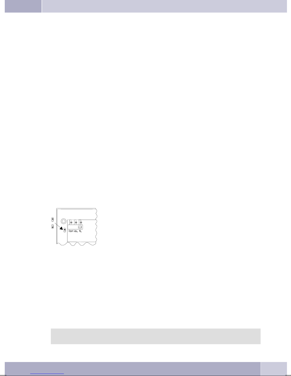
Emergencyoperation isnotconfiguredasa factorydefaultfeature. Aslideswitch islocatedonthebottom of
the system telephone that can be used for configuring emergency operation.
To configurethe emergencyoperation feature, slidethe switch on theleft side onthe bottom of thephone
down. To de-activate emergency operation, slide the switch back to the top position.
Attention: Before you move the emergency operation switch unplug the ISDN connector for
the system telephone. Use a non-metallic tool to move the switch.
Configuring emergency operation at a point-to-point (PtP) connection
Ifyou wishtoalso useyoursystem telephoneforemergency operationata PtPconnectionyou mustalsoac
tivatethis featureusingthe PCconfigurationforyoursystem telephone. Youcan usetheconfiguration pro
gram to set emergency operation at a PtP connection.
Making calls during emergency operation at a point-to-multipoint connection
The systemtelephone begins emergencyoperation whenpower supplyfor the PABXsystem and theNT is
lost.Emergency operation,followedbyatelephone symbolisthenshown inthesystem telephonedisplay.
Ifthe 230VACpower supplyisrestoredduring anongoingcall, allnormal,configuredfunctions areavaila
ble againonly afteryou hangup the handset. If the230V~ power supplyis restored whenthe handsetis in
the cradle,the emergencyoperation displayis replacedby thenormal displaywhenthe handsetis lifted,or
on the next call.
Making calls at emergency power supply mode on a point-to-point connection
During emergency power supply mode at a point-to-point connection, you will see the normaloperation
displays.
CS410
Thissystem telephoneisdesignedfor connectionto aninternal S0-port(4 wires)of an pabxsystem. If you
wish to connect the telephoneto an internal Up0-port, be sure to install the internal Up0/S0-module into
the telephone or use the external Up0/S0-converter.
-
-
-
CS410-U
Thissystem telephoneisdesignedfor connectionto aninternal Up0-port(2 wires)of an pabxsystem. The
internal Up0/S0-module or the external Up0/S0-converter is then no longer required.
elmeg IP-S400
Connectthis systemtelephonetothecorresponding LANport(or network)ofthePABX systemusinga Cat.
5cable. Thesystemtelephoneisequipped withaPC outputthatcan beusedto connectotherIPterminal de
vices.
Setting up/ Configuring the system telephone
On the system telephoneitself you can only carry out alimited configuration of thesupported features. A
fullconfiguration isonlypossible withanelmeg telephonesystemusingthe professionalWINtool configu
rator via the corresponding system telephone interface.
2
-
-
Page 12

System-telephone extension modules
Up0/S0-module (CS410 only)
Install theUp0/S0-module into your telephoneif you wishto connect thephone to a Up0-portof a
•
pabx.TheexternalUp0/S0-converter isthennolongerrequired.
Answering machine module (only CS410, CS410-U)
Thismoduleprovidesyour telephonewithamulti-functiondigitalansweringmachine.
•
FOREXAMPLE.: Separateprogramming foreachMSN extensionnumber, time-controlfeaturefor
voice announcement related to specific MSN extension numbers, automatic notification with
newlyrecordedcalls, recordingof dictations,logging ofcalls, remotepollingprotected byPIN.
Aspecialkey andLED areprovided foroperation ofthe answeringmachine.
Additional »T400« keyboard
Thisadditional keypadhas 20buttons withan insetLED, whichcan beused ontwo levelsas functi
•
onbuttons. The LEDisassigned tothe firstlevel. Another twoLEDs areprovidedfor indicatingad
ditionalinformation.
Up to three additional keypads can be connected (cascaded) to your telephone. A plug-in power
supply isrequired if youuse more thanone additional keypad. Use onlythe approved T400power
supplyunits availableasaccessory /serialnumber220872.5or T400-UK/serial number220873.3.
Description and installation
-
-
Additional »T400/2« keyboard
Thisadditional keypadhas 10buttons withan insetLED, whichcan beused ontwo levelsas functi-
•
onbuttons. The LEDisassigned tothe firstlevel. Another twoLEDs areprovidedfor indicatingadditionalinformation.
Safety notes
Mind the storage and operation temperatures for the device listed in the technical specifications.
•
Onlyconnectthe devicewhen thepermissible ambientoperating temperaturehas beenreached.
Please note that condensation on or in the unit may occur when moving from cold to warm sur-
•
roundings. Only removethe telephone from the packagewhen the permissibleambient operating
temperaturehasbeenreached.
Youshould notmake callsor connector disconnectany linesduring thunderstorms.
•
Onlyattachtheconnectingcords at theconnectionsprovided.
•
Make surephonecablesare installedina safemannerto preventtripping.
•
Avoidthefollowing:
•
Directsunlight
Sourcesof heat(for exampleradiators)
Electronicdevices(for examplestereocomponents,officeequipmentormicrowavedevices)
Ingressofmoistureorliquids
Aggressivefluids orvapors
Dustyenvironment
Donotusetheunitinexcessivelyhumid roomsor hazardouslocations.
•
Onlyopenthose sectionsofthedevicespecifiedinthe assembly/ operatinginstructions.
•
Donottouchplugconnectorswithpointed, metal,or moistobjects.
•
If you do not permanently mount the device or any accessories, be sure to place it/them on a
•
non-slipsurface.
Whenrequired, cleantheunit witha slightlymoistened cloth.
•
Onlyuseapproved accessories.
•
3
Page 13

Description and installation
Onlyterminals withSELVand/or whichcomply withETS300047 maybeconnectedto theunit.This
•
regulationisfulfilledwhenapproved terminaldevicesareusedas intended.
Plug-in power supply
Useonlyapproved powerplug-inunits(DSA-0101F-05 UPor L15D52 ABDDLAWO).
•
Donotusepowerplug-inunitswithvisibledefects ordamage(fissures,cracks, etc.)
•
Elektrostatic charges (protection against electrostatic charges)
The telephone issupplied with enhanced ESD protection againstthe effects of electrostaticdischarge that
exceeds theprotection levelcited in theapproval specification. Elevated ESD levelsshould neverthelessbe
avoided to thegreatest possible extent. In some cases, electrostatic dischargelevels can farexceed the ap
proval limitsor theresistance levelsalready implementedin yourtelephones. Eliminate thecauses orcon
ditions that promote theseelevated ESD levels, such as insufficienthumidity or carpeting. The telephone
manufacturer does not assume any liability for damage caused under such circumstances.
Unpacking and placing the telephone
Unpacking
Systemtelephone
•
Handsetwithhandsetconnectingcord
•
2feet
•
1ISDN connectingcord, approx.6 m(not withIP-S400)
•
Cat.5 connectingcord, approx.2 m(only withIP-S400)
•
PC-Connectioncable/USBcord ,approx. 3m (notwith CS400and IP-S400)
•
PC-audio cable,3.5 mmstereo jack,approx. 2,5m long(not with CS400 andIP-S400)
•
Adapter cordfor headsetwith a4 pinconnecting cord(8pin/4 pin)
•
Cableholder(self-adhesiveafterremovingthefilm) (notwith CS400)
•
Operatinginstructions andlabelsforfunctionkeys
•
Supplementwithtelephone safetyinstructions
WIN-ToolsCD-ROM with:
•
ProfessionalConfigurator,telephonedirectory-, download-and soundmanager,
TAPI-,USB-,CAPI- andNDISWAN driver,Adobe AcrobatReader,
Operatinginstructions andAdobeAcrobatfilefortheprintingofindividuallabels
-
-
Placing the telephone
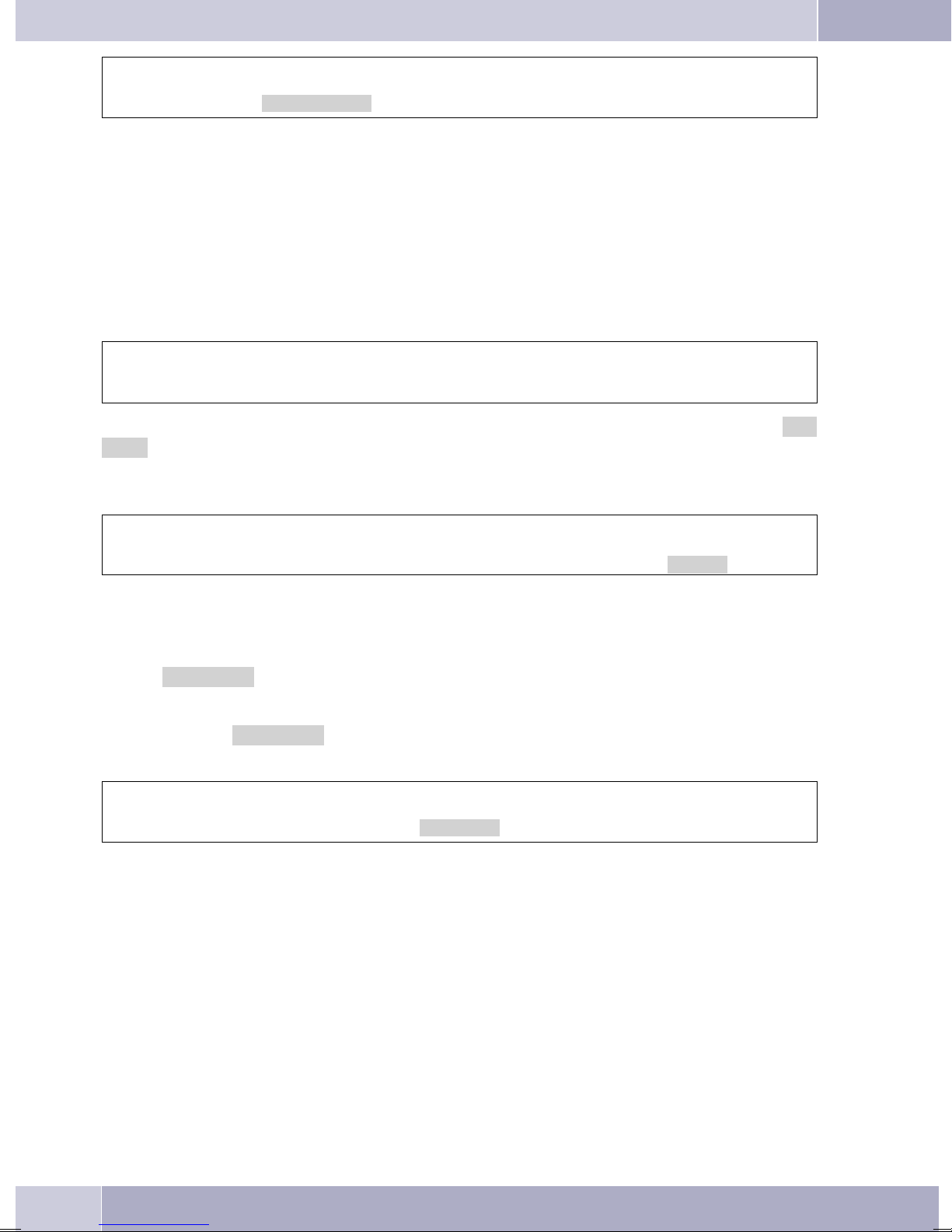
Beforeinstallingthetelephoneyou mustmount therear feetfor thetelephone atthe positions(6) shownin
figure 1.
Pleasenote thatthefeetofyour telephonemayleave marksonsensitivesurfaces,such asfurniture. The ma
nufacturer of the telephone is not liable for any such damage. Therefore, use appropriate non-skidding
pads under the phone.
Cleaning the telephone
The ISDN system telephone has been manufactured for normal, everyday use. When required, clean the
ISDN systemtelephone witha slightly moistenedcloth, orwith ananti-static cloth. Never use a solventto
cleanthe phone!Neveruseadry cloth;electrostaticcharges coulddamagethe electronicsinthe system. Itis
essential that no liquids penetrate into the inside of the ISDN system telephone, as this could destroy the
phone.
4
-
Page 14
Description and installation
Connecting the telephone (connecting and handset cords)
Pleaseconnect theISDNcableand thehandsetcable. Otherwiseyouwillnot beableto operatethephone.
2
6
4
5
5
4
4
3
6
7
1
Figure 1
Connecting the handset connecting cord
Connectthe handsetcord(1) asshowninfigure 1. Laythe handsetcordin thecordgroove (4)andlockitbelow the two cord retainers (5).
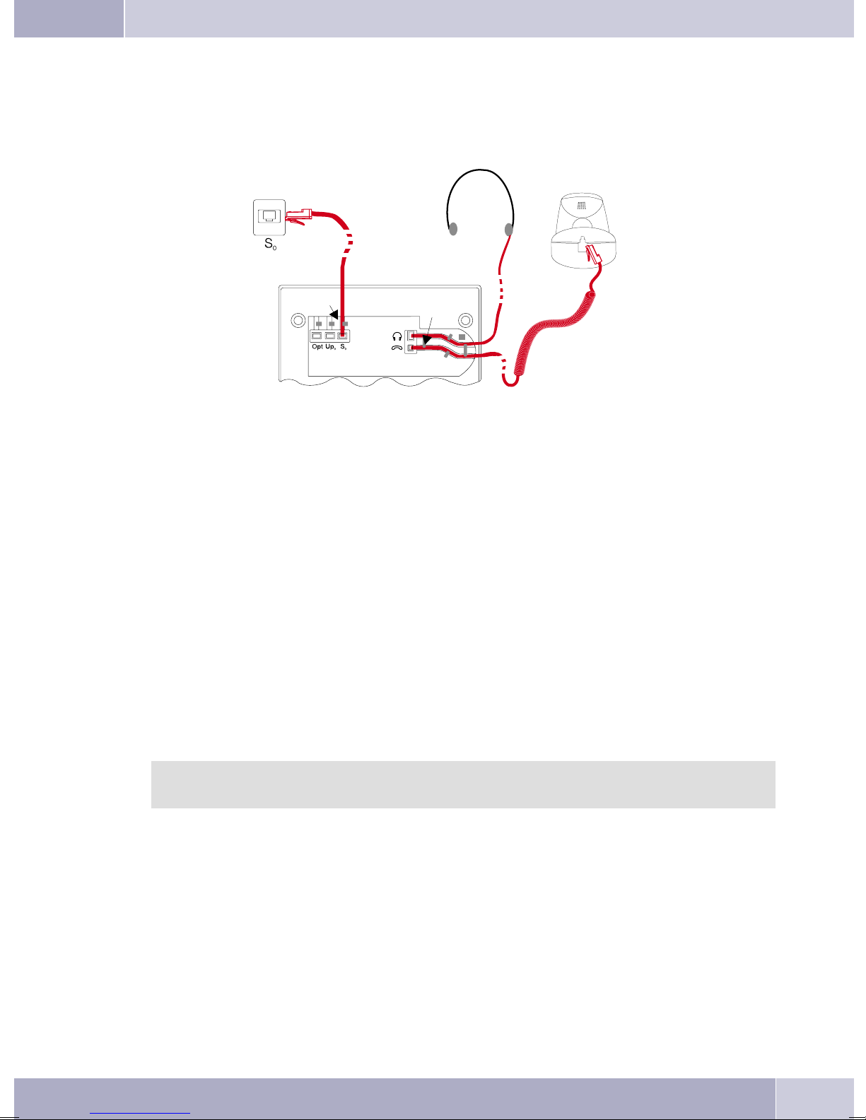
Connecting the connecting cord
Connection to the S0 (CS410, CS400)
Connect theISDN cord (2) asshown infigure 1 (S0-connector). Ensure that thelonger ISDN connectoris
pluggedinto theISDNjack andtheshorter ISDNconnectorinto theISDNsocket onthetelephone. Thenlay
the ISDN cord in the cord groove (4) and lock it below the two cord retainers (5).
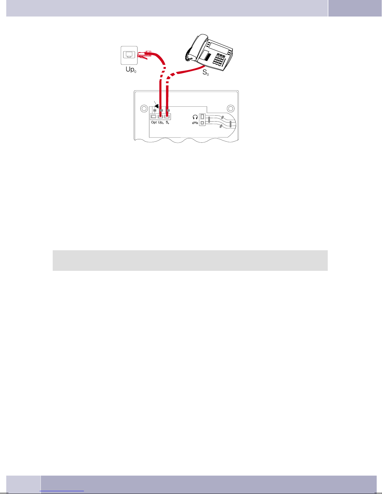
Connection to the Up0 (CS400,CS410 with Up410/S0-module or CS0-U)
Connect the ISDN cable (1) as shown in figure 2 (Up0-socket). Ensure that the longer ISDN connector is
pluggedinto theISDNjack andtheshorter ISDNconnectorinto theISDNsocket onthetelephone. Thenlay
the ISDN cord in the cord groove (2) and lock it below the two cord retainers (3).
CS410 telephones equippedwith a Up0/S0 moduleor CS410-U phones may not beconnected
through the S0-socket to an ISDN connection (e.g. internal ISDN port of the PABX).
Important notes for connecting the telephone to the Up0
Youcan connectafurther ISDNdevicewith anS0-port (forexamplean ISDNcardor aanothertele
•
phone) atthe S0jack of thetelephone. For eachadditional ISDN devicethis connection provides a
powerof1 watt.
-
5
Page 15
Description and installation
1
2
3
Figure 2
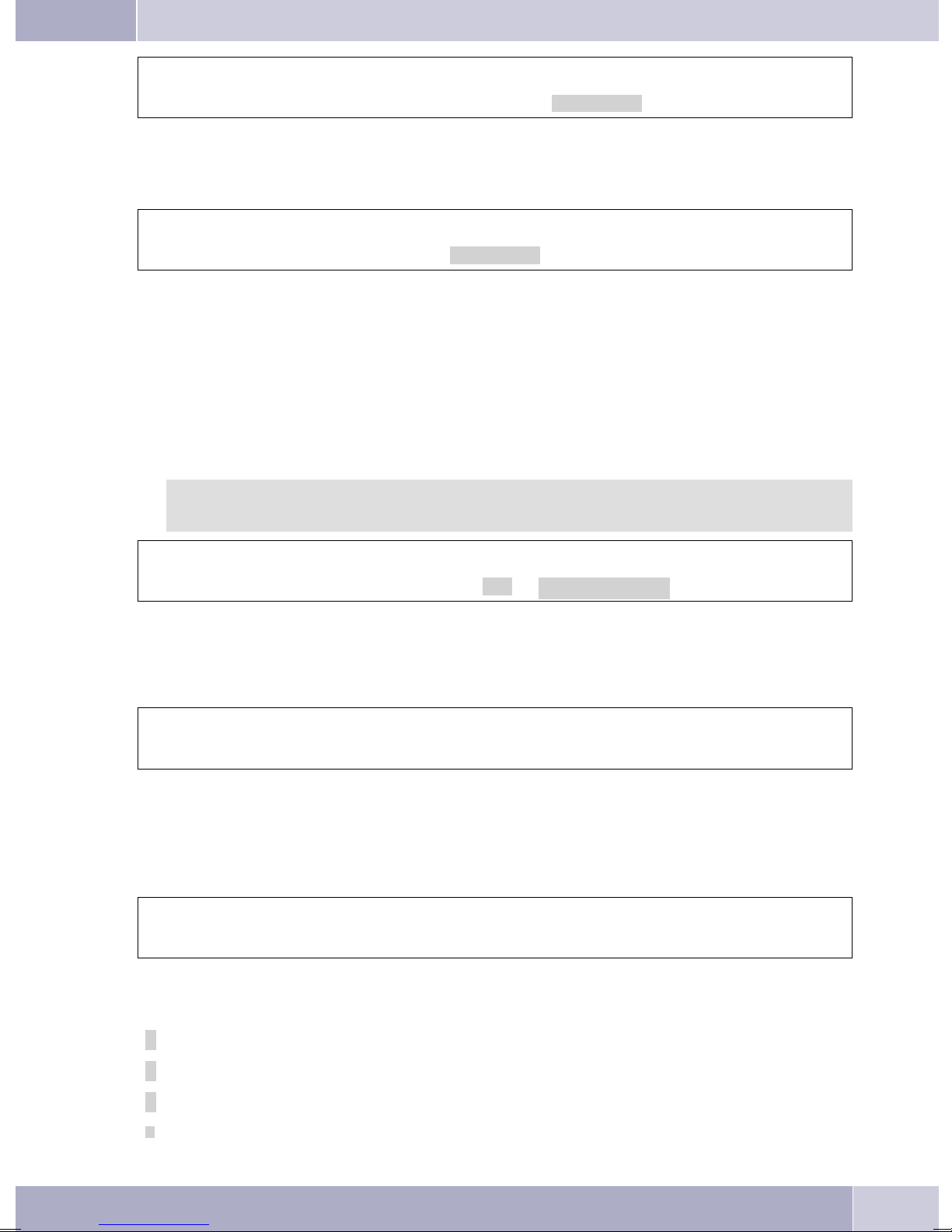
Connecting and configuring a headset (not included in the scope of supply)
Youcan connecta headsettoyourtelephone. Ask yourdealer whichheadsetmodels canbe usedorretrieve
the required information from the Internet.
The telephoneis equippedwith an 8-pinsocket for connectinga headset. Headsets witha DSHG-interface
(e.g. cordlessDECT-headsets)can beconnected tothe telephonerightaway. Specialaccessories arenot required for this. For the connection of standard headsets (connection cable of 4 pins, e.g. U10PS) use the
supplied adapter cord.
You canconnect / installthe optional AnsweringMachine moduleand a headsetwith a DSHG
port simultaneously to/in a system.
Connecting a headset
Connect the headsetas shown in figure 1 on page 5to the telephone’s dedicated headset socket. Then lay
the headset cord (3) in the cord groove (4) and lock it below the cord retainers (5).
If theheadset corddoes notfit inthe cordguide, attachthe self-adhesivecord holder suppliedwith thesys
tem to the bottom of your telephone (7). Then, route the headset cord under the cord holder.
-
6
Page 16
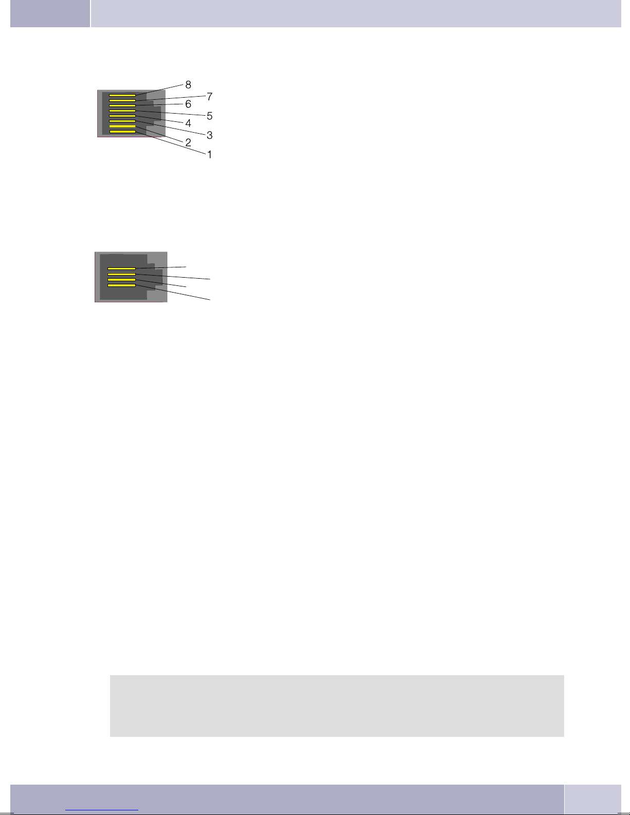
Assignment of the headset jack pins (CS410 / CS410-U)
3
8 - transmitter
7 - V+ (3.3V)
6 - Microphone - (Ground)
5 - Handset (3.3 V switchable via resistor)
4 - Handset (ground)
3 - Microphone +
2 - Ground
1 - receiver
Figure 3
Assignment of the headset jack pins (CS400 / CS400 /CS400xt)
4 - Microphone - (Ground)
4
2
3 - Handset
2 - Handset (ground)
1 - Microphone +
1
Description and installation
Figure 4
Further settings when using a headset
You canuse thehandset orthe headsetfor makingcalls. With headsetoperation, thefollowing settingsare
required or possible:
Whenconfiguring yourtelephone,program oneofthe functionkeysfor headsetoperation(headset
•
button,seepage54).
You can use theheadset connected to your system automat icallyfor certain actions on the phone
•
(seepage70).
Ifa specialsupport featureisstoredin yourtelephone fortheheadset yourare using,setyour phone
•
forthat headsetmodel (seepage59).
Forexample, theLED inthemicrophone extensionfor»Firefly F142N« fromPlantronicscan beac
tivated bythetelephone.
If youwould liketo usethe auto-answerfeature withyour headset, set thetime afterwhich acall is
•
answered(see page70).Whenconfiguringyour telephone,youshould programafunctionkeyto be
usedfor activatingor deactivatingthe auto-answerfeature.
If youhave configuredyour phone for automaticheadset use, you canpoll the answeringmachine
•
usingthe headset.
-
Connecting the telephone to a PC
Connecting the PC connection cable (USB)
Use theUSB cordsupplied withthe systemto connectthe telephoneto thePC, orto thehub. If
youuse adifferentUSB cord,ensurethatthe distancebetweenthe telephoneandthe PC,orbet
weenthe telephoneandthe hub,doesnot exceedfivemeters,depending onthetype ofcord you
are using.
-
7
Page 17
Description and installation
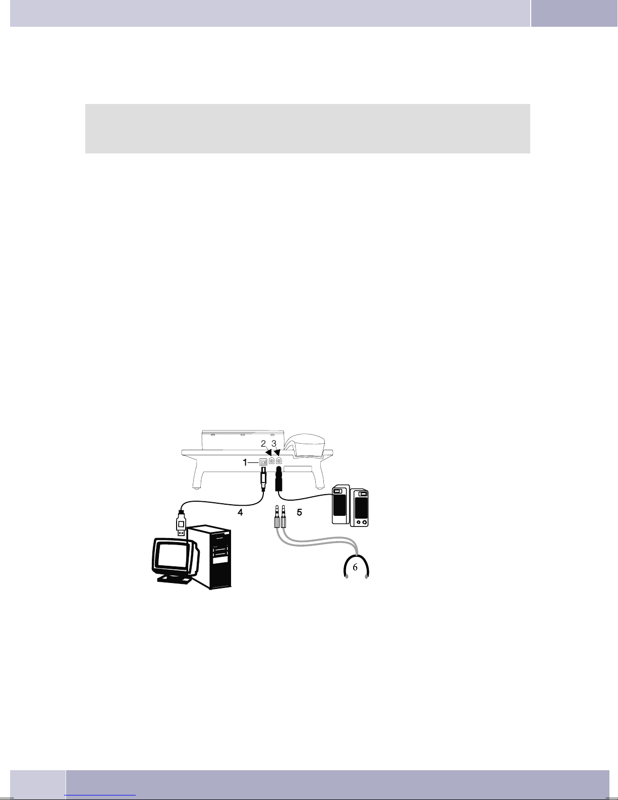
Connectthe USBcord (4)as shownin figure5(PC-socket). PlugtheUSB connector(type A)into thecorre
spondingsocket ofyourPC andtheUSB connector(typeB) intotheUSB socketonthe backofthe telephone
(1). The telephoneis automaticallydetected bythe PC,provided that both devices(telephone and PC) are
switched on.
Installat ionof a devicedriver is startedautomatically the firsttime you connectthe telephone
to thePC. Insert theWIN-Tools CD-ROMsupplied with thetelephone andfollow the instruc
tions displayed on the screen.
You willneed a hub(USB distributor)if you planto useseveral USB terminaldevices atyour PC. Connect
thehubto theUSBport ofthe PC.You canthen connectother USBterminal devices,including thetelepho
ne to the hub.
CS 410, CS 410-U connecting the audio cable (Audio in / Audio Out)
Thetelephone isequipped withan input(2)andanoutput (3)for audiosignals. Both theseports havea 3.5
mmstereo socket.Whenusing theoptional answeringmachine module,you canconnect thetelephone via
these ports to the PC sound card in order to upload announcements into the phone or save recorded
messages on the PC.
Youcan alsouse specifictelephonefeatures withthe Audio-Outoutput(see page64). Connectthespeakers
(5) with a 3. 5 mm stereo jack to the telephone’s Audio-Out (3) output, as shown in figure 5.
-
-
-
IP-S400 Audio in / Audio out
The telephone isequipped with an input (2) andan output (3) for audio signals.These ports are provided
for headsets(6). Thejacks are linked tothe correspondingports for the headsetjacks on the bottomof the
telephones.
Figure 5
elmeg IP-S400 at the Ethernet-port
The IP-S400system phonecan bepowered throughthe Ethernetport as defined inIEEE Std 802.3af-2003
(PoE),with powerbeingsuppliedvia Ethernetfrom thehubor switch.At theport, »AlternativeA«and »Al
8
-
Page 18
Description and installation
ternative B«, as defined by IEEE Std 802.3af-2003, and »Power classification 1« (up to 4 W) is supported.
The PoE port is not polarity sensitive.
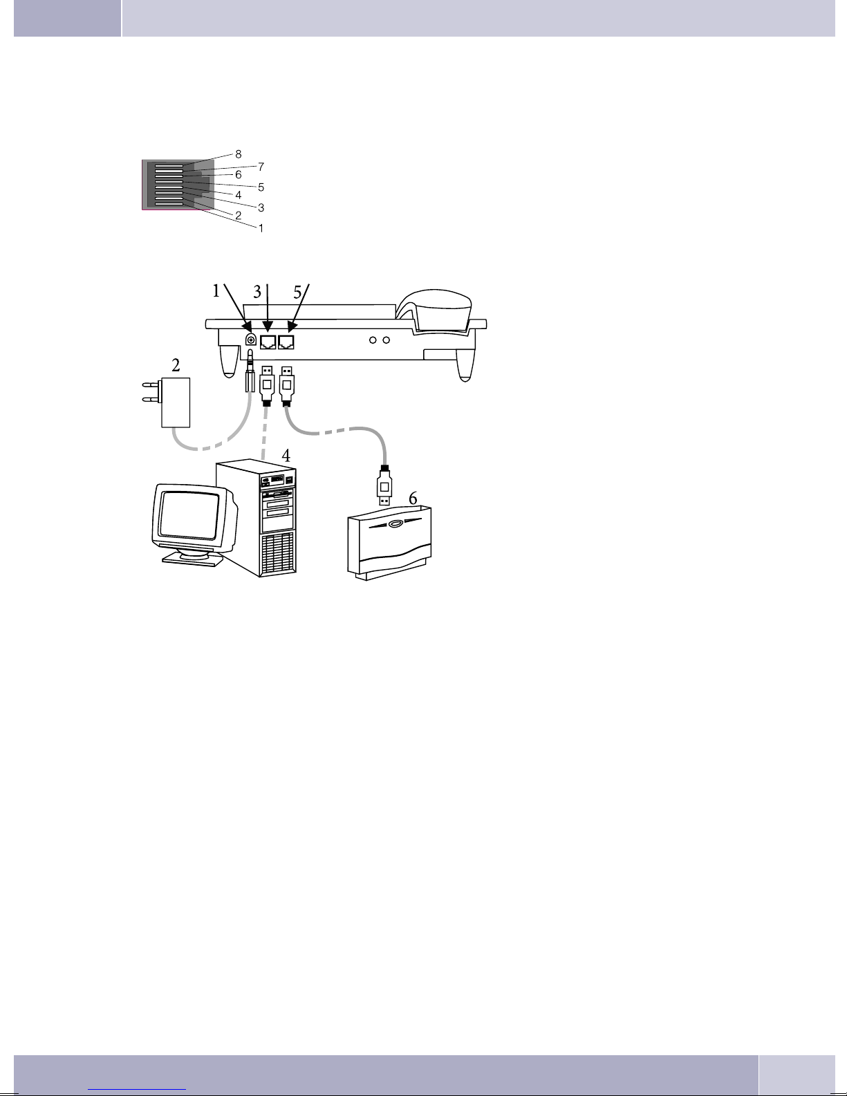
PIN assignment for PoE
PIN 1 = Transmit Data + / PIN 2 = Transmit Data PIN 3 = Receive Data + / PIN 6 = Receive Data PIN 4 / PIN 5 connected = power supply
PIN 7 / PIN 8 connected = power supply
Figure 6
1
2
3
4
5
6
Connection for plug-in power
-
supply unit
Plug-in power supply unit
-
Ethernet PC-Connection
-
PC or other IP-telephone
-
Ethernet-port of the pabx
-
elmeg pbx
-
Connecting to and operating the system telephone at the pabx system (basic function including
DHCP)
Consult theinstallation instructionsfor thePABX systemto determinewhich portcan beused forconnec
ting the IP-S400. Connect this port with the Ethernet PABX port on the system telephone.
•
ConfigureyourPABXsystemfor usewithIPsystemtelephones.
•
Definethe MSNsfortheIPsystemtelephoneswithinthe PABXsystem.
•
Switch onthe power (plug-in powersupply unit) to theIP system telephoneand wait until thetele
phonehasbeeninitialized.
OncetheIPsystem telephonehasbeeninitialized youwillberequestedto selectthelanguagein thedisplay.
-
-
9
Page 19

Description and installation
Selectthedisplay language.
•
Press the buttons to view the available langua
ges.
EnteroneoftheMSNs thathas beeninputto thePABXsystem(intheexampleshown here,12) .
•
Confirm your entry by pressing
If no PIN has been entered in the system con
figuration, press button
again after being requested to do so.
O
• Swtich toUse DHCP.
O
and button
. Programm dial number
O
-
Italiano
Deutsch
Français
MSN-1>12
-
MSN-1>
Which language?
Español
®English
Nederlands
IPS login PIN for sys
server
Select »on«. Use automatic IP
adress setting
off
on®
• The telephoneand PABXsystem aresynchronized.
Ifthere isnoconnectiontothe PABXsystem(no LANlink,or thetelephonehasnotbeen logged
in),the symboll»©-----/ /----‰ «will beshowninthedisplay insteadofthe time.
You can now use the IP system telephone at the ISDN or UP0 port.
You find a complete description of the configuration on page 84.
Changing the label
The label panels for the function keys are included on a separate sheet enclosed in the operating instruc
tions. Cut out the label you wish to use.
To changethe label panel,press the flexiblecover togetherbetween your indexfinger and thumband lift it
out. The label panel can now be changed.
Youcan fillinthelabel foryourtelephonewith yourowninformationand thenprintitout usingtheProfes
sional Configurator. Also available on theWIN-Tools CD-ROM is an Adobe Acrobatfile containing tem
plates that you can also fill in and print out.
-
-
-
10
Page 20

Description and installation
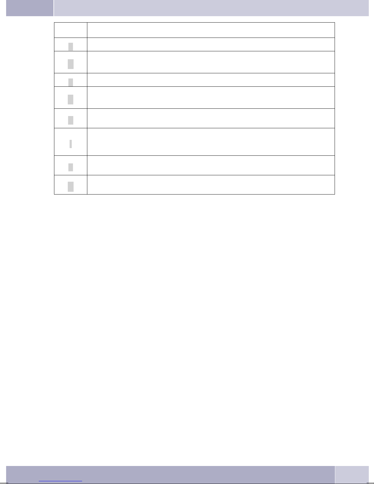
Pictographs
The pictographs (symbols) described below have been used in these operating instructions to illustrate
some procedures for setting and using the telephone.
b Liftup thehandsetorstart prepareddialing.
a Replacehandset.Thetelephoneis idle.
l Acall issignaled.Theringer melodysounds.
g Youare conductingacall.
d Athree-party conferencecallisinitiated.
q Youhear thepositiveornegative acknowledgementsignal.
t Selectthe callnumber,code, character ortext.
X Thissymbolpromptsyou toselectacertaindigitor character.
09
Presstheappropriatebutton onthepush-buttonset.
*#
Setting the display language
You can select the language of your display.
Begin as follows:
a
<>
s
Press the arrow buttons to view the available
languages.
Press the softkey adjacent to the desired
language. The display switches to the chan
ged language immediately.
Msss
Configuration Display Language
Which language?
Italiano
Español
Deutsch
-
Franªais
English
Nederlands
11
Page 21
Description and installation
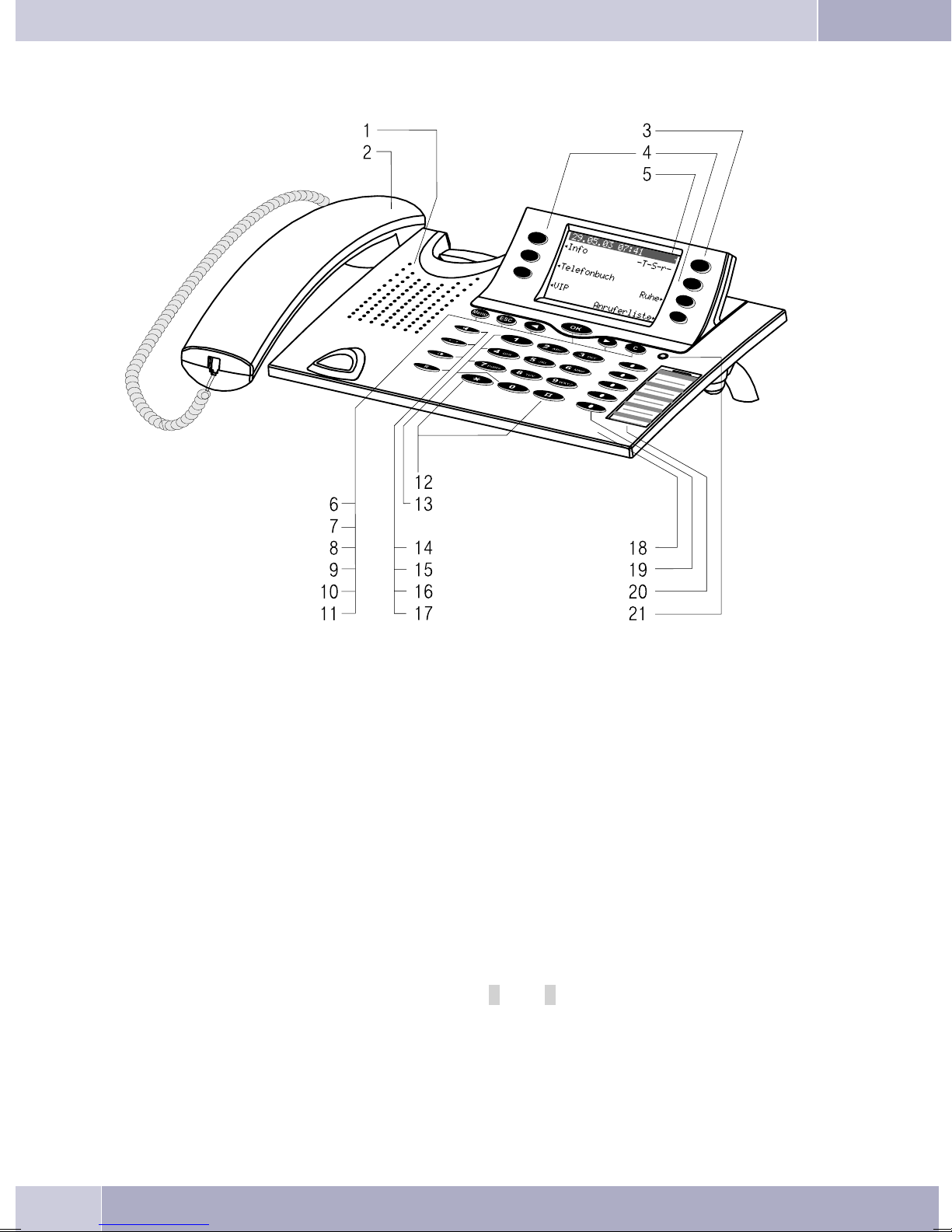
Telephone display and buttons
Figure 7
1 Speaker
2 Handsetwithconnecting cord
3 Answering machinebutton on thetelephone (optional module). With the CS400,thepabx
menuwillbe loaded.
4 6Softkeys
5 Seven-linebacklit display
6 Menukey: Thiskey opensthe programmingmenu. If youare alreadylocated ina menuand
thenpressthekey,eithermenu-specificfunctionsareshown,oryouaremovedback onepro
grammingstep.
7 ESCkey:PressingtheEscbuttonduringprogrammingreturnsthetelephonetoitsidlestatus.
8 / 10
9 OKbutton:Pressingthisbutton confirmsanentryorstores asettinginthe telephone.
11 Ckey:Pressthisbuttontomovebackonemenustepinthemenu. Ifyouarecurrentlyinthein
»left«/»right«arrowbuttons: Thearrows»{«and»}«intherightcorneronthetoplineofthe
display indicate that you can call up further functions on the lower lines using the arrow
buttons.
putmode, thisbuttoncanbe usedtodeleteindividualcharacters.
-
-
12
Page 22

Description and installation
12 Asteriskkey/hashkey
13 Dialbuttons
14 Openlistening/ hands-freebutton
15 Endingacall
16 Redialbutton
17 Inquiriybutton
18 Microphone
19 Eachbuttonhasaninsettwo-colorLED(level1-red/level2-yellow). TheseLEDscanbeused
toindicate certainfunctions.
CS410:TheLEDs forthetwobottomkeysof(levels 1and2)have twocolors.
CS410-U:The LEDsofallkeys havetwocolors(levels1 and2).
IP-S290:TheLEDsof allkeyshaveonecolor (level1).
20 Labelpanel forfunctionkeys
21 Status-LED,CallsignalingLED,receivedUUS andSMSmessagesandMWI(red) andanswe
ringmachine (yellow).Itispossible toconfigure thedesiredfunctional displayfor messages
andcalls.
Telephone display
Date
09.03.05 07:00
™Info -D-I-q-
™Tel. Drctry
™VIP
Caller list
Quiet
‰
‰
1
2 Time
3 21 characters per line
4 Arrow: Further menu items accessi-
ble by using the arrow keys.
Figure 8
5 Answering machine button on the
telephone (optional module)
6 Arrow: Indicationof thesoftkey that
can be used in the current menu.
A checkmark »®« following a display text indicates that this feature is active.
The telephone is equippedwith a seven-line backlit display. Backlighting is automatically switched on or
off.
After connecting the system tothe internal ISDN connection ofyour PABX system, the date andthe time
are shown on the display. The date and time are imported automatically from the pabx system. The text
displayed for a function isalways located next to the corresponding softkey. When you press the softkey,
the nextlevel isdisplayed. If notall information fitinto thescreen, thiswill beindicated by»««or»««. To
have the other characters displayed, press the R-button first and then the corresponding arrow button.
-
Various telephone display shots are illustrated in this operator’s manual to helpexplain the different set
tingsand useofthesystem. A wavylineat thetopor bottomofanillustrationindicates thatnotall ofthe7 li
nes of that particular display are shown (only pertinent lines shown).
-
-
13
Page 23

Description and installation
Special feature for displaying lists in the display
Severalentriesareshowninthe displayasalistfor certainsettingsorwhenusingthe phone. Theselists are
required for telephone directory or VIP memory programmings for example.
<> The activeentry (the oneyou haveselected) is
highlighted. Use the menu or the OK button
to display further features or select the high
lighted entry.
Special feature for changing existing entries
You have various options available for changing existing entries (for example names or numbers).
Example 1:
You may wantto change thetelephone numberof an entry, becausethat subscriber has movedto another
place.
When youuse the push-buttonset to enterthe first digitof the newnumber theexisting number isdeleted
completely. Enter the other digits of the new number.
Example 2:
You wishto change partsof a namein a telephonedirectory listing, becausethe name haschanged (e. g.in
the case of marriage).
Usethe arrowbuttons tospecify thestorage positionfor thatentry. Youcanoverwriteanexistingsurname
right away or delete it with the C-button and then enter the new name.
VIP digit to select {}
V0: 0123456
-
V1: TONY
V2:
¬¬¬¬¬¬¬¬¬¬¬¬¬¬¬¬¬¬¬¬¬¬¬¬¬¬
14
Page 24
Description and installation
Key assignments for entering texts
The assignments for the keypad for entering letters, digits and special characters are as follows:
Button Press
Button 1234567
1
2
3
4
5
6
7
8
9
*
#
1
ABc 2ÄÅÆ
DEF3
GHI 4
JKL5
MNO 6 ÖØ
PQRS 7ß$
TUV8Ü
WXY Z 9 ¥
*
#
0 Severalspecialcharactersareassignedtothebutton»!«,»+«,»-«,»=«,»(«,»)«,»@«,»$«,. .
Whenyou pressthe 0 key thefirst timeaspace isinserted. When youpress thiskey asecondtimeseveral
special characters are shown in the display. Press the appropriate key to select the corresponding special
characters
Input mode for entering letters
You ha«.
»ABC« Thenextletter thatyouenterisshownasa capital,allothersassmall caseletters.
»ABC« Everyletterthatyouenter isshownascapitals.
Call signaling
Call signalingis effected usingthe ringingtone that hasbeen set forthe dialed number(MSN) in eachtele
phone.
If youare usingthe telephoneat aninternal ISDNconnection ofcertain elmegPABX systems,you canpro
gram special ringing melodies for internal and external calls.
1 … 9. If you wish to view further special characters, press the 0 key.
Example:»Dean, James«.
Example:»Dean, James«.
Whenyou startentering texts,theinput modeis always»Abc«.Press theRecallflashbutton to
change the input mode. To insert a character while in »Abc« mode, press the C key.
-
-
15
Page 25

Description and installation
Function keys and LEDs
Youcan programthefivefunctionkeys ontwo levelswithdifferentfunctionsviathePCconfigurationpro
gram forthe telephone. Each key isequipped with anLED that isused to displaythe activefunction. Each
color is assigned to a particular level for the function key. (level 1 - red / level 2 - yellow).
Pressthe keytwotimestoreach thesecondlevelfor thefunctionkeys. Thismustbedoneat ashortinterval.
LED call signaling and answering machine
flashes red: Incomingcalls
lit yellow: Answeringmachineswitchedon
flashes yellow: Newmessagesrecordedbythe answeringmachine
Acknowledegement signals
Entries or settings you make at your telephone are sometimes confirmed by acknowledgement signals.
Positive acknowledgement signal (1 long tone):
The positive acknowledgement signal indicates that your input has been accepted and stored by the
telephone.
Negative acknowledgement signal (3 short beeps):
You willhear thenegative acknowledgementsignal whenyour inputhas notbeen accepted bythe telephone, or when invalid input has been made.
-
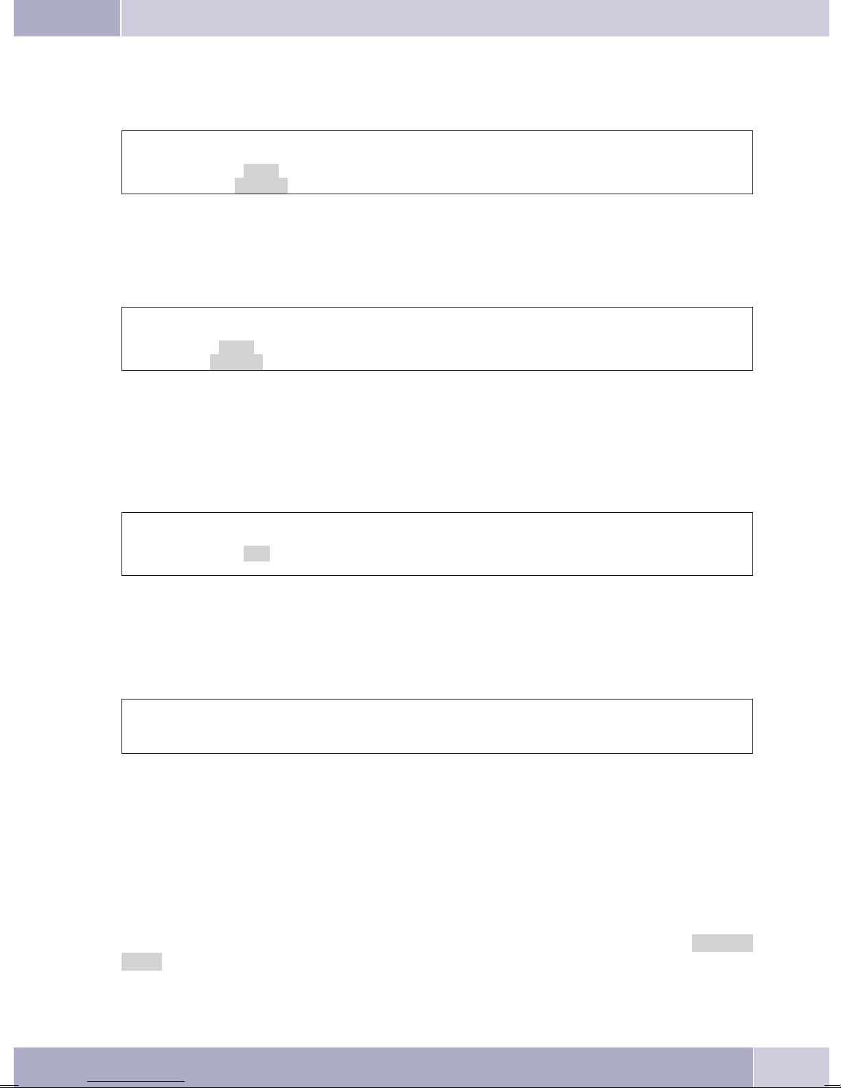
Displays for programmed features
s When the telephone is in the idle state, addi-
tional information about functions that have
beenconfiguredareshown on»Info«lineof
the display. In this example: »-t-S-R-«.
Press the softkey »Info« if you wish to get
more information about the configured
functions.
<> If you have programmed several features,
press the arrow buttons to view the various
settings.
29.05.06 07:21
Info -T-S-r-
Tel. drctry
Idle
VIP
Caller list
ªªªªªªªªªªªªªªªªªªªªª
Inhibit/Menu access:
Guard for modification
16
Page 26
Displays Configured function
»D«
Active appointment reminder set.
Description and installation
»I«
»q«
»Q«
»U«
»i«
»I«
»%«
Dialing control or Call filter active,
Access to telephone menus is protected.
Function »Silent signalling« (notice tone only) active.
Function »Silent signalling« (all calls) active.
(All call signals are switched off)
Call forwarding active.
Informationen on programmed function keys
FOR EXAMPLE.: Message enabled / inhibited.
Informationen through Messages (MWI) For example. auf Ihrer t-Netbox
Answeringmachine,timecontrol, notificationorremoteoperation(option module)active.
17
Page 27

Making Calls
Making Calls
Starting a call
Dial number - no correction possible
btg
Dial number
Dial call number - correction possible
atbg
Dial number
Tochangethe numberor tocorrect awrong entry,select thewrongfigurewiththe arrowbuttons andpress
C to delete it. Now enter the correct number.
If youwish to conductthe callusing the handset,just lift itup after dialingthe number. Any timeduring a
call you can switch back and forth between hands-free calling, speaker function and use of the handset.
Afteryou havedialedthe numberyoucan alsopressthespeakerecall flashbuttonto havethenumber dialed
and to use hands-free calling.
If a callcan not be put through(e. g. number isinhibited via thedial ranges control, or theaccount for the
number/MSNis empty),a correspondingmessage willappearin thedisplay. e.g.:»Inhibit. : dial
number«, when the dialing filter is active.
When you lift the handset and there is still no connection set up, you can pick up a waiting call using the
softkey »pick up«without replacingthe handset again.You are notifiedof thecall inadvance by abrief
message. When youconfigure a connectionkey or a macro keyyou can pick up a call immediatelyjust by
pressing that key.
Other options for dialing without lifting the handset
Theoption ofdialing withoutlifting thehandset andof correctingor addingto anumber alsoexists during
dialing:
fromthelastnumberredialing memory(see page21).
•
fromthecaller/memolist(seepage35).
•
fromthetelephonedirectory (seepage32).
•
fromtheVIPmemory(see page34).
•
withthefunction keys(seepage 66).
•
viaCTI(TAPI) features (seepage 97).
•
Ifyou areusing oneoftheseoptions, youcan makefurther entriespriortoinitiating thecall. Youcan define
which number (MSN), if any, is to be transmitted to the party being called. You can use the Professional
Systel-Configurator to set which function is to be assigned directly to the softkey »Telephone directory«:
»Local« or »PABX«. You can reach the second function by pressing the R (Recall flash) key.
18
Page 28
Dialing from the pabx telephone directory
Making Calls
When youuse thistelephone witha system telephony supportingpabx system,you can dialfrom the tele
phone directory of the pabx.
a
Dialing from the telephone directory
You can store up to 250 names and numbers in the telephone directory. To select a name, you can page
through the directory using the arrow buttons, or enter the specific first letter(s) of the name using the
push-button set.
For informationon how toprogram and configurethe telephonedirectory, please referto page 32 ofthese
operating instructions.
Dialing from the VIP memory
Youcan programVIP numbersforeachof theten dialbuttons1… 0including aname(20 charactersmax.)
and a telephone number (26 digits max.).
Rs
drctry
a
s
Tel.
drctry
t
Tel.
Enter first letter Select
t
Enter first letter Select
O<>O
entry
O<>O
entry
bg
bg
-
a
For information on how to program VIP entries, please refer to page 34 of these operating instructions.
Direct dial-in using function keys
Direct dialing isinitiated using the direct dialingkeys. Each of the fivekeys can be programmed withtwo
functions or direct dialing numbers.
a
Use the function keys to select the desired number.
Ifyou wishto diala numberfrom thesecondlevel,press thecorresponding keytwo times. This mustbe ex
ecuted at a short interval.
You can program thedirect dialing / functionkeys via the PCconfiguration program for thetelephone or
during extended configuration.
from Dialing from the caller/memo list
s<>
VIP
Select VIP
destination
Z
Press the function key
or
tbg
Select VIP
destination
bg
-
Thephone hasa combinedcaller andmemolist. Amaximumof 30entries (calls,memos, SMSmessages or
UUS1- messages) are stored in this list. Entries in the caller or memo list are indicated by the »Caller
list« softkey.
19
Page 29
Making Calls
a
Formore informationaboutthecaller/memolist, pleaserefertopage35 oftheseoperatinginstructions.
s<>
Caller list
Select entry
bg
Accepting / rejecting a call
In itsinitial statethe telephonewill acceptall calls, regardlessof the selectedMSN. If twocalls aresignaled
simultaneouslythe firstoneisaccepted whenyouliftup thehandset. Thesecond callcan stillbesignaledy a
call waiting signal.
Thetelephone displayshowsthe caller’snumberorthe numberthecaller hasdialed (MSN-1…MSN-10, or
the assigned name).
albg
If you areunable, or do notwish to accept acall, you havethe option of rejectingthis call. Press the »re
ject« softkey and the call will be no longer be signaled at your telephone.
If you area member of ateam, then this callwill continue to besignaled at the phonesof your team. If the
call was signaled only at your phone, the caller will hear the busy signal when the call is rejected.
-
al
s
reject
Call Deflection
If you are unable, or do not wish to accept a call, you have the option of forwarding this call. Press the
softkey »transfer«,if youwish to forwardthis call directly toanother subscriber. The call number of
the forwarding target can be preset for each call number (msn) when configuring the telephone.
Afterpressingthe »transfer«softkey, youcan forwardthe callto thepreset callnumber orenter anew
call number.
al
transfer
s
t
Dial number
O
No number transmission (anonymous call)
You can block thedisplay of your telephone number atyour caller’s telephone if desired. You can set this
function specifically for the next call, or permanently (see page 50).
Suppressing calling line identification for the next call
During anexternal or internal call,you can prevent thenumber from beingtransmitted (displayed)to the
party you have called.
20
Page 30
Making Calls
at
Dial number
Whena callissignaled,youcan decidebeforeacceptingthecall whetheryournumberisto betransmittedto
the caller. If your phoneis the final destinationof call rerouting youcan use thisprocedure to prevent the
caller from seeing the final destination phone number (i. e. yours).
al
OMs
Concealed
s
Concealed
bg
bg
Starting a call with a fixed extension number (MSN)
You can conduct an internal or external call such that a defined number (MSN) is transferred from your
telephone tothe party youare calling. This numbermust have beenentered previously inyour telephone.
When you call, either number that is transmitted is shown in the second line of the display (»msn1...
msn-10«) or the name that you have assigned to this number (MSN).
Youcaninitiatedialingusing theset extensionnumber (MSN)as explainedin thefollowing,or youcan use
a programmed function key for this.
Use the WIN-Tools telephone directory manager to set up and configure an MSN extension
number to be used for outgoing calls.
at
Dial number
OMs s
MSN
MSN-1 … MSN-10
bg
Redialing
The previously dialed call number is stored in the redial memory.
ab
Extended last number redial
In the extended redialing function the telephone numbers of the last 20 calls, connections (calls) or text
messages are stored. You can view these by pressing the redial button or the arrow buttons and subse
quently have them redialed automatically.
a
The lastdialed numberis displayed. At theend of thesecond linethe statusof thisentry isindicated bythe
letters displayed there.
WWO
Select entry
W
g
bg
-
»v« Connection
»r« Call
»M« Mail(extensionnumbers,towhichSMS orUUS1messageswere sent)
»|« Callsconfiguredforautomatic redialing.
21
Page 31

Making Calls
no entry Youplaced acalltosomebodybutdidnot reachhim/her,or his/herlinewasbusy.
Deleting a telephone number from extended redialing or save as a memo
a
Press the softkey below »delete?«, to delete the displayed entry immediately. Press the »Memo?«
softkeyto writetheentry asamemo tothememo list. Theentrywillthen bedeletedfromthememo list.The
next telephone number is then displayed.
For an entry in the memo list, the softkey »Caller list« is shown on the display.
Importing numbers from extended redialing into the telephone directory
You can import a number that is present in the list for extended redialing into the telephone directory of
your phone (see page 32).
Begin as follows:
a
t
O
WWM s
Select entry
delete?
WWMs
Select entry
Enter the name.
In this example: »DEAN«.
Confirm your entry with OK.
Input telephone book
Name>Dean`
or
Tel. drctry
s
Memo?
In the redialing function the name displays
instead of the number.
Automatic redialing
If youplaced acall to asubscriber whosenumber isbusy orwho does notanswer, youcan thenactivate au
tomatic redialing which will call that same subscriber again after about 10 seconds.
atg
Dial number Subscriber busy
Afteraround 10seconds thehands-freecalling functionof yourphoneis activatedand thenumberis dialed
automatically. This is repeated for up to around 2 minutes.
Up to 20 call attemptsare made if thesubscriber can still not be reached. After 20 unsuccessful attempts,
automatic redialing will be cancelled. You will hear the negative acknowledgement signal in that case.
W
5/DEAN v
Tel. drctry
or
repeat request
s
Autom.
memo?
a
-
22
Page 32

Making Calls
If automatic redialing is active, the »Autom. repeat request« softkey is shown on
thedisplay. Press therightarrowbutton orthe »Continue« softkey,toreturnto thenormal
idle state display.
Suspending automatic redialing
You can suspendautomatic redialing that you havestarted any time using theappropriate procedure and
placea normalcall. To suspendautomatic redialing,press theopenlistening/hands-free buttonduring au
tomatic redialing.
After the call automatic redialing starts again.
Deactivating automatic redialing
You can deactivate automatic redialing at any time. There are no further call attempts.
To deactivate automatic redialing during the dialing process press ESC.
If you like to deactivate automatic redialing in the idle state of the phone, proceed as follows:
-
a
Autom. repeat request ok
ss
Microphone activation/deactivation, open listening and hands-free
calling
Mute on/off
The mutefunction allows youto switch offthe handset microphoneduring a normalcall, or thetelephone
microphoneduring handsfree calling. The subscriberyou arecalling willthenno longerbe ableto hearthe
conversationyouconduct withpersons inthe room(room inquiriy). However, youwillcontinueto beable
to hear the party on the phone.
g
Call duration and cost logging are continued even if the microphone has been muted.
Speaker function
The “Openlistening“ function canbe activatedwhen thereare other persons inthe room whowish to also
participatein thecall.You continuetotalkinto thehandsetwhile thisfunctionis active. You cansetthe vol
ume during the call as described on page 60.
Please inform theparty you are calling thatopen listening is activated. »|«indicates that open listening is
activated.
s
Mute speak
Room inquiriy
s
g
-
g
When youhang up thehandset while openlistening isactive, bothopen listening andthe call itselfare ter
minated.
LL
Begin open listening End open listening
g
-
23
Page 33

Making Calls
Hands Free Calling
The handset remains in its cradleduring hands free calling. Thebuilt-in microphone and the speaker are
activated. Any actions are carried out using the open listening / hands-free button only. You can switch
back to normal»handset« calls at anytime during hands freecalling by merely liftingup the handset. You
can also switch from normal »handset« calling to hands free calling when you hang up the handset after
pressing theopen listening /hands-free button. During hands-freecalling acousticsignals such asthe call
waiting signal are not transmitted.
Pleaseinform theparty youare callingthat hands-freecalling isactivated.»|« showsthat handsfreecalling
is activated.
a
L
Begin hands free calling Dial number End hands free calling
t
L
Headset use
Youcan connectaheadset toyourtelephone.Connect andconfigurethe headsetasdescribedonpage 6.
You can use the handset or the headset for making calls.
Activating and deactivating the headset
Forheadsetoperation, oneof thefunctions buttonsmust beconfiguredas aheadset key. The LEDassigned
to this key indicates, whether the headset in switched on or off (LED on or off).
a
Activating and deactivating open listening while using the headset
g
Call via headset Activate open liste
z
activate headset Dial number Call via headset Deactivate headset
L
-
ning
g
Call via headset and
open listening
tg
L
Deactivate open liste
ning
g
-
Call via headset Deactivate headset
z
z
Announcement
Themessage functionallows youtoestablish aconnection toadifferent telephone,without thisconnection
havingto beactivelyaccepted (pickingupthe handset,hands-free callingorloudspeaker). Thisisa simplex
(one-way) call in which only the subscriber that initiated the message will be heard.
As soonas atelephone acceptsthe message, the connectionis established. Fora messagecall, enter the in
ternal numberof theparty youwish tocall. You alsoonly needto enterthe internalnumberwithdirect ex
change line access. e.g. »22« instead of »*22«.
Whena messagecomes inforyourtelephone,the numberor thenameofthe partysending themessage ap
pears in the display. The message can be terminated at any time by pressing the ESC key.
Messages are accepted automatically by the phones being called byactivating the open listening function
when:
thephoneis idle.
•
messaging has been enabled for the pabx (control by means of the »Enabling intercom« function
•
key).
the»Silentsignalling« functionis notactivated.
•
24
-
-
-
Page 34

Making Calls
Messages canalso be receivedeven ifthe »Station guarding«function is active whenthe »Enablingmessa
ges« function key has been programmed and is activated.
You caninitiate amessage usingthe proceduredescribed below,or usinga programmedfunction key.You
can also initiate a message during an ongoing call (inquiry call) using the corresponding function key.
Youcan onlyutilize thisfunctionif themessaging featurehasbeen enabledinthepabx foryour
MSN extension number.
Begin as follows:
a
t Enter the telephone number, for which the
message isto be given,or select anentry from
the telephone directory.
g
L
As soon as a telephone accepts the message,
the connection is established.
Press the openlistening/hands-free button to
end a message.
Ms>s
Acoustic Message
| Message to
MSN-1
Tel. drctry
| Message 22
00.24 MSN-1
Display
memo
-
Intercom
The intercomfunction allowsyou toestablishan internalconnection toanother systemtelephone without
the called system telephone having to accept the call actively (lift up handset, hands free calling/activate
open listening). This is a call in which both parties can speak to one another.
As soonas the system telephonehas accepted theintercom call, theconnection is established.If oneof the
parties picks up the handset during an intercom call, the call becomes a standard type of call.
Foran intercomcall, entertheinternal numberofthe partyyou wishtocall. You alsoonly need
to enter the internal number with direct exchange line access. e.g. »22« instead of »*22«.
Whenan intercomcall comesin foryour systemtelephone, thenumber orthe nameofthecallingparty ap
pearsin thedisplay.The intercomcallcanbe terminatedatany timebypressingtheESC key. Intercomcalls
are accepted automatically by activating the »Hands- free« feature when:
thetelephoneis idle,
•
the intercom feature hasbeen enabled for thepabx (control by means of the »Enablingintercom«
•
functionkey).
the»Silentsignalling« functionis notactivated.
•
Intercomcallscanalsobereceived evenif the»Station guarding«function isactive whenthe»Enableinter
com calls« function key has been programmed and is activated.
-
-
You can initiate intercom calls using the following procedure, or using a programmed function key.
You canonly utilize thisfunction ifthe intercomfeature for systemtelephones has beenenab
led in the pabx for your MSN extension number.
-
25
Page 35

Making Calls
Begin as follows:
a
t Enter thetelephone number, forwhich thein
tercomfunction isto beactivated, or selectan
entry from the telephone directory.
g
L
The connection is set up when the telephone
has accepted the intercom function.
To end the intercomfunction, press the open
listening/hands-free key.
Ms>s
Acoustic Intercom
| Speak to
-
MSN-1
Tel. drctry
| Intercom 22
00.25 MSN-1
Display
memo
Automatic completion of call
Using theautomatic completion ofcall to busysubscriber feature, youcan reach asubscriber whose lineis
busy orwho is not nearhis or hertelephone. You arethen notifiedthat the subscriberfor whichrecall has
been configured can now be reached. You receive this information from the exchange office for external
call-backs and from the PABX system for internal call-backs.
The telephone display then indicates »Autom. callback«. This display alternates every 2 seconds
betweenthe numberornameof thedesiredparty. As soonasyou acceptthisinformation (bypickingupthe
handset, for example), the selected party is called automatically.
Automatical recall to busy subscriber (CCBS)
You hear thebusy signal whencalling the extension ofthe person you aretrying to reach. »Completion of
call tobusy subscriber«allows you to callthe extension as soonas the othersubscriber hangsup his or her
telephone.
Automatic completion of calls on no reply (CCNR)
When you call the desired number you always get a ringing signal, but the party is not near the phone or
does notanswer. Using thefunction»Completion ofcall onno reply«you canreach theparty immediately
when he/she ends a call, or lifts and then replaces his/her handset.
Programming completion of call to busy subscriber
btg
Dial number Subscriber busy or does
not answer
The »Clbckbusy« softkey is only displayed, when automatic completion ofcalls are possible with the
exchangeoffice orwith thepabx.Thefeatures »Recallto busysubscriber«or»Recall onno answer«mustbe
applied for at your service provider for external call-backs.
You canconfigure threecall-backs at atime. If you areusing anLCR procedure (e.g. theLCR procedureof
thephone), the»Completion ofcall tobusy subscriber«function iscarried outautomatically viayour stan
dard network service provider.
s
Clbckbusy
a
-
26
Page 36

Making Calls
Ifautomaticredialingisactive,the»Clbckbusy«softkey isshown onthe display. Pressthe
right arrow button or the »Continue« softkey, to return to the normal idle state display.
Viewing and clearing call-back calls
When thephone is inidle, any call-backcalls that are initiatedcan be viewedin the displayby pressing the
softkey »Clbckbusy«. Press this softkey to view the call-back calls. You can then view the individual
completioncalls usingthearrowkeys. If youwish todeletea callcompletion, selectthiscall usingthearrow
key and then press the menu key, followed by the »delete?« softkey.
All completions of call are automatically deleted after a predefined period. This time is set by the service
provider for external call-backs and by the PABX system for internal call-backs.
Ifthe ISDNtelephone isdisconnected fromthe ISDNnetwork, (forexample byunplugging the
ISDN connectorof the phoneor byswitching offor resetting thepabx), allrequested call com
pletions will be lost.
-
Parking a call (not with IP-S400)
Theparking functionallowsyouto interrupta callforupto threeminutes. Youcanthen unplugtheplug-in
connector foryour ISDN systemtelephone from theISDN jack andplug it inin adifferent room. You can
continue withthe previous callafter »unparking« it. Or youcan »unpark«the call ata different phoneand
continue your call there.
Parking is only possible whenonly one connection is currently active with your telephone. After you unpark the call, the number for the parked subscriber will no longer be shown.
A»parking code«(0.. ..99) isusedtoensurethat youarereturned totheproper callwhentwocallsare park-
ed. The default parking code is 55.
Ifyou parktwocalls onanISDNbusthis busisthendisabled forfurthercalls. Unparkingis possibleonly onthe buson whichthe callwas alsoparked. Parking isonly possiblewhen onlyone
connection is currently active with your telephone.
Park
g
Conversation
Unparking
a
s
park
t
Enter park code
>s
t
O
O
a
Disconnect and then
reconnect
bg
Tracing (MCID)(only via ISDN cord)
If you receive aprank or malicious call, you can arrange forthe number ofthe caller to besaved at the ex
change.
To enable this feature (Malicious call identification), it must first be applied for at your network service
provider.
unpark
Enter park code Conversation
-
27
Page 37

Making Calls
Identification of thecaller is effected in theexchange and the number storedthere with infor
mation on the number of the caller, the date and the time of the call.
You can use this feature in 2 situations.
Malicious call identification during ongoing call
You want to identify a cal
g
Call with subscriber
After the caller has hung up the handset
You wish to determine the caller,
g
Call with subscriber
You can initiate tracing only in the course of an ongoing call when you are conducting
hands-free calling using the telephone.
but he/she has already hung up the
ler.
handset.
-
>s
mcid
s
mcid
The telephone number
can then be established in
the exchange.
The telephone number can then be
established in the exchange.
-
a
a
Keypad and tone frequency dialing (DTMF dialing)
During anongoing callyou can takeadvantage ofother featuresusing keypadsequences orDTMF dialing.
Inthe telephoneconfiguration programyou canset whetherecallflash buttonpadsequences or DTMFdialing is to be possible in the initial status of the telephone. The display indicates which other functions
(keypad or DTMF) are possible.
»Keypad« softkey is displayed. DTMF sequences can be entered right away and keypad se-
quences only after you press this softkey.
»DTMF« softkey is displayed. keypadsequencescan beentered rightaway andDTMFequen-
ces only after you press this softkey.
Keypad andDTMF sequences canalso bestored forfunction keys, whichcan thenbe used du
ring a call.
Keypad
Usingthe Keypadfunction youcan manageservice or featuresin thePABX systemor in thenetwork ofthe
serviceprovider byenteringcharacter stringsanddigitsequences viathekeypad. Ask yournetworkservice
providerabout thisandconsult themanualforyour PABXtodetermine whether“Keypad“issupported.
g
Tone dialing (dtmf dialing)
Using tonefrequency dialing,you can transmitmultifrequency signals(DTMF signals)during anongoing
callinorder, forexample, topoll youranswering machineorfor usingmailsystems. If callwaiting isactive
for an ongoing connection, tone frequency suffix dialing can not be utilized.
s
keypad
t
Input of character strings and digit sequences
-
28
Page 38

Conducting calls with several subscribers
g
s
DTMF
t
Input of character strings and digit sequences
Conducting calls with several subscribers
Call waiting
If, duringan ongoingcall, asecond callcomes infor you, thesecond callis signaled when„Call waitingon“
is set (see page 68 ).
g
Call with subscriber 1
Youcan takeawaiting caller,rejectthe call,orswitch toadifferentsubscriber.You cannottransfer anycalls
if you already have four calls on your phone.
You can take a waiting caller, reject the call, or switch to a different subscriber. You can not
transfer any further calls if you already have four calls on your phone.
call waiting
(subscriber 2)
s
accept
g
Call with subscriber 2;
Subscriber 1 is put on hold
Inquiry Call
You have the option of establishingup to two other connections during an ongoingcall using the inquiry
callfunction.You canalso usethe MSNassignment key,a linekey oran extensionkey toinitiate aninquiry
connection.
g
Call with subscriber Subscriber 1 in hold condition Dial call number Call with subscriber 2
If you wish to set up further connections, proceed as described above.
Anactive connectioncan beterminated bypressing thekey forendinga call.You canreturn tothe callthat
was previously put on hold. If there are no other calls on hold, a new connection can then be set up.
Transferring a call to a busy subscriber
This performance feature is possible when only one call is on hold. You would like to transfer a sys
tem-parked inquiry call to a busy subscriber.
g
Call with subscriber 1 Subscriber 1 is put on hold Dial number Subscriber 2 is busy
Thesubscriber onhold willhearMusicon Hold.As soonas subscriber2hangsup, he/shewill berecalledby
subscriber 1.
R
R
tg
tg
transfer
s
a
Replace handset.
-
29
Page 39

Conducting calls with several subscribers
Call switching
When a call is transferred, the active subscriber and the subscriber for the connection previously put on
hold are always connected with one another.
Youcan initiateaninquiriycallyourself (e.g.inordertoannounce thecall)andcanthen transferthecall.
g
Call with subscriber 1 Subscriber 1 is put on hold Dial number Call with subscriber 2
Please notethat the feature(ECT - ExplicitCall Transfer) mustbe supported bythe PABXsys
tem whentransferring two (2) externalcalls, or, whenyou use your phonedirectly on thenet
work termination unit, by your network service provider.
R
tg
s
transfer
-
-
Broker’s call
If you havemore than oneconnection active atyour telephone (callwaiting or inquiriycall) (max. offour
connections), youcan talkto these partiesalternately (Broker’scall). For this, thereare upto four softkeys
available, depending onthe number of connections onhold (»conn1«,. .. »conn4«). If the numberor
the nameof theother partyis known,the associatedname or numberis shownin thedisplay instead ofthe
text »Connection«.
g
Call with sub-
scriber
>s
Connection 1
...
Connection 4
Call with desired
g
subscriber
>s
Connection 1
...
Connection 4
g
Call with desired
subscriber
Ifyou haveconfiguredextension andlinekeys youcan alsocarryout Broker’scallsbetweendifferent callers
using these keys.
To terminate an active connection, press the disconnect key. You are then returned to the call that was
previously put on hold.
You havethe option ofconfiguring up tofour »Connectionkeys« inaddition to thesoftkeys for thesystem
telephone orthe additional keypad.In connectionwith theassociated LEDs, this keys showthe communi
cation status (no connection, ongoing connection, call status).
Three-party conference
Ifyou havean activeconnection anda connectionon holdat your systemtelephone, youcan initiatea con
ference call with these two subscribers. All three subscribers can speak to one another.
Conference calls are not possible with more than two (2) connections at your phone.
g
Call with subscriber 1/
subscriber 2 is put on hold
s
Conference Conference with subscriber 1 and 2
d
-
-
30
Page 40

Conducting calls with several subscribers
To end the three-party conference, press the softkey »back_to_«. You are reconnected with the sub
scriber of the last previous active connection. The other subscriber is put on hold.
-
31
Page 41

Telephone operation
Telephone operation
Telephone directory
You can store up to 250 names and numbers in the telephone directory. To select a name, you can page
through the directory using the arrow buttons, or enter the specific first letter(s) of the name using the
push-button set.
Ifthe nameof thecalleristo beshown inthedisplay insteadof thecaller’s number,thisnumber mustbeen
tered in thetelephone directory with thatname. Thetelephone numbermust bestored with thearea code
and with the line access digit when using with a PABX system.
Displayof thecallernameisonlymadewhenthetransmittednumbercorresponds tothenumberstored in
the phone directory.
If the telephone is disconnected from the ISDN network and then reconnected, or if the data for the tele
phone directoryare transferred tothe system telephonevia thePC program,the directory mustbe reorga
nized internally. This processtakes place automatically and mayrequire a few minutes.During this time,
the telephone directory of your telephone is not available for use.
Settings for telephone book entries
Name and number
Eachtelephonebookentryconsistsof aname(20 charactersmax. )and anumber (26digits max.). The assignments for the keypad for entering letters, digits and special characters are described on page 12.
Outgoing number (MSN assignment)
You can assign anumber (»MSN-1«…»MSN-10«) to each entry (MSN) thatis to be transferred to the
partybeing calledforoutgoingcalls. Tosetup aconnection withthisMSN prefixfirstdial thenumberinthe
telephonedirectory incall preparationandthen liftup thehandsetof yourphone. Ifyouestablish aconnectionusing anMSNassignmentkey thenumber(MSN) forthiskeyisdisplayed attheparty youarecalling.
-
-
-
To define the number(»MSN-1« ...»MSN-10«), that is to be displayed at the party being called, use the
telephonedirectory programon theWIN-Tools CD.If youdo notassign anumber toan entry,or assignan
incorrect number (one that is not in the phone directory), the first number entered for the telephone is
transferred (»MSN-1«).
Special dial tone
Youcan programaspecial dialtoneandfor eachentryand setthevolume separately.Acallis signaledusing
the set specialringing tone whenthe caller alsotransmits the corresponding number.This special ringing
tone will then have priority over the ringing tone assigned to the selected MSN.
Infotext
You can store an info text for each entry. The information text is displayed when:
atelephonedirectory entryhad beenselectedincallpreparation usingtheOKkey.
•
whena callissignaledand thesoftkey »Info«is pressed.
•
Duringa connection whenthesoftkey »Display« ispressed.
•
32
Page 42

Telephone operation
Theinfo textlengthis restrictedto 42characters. Theassignmentsfor thekeypad forenteringletters, digits
and special characters are described on page 12.
Add an entry to the telephone directory
Begin as follows:
a
t
O
t
O
Editing phone directory entries
Begin as follows:
a
Enter the name.
In this example: »Mustermann«.
Confirm your entry with OK.
Enter the telephone number.
In this example: »0123456«.
Confirm your entry with OK.
Ms s s
Ms s s
Program nos. Tel. drctry New
Input telephone book
Name>Dean_
¬¬¬¬¬¬¬¬¬¬¬¬¬¬¬¬¬¬¬¬¬¬¬¬¬¬
Input telephone book
Number>0123456_
¬¬¬¬¬¬¬¬¬¬¬¬¬¬¬¬¬¬¬¬¬¬¬¬¬¬
t
O<> O
Program nos. Tel. drctry List
<t
O
<t
O
Deleting a phone directory entry
Begin as follows:
a
Change the existing name as described on
page 12.
In this example: »Dean, James«.
Confirm your entry with OK.
Change the MSN extension number as de
scribed on page 14
In this example: »01122334455«.
Confirm your entry with OK.
Mss s
Program
nos.
Tel.
drctry
delete
Enter first
letter
Change tbook data input
(Abc)
Name>Dean, James
¬¬¬¬¬¬¬¬¬¬¬¬¬¬¬¬¬¬¬¬¬¬¬¬¬¬
-
Change tbook data input
Number>01122334455_
¬¬¬¬¬¬¬¬¬¬¬¬¬¬¬¬¬¬¬¬¬¬¬¬¬¬
t
Enter first letter Select entry
O<>O
Select entry
33
Page 43

Telephone operation
Programming special dial tones (VIP-tones) for telephone directory entries
Begin as follows:
a
<>
O
<>
Msss<>O
Program
nos.
Press the arrow buttons to select the ringing
tone melody.
Confirm your entry by pressing ok.
Use the arrow buttons to set the volume.
Confirm your entry with OK.
Tel. drctry Sp. ton.
O
Programming an info text for a telephone book entry
Begin as follows:
call
Select entry
Dean, James{}
Melody
12
----------©-----------
¬¬¬¬¬¬¬¬¬¬¬¬¬¬¬¬¬¬¬¬¬¬¬¬¬¬
Dean, James{}
volume
- ©©©-- +
¬¬¬¬¬¬¬¬¬¬¬¬¬¬¬¬¬¬¬¬¬¬¬¬¬¬
Ms s s
a
Program
nos.
Tel.
drctry
Info
Enter first letter Select entry
t Enter the corresponding data for the tele-
phone book entry.
Confirm your entry with OK.
t
Add. info. for tbook
Senior engineer,testcom
Birthday15.05.1955_
¬¬¬¬¬¬¬¬¬¬¬¬¬¬¬¬¬¬¬¬¬¬¬¬¬¬
O<> O
entry
VIP-Memory
Youcan programVIPnumbersfor eachofthe tendialbuttons 1… 0includinga name(20characters max.)
and a telephone number (26 digits max.
Programming VIP entries
Begin as follows:
a
M s s s <> O
Program nos. VIP New
Select VIP destina
tion
-
34
Page 44

Telephone operation
t
O
t
O
Editing VIP entries
Begin as follows:
a
t
O
Enter the name of the VIP target. In this ex
ample: »DEAN«.
Confirm your entry with OK.
Enter the telephone number.
In this example: »012345«.
Confirm your entry with OK.
M s s s <> O
Change the existing name as described on
page 12.
In this example: »Dean, James«.
Confirm your entry with OK.
-
V0>Dean_
¬¬¬¬¬¬¬¬¬¬¬¬¬¬¬¬¬¬¬¬¬¬¬¬¬¬
Program VIP number
V0>012345_
¬¬¬¬¬¬¬¬¬¬¬¬¬¬¬¬¬¬¬¬¬¬¬¬¬¬
Program nos. VIP List
V0>Dean, James_
¬¬¬¬¬¬¬¬¬¬¬¬¬¬¬¬¬¬¬¬¬¬¬¬¬¬
Program VIP name
program
Select VIP destination
Program VIP name
t
O
Change the MSN extension number as described on page12.
In this example: »01122334455«.
Confirm your entry with OK.
Program VIP number
V0>01122334455_
¬¬¬¬¬¬¬¬¬¬¬¬¬¬¬¬¬¬¬¬¬¬¬¬¬¬
Caller- and Memo list
The phonehas acombined caller andmemo list.A maximum of30 entries(calls, memosSMS messagesor
UUS1- messages) are stored inthis list. Entries in the caller or memo list are indicated bythe »Caller
list« softkey. You always have the most current entries in the list. The most recent entry is displayed
first.
When youpress this softkeythe number ofnew entries isshown on thedisplay (for example:4!«) together
with the number of new SMS- or UUS1-messages (for example: »Messages: 2«).
Alsoshown infront ofeachentry isthe numberforthat entryin thelistand thetotal numberofall entriesin
the list.
FOR EXAMPLE. : »3/10: 1122334455...... *«.
If thenumber inthis entry is identicalto a number inthe telephone directory (phonedirectory of the tele
phoneor thepabx) thename isdisplayed insteadof thenumber. You canalso viewthe timeand thedate of
each entryas wellas information(if applicable)about it. If youlift up thehandset ofyour phone whileyou
-
35
Page 45

Telephone operation
areviewinganentry inthelist,thatcaller isthencalledautomatically. Single entriescanbeselectedfor dele
tion.
Caller list
Calls that you do not accept, or that you specifically refuse, are stored in the caller list.
When acall is madewith a subscriberfrom the callerlist (you callor youare called), theentry is automati
cally deleted and transferred into the redial memory.
Memo list
Youcan storea telephonenumber underascratchpad memo. Youcan notinput lettersor anyotherspecial
characters. When a call is madewith a subscriber from thescratchpad list (you call or youare called), the
entry is automatically deleted and transferred into the redial memory.
You can enter a memo during a call or in the idle state. The following entries in the list are possible:
Manualentry.
•
Telephonenumber fromshort dialingmemory.
•
Telephonenumber fromdirectory.
•
Telephonenumber fromdirect dialingmemory (Functionkeys).
•
Numberfrom theredialing memory.
•
SMS / UUS1 messages
-
-
When you receive a new message the number of messages you have received up to that time is displayed
when thetelephone isin theidle state. The phonenumber, or thename ofthe partywho sent themessage,
and informationabout thetype ofmessage (SMSor UUS1)are shownin thecaller list. When youpress the
menukey youcan readthereceivedmessage immediately,or saveitinthe listof SMSorUUS1messages for
reading at a later time.
Afteryou viewa newmessagethat islocatedin thelist ofsavedUUS1 orSMS messages,thatmessage isthen
deleted from the caller list.
UUS1 Inhibiting filter
Usethe ProfessionalConfigurator orthe systemtelephone toinhibit orenablereceptionofinternaland ex
ternal UUS1 messages. MWI - Message Waiting Indication (e.g. T-NetBox).
TheT-NetBox isan answeringmachinethat canbeprovided withinnetworksof theDeutscheTelekom AG,
T-Com (GermanTelecom, T-Com).With theperformance feature MWI(Message WaitingIndication) ac
tive you will be notified when a new message is received by yourT-NetBox.
The notificationis stored asan entry inthe callerlist. Byselecting theentry andlifting thehandset youcan
set upa connectionto yourT-NetBox tolisten tothenewmessagefor example.The entryin thecaller listis
deletedautomatically ifnonew messagesarepresent, forexampleat yourT-NetBox.You canalsodelete the
entry manually.
You canonly use thisfunction when yourISDN connection andyour phone systemsupport theMWI per
formance feature.
-
-
-
36
Page 46

Viewing the caller list
Telephone operation
a
s
Theupper displaylines showthe typeof entry (»Call«, »Memo«, »UUS«,»SMS« ),the date(for thefirst
two days »Today« or »Yesterday«), the time and the dialed extension (msn).
»*«
»r«
»n«
»i«
»I«
The telephoneis idle. The softkey»Caller
list« in the lower row of the display indi
cates that an entry is present in the list.
Press this softkey.
The bottomlines showthe entriesavailable in
the caller list. The active entry (the one you
have selectedwith the arrowbuttons) ishigh
lighted.
Newcall, UUS1 orSMStextmessage
Call
Display
Callignoredby call filter
Informationaboutnewmessages,for exampleinyourT-Netbox(MWI)
UUS:2 08:00 {}
-
Tel. drctry
VIP
Call Today {}
07:21 MSN-1
1/09:Miller office *
-
2/09:TONY *
3/09:123456 n
4/09:Purchasing *
Idle
Caller list
Whenyou viewthe callerlist again,entries thatyou havealready viewedbut notdeleted areno
longer marked by »*« on the display, but rather by »r«.
<> You can view other entries using the arrow
buttons.
Further information about a call / memo
<>
M
If you wish to view more information about
the entry,select theentry using the arrowkey
and then press the menu button.
s You can delete the phone number, import it
into yourtelephone directory, orview further
information about the selected entry.
You may want to press the softkey »info«
for example.
UUS Yesterday {}
15:24
5/09:112233445566 n
6/09:Sales *
¬¬¬¬¬¬¬¬¬¬¬¬¬¬¬¬¬¬¬¬¬¬¬¬¬¬
Call Today {}
07:21 MSN-1
1/09:Miller office *
2/09:TONY *
¬¬¬¬¬¬¬¬¬¬¬¬¬¬¬¬¬¬¬¬¬¬¬¬¬¬
1/Miller office }
Call today 07: 21
MSN-1-1 Info
Tel. drctry
delete?
continue
37
Page 47

Telephone operation
C Thedisplay nowshows informationaboutthe
call. If not all information fit into the screen,
use the arrow keys to display more.
Pressthe C-buttontoleave themenu. You can
then use any one of the other options.
»delete?« The entryisremovedimmediately.
»info« Viewingfurtherinformation aboutthecall.
FOREXAMPLE.: TheMSN extensionnumberto whichthemessage wassent andthe
telephonenumberof thesender.
»Tel. drctry« Enteringthe numberofthecallerinthe phonebookofthe phone.
»continue« Viewingthenextentryinthe callerlist.
Further information about a text message (SMS / UUS1)
<>
M
If you wish to view more information about
the entry,select theentry using the arrowkey
and then press the menu button.
1/Miller office
0123456789
to MSN-1
(& MSN-2)
Call today 07: 21
( 2 x Call)
UUS Yesterday {}
15:24 msn-5
5/09:112233445566 n
6/09:Sales *
¬¬¬¬¬¬¬¬¬¬¬¬¬¬¬¬¬¬¬¬¬¬¬¬¬¬
s Press the softkey »read«.
Note: Pressthe right arrowbutton to havethe
»Tel. drctry« softkey displayed.
C The arrow (»{«) in the top row indicates an
incoming text message.
<>
O
»save« Saving themessagein thecorrespondinglistof messagesand deletingtheentry inthe
If themessage isnot displayed completelypress thearrow keys toview therest of the
message.
Pressokifyouhavefinishedreading.Youcan thenuseanyoneoftheother options.
callerlist.
1/Sales}
UUS Yesterday 15:24
msn-5 Info
read
Save
delete?
continue
* UUS 01/03 †
Sales
Thanks! Let’s meet
at 15.30
¬¬¬¬¬¬¬¬¬¬¬¬¬¬¬¬¬¬¬¬¬¬¬¬¬¬
»delete?« The messageisdeletedimmediatelyand addedtoalist ofmessages.
38
Page 48

Telephone operation
»info« Viewingfurtherinformation aboutthemessage.
FOREXAMPLE.: TheMSN extensionnumber towhichthemessagewas sentand the
telephonenumberof thesender.
»Tel. drctry« Enteringthe numberofthecaller inthephonebookofthephone.
»continue« Viewingthenextentryinthe callerlist.
Deleting the caller / memo list
Deleting an entry
a
Deleting all calls
You candelete allentries of thecaller /memo listsimultaneously. Text messagesyou havereceived (SMS/
UUS1) will not be deleted.
a
Caller list
Entering the number of the caller in the phone book of the phone
Begin as follows:
a
t
O
Enter the name.
In this example: Dean.
Confirm your entry with OK.
s<>M s
Caller list
Select entry
delete?
s <> M>s
Select the entry you wish to
delete
Delete all
calls?
s<>M s
Caller list
Select entry
Input telephone book
Name>Dean`
Tel. drctry
The memo or caller list then displays the
name instead of the number.
Entering a memo
You can add a memo number from:
thetelephone’sphone directory(»Tel. drctry«)
•
thedirectdialingmemory/functionkeys(»direct«softkey)
•
theVIPmemory (»VIP«softkey)
•
therediallist(»redial«softkey orredialbutton)
•
oradd anew numbermanually(»new«softkey).
•
¬¬¬¬¬¬¬¬¬¬¬¬¬¬¬¬¬¬¬¬¬¬¬¬¬¬
5/Dean
Call Today 08:12
Info
¬¬¬¬¬¬¬¬¬¬¬¬¬¬¬¬¬¬¬¬¬¬¬¬¬¬
39
Page 49

Telephone operation
The following example describes how to add a new number as a memo.
Begin as follows:
>ss
Display New
Memo number create
>0123456_
¬¬¬¬¬¬¬¬¬¬¬¬¬¬¬¬¬¬¬¬¬¬¬¬¬¬
t
O
a
Enter the number you wish to store as a
memo.
In this example: »0123456«.
Confirm your entry with OK.
SMS and UUS1 text messages
With this phone you can send and receive SMS or UUS1messages (SMS - Short Message Service, UUS1 Userto UserSignalling). You caninput atextmessage usingthe keypadon thephone. Theassignments for
the keypad for entering letters, digits and special characters are described on page 12.
Sendingandreceivingoftextmessagesis onlypossible whenthesender hashis/her numbertransmitted to
the receiving party, where it is also displayed. This is why text messages are not transmitted, or not dis
played on the telephone, when the phone number is not transmitted with the message.
Anincoming textmessageis signaledby twobriefacoustic tonesinthephone. If thephoneis idle,the number of messages received is displayed, along with information about these messages in the caller list.
-
SMS Text Messages (subject to terms of network provider)
SMS allowsyou to sendand receive textmessages to/from otherphones in afixed-line network orto/from
cellphones. AnSMSisrestricted to160 characters, Upto 4SMS messageswith612 characterscan belinked
automatically. A softkey confirmation is required to switch from one SMS to the next.
Sending/Receiving of SMS messages is only possible:
Whenyou usethis telephonewith asystem telephonypabx systemthat supportsthe SMSfeature.
•
Whenyou haveregistered thisfeature atyour networkservice provider,or theprovider ofthe SMS
•
centerforyour ISDNconnection.
Whenthe phonenumber forthe SMScenter isstored inthe telephone.
•
Consult theprovider of theSMS center thathas beenconfigured toestablish in whichnetworks (fixed-line
ormobile communicationnetwork) SMSmessagescan besent andthecostsforsending andreceiving SMS
messages. This telephonedoes notsupport thetransmission ofSMS messageswith specialcontent (forex
ample images, audio).
Thetelephone storesall SMSmessages youhave receivedor sentin twoseparate lists. Upto 10sent and10
receivedSMS messagescanbestored. Youcansavea maximumof5 linkedSMS (regardlessofwhether they
are doubleor quadruplelinked). Phonesthat donot supportlinked SMSs receivethese asindividual SMSS
messages.
-
Please notthat free storage spacemust be available toreceive SMS messages. You can not receiveany fur
ther SMS text messages if you already have 10 SMS messages stored.
SMS messagesyou havesent can bestored ina list. When thislist isfull theSMS thatwas sentlast isstored
temporarily.
40
-
Page 50

Telephone operation
UUS1 text messages
Youcan sendtextmessages fromonetelephone toanotherwithouthaving tocallthat particularsubscriber.
UUS1 text messages are limited to 31 characters.
UUS1 textmessages canalso besent tointernaland externaltelephones. You can onlyuse this
feature with externaltelephones if »UUS1(User to UserSignaling)« has beenapplied for (and
approved) for your ISDN connection.
Note that all terminal devices that are used (telephones, pabx systems) must support the feature »UUS1
(User to User Signaling)«.
Thetelephone storesallUUS1 messagesyouhavereceived orsentintwo separatelists. Upto 10received an
10 sent UUS1 messages can be stored.
Pleasenot thatfree storagespace mustbe availableto receiveUUS1 textmessages. You cannot receiveany
further UUS1 text messages if you already have 10 UUUS1 messages stored.
UUS1 messages youhave sent can be storedin a list. When this list is fullthe UUS1 text messagethat was
sent last is stored temporarily.
Creating and sending text messages Creating and sending text messages
Youcansend atext messageto anumber storedinyourtelephone(telephone directory,VIP memoryor directdialing memory),orinput anewnumberfor sending. Todo this,pressthe correspondingsoftkeyin the
menu »Send mail»Tel. drctry«, »direct«, »VIP«, »New« or »Redialing«.
Toselecta numberassigned toa functionkey (»direct«)orstoredundertheredial button, youcan also
press that corresponding key.
When sending text messages the first number (»MSN-1«) entered in the telephone or the
number specified by means of the userecall flash button are transmitted with the message.
Begin as follows:
a
Example: Creating a UUS1 text message
t
O
Enter the text.
In this example: »Meeting 9. 30 to
11. 00 George«.
Confirm your entry with OK.
>sss
Message
SMS or UUS
Send mail
UUS>Meeting 9. 30 a. m.
to 11. 00 a. m. George_
Send mail
s Press the corresponding softkey to select a
number stored in your telephone, or press
»New« to enter a new phone number. FOR
EXAMPLE.: »New«.
¬¬¬¬¬¬¬¬¬¬¬¬¬¬¬¬¬¬¬¬¬¬¬¬¬¬
Send mail/UUS
Repeat
Tel. drctry
New
VIP
direct
41
Page 51

Telephone operation
t
O
s Finally, you can store the text message in the
Important notes for entering numbers with SMS transmission
If the»Direct exchange lineaccess« feature isswitched off foryour telephone, thenyou must enterthe line
access digit before the target number. The line access digit must be stored in the telephone.
Whenthe telephoneis connectedto apabx for whichdirect exchangeline acceshas beenprogrammed, the
you can dial the target number directly.
Sending an interlaced SMS
Youcan linkupto4 SMStogether. Acounterin thedisplayindicates theremainingspace availableforchar
acters. At the end ofthe first mail a query is made askingwhether a linked mailis to be sent.If you replay
with Yes,a messageis then shown indicatingthe remaining freespace; if you answerwith No, theinput of
the last character is ignored and the SMS is sent as described for non-linked SMSs.
Enter the telephone number.
FOR EXAMPLE.: »2200«.
Confirm your entry with OK. The text mes
sage is transferred to the defined recipient.
appropriate list (»ok« softkey) or keep it in
the temporary memory (»No« softkey).
Define targt. numb
-
>2200_
¬¬¬¬¬¬¬¬¬¬¬¬¬¬¬¬¬¬¬¬¬¬¬¬¬¬
Save memo?
No
ok
¬¬¬¬¬¬¬¬¬¬¬¬¬¬¬¬¬¬¬¬¬¬¬¬¬¬
-
In the exampleshown here» 451 avail-
able« indicates the remaining space for
charactersstill available, 1/2 denotes that1
is the first SMS block, of 2.You can move between the blocks using the arrow key. If no
space is availablefor saving a linked SMS, the
message will only be stored temporarily.
Viewing newly received text messages
A new message can be displayed from the caller list (see page 35) or from the received text messages list.
Onceyou haveread amessage fromthe listof temporarilystored textmessages, itisdeleted fromthe caller
list.
Viewing received or sent text messages
The following features are available when viewing temporarily stored text messages:
Resendinga textmessage.
•
Youcan edita textmessagebeforeactually resendingit.
Deletinga textmessage.
•
Enteringthe number,towhich thetextmessage wassent orfromwhich itwasreceived intothetele
•
phonesdirectory.
Puttinga textmessageinto thelist ofpermanently storedmessages (UUS1only).
•
451 free 1/2 (Abc)
You can link up to 4
SMS messages
together. A counter
in the display space
indicates the remaining
available for character
Send mail
-
42
Page 52

Begin as follows:
Telephone operation
a
Example: Reading a received UUS1 message
Themost recentlyaddedtextmessage isdisplayedfirst. Anew, unreadtextmessage ismarked withan»*«.
The following information can be displayed for a text message:
•
•
•
•
<>
O
<> In the upper row of the display you see the
>s s s
Message
Nmberof thetext messagein thelist (inthis example:»01/06«).
Received(»†«) orsent (»‡«)text message(in thisexample: »†«).
Number,forwhichthetext messagewas sent(in thisexample: »msn-1«).
Numberof thesender /receiver (inthis example:»2200«).
Press the arrow keys to view the entire text
messages.
PressOK toaccess thenextmenu withfurther
options.
dateand thetime, whenyoureceived themessage. To select an action, press the corresponding softkey.
SMS or UUS
* UUS 01/06 †
MSN-1
2200
I’LL PROBABLY BE 30
MINUTES late.
¬¬¬¬¬¬¬¬¬¬¬¬¬¬¬¬¬¬¬¬¬¬¬¬¬¬
UUS 01/06 today}
† 10:36 MSN-1
send
read,Inbox
read,Outbox
or
Save text
delete?
continue
»send« Editingand thensendingthetext message.
To sendthe textmessage, please proceedas describedfor »Creating andsending text
messages.
»delete?« Deletingatextmessage.
»Tel. drctry« If you wishthe sender’s orreceiver’s number storedin the telephone directory,press
the right arrowbutton and thenthe »Tel. drctry« softkey. Enter thename for
thephonebookentry andconfirmbypressing OK.
»continue« Viewingthenexttemporarilystoredtextmessage.
»Text
Save«
(UUS1 only)
Permanently stored text messages (UUS1 only)
You can store up to five UUS1 text messages permanently in your telephone.You can then edit, delete or
send these text messages. You can only input these messages directly into your telephone.
Movingthe textmessagetothelist ofpermanentlystored message. Todo this,usethe
arrowkey toselectthestorage locationandconfirm bypressingOK.
43
Page 53

Telephone operation
Begin as follows:
a
>s s s
Messages UUS Specify the text
<> Pressthearrow keystoselect atextmessage. Select text {}
1:
2:
3:
¬¬¬¬¬¬¬¬¬¬¬¬¬¬¬¬¬¬¬¬¬¬¬¬¬¬
O PressOKto enterorchangethattextmessage.Confirm yourentriesbypressingOK.
M Press the menu key to send or delete a mes
sage.
»send« Editingand thensendingthetext message.
To sendthe textmessage, please proceedas describedfor »Creating andsending text
messages«.
ªªªªªªªªªªªªªªªªªªªªªª
-
send
delete?
¬¬¬¬¬¬¬¬¬¬¬¬¬¬¬¬¬¬¬¬¬¬¬¬¬¬
»delete?« Deleting atextmessage.
Automatic sending of text messages (UUS1 only)
You can senda UUS1 text messageautomatically to a caller. For this, message 1in thelist of permanently
stored messages is used.
Begin as follows:
a
s Press the softkey »Incoming«, to acti
vate/deactivate automatic sending of mes
sages.
»Incoming«: automatic sending active.
»Incoming«: automatic sending not ac
tive.
Configuring the text message reception mode (UUS1 only)
Youcanprogramyourtelephoneforexternalor internalUUS1 textmessage reception. Receptionof exter
nal and internal text messages can be inhibited separately. You can program the telephone directory in
such a way that specific text messages can be received.
>ss>s
Messages UUS Incoming
-
Messages / UUS {
-
Incoming
-
Inhibit reception
¬¬¬¬¬¬¬¬¬¬¬¬¬¬¬¬¬¬¬¬¬¬¬¬¬¬
-
If you have disabled reception, external or internal text messages can only be received when the sender’s
phone number has been stored in the phone book with a special call signal.
44
Page 54

Begin as follows:
Telephone operation
a
s Press the »External«or»Internal«
softkey toenable orinhibit receptionof UUS1
messages. FOR EXAMPLE.:
»external«: .Reception of external mes
sages inhibited.
»internal«: Reception of internal mes
sages is possible.
Error when sending or receiving an SMS
Error while sending an SMS
A correspondingerror codeis displayedin theeventthat forsome unseenreason itis notpossibleto trans
mitan SMS. Contact theSMS Servicecenter ofyour networkservice provider/ carrierto findout whicher
ror codes are displayed.
Error while receiving an SMS
> s s>s
Message UUS Inhib.
receiv.
Inhib. receiv. / UUS
external
-
internal
-
¬¬¬¬¬¬¬¬¬¬¬¬¬¬¬¬¬¬¬¬¬¬¬¬¬¬
-
-
Theremay bevariousreasonsforit notbeingpossibleto receiveanSMS, orforonly havingvoiceoutput:
The featureSMS has not beenapplied for (and approved)at your network serviceprovider and/or
•
theproviderof theSMS ServiceCenter.
The SMShas been transferred byoutside service providerswhich didnot transmit this messageas
•
anSMS.
Permanentnumber suppression(inhibit) isactivated foryour ISDNconnection.
•
Ten SMS messages have already been stored in yourtelephone, preventing any further SMS mes-
•
sagesfrombeingreceived.
Silent signalling
If youdo not wish callsto be signaledwith theprogrammed ringer melodyand volume,you canactive the
»Silent signalling« feature. Depending on the specific setting, all calls will be displayed optically or along
with abrief acoustic signal. To setthe volumefor thebrief acoustic signal,proceed asdescribed onpage45
or »R« in the display shows that the function »Station guarding« is activated.
»No« The function »Station guarding« is deactivated.
»ok« Calls are signaled optically only (»Q« shown in the display).
»Ringing signal off« Calls are signaled first by abrief acoustic signal andthen only optically
(»q«).
Only for msn-1 The functions describedabove are configured onlyfor MSN-1. This as
a
ss
Quiet No / Ringing signal 0ff/ ok
-
sumesthat severalMSNshave beenconfiguredinthe systemtelephone.
45
Page 55

Monitoring costs
Monitoring costs
You have the optionof logging theaccrued communication costs for yourtelephone. You must apply for
this feature to your network service provider.
Ask your service provider on the possibilities ofcharge data transmission. Please note that transfer of all
cost information fromthe exchange office toyour telephone maynot always be possiblefor technical rea
sons. Any price reductionsand special rates orconvenience features utilized mayresult in differencesbe
tween the data stored in the telephone and information listed in the phone bill.
Procedures for charge rate transmission
Thereare severalstandardized proceduresfortransmitting callchargerates. Usually thesameprocedureis
employed at one connection that is recognized and stored automatically for future use by the telephone.
In the event that the type of charge information transmission is not stored in the phone, »Wrong
charge type« then appears in the display.
Inthis caseyoushould deleteallcharge informationstoredin thetelephone(see also:viewing/deletingtotal
costs). Recognition andsaving ofthe procedurethat is usedfor transferof costinformation isthenre-acti
vated.
-
-
-
You can set the tariff factor and the currency while configuring your telephone with the PC.
Viewing and deleting costs
Ifyou haveimplementedPINprotection foryourphone’s configuration(seepage 75),clearingofthecharge
rateaccounts isalsoPIN protected. Afterpressing thesoftkey»delete?«youthen needtoenter thePIN.
You can also delete communication charges using the Professional Configurator.
Viewing/deleting costs for the last call
Begin as follows:
a
Thechargesfor thelast callare shown. To de
lete them, press the »Delete?« softkey.
>s
Charge
-
Last conn: }
0. 18 EUR
Last conn.
Total
delete?
46
¬¬¬¬¬¬¬¬¬¬¬¬¬¬¬¬¬¬¬¬¬¬¬¬¬¬
Page 56

Viewing and deleting total costs
Begin as follows:
Monitoring costs
a
You can view the sum of the charges accrued
for all MSN extension numbers. To delete
them, press the »delete?« softkey.
Ifthe sumofthe costsis deleted,allMSN costaccounts arealsodeleted simultaneouslyand rec
ognitionand savingofthe procedurethatis usedfortransfer ofcost informationisthenre-acti
vated.
Viewing/deleting costs for specific extension numbers (MSN)
Begin as follows:
a
>s>s
>ss
Charge Total
Total: }
Last conn.
delete?
¬¬¬¬¬¬¬¬¬¬¬¬¬¬¬¬¬¬¬¬¬¬¬¬¬¬
1. 55 EUR
Total
-
-
Charge MSN-2
You can view the sum of the charges accrued
for a particular MSN extension number. In
this example for »MSN-2«.
<>
s
Todeletethetotal costsfor theselected exten
sion number (in this example MSN-2), press
the left arrow button and then the »de
lete?« softkey.
Setting the tariff factor and the currency
MSN-2:}
0. 31 EUR
MSN-3
MSN-1
MSN-4
MSN-2
¬¬¬¬¬¬¬¬¬¬¬¬¬¬¬¬¬¬¬¬¬¬¬¬¬¬
-
MSN-2: {}
0. 31 EUR
Last conn.
Total
delete?
Begin as follows:
a
Msss
Configuration Charge
47
Page 57

Monitoring costs
»Charge« Enter thenewchargefactor andconfirmyour entrybyclicking »OK«. Thecharge fac
torlength isrestrictedto4 characters. Toentera comma,usetheasteriskkey.
»Currency« Enterthenew currencyandconfirmyourentry bypressingOK. Thecurrency nameis
restricted to6 characters. The assignmentsfor thekeypad forentering letters,digits
andspecial charactersaredescribedon page12.
»delete?« All chargedatastored inthetelephoneare deleted. Recognitionandsavingofthepro
cedurethat isusedfortransfer ofcostinformation(see page46)isthenre-activated.
Programming a charge limit for an extension number
Youcan setupacharge accountfor eachnumber(MSN) thathasbeen enteredinthe telephone. Anamount
intheconfiguredcurrencythat isavailable formaking callswill thenbe allocatedto thisaccount forthe de
fined number (MSN). Once this amount hasbeen exhausted, only free-of-charge calls canbe directed for
thisMSN extensionnumber. Whenyou haveprogrammed specificdialranges forthis telephone,callswith
costs can be directed to the unrestricted numbers.
If this limit is reached during an ongoing call, the call can be completed.
Whenthe amountfor theaccount isincreased, or whenthe accruedcharges arecleared callswith costscan
again be made.
Attention: Notall serviceproviders transfercharge rate information. Ifyou makecalls usinga
serviceprovider whichdoesnot transmitchargeinformation,the chargeaccountis ineffectual.
-
-
-
Configurationof acharge accountfor aphone number(MSN) isdescribed belowusing MSN1as theexample
Begin as follows:
a
t
O
If you enter the amount available for making calls as »0«, the charge account is not activated.
Msss>s
Configura-
tion
Enter the amount that is available for this
number for making calls.
Confirm your entry with OK.
MSN
MSN-1 ...
MSN-10
Dial inhib. by charge
Limit/EUR>10`
¬¬¬¬¬¬¬¬¬¬¬¬¬¬¬¬¬¬¬¬¬¬¬¬¬¬
Charge
Enabling or inhibiting an extension number (MSN) for outgoing calls
Each number stored in the phone (»MSN-1«…»MSN-10«) can be enabled or inhibited separately for
outbound calls. If youhave inhibitedan MSN foroutgoing calls,no outgoingcalls canbe initiatedthrough
this number (e. g. MSN assignment via function key). Incoming calls can continue to be received by this
number.
If you attempt to setup a call using a number that hasbeen inhibited for dialing, the followingmessage is
shown in the display »Inhibit. : msn«.
Enablingor inhibitingof anumber foroutgoing callsis protectedby anMSN-specific PIN. You mustenter
thisPIN inadvanceduring configurationofthenumber(MSN). Afterthat,you caninhibitor enabledialing
of external numbers (outgoing calls) for this MSN.
48
Page 58

Begin as follows:
Monitoring costs
a
>s s
inhibit
MSN-1 …
MSN-10
t
Specific PIN for the MSN exten
sion number
A check mark displayed next to the individual softkeys indicates the current status.
s To inhibit dialing of external numbers for a
specificMSN pressthe softkey »inhibit«.
To re-enable a number (MSN) for outbound
calls, press the softkey »enable«.
Communication and charge displays
The following displays are possible during a call:
Call display for phone number
(»0123456«).
Displays during an ongoing call
(»0123456«) and time (»07: 41«).
inhibit
¬¬¬¬¬¬¬¬¬¬¬¬¬¬¬¬¬¬¬¬¬¬¬¬¬¬
0123456
show
¬¬¬¬¬¬¬¬¬¬¬¬¬¬¬¬¬¬¬¬¬¬¬¬¬¬
0123456
07:41 MSN-1
show
O
-
MSN-1?
enable
MSN-1
Memo
Memo
¬¬¬¬¬¬¬¬¬¬¬¬¬¬¬¬¬¬¬¬¬¬¬¬¬¬
Displays during an ongoing call
(»0123456«) and duration (»32. 43«) of the call. For example,
0123456
32.43 MSN-1
theduration ofa callcan bedisplayed for allincoming connectionsor
when there are no charge data available.
show
¬¬¬¬¬¬¬¬¬¬¬¬¬¬¬¬¬¬¬¬¬¬¬¬¬¬
Displays during an ongoing call
(»0123456«) and charges (»0. 36 EUR«).
0123456
0.36 EUR MSN-1
show
¬¬¬¬¬¬¬¬¬¬¬¬¬¬¬¬¬¬¬¬¬¬¬¬¬¬
Call display for date (»29. 05. 06«) and time
(»07: 41«).
29.05.06 }
07:41 MSN-1
show
¬¬¬¬¬¬¬¬¬¬¬¬¬¬¬¬¬¬¬¬¬¬¬¬¬¬
Correct charge display is shownonly if you haveapplied at your network service providerfor
transmission of charges during calls.
Memo
Memo
Memo
49
Page 59

Monitoring costs
Displaying information during a call
Thedisplays duringcallsdescribed belowdependon yourindividualsettingsandcan therefore
be different for each connection. Correct charge display is shown only if you have applied at
your network service provider for transmission of charges during calls.
g
s
During a call, the upper rows of the display
show the number or the name of the other
party (»TONY«) and the duration of the en
tire call (»02. 43«).
Press the »display« softkey.
You are then shown other information avail
able on the current connection.
Date (»29.05.07«), Time (»07:41«),
associated number (»0987654321«),
Costs(»0. 36 EUR«),durationof thecall
(»02. 55«)
BEATRICE }
02.43 MSN-1
-
show
Mute
TONY
-
to MSN-1
29.05.07 07:41
0987654321
0,36 EUR 02.55
<> Pressthearrow keytodisplayfurtherinformation (ifavailable).
If you are the destination of call rerouting, you will be shown the number that is beingrerouted(»U{123«),when itistransferred.
You see the normal display again during a
connection.
BEATRICE 03.33 }
03:33
Display
Memo
Keypad
park
memo
¬¬¬¬¬¬¬¬¬¬¬¬¬¬¬¬¬¬¬¬¬¬¬¬¬¬
a Afterfinishingthe callyou seefor about5 sec
onds the following display.
Programming calling line identification mode (CLIP/CLIR/COLP/COLR)
Begin as follows:
a
»Incoming« Pressthe»Incoming«softkeytohavethenumbersdisplayedornotdisplayedatthe
»Outgoing« Pressthe»Outgoing«softkeytohavethenumbersdisplayedornotdisplayedatthe
Ms sss
Configuration Display MSN ext.
calledparty. Acheckmarkdisplayednexttothesoftkeyindicatesthatcallinglineiden
tificationis active.
calledparty. Acheckmarkdisplayednexttothesoftkeyindicatesthatcallinglineiden
tificationis active.
-
ªªªªªªªªªªªªªªªªªªªªªª
TONY
Costs 0.36 EUR
¬¬¬¬¬¬¬¬¬¬¬¬¬¬¬¬¬¬¬¬¬¬¬¬¬¬
-
-
50
Page 60

Monitoring costs
51
Page 61

System telephony
System telephony
The system telephone is designed for being connected to the internal ISDN connection ofpabx systems.
Whenoperated atthesepabxsystems,your telephoneoffersyouavariety oftypicalfeatures. Forexample:
Dialingfrom thepabx telephonedirectory (seepage 19).
•
Messageand Intercom(seepage24, 25).
•
Specialfunctionkeys (seepage52).
•
Accessto thesystemmenuofthepabx(seepage 57).
•
Pleaserefer tothe operatinginstructions ofyour PABXto determinewhether thesetypical sys
tem features are provided with this particular telephone.
-
Function keys
Thesystem telephoneis equippedwithfive functionkeys, whichyou canprogramon twolevels withdiffer
ent functions.
Each key isequipped with two-color LEDthat can be used to displaythe active function. Each color is as
signed to a particular level for the function key.
Function key examples
Direct dialing buttons (see page 19)
DTMF/ keypad sequences (see page 28)
Defining the MSN extension number for the next call (MSN assignment)
You can conduct an internal or external call such that a defined number (MSN) is transferred from your
telephoneto thepartyyouarecalling. Thisnumber musthavebeenentered previouslyinyour telephone.
Line keys
-
-
A B channel for an external ISDN connection is configured for a line key. When this key is pressed,
hands-freecalling isactivatedautomatically andthe correspondingBchannel oftheISDN connectionisac
cessed. You will hear the external dial tone.
If an external call issignaled at a different in-housetelephone you can accept thiscall by pressing the line
key.
Trunk group buttons
If several ISDN ports can be compiled to form trunk groups you canassign them to one trunk group key.
When thiskey ispressed, hands-freecalling is activatedautomatically and thecorresponding Bchannel of
the ISDN trunk group is accessed. You will hear the external dial tone.
Extension keys
You canconfigure dialing toan internalextension usingan extensionkey. When the correspondingkey is
pressed hands-free calling is activated and the listed subscriber called.
If a call for the listed subscriber is signaled you can accept the call by pressing the extension key.
Waitingcalls areindicatedby flickeringoftheline keyLED.The callcanbepickedup byanymemberwithin
the group just by pressing the key.
52
-
Page 62

System telephony
Connection keys
Functionkeysat thesystemtelephoneor expansioncan beconfigured inaddition tothe softkeys »Call1.. «
for executing broker‘s calls. In this case, two to four of these keys must be configured.
Nootherkeys maybeconfiguredbetweenconnection keys.
•
Thenumber ofpossibleconnections dependson thenumberof connectionkeysthat areconfigured.
•
If fewerthan four (4)keys are configured,the functionsCall waiting andInquiry call areonly avail
ableina limitedscope.
Ifseveralconnectionsare»Idle«,thecallsignaledfirstispicked upwhenthehandsetislifted.
•
If severalconnection keys areavailable, the corresponding connectionkey can be usedto select the
•
call to be picked up when several calls are waiting. Note here however that only one ISDN system
telephoneshould beoperated atthe ISDNport, and thatonly simplecall waitingis configured.Only
thenis itpossibletogive preferencetoasecond waitingcalloveran ongoingcall(bothcallers require
oneBchanneleach).
Ifa callis nowsignaled, afurther connectioncan besetupwithoutliftingthe handsetusing afurther
•
connectionkey.
Broker’scalls canbeexecutedusingtheconnection keys.
•
Allocationof aconnection, orof acall, isretained untilthe callor connectionis ended,incontrast to
•
thesoftkeys »Connection1..«.
-
• A connectioncan beset upusing aconnection keyand thenpressing aline key.
• During anongoing callit ispossible toset upa furtherconnection bypressing theconnection key.
• Pressing the terminating key discontinues thecurrent connection and the connection withthe last
callthat wason hold.
• If you wishto connectan ongoingcall withone that ison holdyou mustclick the softkey»Transfer«
andthenpresstheconnectionkeyfor thecallthat ison hold.
»System-parked inquiry« button
Thecalled subscriberusesthe system-parkedinquiriycall featuretodial thedefaultnumericcode. Thetelephoneis nowavailablefor otheruses,for exampleanannouncementormessage. Adifferent subscribercan
accept the call whenhe/she lifts the handset and dialsthe corresponding number for the callon hold. The
code numbersgiven bythe PABXsystem can alsobe entered inthe functionkeys forone or severalsystem
telephones.If acall isplaced inthe Parkedinquiry queueby pressinga functionkey, thisis indicatedby the
LEDs of the function keys flashing at the system telephones configured for this feature. The call can be
picked upby pressingthe correspondingfunction key. Thisperformance featureis possiblewhen onlyone
call is on hold.
Team keys
Ateamkey isa normalline keyto whichthe internalnumberfor ateam isassigned. When thecorrespond
ing key is pressed hands-free calling is activated and the listed team called.
-
If a call for the listed team is signaled you can accept the call by pressing the team key.
Team log-on/off
If youare entered asa subscriber inthe callswitching modes ofone or moreteams you canconfigure akey
so as tocontrol the callsignaling of your telephone. When you arelogged in, team calls willbe signaled at
your telephone. No team calls are signaled at your phone if you are not logged in.
53
Page 63

System telephony
Day/ Night modes
You can configurea key so that youcan switch betweenthe call switching modesof the PABX (Day/Night
modes)when thatkeyispressed. The pabxuses call modesfor signalingteamor doorterminalcalls, forex
ample.
Announcement (see page 24)
Message enable on/off
You can also explicitly inhibit or enable receiving of messages using a corresponding function key.
Intercom (see page 25)
Intercom enable on/off
You can also explicitly inhibit or enable receiving of intercom calls using a corresponding function key.
Boss/Sec.-function
-
This functionenables the interactionbetween the phonesof the secretary andthe boss. Here, aspecial ex
tensionkeywiththenumber ofthe bossphone isassigned tothe secretaryphone, andone withthe number
of the secretary phone assigned to the boss phone.
Xfer secretary
In conjunction witha configured »Boss key«you can use this key to determinewhether calls are to be put
through directly to the boss, or whether they are to be signaled in the secretary’s office.
Call filter
Thecall filterallowsyou toexplicitlyreject orforwardcalls toyoursystem telephone. Arejected callisgiven
abusy signaland isstored inthe callerlistwith aspecial flag. You canconfigure thecall filterusingPC Configuration for the system telephone and activate or de-activate the filter using this function key.
Call rerouting
You canconfigure abutton suchthat call reroutingis setup for aspecific extensionnumber (MSN)of your
phone. Press this button to activate or deactive call forwarding (see page 66).
Direct dial-in
Directdial-in fromthe telephonecanbeconfiguredvia programmedfunction keys.The directcall number
mustbe storedinthetelephone beforedirectcalling viaa functionkeycan beprogrammed. Deactivationof
direct calls is carried out as described in the section »Direct call« (see page 66).
-
Headset on/off
If you have aheadset connected to your telephone and readyconfigured, you can operate it by meansof a
function key. In the factory default setting, buttons 4(headset) and 5 (auto-answer) areprogrammed for
this.
Press the headset key to initiate, accept or end a call.
Auto-Answer
Your telephone can accept calls automatically, without you having to lift the handset or press the
speakerecall flash button. The time interval, after whicha call is automatically answered,is programmed
54
Page 64

System telephony
during telephone configuration with the PC. The auto-answer feature is activated and deactivated by
means of dedicated function key.
Extension key for an answering machine
This keyis aspecial linekey to whichthe internalnumber forthe answeringmachine isassigned. A DTMF
sequence can also be assigned to this key.
When you press this key the number of the answering machine is dialed and the stored DTMF sequence
thentransmitted. 0000, MSNenabled fordialing Whentheanswering machineis calledthe speakeris acti
vated, but themicrophone remains switchedoff. You can also accept acall signaled at the answeringma
chine by pressing this key.
Voice Mail-Button
Ifyou areusing avoicemailsystem atthe PABXtowhichyour phoneis connected(forinstance aDiscofone
voicemail system)you canalsoconfigurea buttonfor controllingvoicemail functions. You canthen setup
a connection to your voice mail box by pressing this button.
User on/off button (sertaste ein/aus (programming the system telephone’s MSN extension
number)
Normally, thefirst number enteredin thetelephone (MSN-1) is usedas the defaultnumber for all settings
andactions. Youcanset thedefault numberforyourtelephoneusing theUserecall flashbutton. Whenyou
pressthiskeythedefaultnumberfor thetelephone ischanged tothe correspondingphone number(MSN).
Thechangeddefaultnumber isthenusedwhen youinitiatea callandwhenyousend SMSorUUSmessages.
-
-
Status info button
Status info / record
This button can be configured as »Router button« (code 01) or »Recording button« (code 02).
Router button (01)
Ifyou haveconfigured astatus informationkey youcan terminateongoingInternet connectionsand setup
newones usingthe providerenteredinthe configurationdata atthe clickofabutton.The functionkey LED
indicates the status of an Internet connection (LED off: No connection, LED on: Connection via WAN).
Recording button (02)
(Onlyif thisfunction issupported bythe PABXsystem)Whenyou pressthe Logkey duringan ongoingcall,
the log function is then activated (LED lights up).
Macro functions
You can configure theexisting function keys ofyour telephone as self-programmed function keys. These
self-programmedfunctions arecalledmacro functions(macros). Macros allowyouto savesetroutines and
assignthemto aspecific functionkey. For example,you cansave frequentlyused codesfor yourPABX sys
temor specifcroutineactions asamacro andcallit upata latertimeby pressingthecorresponding function
key.
-
55
Page 65

System telephony
LED functions
Function key / LED lit flashes flickers
Line key
Chef-sec-Tasten
Xfer secretary Calls are rerouted from the boss
System parked inquiriy Conversation held in a sys
Extension key Connection Connection on hold Incoming call / Call waiting
Team key Incoming call
Trunk group button no B-channel available Incoming call
Extension key AM Connection with AM/ Voice
Voice Mail key New messages available
Function key / LED lit not lit
MSN assignment connection established by means of the
Team function log-on/log-off logged in logged out
Day/ night mode Night active day active
Announcement own message
Message enable on/off enabled inhibited
Intercom own intercom
intercom enable on/off enabled inhibited
Call filter active off
Call rerouting active not active
Direct dial-in active not active
Headset on/off Connection or
Status info button (01) Connection active no WAN connection
Auto-Answer active not active
Userecall flash button modified number default number
Connection Connection on hold Incoming call
phone to the secretary.
-
Incoming answering machine
no connection
Box
key
connection establishment
tem-parked inquiry
AM holds active connection
with caller
call
Function key /
lit flashes flickers not lit
LED
Connection keys Existing connection Connection being put on
Each function key with automatic LED functions(e. g. extension keys, line keys) may only be
programmed one time for each system (telephone and key expansion module).
Programming a function key
Programming of the function keys is effected during configuration of the system telephone with the PC.
You can program the five function keys on two levels with different functions.
56
hold
Call status No connection
Page 66

System telephony
Using the function key
Press the corresponding function key. The function assigned to this key is executed. An LED associated
with this particular function is switched on or off accordingly.
Press thekey twotimes to reachthe secondlevel forthe functionkeys. This mustbe executedat ashort in
terval.
Important notes for LED functions
The status ofthe LEDs is notupdated permanently in the systemtelephone. The status of the LEDs isnot
changed whenthese functionsare changedor switched usinga codeor PCconfiguration for thePABX sys
tem. If the telephone isdisconnected from theISDN network (for example for Parkingof a call) the LEDs
will be off when the system telephone is plugged in again.
The display for the assigned LED is changed and the corresponding feature activated/de-activated in the
PABX system when you press a function key.
Example: You activate the message to your system telephone using the function key and someone else
de-activates the announcement viathe PABX system PC configuration. When you press the functionkey
you also de-activate the message and the assigned LED is switched accordingly.
System menu at a pabx with system telephony
The system telephone is designed for being connected to the internal ISDN connection ofpabx systems.
These devices provide a special menu with further system-specific functions. This menu and the features that it contains are managed entirely in the PABX.
Simply press the »PABX menu« softkey to access the system menu.
-
-
Accessing the system menu for PABX systems
> The telephone is idle. Press the right arrow
key.
29.05.07 07:41
Info
Tel. drctry
VIP
s Press the »PABX« softkey. 29.05.07 07:41
inhibit
unpark
PABX
The descriptionof themenu andthe features whichare availableto you inthis menu aregiven
in the operating instructions for your PABX system.
Quiet
Caller list
Memo
Charge
Message
57
Page 67

System telephony
58
Page 68

Configuring and setting up the system telephone
Configuring and setting up the system telephone
Extended configuration
For a full configuration the following options are available:
PC-configurationusingthe telephone’sUSB-port
•
Configurationusingthe internalISDN portofaPABX.
•
Extended configuration directly at the phoneYou must enter a code before you can access the ex
•
tendedconfigurationmode.
-
Only limited configuration is possiblewhen the telephone isrecognized as a system telephone whencon
nected to an System PABX system. You have to enter a specific code number in order to enter the tele
phone’s extended configuration mode.
If thetelephone isnot recognizedas asystem telephone(for examplewhenconnected tothe NTBAor atan
internalISDN portof aPABX systemthat isnot partof thesystem), theextended configurationis activated
automatically.In thiscaseyou donothave toinputthe activationordeactivation codesforextendedconfig
uration.
Activating the extended configuration mode
Enter the code »**46 782 551 ##« (Vanity format »**INSTALL1##«).
Release for remote access of the phone is effected for 30 minutes.
Deactivating the extended configuration mode
Enter the code »**46 782 550 ##« (Vanity format »**INSTALL0##«).
If theISDN telephoneis disconnected from theISDN network, (for exampleby unplugging theISDN connectorof thephoneor byswitchingofforresetting thepabx),theextendedconfiguration modewillbeautomatically switched off.
In the configuration described inthe following, performance features and functionsthat can
be onlyentirely or partiallyconfigured using »Extendedconfiguration« are shownunderlined
in the display shots.
-
-
-
Example:
s The display shows the performance feature
»Direct dialing«, that can only be
configured with »Extendedconfiguration« or
using the »Professional Configurator«. In the
“normalconfiguration” thisperformance fea
ture is not shown in the display.
Program tnumbs
Tel. drctry
-
VIP
direct
59
Page 69

Configuring and setting up the system telephone
Acoustic
headset
Ifa specialsupport featureisstoredinyour telephonefor theheadsetyour areusing, setyourphonefor that
headset model.
For example,the LED inthe microphoneextension for »FireflyF142 N« from Plantronicscan be activated
by the telephone.
Begin as follows:
a
A check mark displayed next to the individual softkeys indicates the current status.
s Press theappropriate softkey toconfigure the
connected headset.
Speaker
Permanent handset volume setting
Begin as follows:
a
<>
Usethe arrowbuttons to set the volume. The
barin thedisplayindicates thecurrentstatus.
Confirm your entry with OK.
O
Mss
Acoustic Headset
headset / Acoustic?
PLANTRONICS FIREFLY
Standard
GN Netcom 2100/2200
SILICOMP
¬¬¬¬¬¬¬¬¬¬¬¬¬¬¬¬¬¬¬¬¬¬¬¬¬¬
Mss
Acoustic
Speaker {}
vol.
- ©©©−− +
¬¬¬¬¬¬¬¬¬¬¬¬¬¬¬¬¬¬¬¬¬¬¬¬¬¬
Speaker
Temporary volume setting
bg Thetelephone isidleoryou wishtochangethe speakervolumeduringan ongoingcall.
L Presstheopenlisteningbutton.
M
<>
60
Press the menu key.
Usethe arrowbuttons to setthe volumeof the
speaker. The bar in the display indicates the
current status.
Loudspeaker{}
vol.
- ©©©−− +
¬¬¬¬¬¬¬¬¬¬¬¬¬¬¬¬¬¬¬¬¬¬¬¬¬¬
Page 70

Configuring and setting up the system telephone
E PressESCinordertoreturntothenormaldisplayduringanongoingcall. Ifyouconfirmyour
entrybypressingOKinsteadoftheESC,thepermanentlysetvalueisoverwrittenbythenewly
setone.
Call waiting
Ifthe functioncallwaiting (seepage68) isenabledonyour telephoneyoucan setthevolumeof thecallwait
ing signal. You can also select whether a waiting call is signaled only once, or several times.
Begin as follows:
a
s Thecheck marknext to»repeat« indicates
thata waitingcallwil besignaledrepeatedly.
If you pressthe softkey again, awaiting call is
signaled only once. The check mark next to
»repeat« is deleted.
Mss
Acoustic Call wait.
Call wait. tone
Volume
repeat˜
s Pressthe»Volume«softkey.
<>
O
Usethe arrowbuttons to setthe volumeof the
callwaiting signal. Thebar inthedisplay indicates the current status.
Confirm your entry with OK.
Call wait. tone {}
vol.
- ©©©−- +
¬¬¬¬¬¬¬¬¬¬¬¬¬¬¬¬¬¬¬¬¬¬¬¬¬¬
-
Acknowledgement signals
With your ISDNsystem telephone you canselect whether the acknowledgementsignals are always active,
never activeor only active whenan incorrect entry ismade. The default setting hasthe acknowledgement
signal always active.
Begin as follows:
a
A check mark displayed next to the individual softkeys indicates the current status.
s Press the softkey for the desired function:
»No«: Acknowledgement tones always off
»ok«: Acknowledgement signal always ac
tive.
Mss
Acoustic Ack. tones
-
61
Page 71

Configuring and setting up the system telephone
»Only error tn«: Acknowledgment
signal active for erroneous input.
Idle
Notice tone volume for »Station guarding«
You have various options of setting your telephone to »Station guarding« (see page 45). You can setyour
telephone tosignal incomingcalls by abrief acoustic signalwhile »Station guarding«is active.The volume
of that idle tone is adjustable.
Begin as follows:
Mss
<>
a
Usethe arrowbuttons to set the volume. The
barin thedisplayindicates thecurrentstatus.
Confirm your entry with OK.
O
Acknowledge signal
active?
No
ok
Only error tn
¬¬¬¬¬¬¬¬¬¬¬¬¬¬¬¬¬¬¬¬¬¬¬¬¬¬
Acoustic Quiet
Idle tone volume {}
- ©©©−- +
¬¬¬¬¬¬¬¬¬¬¬¬¬¬¬¬¬¬¬¬¬¬¬¬¬¬
Handset
Permanent handset volume setting
Begin as follows:
Mss
Acoustic Handset
<>
a
Usethe arrowbuttons to set the volume. The
barin thedisplayindicates thecurrentstatus.
Confirm your entry with OK.
O
Temporary volume setting
bg Youliftthe handsetoryou areconductingacall.
M
Press the menu key.
Usethe arrowbuttons to setthe volumeof the
<>
Handset loudness {}
- ©©− +
¬¬¬¬¬¬¬¬¬¬¬¬¬¬¬¬¬¬¬¬¬¬¬¬¬¬
62
Page 72

Configuring and setting up the system telephone
handset. The bar in the display indicates the
current status.
Handset loudness {}
- ©©− +
¬¬¬¬¬¬¬¬¬¬¬¬¬¬¬¬¬¬¬¬¬¬¬¬¬¬
E PressESCinordertoreturntothenormaldisplayduringanongoingcall. Ifyouconfirmyour
entrybypressingOKinsteadoftheESC,thepermanentlysetvalueisoverwrittenbythenewly
setone.
Notice tone (announcement and Intercom)
You can adjust thevolume ofthe acousticsignalthat issounded atthe beginningof an announcementand
duringintercom calls.Thesettings youhavemade for»Intercom««apply forannouncementsand intercom
calls.
Begin as follows:
a
<>
Usethe arrow buttonsto set thevolume. The
barin thedisplayindicates thecurrentstatus.
Confirm your entry with OK.
Ms>s
Acoustic Beep tone
Notice tone }
volume
------−-Intercom−-------
O
- ©©− +
¬¬¬¬¬¬¬¬¬¬¬¬¬¬¬¬¬¬¬¬¬¬¬¬¬¬
Announcement
Intercom
The menu items »Announcement« and »Intercom« do not relate to settings but rather to the
use of these features (see page 24 /25).
Answering machine
You can set the volume of the acknowledgement tone for the answering machine.
Begin as follows:
a
<>
O
Usethe arrowbuttons to set the volume. The
barin thedisplayindicates thecurrentstatus.
Confirm your entry with OK.
Ms>s
Acoustic Answering
Volume AnsMc ackn. }
ton
- ©©− +
¬¬¬¬¬¬¬¬¬¬¬¬¬¬¬¬¬¬¬¬¬¬¬¬¬¬
machiner
63
Page 73

Configuring and setting up the system telephone
Date
Appointment reminder volume
Youcan setvariousappointments (seepage69) foryourphone forwhichan acousticandopticalsignal isis
sued whenthe set dateand timeare reached. You can setthe signaling volumefor the appointmentas fol
lows.
Begin as follows:
a
<>
Usethe arrowbuttons to set the volume. The
barin thedisplayindicates thecurrentstatus.
Confirm your entry with OK.
O
Audio-Out
Audio-Out-Features
The telephoneis equippedwith an audiooutput (Audio-Outsocket). Several acoustic telephonefunctions
canbe usedin parallelwiththelocal speakervia thisoutput. You canalso connectexternalspeakers, forexample, to allow a message to be heard in the entire office.
The following features can be used with the audio output:
Ms>s
Acoustic Date
Appt. call volume{}
- ©©©-- +
¬¬¬¬¬¬¬¬¬¬¬¬¬¬¬¬¬¬¬¬¬¬¬¬¬¬
-
-
Message,Openlistening,Hands freecalling, Callingsignals.
•
Begin as follows:
a
s Presstheappropriate softkeyto switchthe ex
ternal output on or off.
A checkmark displayed next tothesoftkey in
dicates that this feature will be output
through the Audio-Outport. Press the corre
sponding softkey again to deactivate the au
dio output. The check mark next to the
softkey is deleted.
Listening to Audio-In over the speaker
When the system telephone is idle, you can listen to audio signals directly from the system telephone
speaker. You can also listen to MoH announcements or Internet music in this manner if your PC is not
equipped with speakers.
Ms>s
Acoustic Audio Out
-
Setting for using
Audio Out
-
Message
-
-
Signaling tones
Answering machine
Hands-free calling
Speaker function
64
Page 74

Setting the volume
Begin as follows:
Settings
a
< Use the arrow buttons to select the desired
volume.
M s <> s
Acoustic Audio-In
Audio-In Idle-
Volume
- ©©©−− +
Settings
Direct call
You can program a direct call for your telephone so that when you press any key (except for ESC and the
menukey) aset numberwillbe dialed.If theautomaticcallfunction isactive onlyoneconnectioncan bees
tablishedto theset number. If youwishtoestablisha connectionto adifferent numberyoumust firstdeactivate the direct dial-in function.
An active directcall is protected bymeans of the telephone PIN(see page 74). The directcall function can
then onlybe deactivated afterentering this PIN. As longas the PINis set to»0000« (default setting),you
do not need to enter the PIN and can continue by pressing OK.
-
The following functions are possible with the automatic dial-in activated:
Automaticdialing ofthe setnumberafter liftingthehandsetof yourphone, orpressingany key(ex-
•
ceptfor ESCand theF-menu key).
Acceptingcalls, provided theseare notsuppressed bythe callfilter.
•
Signalingof previouslyprogrammed appointmentreminders.
•
Further functions (e.g.: function keys, TAPI functions or headset operation) are not possible
when direct dialing is activated.
Programming an automatic call number
Begin as follows:
a
t
O
Ms s s
Setting Direct cal MSN ext.
Enter the telephone number.
In this example: »098765«.
Confirm your entry with OK.
Dir. call-in number
Direct cal>098765
¬¬¬¬¬¬¬¬¬¬¬¬¬¬¬¬¬¬¬¬¬¬¬¬¬¬
65
Page 75

Settings
If you are using yourtelephone with a PABXsystem without direct exchangeline access, first
enter theline accessdigit to obtainexternal lineaccess followed bythe automaticdial-in num
ber.
Activating direct call
-
a
Deactivate direct dial-in
Ms s s
Setting Direct cal ok
Direct dialingis now activated. The set direct
call numberisshownon thesecondline ofthe
display.
M The phone is in the idle mode with the direct
call-in feature enabled.
Press the menu key.
t
O
Enter the programmed PIN (in this example:
»0000«).
Confirm your entry with OK.
07:41 Dir. call
098765
¬¬¬¬¬¬¬¬¬¬¬¬¬¬¬¬¬¬¬¬¬¬¬¬¬¬
07:41 Dir. call
098765
¬¬¬¬¬¬¬¬¬¬¬¬¬¬¬¬¬¬¬¬¬¬¬¬¬¬
Input PIN please
>****_
¬¬¬¬¬¬¬¬¬¬¬¬¬¬¬¬¬¬¬¬¬¬¬¬¬¬
s Press the softkey »ok« to deactivate direct
dialing.
Call rerouting (call forwarding)
Withthis telephoneyoucanbe reached,evenifyou arenot inthevicinity ofyourphone. This isachieved by
the system automatically forwarding calls to another internal or external number.
Callrerouting canbe configuredseparatelyfor anyof theenterednumbers (MSN). To utilizethecall rerou
ting function you must have already configured at least one phone number.
The following settings are possible for all MSN extension numbers.
»delayed« Delayed callforwarding:
Allcalls forthis numberaresignaled foradefined timeatthe exchangeorin thePABX
andare thenforwardedwhenthis periodexpires.
»busy« Callforwarding onbusy:
Thecalls foradefinednumber areforwardedonlywhen thetelephoneisbusy.
(FOREXAMPLE.: Thereare alreadytwo(2)connectionsmade,or oneconnection has
beenmadeand callwaitingis notpermitted)
End direct call-in?
No
ok
¬¬¬¬¬¬¬¬¬¬¬¬¬¬¬¬¬¬¬¬¬¬¬¬¬¬
-
66
Page 76

Settings
»Fixed« Directcallforwarding:
Allcallsforanumberforwhich„fixed“callreroutinghasbeenconfiguredarererouted.
Yourtelephonewillnotring,whenthisnumberiscalled.
Youcanconfiguresimultaneous delayedcall reroutingand callrerouting onbusy. If youhave configureda
set call rerouting, cancel this function before configuring a new (other) call rerouting function.
If you operate your telephone with a pabx, please observe thecall rerouting information (call
forwarding) given in the operating instructions for your pabx.
Ifyour isdirectly connectedtothe networktermination unit,pleaseobserve thecorresponding
information supplied by the service provider.
Activate call forwarding
The following example describes how to set up MSN 1 for permanent call forwarding.
Begin as follows:
a
t Enter the number to which the calls are to be
forwarded.
In this example: »0123456789«.
O Confirm your entry with OK.
Call rerouting has been registered. The three
dotsat theright lowercornerflash alternately.
Viewing current call forwarding
When thetelephone isidle, a »U« onthe second lineindicates that Callrerouting hasbeen activated. Press
the»Info«softkeyif youwishto havemoreinformationdisplayed fortheprogrammed callrerouting.
Deactivating call rerouting
The following example describes how to set up MSN 1 for permanent call forwarding.
Mssss
Setting Call
rerout.
Call forwarding direct
MSN-1>0123456789_
¬¬¬¬¬¬¬¬¬¬¬¬¬¬¬¬¬¬¬¬¬¬¬¬¬¬
Call forwarding direct
msn-1}0123456789 ...
¬¬¬¬¬¬¬¬¬¬¬¬¬¬¬¬¬¬¬¬¬¬¬¬¬¬
Fixed MSN-1
a
Special features for the Swiss version
Inthedefault settingthe telephoneis designedfor beingoperated atthe internalISDN portof apabx. Ifyou
wishto useyour telephoneat thenetwork terminationunit orat athird-party pabx,youwillhaveto change
the call rerouting protocol (»Keypad« or »ETSI«) as described below.
Use at a point-to-multipoint connection (network termination unit)
a
Ms s sss
Setting Call rerout. Off Fixed MSN-1
Mss
Configu
ration
-
Service
t
Telephone PIN
O>ss
Swiss_
Var
keypad
67
Page 77

Settings
Use with a PABX
a
Call waiting
If,during anongoingcall, asecondcall comesinfor you,thesecondcall issignaledwhen »Callwait.protect.
on« is set. A caller will hear the busy signal, when you have set your telephone to »Call waiting off«.
A waitingcall isindicated by abrief acousticsignal inthe speakerand alsodisplayed. You can setthe volu
meof thecall waitingsignaland selectwhethera waitingcall istobe signaledonly onetime,or severaltimes
(see page 61).
Whenthe function»Silent signalling« isactivated, call signallingiscarried outas describedfor thisfeature.
If youare using thehands-free option for anactive connection, waitingcalls will onlybe signaled optically
in the display.
The following entries are possible for the call waiting feature:
Begin as follows:
Ms s
Configu
ration
a
Service
-
Mss
t
Telephone
PIN
s Press the appropriate softkey below the desi-
redcallwaiting type.Thecheck marknext toa
softkey indicates which setting is currently
activated for selection in the first line. When
there are various settings possible,first select
the variant frm the first line and then the
function from the lower lines. Repeat these
steps until all variants are set.
O>s s
Swiss_
Var
Setting Call wait.
Call waiting
enable?
--internal=external-No
OK,extended
ETSI
ok
-
s internal, external,
s No:
s ok:
s OK, extended:
68
internal = external
You can select thesettings to be used for callwaiting; internal only,ex
ternal only, or internal and external.
With anongoing connectionor while aconnection isbeing established,
no further calls will be signaled.
line Call waiting from only one subscriber is possible when:\line Only
one ortwo active connectionsand no callwaiting connectionis present
at your phone.
Up to 4 simultaneous connections are possible on your telephone.
For example,two further calls canalso be signaledby call waitingwhile
two other calls are already in progress.
-
Page 78

Display contrast
You can set individual contrast levels.
Begin as follows:
Settings
Mss
Setting Contrast
Display contrast {}
<>
a
Use the arrow buttons to set the contrast.
Confirm your entry with OK.
O
- ©©©©--- +
¬¬¬¬¬¬¬¬¬¬¬¬¬¬¬¬¬¬¬¬¬¬¬¬¬¬
Appointment
You have the option of setting three different appointments with your telephone:
Theset appointmentis signaleddaily.
•
Theset appointmentis signaledonce.
•
Theappointment issignaled weeklyat thepreset dateandtime.
•
Once the date andtime of the set appointmentare reached, an acoustic (with fixed tune and volume)and
opticalsignalis issued. Thevolume ofthe signalusedtoindicatean appointmentcan beadjusted individually (seepage 63). You can storea text for eachappointment (42 charactersmax. )which will bedisplayed
when the appointment is reached.
If you press ESC, signaling of the appointment is interrupted and thencontinued later as a reminder. To
terminatesignaling ofan appointmentpressOK. Signalingof theappointment canalso occurduringacall,
or when you have set the »Station guarding« feature.
When the telephone is idle, a »T« on the info line indicates that an appointment has been set up.
Programming an date reminder
The following example describes how to program a weekly appointment 1.
Begin as follows:
a
t
O
t
O
Mss<>Os
Setting Date
Enter the time of the appointment.
In this example: »0930«.
Confirm your entry with OK.
Enter the date of the appointment.
In this example:»030603«.
Confirm your entry with OK.
Select appoint
ment
Set appointment 1
Time>09: 30
¬¬¬¬¬¬¬¬¬¬¬¬¬¬¬¬¬¬¬¬¬¬¬¬¬¬
Set appointment 1
Date>03. 06. 03
-
Weekly
¬¬¬¬¬¬¬¬¬¬¬¬¬¬¬¬¬¬¬¬¬¬¬¬¬¬
69
Page 79

Settings
t
O
If you wish to only change the information text for an existing appointment, select that ap
pointment using the arrow keys and then click the menu key.
Deactivating an appointment reminder
a
Auto-Answer
Your telephone can accept callsautomatically, without you having to liftthe handset or press the speaker
(headset) key. The auto-answer feature can be switched on or off with a function key that has been pro
grammed for this purpose.
Enter an information text for appointment 1
(42 characters max).
In thisexample: »Telephone project
meeting«.
Confirm your entry with OK.
Set appointment 1
Explanation for appoi1
Telephone project
Telephone
¬¬¬¬¬¬¬¬¬¬¬¬¬¬¬¬¬¬¬¬¬¬¬¬¬¬
-
Mss<>Os
Setting Date
Select appoint
ment
-
Off
-
Begin as follows:
a
A check mark displayed next to the individual softkeys indicates the current status.
s Press the appropriate softkey to set the time
after which a call is automatically answered.
Headset
Automatic headset use
If you have a headset connected to your telephone, you can use it automatically for specific features.
Automatic headset use active:
Thecall istakenviatheheadset whenyoupressanextension orlinekeywithautomatic acceptingofcallsac
tivated.
Automatic headset use not active:
Thecall istakenvia theopenlistening /hands-freecalling functionswhenyou pressanextension orlinekey
with automatic accepting of calls activated.
Mss
Setting AUTO accept
Time until call
accepted ?
5 seconds
immediately
10 seconds
¬¬¬¬¬¬¬¬¬¬¬¬¬¬¬¬¬¬¬¬¬¬¬¬¬¬
-
Begin as follows:
a
Ms>s
70
Setting Headset
Page 80

A check mark displayed next to the individual softkeys indicates the current status.
Settings
s Press the appropriate softkey to activate or
deactivate automatic headset operation.
Operation
This feature requires an »Extended Configuration«. It will otherwise not be displayed.
Begin as follows:
a
Ms>s
Setting Operation
s Keypad / DTMF:
Default setting during a connection (Softkey
»Keypad« oder »DTMF«)
Select whether in theinitial settings »DTMF«
or »keypad« is possible during an ongoing
call;
s
Mute:
Hands-free dialing (softkey »Mute«)
Set whether the microphoneis activated with
the handset inplace (e. g. hands-free calling),
or whetherit mustbe switchedon bypressing
the softkey »speak«.
Use headset
automatically ?
No
Use variants
Mute
¬¬¬¬¬¬¬¬¬¬¬¬¬¬¬¬¬¬¬¬¬¬¬¬¬¬
ok
Keypad
Caller list
s
Setting the time
Begin as follows:
Caller list:
Actuate the softkey »Caller list«. If
you select »Only messages«, this ap
plies to the settings »Off„ or »On«.
a
t
Enter the time and press OK to confirm. Set time
O
-
Ms>s
Setting Time
Time>07:41_
¬¬¬¬¬¬¬¬¬¬¬¬¬¬¬¬¬¬¬¬¬¬¬¬¬¬
71
Page 81

Settings
t
Enter the date and press OK to confirm. Set time
O
Date>29.05.06__
¬¬¬¬¬¬¬¬¬¬¬¬¬¬¬¬¬¬¬¬
Call filter
Thecall filterallowsspecific callstobeputthrough orrejectedon thebasisoftherecognized phonenumber.
You can enter upto five filter numbers (26 digits max.) for the call filter. Filter numberscan be local area
codes orpartial or completenumbers. When youenter »****« youcan includecalls whichdo not trans
mitthe number(callerID)in thecall filter.Usingthe callfilter, callswhosenumbers,or beginningnumbers
concur with the filter numbers entered in the system, can be rejected or accepted.
Rejectedcallsaresaved inthecallerlistwitha specialflag. Ifthe callwas onlysignaled atyour telephonethe
caller willhear thebusy signalwhen thecall isrejected by thecall filter.If you area memberof ateam, then
this call will continue to be signaled at the phones of your team.
Call filter operating modes
»No« Allcalls signaled.
»reject« Calls whosenumbers,orbeginningnumbersconcurwithstoredfilter numberswill be
rejected.All othercallsare signaled.
-
»forward« Calls whosenumbers,orbeginningnumbersconcur withstoredfilternumberswillbe
signaled.Allothercalls arenotsignaled.
» All calls« No callsaresignaled.
Programming filter numbers
Youcanconfigure anew filternumber, oruse anumberalready storedin thetelephone (redialing,telephone directory, VIP or speed dialing memory).
The following example describes how to enter a new filter number.
Begin as follows:
a
t
O
Programming call filter operating modes
Ms>s s<>O s
-
Set
ting
Enter the filter number. In this example:
»012345«.
Confirm your entry with OK.
Filter New
Select filter number
Enter filter no.
>012345_
¬¬¬¬¬¬¬¬¬¬¬¬¬¬¬¬¬¬¬¬¬¬¬¬¬¬
New
Begin as follows:
a
Ms>ss
72
Setting Filter Incoming
Page 82

A check mark displayed next to the individual softkeys indicates the current status.
Settings
s Presstheappropriate softkeyto setthe callfil
ter to the desired mode of operation.
-
Filter incoming
calls ?
All calls
No
forward
reject
¬¬¬¬¬¬¬¬¬¬¬¬¬¬¬¬¬¬¬¬¬¬¬¬¬¬
73
Page 83

Configuration
Configuration
Begin as follows:
Ms
Configuration inhibit
inhibit
Begin as follows:
a
a
The display showsyou the various configura
tion possibilities. Press the desired softkey to
have the next display shown.
Mss
s Actuate the softkey »Inhibit« and enter
the PIN for »Inhibit« (factory default
0000).
-
Configuration }
inhibit
Display
Call-Parking
Config. inhibit
PIN
Menu
Configuration
MSN
Charge
Service
filter
Outgoing
List
PIN
(password) for the telephone
Some telephone settings and operations are protected by a PIN (password).
Accessto thetelephonemenus (seepage 75)
•
Deactivate directdial-in (seepage66)
•
Remotecontrol oftheansweringmachine (optionmodule)
•
Accessto the»Service«menu (seepage 91)
•
Usethis menuto setup yourindividual PIN(0000...9999). Please writedown theentered PIN.If youforget
yourPIN, youwillnotbe abletoaccess anyofthePIN-protected settings.Inthiscase pleaseaskyourspecia
lized dealer or distributor.
74
-
Page 84

Begin as follows:
Configuration
a
t
O
Attention:The PINis alsoresetto(0000)after executingthe serviceresetforrestoring theiniti
al state (see page 92).
Menu
Accessing a menu via the PIN:
In theseoperating instructions, accessto menus isalways described withoutthe useof aPIN. If youset the
PIN protection for a specific menu, you can access this menu as described in the following example.
Begin as follows:
Enter the new PIN.
In this example: »1234«.
Confirm your entry with OK.
a
M s ss
Configuration Inhibiting
filter
Change PIN
>1234_
¬¬¬¬¬¬¬¬¬¬¬¬¬¬¬¬¬¬¬¬¬¬¬¬¬¬
PIN
-
Msss
Configuration inhibit Menu
Protecting access to the telephone menus by a PIN
With the telephonePIN you can restrictaccess to the telephonemenus (»Configuration«,»Set-
ting«and »Program nos. «)and protectthestored chargedatafromunauthorized deletion.Before
amenu canbecalled up(e.g.menubutton and»Configuration«key),the PINmustbe enteredwhen
the protection feature is active.
You canset access restrictionsseparately forthe »Configuration«, »Setting«and »Program
nos. « menus. The»inhibit« and »Service« menusare always protected by thetelephone PIN.
Access restrictions for the »Configuration« menu will also apply for deleting stored charge data.
s Press the »Configuration« softkey to
activate or deactivate the PIN protection
feature.
s
A check mark next to »Configuration
«indicates thattheaccess restrictionisactive.
Press the »Configuration« softkey
again to deactive the protection feature.
ªªªªªªªªªªªªªªªªªªªªª
Configuration
Setting
Program nos.
¬¬¬¬¬¬¬¬¬¬¬¬¬¬¬¬¬¬¬¬
Outgoing
This feature requires an »Extended Configuration« to show on the display.
75
Page 85

Configuration
Here, you can determine which call control function(s) you want to configure.
Begin as follows:
a
Ms s s
s List:
Select »List« to enable or inhibit the num
bers entered here for dialing. A checkmark
shows you which list is active.
s unrestr. nos. Only:
Select »unrestr. nos. Only« if you
wish to enable all unrestricted numbers for
outgoing calls. If no unrestricted number ha
ve beenentered, no furthercalls can bemade.
Numbers specified as unrestricted have priority over restricted numbers.
List
Configuration inhibit Outgoing
inhib. outgoing
-
No
¬¬¬¬¬¬¬¬¬¬¬¬¬¬¬¬¬¬¬¬¬¬¬¬¬¬
-
calls ?
unrestr. nos. Only
List
This feature requires an »Extended Configuration« to show on the display.
You can enter 7 unrestricted and 7 restricted numbers into your telephone.
Begin as follows:
a
<> Usethe arrowbuttonsto selectthe desiredcall
number or a free field and then confirm with
»OK«.Then enterthenewnumberor deleteor
edit an existing one.
Ms ss
Configuration inhibit list
Restricted/
unrestricted number
inhibit-6:
inhibit-7:0190
Free-1:01901
Free-2:
Free-3:
Display
Call number
Use»incoming«and »outgoing« tohave yourextension numberor thenumberof thecalling party
presented. A checkmark shows you, which feature is currently active (in this example here: outgoing).
76
Page 86

Configuration
a
Language
You can select the language of your display.
Begin as follows:
a
<>
Msss
Configuration Display MSN ext.
Msss
Configuration Display Language
Press the arrow buttons to view the available
languages.
s
Press the softkey adjacent to the desired
language.The displayswitches tothechanged
language immediately.
Call-Number transfer
Incoming
Outgoing
¬¬¬¬¬¬¬¬¬¬¬¬¬¬¬¬¬¬¬¬¬¬¬¬¬¬
Which Language? }
Italiano
Español
Deutsch
English
Français
Nederland
Conversation
Programming communication and charge displays
Begin as follows:
a
Msss
Configuration Display Conversation
s Conversation:
Configuring displays during an ongoing call.
The following options are available:
»date+time«, »Tel.numb. only«,
»Tnumb+Time«or»Tnumb+Charge«.
¬¬¬¬¬¬¬¬¬¬¬¬¬¬¬¬¬¬¬¬
Displays during an
ongoing call
Duration
Conversation
End
¬¬¬¬¬¬¬¬¬¬¬¬¬¬¬¬¬¬¬¬
Normal Display
Tel.numb. only
date+time
Tnumb+Time
Tnumb+Charge
77
Page 87

Configuration
s Duration:
Setting the call duration display
The following options for displaying the call
duration are available:
»Always«: The duration is the only infor
mation displayed during a call.
»Never«: The charges are displayed during
a call. The duration of a call is not displayed.
»for Charge«: Charge data, if available,
are displayed. If no charge data are available,
the duration is displayed instead.
s End:
Display of information after completion of a
call.
At thecompletion ofa call,information about
that call (for example, duration, or charges
accrued) can be shown in the display.
Conversation time
display ?
Always
-
Never
for Charge
¬¬¬¬¬¬¬¬¬¬¬¬¬¬¬¬¬¬¬¬
Info at end of call?
No
¬¬¬¬¬¬¬¬¬¬¬¬¬¬¬¬¬¬¬¬
ok
Call-Parking (default setting)
Aparking codeof 55is setin theinitialstate. Youcan changethe defaultpark codeto asingle-or double-digit code.
Begin as follows:
a
t
O
Connection to a pabx
This feature requires an »Extended Configuration« to show on the display.
If you operate your phone with a pabx, you can make all entries required here. Begin as follows:
The initially set park code is displayed: »55«.
Enter thenew parkingcode andconfirm your
entry by pressing OK.
a
Ms > s
Mss
Configuration Call-Parking
Standard call-parking
Call-Parking>55
Configuration PABX
78
Page 88

s Type-Id
PABX-type(softkey »Type-Id«)
Type 0:The PABX systemdoes nottransmit the lineaccess digiton incomingcalls. Theline
accessdigitmustbeenteredinthephone.
Type1: ThePABX systemtransmitsa lineaccess digitonincoming calls.No lineaccessdigit
shouldbeentered inthephone.
s Telephonedirectory:
Withthissettingyoucandefine,whetherthetelephonedirectoryofthepabxorthetelephone
bookofthephoneisloaded, whenthe»telephonedirectory« buttonispressed.
s Numberlength:
Themaximumlengthfor internalnumbersthatareassigned todifferentinternalextensions
within your PABX system.
Configuration
PABX
Type-Id
Tel. drctry
External line
Numb. length
Ln.Access
s Lineaccess digitfor thepabx:
Thelineaccessdigitisplacedautomaticallyinfrontofthenumberofthecallerfortheexternal
calls.
s ln.access:
Directexchangelineaccess(softkey »ln.access«)
Withdirect exchangeline access,you do nothave todial the lineaccess digitfor conducting
outgoingcalls.
MSN (extension numbers)
Up to 10 MSN(extension numbers) can be configuredon your telephone. When youenter an MSN orex
tensionnumberinyour ISDNsystemtelephoneyouare essentiallydefiningthatyourISDN systemtelepho
neis calledusingthis MSNorextensionnumberwhen acallis made.Ifyou entermorethanoneMSN exten
sionnumberinyour telephone,your phonewill ringeach timeone ofthese MSNextension numbersis cal
led.
Ifyou areusingyour telephoneonthe externalISDNport ofapabx, enteritsinternal extensionnumberinto
the pabx. Please observe the instructions in the PABX manual.
Whenyou calla subscriber,you can selecta certainnumber (MSN) thatis transmittedto the subscriber(e.
g. for separatecharges). If youdo not select any number,the number (MSN) that hasbeen entered first in
the phone (MSN-1) is used.
-
-
-
-
How to configure an MSN (extension number) is described in the following example with
»MSN-1«.
79
Page 89

Configuration
Begin as follows:
a
Entering or viewing an extension number (MSN)
You can only enter the MSN extension numbers with the Professional Configurator supplied on the
WIN-ToolsCD-ROM.However,youcan havethe programmednumber displayedat thephone. Theexten
ded configurationallows you toenter theMSN extension numberafter havingentered acode number(see
page 78).
s
O
In the »Program MSN-1« menu, press
the »MSN ext. « softkey.
The programmed number is displayed.
Press OK to leave this menu.
Ms s s
Configuration MSN MSN-1
Program MSN-1 }
transfer
Volume
MSN Name
Sound
MSN ext.
Program dial number
MSN-1>222
¬¬¬¬¬¬¬¬¬¬¬¬¬¬¬¬¬¬¬¬¬¬¬¬¬¬
-
You can only make further settings (e. g. call signalingmelody, volume, name) if the number
has already been previously configured.
Setting the melody and the volume
Youcan defineandsetaspecific melodyandits volumeforeachMSNor extensionnumberthatyouenter. If
you are using the telephoneat an internal ISDN connection of certain elmeg PABX systems,you can pro
gram special ringing melodies and a different volume for internal calls.
In theinitial settingof the telephone,10 differentmelodies arestored for callsignaling. These10 melodies
can notbe changed.You canimport a further10 melodiesinto yourphone viaa PC.Using theSound Man
agersupplied withtheWIN-ToolsCD-ROM,you canproduceyour owntuneson thePCandthen loadthese
intothetelephone. Thesemelodies arethen storedin yourphone asMelody 11… 20.Ready-to-use melody
profiles for downloading to your phone are located in the WIN-Tools installation directory.
If you assign a call signaling melody to anumber (MSN) that is not stored in your phone, the
first permanently stored melody in your phone is then used.
Programming a melody (sound)
In the »Program MSN-1« menu press the »Sound« softkey and then the »internal«or»ex
ternal« softkey. In this example: »internal«.
-
-
-
80
Page 90

Configuration
<>
O
Setting the volume
In the »Program MSN-1«menu press the »Volume« softkey andthen the »internal«or»ex
ternal« softkey.
<>
O
Use the arrow buttons to set the desired mel
ody. The bar in the display indicates the cur
rent status.
Confirm your entry by pressing ok.
Use the arrow buttons to set the volume and
theringermelody. Thebar inthe displayindi
cates the current status.
Confirm your entry by pressing ok.
ˆ Select melody {}
-
MSN-1,internal 3
-
−©−−−−−−−−−−
¬¬¬¬¬¬¬¬¬¬¬¬¬¬¬¬¬¬¬¬¬
Select call signal {}
-
MSN-1
- ©©©−− +
-
¬¬¬¬¬¬¬¬¬¬¬¬¬¬¬¬¬¬¬¬¬¬¬¬¬¬
Inaddition tosteady volumes,youcanalso configurecall signalingwithan increasingvolume.Whenthis is
done, thevolume of theringing toneis increasedautomatically as thecall is signaled.When the increasing
volume function is configured the following symbol is shown in the display »
Entering a name for an extension number
You can assign your own names (max. 8 characters) to the MSN extension numbers.
On each of the buttons on the push-button set there are three or four letters of the alphabet. You can
advance through the letters by pressing the appropriate button repeatedly (see page 12). If there are two
consecutive letters on the same button of thepush-button set, press the right arrow button after entering
the first letter and then enter the next letter.
s
Inthe »Program MSN-1«menupress the
»MSN Name« softkey«.
Own MSN esignation
©©©©©©«
t
O
Enterthe namedesired name.Inthisexample:
»private«. Confirm your entry with OK.
MSN-1>private
¬¬¬¬¬¬¬¬¬¬¬¬¬¬¬¬¬¬¬¬¬¬¬¬¬¬
Programming a default call forwarding number
If you donot wish to accepta call, youcan forward this calldirectly to adifferent phone number (seepage
20).
Ifyou frequentlyforwardcalls tothesame number,youcanusethis numberasadefaultsetting inyourpho
-
81
Page 91

Configuration
ne. If you then wish to forward a call, the default number will be presented first for you to use.
Thedefault settingforsuchanumberismade separatelyforeach number(MSN)enteredin thetelephone.
In the »Program MSN-1« menu press the »transfer« softkey.
t
O
Programming a specific PIN for an extension number (MSN)
You canassign separatePINs toall ofyour telephone’sextension numbers(MSN). Using thisPIN, youcan
enable or inhibit an extension number (MSN) for outbound calls.
In theinitial state,all MSN-specific PINsare setto »0000« Program MSN-1« menupress the
right arrow button and the »PIN« softkey«.
t
O
Enter thedesired telephone number.To dele
te an existing number press the C button.
In this example: »0123456«.
Confirm your entry with OK.
Enter the specific PIN for »MSN-1« (default
setting »0000«). If you have forgotten the
MSN-specific PIN, you can access this menu
via the individual PIN for the telephone.
Confirm your entry with OK.
Call forward. number
-
MSN-1>0123456_
¬¬¬¬¬¬¬¬¬¬¬¬¬¬¬¬¬¬¬¬¬¬¬¬¬¬
Input PIN please
>****_
¬¬¬¬¬¬¬¬¬¬¬¬¬¬¬¬¬¬¬¬¬¬¬¬¬¬
t
O
Enter the 4-digit specific PIN for MSN.
In this example: »1234«.
Confirm your entry with OK.
Change PIN
MSN-1>1234_
¬¬¬¬¬¬¬¬¬¬¬¬¬¬¬¬¬¬¬¬¬¬¬¬¬¬
Setting up the IP-S400
Ifyou onlypressedthe
84), you can now complete the log-in and assign the corresponding MSN to the system telephone.
Incomplete log-inis indicated onthe title line
of your system telephone display.
insteadof enteringtheMSN whenturningonyour systemtelephone(see Page
O
--GUEST-- 10:27 {}
82
Page 92

Begin as follows:
Configuration
a
t
O
Log-on
Thefollowing inputactionsare optionalandare usedonlyfor systemsecurity– theyarenot ne
cessarily required for proper functioning of the system.
Simple log-infor DHCPis describedon Page. Ifa PINhas alreadybeen givenunder »Allowconfiguration«
and the »Log-in name« entered under »Subscriber name« in the »Professional Configurator«, you must
now alsoenter this informationfor theIP-S400. You must enterthe MSN asthe name(only digits arepermitted). You can dothis using the»Professional Systel-Configurator« or onthe system telephoneitself. If
you enter the »IPS Log-in PIN« in the system telephone first, you must also enter that information in the
subsequent configuration for the PABX system.
Enter the MSN. In this example: »12«.
This MSNmust alreadybe assignedas an»in
ternal number«for yoursystem telephonevia
the »Professional Configurator«, or assigned
now.This MSNisinactive untilthesame MSN
(internal number) is entered using the
»Professional Configurator«.
Mssss
Configura
tion
-
MSN MSN-1
...
MSD10
Program MSN-1
-
> 12
MSN ext.
-
Entering the IPS Log-in PIN
Begin as follows:
a
t
O
Entering the »Sys-Server Log-In PIN for the IPS«
Observe the different designations when entering the PIN:
PIN name in the configuration with the
system telephone:
PIN name in the configuration using the
»Professional Systel-Configurator« for the system telephone:
PIN name for configuration of the subscriber
the »Professional Configurator« for the PABX system:
Ms ss>s
Configuration MSN MSN-1...MSN10 IPS Log-In PIN
Enterthe phonePINunder »PIN«. Onlydigits
are permitted for this PIN. In the example
shown here (factory setting) »0000«.
Confirm your entry by pressing OK.
Input PIN please
> 0000
Log-In PIN.
Log-in-PIN
PIN
83
Page 93

Configuration
t Enter the»Log-in PIN«.When youpress the 0
key several timesin a row thepossible special
characters that can be used are displayed,
along with their current position on the key
panel. Up to 4 levels are displayed each time
youpress the0key. Whenyouthen pressakey
0...9 the character displayed for that particu
larkey isselected.Waituntil thecursormoves
forward one field before attempting to enter
the next character. Only the character that is
currently being entered is visible; characters
that have already been entered are hidden by
the asterisk symbol.
Example: Press the key 0 one time and then
key 6; the @ symbol is selected.
O
E
• Synchronizing oftelephone andPABX system.
Confirm your entry by pressing OK.
Press the
E
button.
Please enter
login PIN
MSN-1> *@_
-
Please enter
login PIN
1=! 2=% 3=?
4= 5=: 6=@
7=, 8=. 9=0
Please note that logging in and synchronization may take several moments!
Ifthere isnoconnectiontothe PABXsystem(no LANlink,or thetelephonehasnotbeen logged
in, »©-----/ /---‰ « will be shown in the display instead of the time.
Configuring the IP-S400 without DHCP
Simplelogging inunderDHCP isexplainedon Page.If youhavedifferent settingsinyour PABXsystemyou
canenter thatdata here.Youcancall upthe dataandIP addresshere forasystemtelephone loggedinunder
DHCP, or, you can change these settings if DHCP is de-activated.
Begin as follows:
a
Mss
Configuration TCP/IP settings
84
Page 94

Configuration
s Press the appropriate softkey. Main TCP/IP and
Network settings
Sys-Server
DHCP Server
Gateway
Own IP-address
Netmask
s Sys Server:
If the elmeg PABX system gateway serves si
multaneously as the system server you do not
need to input any data here. If this is not the
case you must click the Softkey »No« and
then enter the system server IP address here.
Gateway IP address when connecting directly
to the elmeg PABX system.
s DHCP Server:
Here, you can select whether your system telephone is to be assigned its IP address automatically from the system (»On«), or whether
you wish to configure this feature on your
own (»Off«).
s Gateway:
If »DHCP« is not activated you must enter the
network IP address here in which your system telephone is located.
Act gateway as Sys
-
server too (IP) ?
No
Use automatic IP
address setting ?
Off
IP address of
gateway
INA>192.168.1.250!
ok
On
s IP address:
If you have selected »Off« under »DHCP«,
you must enter the IP address for the telepho
ne as given by the PABX system or by the net
work in which the system telephone is
located.
s Netmask:
In the setting »DHCP« the network / subnet
work mask is applied to the PABX system. If
»DHCP« is de-activated, you can enter the
appropriate data here on your own.
Own IP address (IPS-
Phone)
-
-
INA>192.168.1.51
Subnet mask
-
INA>255.255.255.0
85
Page 95

Configuration
86
Page 96

Programming numbers
Programming function keys
Begin as follows:
a
s Press the corresponding softkey to select the
Mss
Program nos. direct
Program keys
desired menu.
function
macro
The »T400« menu is only available when you have connected an additional keyboard.
s function:
Function keys (softkey »function«)
Firstselect afunctionkey andthen confirmby
pressing OK.
function new prog <> <>
1_:.................
2_:.................
3_:.................
4_:.................
¬¬¬¬¬¬¬¬¬¬¬¬¬¬¬¬¬¬¬¬¬¬¬¬¬¬
<> After that, you can select the function for the
key (extension key, line key, etc.) Depending
onthe selectedfunction, furtherinput maybe
required, for example, inputting the number
for a line key;confirm your input bypressing
OK.
Function for button
1_ ?
......Extension key
Line key........
.........MSN assignment
day/night all.......
T400
New
list
Function keys and further entries
function Displays Further entries
MSN assignment
Carrier/Provider prefix
Call filter
Call rerouting
Direct dial-in
Headset
Auto-Answer
Userecall flash button
»msn-assignment«
»msn-assignment«
»Filter«
»Call rerout. «
»Direct cal«
»headset«
»Auto. Accept
on/off«
»User on/off«
Index of numbers (MSN 1. . . 9) that are to be transmit
Telephone number index (MSN1 … MSN-9) and code
number of the desired provider (for example 01033).
Index der Call number (msn-1…msn-9),
Call rerouting mode (1 - fixed, 2 - delayed, 3 - when
Telephone number index (MSN1 … MSN-9) for which
calls are automatically answered.
Telephone number index (MSN1 … MSN-9) you wish to
use for all further programmings..
ted.
-
busy) and
call rerouting target.
87
Page 97

s macro:
Programming macro buttons (»macro«
softkey)
Please select a function key first. First enter a
name for that macro (max. 20 characters.
Then enter the separate macro commands.
A macro’s command string is limited to 26
characters. Each commandor buttonsimula
tionconsists oftwo characters.Youcanthere
foreonly linkamaximumof 13commandsto
gether, or, forexample, join7 commands/ key
stroke simulations with a further 12 digits.
Commands and keys for macro programming
A macroconsists of variouscommands, orecallflash button strokes, thatare compiled intoone command
sequence and stored undera defined direct dialing key. When this functionkey is pressed, theindividual
commands contained in the macro are executed one after the other.
The following commands are available for macro programming:
-
-
-
»B« Initiatinga call(sameasliftingthehandset)
»D« Endinga call(sameasreplacingthehandset)
»ELSE« Alternativecommand,if arequiredcondition(e.g.»IFLA«or»IFLB«)is notfulfilled.
»IFLA«
»IFLB«
»K« Keypadsequence;allofthefollowingcharacters/digitsaretransmittedasakeypadsequence.
»LA« DeactivateLED
»LB« TheLED flashes
»LE« ActivateLED
»LZ« ActivateLEDfor twoseconds
»n« Dummynumber.
»P« Pause(1second)in thecommandsequence(betweentwocharacters/commands)
»RE« Re-establishthe phone’s idlestate.
ExecutethismacroonlywhentheLEDforthefirstlevelisoff(»IFLA«)orflashes(»IFLB«).
Ifthisconditionisnotfulfilledtheprocedureisdiscontinued,or resumedafter thecommand
»ELSE«(whereavailable).
If a number is entered prior to execution of a macro (or for example, dialed from the tele
phone)thisnumberisusedinplaceof thedummynumberinthemacro.
Ifthereisanactiveconnectionatthisphone,executionofthismacroiscanceledatthispoint.
-
»SE« Activatingthespeaker(normalvolume)
»SA« Activatingthespeaker(lowvolume)
»T« DTMF-Sequenz:allof thefollowingcharacters/ digitsaretransferredas DTMFdialing.
88
Page 98

»TS« Testinga connection.
Ifthereis currentlynoconnection active,or anoutgoingconnection cannot besetup(for B.
subscriberbusy),execution ofthemacrois canceledatthis point.
If you wish to incorporate a telephone key into a macro, press the corresponding key during macro pro
gramming (thisis indicated, forexample by »s5« in thedisplay). All keysused for operatingthe telephone
during macro programming (e. g. save, change entry position, delete entry or cancel) cannot be incorpo
ratedinto themacro bysimplyactuating them,butneed tobelinkedwith themacrobymeans ofthefollow
ing commands.
»c« ActuationoftheC- button.
»esc« ActuationoftheESC- button.
»f« Actuationofthemenubutton.
»« Actuationoftheleftarrow button.
»ok« ActuationoftheOK button.
»« Actuationoftherightarrow button.
»R« Pressthe keytwotimesto reachthesecond levelforthefunction keys.
Key assignments for macro programming
Press
Button
1234567
1
2
3
4
5
6
7
8
9
0
*
#
1
2Bc
3 D ELSE esc
4 IFLA IFLB
5 K LA LB LE LZ
6 menu N ok
7 P r RESASE
8TTS
9
0
*
#
-
-
-
89
Page 99

Macro programming examples:
Function Macro command string
(FOR EXAMPLE.: 012345 and activate LED for two seconds)
Key programmed for a particular number
Program an appointment reminder
Read new text messages (UUS1)
Inhibiting the phone for all outbound calls
»N«: Password for the telephone
(Key for level 1, activate LED)
Re-enabling the telephone for outbound calls
»N«: Password for the telephone
(key for level 2, deactivate LED)
Add an entry to the telephone directory
Activate/ de-activate the idle mode»ok« and LED display
RE,B,0,1,2,3,4,5,LZ
RE,menu,s3,s5
RE,,s6,s6,s2
RE,menu,s5,s1,N,OK,s5,s4
,LE,esc
RE,menu,s5,s1,N,OK,s5,s2
,LA,esc
RE,menu,s6,s2,s5
RE,s5,IFLA,s5,ELSE,s2
90
Page 100

Service
Service
Name
Telephone name
Youcan assigna name(20 charactersmax.)to thetelephone toprovide itwithunique identificationwithin
a PABX system. You willneed the telephone name for example forconfiguring the telephonethrough the
interalISDN connectionofaconnected pabx. Thedefault nameenteredisthe telephone’sserialnumber.
Begin as follows:
a
t
O
SMS
Number for the SMS center
Thesenumbers canbeeditedusing»Extended Configuration« only.It ispossibleto displaythe
numbers and change the TX server.
With thissystem telephone youcan send andreceive SMS messages(text messages)to/from other phones
in a fixed-line network or to/from mobile phones (see page 40).
However, sendingand receiving SMSmessages isonly possible, whenthis phoneis connected
to specificelmeg pabx systems.Please refer tothe operating instructionsfor your PABXto determine whether SMS-features are provided with this particular telephone.
Ms s
Configuration Service
Enter a name for thetelephone (max. 20 cha
racters) and confirm your entry by pressing
Ok.
Device name
-
Name> 0000000923
t
Telephone PIN
s
Name
The number forthe SMS service provider (max. threeproviders) must bestored in thetelephone in order
for youto sendand receiveSMSs withyour telephone.Messages canbe received usingany ofthe three sto
redSMS servers,whereas transmittingof messagesiscarriedoutusing onlythe serveryou haveenabledfor
this. Inthe initial (default)settings forthis telephone thenumber »0193010«is enteredfor the SMS center
for Deutschen Telekom (German Telecom) and can be changed as described below.
Begin as follows:
a
<>
Ms s
Configuration Service
Select theSMS server orenter the numberfor
yourSMS serviceproviderwithoutthe lineac
cess digit.
O
t
Telephone PIN
-
-
Os
SMS
91
 Loading...