

Page 1
130 8001 1.03
US
English
Operating Manual
Page 2

Table of contents
1
1 TABLE OF CONTENTS 2
2 LIST OF ILLUSTRATIONS 5
3 INTRODUCTION / FOREWORD 6
4 SAFETY NOTES 7
5 SCOPE OF DELIVERY / PACKAGE CONTENTS 8
6 INSTALLATION INSTRUCTIONS 9
6.1 Required confi guration 9
6.1.1 Vehicle 9
6.1.2 Mobile phone 9
6.1.3 Muting (radio mute switch) 9
6.1.4 Converting the EGO LOOK into a previously installed Funkwerk hands-free car kit 9
6.1.5 Add-on speakers / Car audio telephone connection 10
6.1.6 Car radio line-in 10
6.2 Installation locations 10
6.2.1 Checking cable lengths 10
6.2.2 Selection of site for installing the electronics box 10
6.2.3 Selection of site for installing the microphone 11
6.2.4 Selection of site for installing the radio controller 12
6.2.5 Selection of site for installing the display 12
EGO LOOK
6.3 Installation 13
6.3.1 Mounting the electronics box 13
6.3.2 Mounting the microphone 13
6.3.3 Inserting the battery in the radio controller 14
6.3.4 Mounting the radio controller 14
6.3.5 Mounting the display 15
6.4 Connection scheme 16
Page 3

6.5 Installing the ISO connection cable 17
6.5.1 Checking the mute inputs 17
6.5.2 Checking the installation 19
6.5.3 Additional external speakers 19
6.6 Connecting the components to the electronics box 20
7
OPERATING INSTRUCTIONS 22
7.1 Features 22
7.1.1 Overview of features 22
7.2 Controls 23
7.3 Getting started with the EGO LOOK controller 24
7.4 Symbols 25
7.4.1 Symbols in the status bar 25
7.4.2 Speller symbols 26
7.4.3 Symbols for menu options 27
7.4.4 Contact list number types 27
7.4.5 Music player symbols/buttons 27
7.5 Speller 28
7.6 Getting started 28
®
7.6.1 About Bluetooth
technology 29
7.6.2 Activating the controller 29
7.6.3 On / Off function 29
7.6.4 Entering the Bluetooth® PIN 30
7.6.5 Hands-free mode 30
7.6.6 Automatic coupling 30
7.7 The menus 31
7.7.1 User management 34
7.7.2 Calling 35
7.7.3 Contacts list 38
2 | 3
Page 4

7.7.4 Call history 40
7.7.5 Voicemail 40
7.7.6 SMS 40
7.7.7 Music player 41
7.7.8 Dictation function 42
7.7.9 Settings 43
7.8 Voice control 46
8
9 SERVICE 54
10 ACCESSORIES AND SPARE PARTS 56
11
12 CERTIFICATION 58
13 CONFORMITY STATEMENT 59
14 HOTLINE 61
SOFTWARE UPDATE 53
TECHNICAL SPECIFICATIONS 58
EGO LOOK
Page 5

2
List of illustrations
Fig. 01 Scope of delivery 8
Fig. 02 Signal direction of the Bluetooth® antenna 10
Fig. 03 Installation location of the electronics box 11
Fig. 04 Installation location of the microphone 11
Fig. 05 Installation location of the radio controller 12
Fig. 06 Installation location of the display 12
Fig. 07 Assembly dimensions of the electronics box 13
Fig. 08 Connection for the mini ISO connection cable 16
Fig. 09 Installation procedure 17
Fig. 10 Setting the PIN according to device type 18
Fig. 11 Connector assignments 18
Fig. 12 Connection system 18
Fig. 13 a/b Voltage supply cable – exchange 19
Fig. 14 Connecting external loudspeakers 20
Fig. 15 Connecting electronics box 21
Fig. 16 Status bar 25
4 | 5
Page 6

Introduction / foreword
3
Congratulations on your new EGO!
The EGO LOOK combines functionality with a brilliant visual effect. This is evident in its beautiful design, in the
numerous functions, and primarily in its color display. The high-resolution display is generously sized and provides you
with all the important information such as contact list entries, SMS (text) messages, and more. Intuitive menu prompting
and wireless remote control ensure that you always have an overview.
The installation of your EGO LOOK in your car requires specialized knowledge and skills. We therefore recommend that
the installation be performed by a qualifi ed professional.
Before installation in your car, please make sure that your mobile phone is fully compatible with EGO LOOK. If you are
uncertain, please consult your dealer or a qualifi ed workshop. Our service team will also be happy to help you with any
information you may require. Further information on compatibility between EGO LOOK and various mobile phones can be
found on our website.
EGO LOOK
Page 7

Safety notes
4
1. Incorrect installation – Incorrect installation may lead to damage to the units and/or your car! Specialized knowledge
and skills are required for installing the system. We strongly recommend that the system be installed by a qualifi ed
professional.
2. Risk of injury – Unsuitable installation locations may become a source of injury in an accident situation, or may inhibit the
correct functioning of essential safety equipment. Please carefully read the notes in the „Installation“ chapter carefully!
3. Risk of injury/material damage – the removal of vehicle lining with sharp or pointed objects may lead to injuries or
material damage.
4. Road safety risk – Diverted attention can lead to dangerous situations in traffi c. Even when using hands-free phone
systems, your complete attention must be paid to the current traffi c conditions. It is always advisable to avoid
phone calls while driving in diffi cult traffi c situations!
5. Damage to airbags – An incorrect installation location may cause damage to, or inhibit the correct function of, your
airbags. Do not install the components within the deployment area of the airbags!
6. Insulation damage – Damaged insulation can lead to equipment and wiring damage. The cables and leads may not be
under tension when installed. Install the cables and leads in such a way as to avoid pinching or abrasion.
7. Polarity and shorting damage – Cables connected with reversed polarity, or in such a way as to produce a short
circuit, can lead to serious damage to your equipment. Before commencing installation, make sure that the car
battery is disconnected.
8. Damage to essential vehicle components – Essential vehicle components or wiring can be damaged when drilling
mounting holes or screwing in self-threading screws. Please make sure there is always suffi cient space behind the
screw holes and drilled holes!
9. Interference with on-board electronics – Despite the extreme protection against interference, incorrect installation can
lead to interference with the vehicle electronic systems. Please read the vehicle manufacturer’s notes to this effect!
10. Appropriate use – The EGO LOOK is intended exclusively for use in vehicles with Bluetooth® mobile phones and A2DP
devices.
11. Damage caused by inappropriate replacement parts – Inappropriate spare or replacement parts may lead to
malfunctions. Please use only the approved parts listed in the section „Spares parts and accessories“!
12. Road safety risk – For your own safety, never initiate the coupling procedure while your vehicle is in motion!
6 | 7
Page 8

Scope of delivery / package content
Safety Instructions
1. Improper
installation – Improper installation may cause damages to the unit or to the v
a
bilities. We therefore strongly recommend to have the installation one by a professional.
2. Personal
injury
–
Inappropriate places for the installation may cause personal injuries in
“Installation”!
3. Personal
injury
/
Material
damage
–
When you remove coverings or armature parts, sha
D
on’t submit the connecting cables to pressure.
4. Negative
eects on
road safety
EGO LOOK
QUICK
GUIDE
130 8011 1.02
FFF
5
[1] Electronics box
[2] Display and base
[3] Radio controller including battery (CR2477 type)
[4] Microphone
[5] ISO-cable for connection to the car electrical system
[6] Adhesive pad for the base
[7] Quick Guide
[8] Safety manual
[1]
FWD
52
[5]
[7]
EGO LOOK
q
T-Mobile
[2]
[3]
[4]
[6]
PLEASE MAKE SURE THE CONTENT OF THE PACKAGE is complete. If any parts are missing, please don‘t hesitate to
contact our service hotline team: (+1) 858.566.2170, Mon – Fri, 8 AM to 5 PM (PST)
Fig. 01:
Scope of Delivery
[8]
Page 9

Installation instructions
6
6.1 Required confi guration
Before installation of your EGO LOOK, please note which features and connection options are provided by your car audio
system. It is advantageous when your audio has the following: a muting function, phone input and line-in. You can fi nd out
which of these input options your audio system has in the documentation provided.
6.1.1 Vehicle
The EGO LOOK may only be installed in vehicles with 12 V, with the negative terminal connected to the chassis. If no car
audio is installed, an add-on speaker will be required. For the installation of the optional charging cradle, you will require a
model-specifi c mounting that may be purchased from a specialist dealer
6.1.2 Mobile phone
®
Operation of the EGO LOOK requires a Bluetooth
telephones online at www.fwd-online.de.
6.1.3 Muting (radio mute switch)
The muting function (Radio Muting) ensures that the audio sound is turned off during telephone calls. The system
supports the muting function. Your car`s audio documentation will show whether your car audio has a mute option. If your
car audio is not equipped with a muting option, you can install the optionally available Stereo Mute Box to facilitate speaker
muting.
-compatible mobile phone. You can fi nd a list of supported Bluetooth®
q
6.1.4 Converting the EGO LOOK into a previously installed Funkwerk hands-free car kit
An adapter cable is available for customers who already own a Funkwerk hands-free car kit (including the Audio 2000,
3000, Audio blue, Audio com, and Audio compact) and who would like to easily convert the EGO LOOK. The adapter cable
connects the EGO LOOK with the ISO cable already installed in your car with your Funkwerk hands-free car kit.
NOTE! This simple converting option is only possible when installing the EGO LOOK without a stereo mute box. To install the
EGO LOOK with the stereo mute box, the stereo mute box’s ISO connecting cable should be used to connect to the vehicle.
8 | 9
Page 10

6.1.5 Add-on speakers / Car audio telephone connection
The car’s loudspeakers are transferred to the system is by means of switch contacts. These are designed for a peak power
handling of 35 W (Sinus). Loudspeaker power handling exceeding 35 W leads to premature wear on the switching contacts.
For higher outputs, use the telephone connection of the car audio or a 5 W / 4-Ohm satellite speaker. This port is only
designed for voice reproduction.
6.1.6 Car radio line-in
A car audio with a line-in input option is required for music reproduction in stereo. As an alternative to line-in, the car
audio may have a mini-ISO port (block connector C), a 0.14 in jack socket or a RCA input socket. An appropriate adapter
lead is required for the connection between the EGO LOOK line-out and the line-in version of your audio system. If your
car audio system has no line-in option, you can employ the optionally available Stereo Mute Box for stereo reproduction in
combination with your car’s front speakers.
6.2 Installation locations
EGO LOOK
q
RISK OF INJURY! Unsuitable installation locations may become a source of injury in an accident (or emergency braking)
situation, or may inhibit the correct functioning of essential safety equipment.
6.2.1 Checking cable lengths
Before you’ve securely installed the components, check that
the installation locations have been selected in such a way
that the cable length is suffi cient to connect the individual
components.
6.2.2 Selection of site for installing the electronics box
The Bluetooth® antenna for the connection to the mobile
phone is installed in the electronics box. The antenna
transmits directionally towards the front. For this reason,
Fig. 02:
Signal direction
of the Bluetooth®
antenna
Page 11

during installation, ensure that the antenna faces into the
passenger cell (see Fig. 02). Vertical mounting is ideal. Metallic
screening between the front panel and the passenger cell, such
as metal or metallised plastic panels, are unsuitable and may
®
interfere with the Bluetooth
connection. Locations behind
the dashboard or in a metal-lined glove compartment are also
unsuitable.
A covering in plastic, fabric or wood presents no problems
whatsoever.
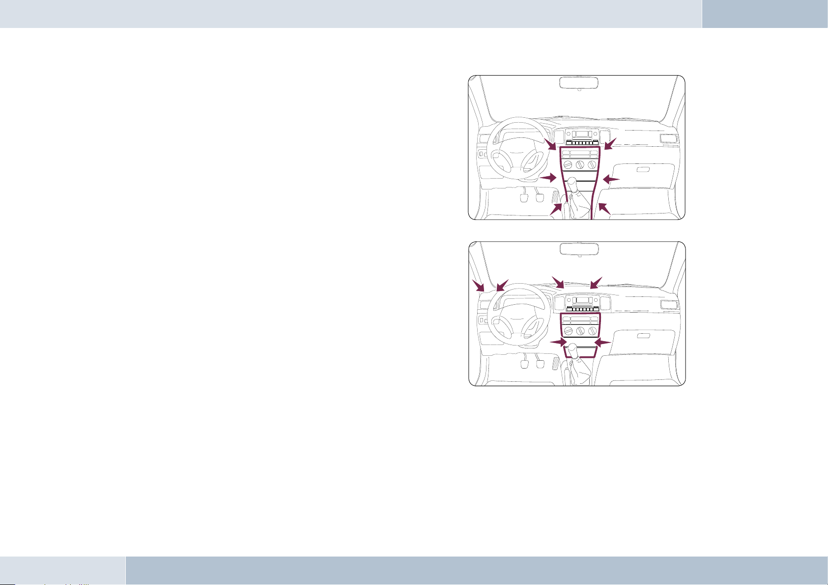
Suitable locations for the electronics box:
Passenger side, next to the middle console under the paneling,
model-specifi c installation console (dealer).
Our suggested installation locations are shown in the illustration on the right.
Further unsuitable locations are:
Leg and knee height, potential head impact zone, airbag infl ation space, engine compartment
6.2.3 Selection of site for installing the microphone
Suitable for the microphone:
Where voice can reach the microphone unhindered (distance
between the speaker and the microphone should be approx.
13.78 in), on the A-column (between windshield and driver’s side
window), next to the driver‘s sun visor, on the dashboard
Unsuitable for the microphone:
Close to the speakers (less than 31 in), under the dashboard, in
the air stream from open windows or air vents.
Fig. 03:
Installation
location of the
electronics box
Fig. 04:
Installation location
of the microphone
The illustration
shows one of the
potential microphone
mounting locations.
Alternatively, the
microphone may be
attached to the sun
visor with the clip
provided.
10 | 11
Page 12
6.2.4 Selection of site for installing the radio controller
The following locations are suitable for the radio controller:
In the area above the DIN installation slot, in the vicinity of
the steering wheel (at a location within the driver’s reach)
The following locations are unsuitable for the radio
controller:
Airbag deployment area, possible head impact area, beyond
the reach of the driver
6.2.5 Selection of site for installing the display
The following locations are suitable for the display:
In the space above the DIN installation shaft, close to the
steering wheel (in an easily accessible and visible position),
Note the position of sunlight to avoid refl ection on the display
The following locations are unsuitable for the display:
Airbag infl ation space, potential head impact zones, out of
reach of driver’s reach
Fig. 05:
Installation location
of the radio controller
Fig. 06:
Installation location
of the display
EGO LOOK
Page 13
6.3 Installation
q
DAMAGE TO ESSENTIAL VEHICLE COMPONENTS! – Essential vehicle components or wiring can be damaged when
drilling mounting holes or screwing in self-threading screws. Please make sure there is always suffi cient space behind
the screw holes and drilled holes!
6.3.1 Mounting the electronics box
Installation consoles for a number of
car models are available from your
dealer. These are designed to contain all
the system components, including the
electronics box. When it is not possible
to use an installation console, please
proceed as follows:
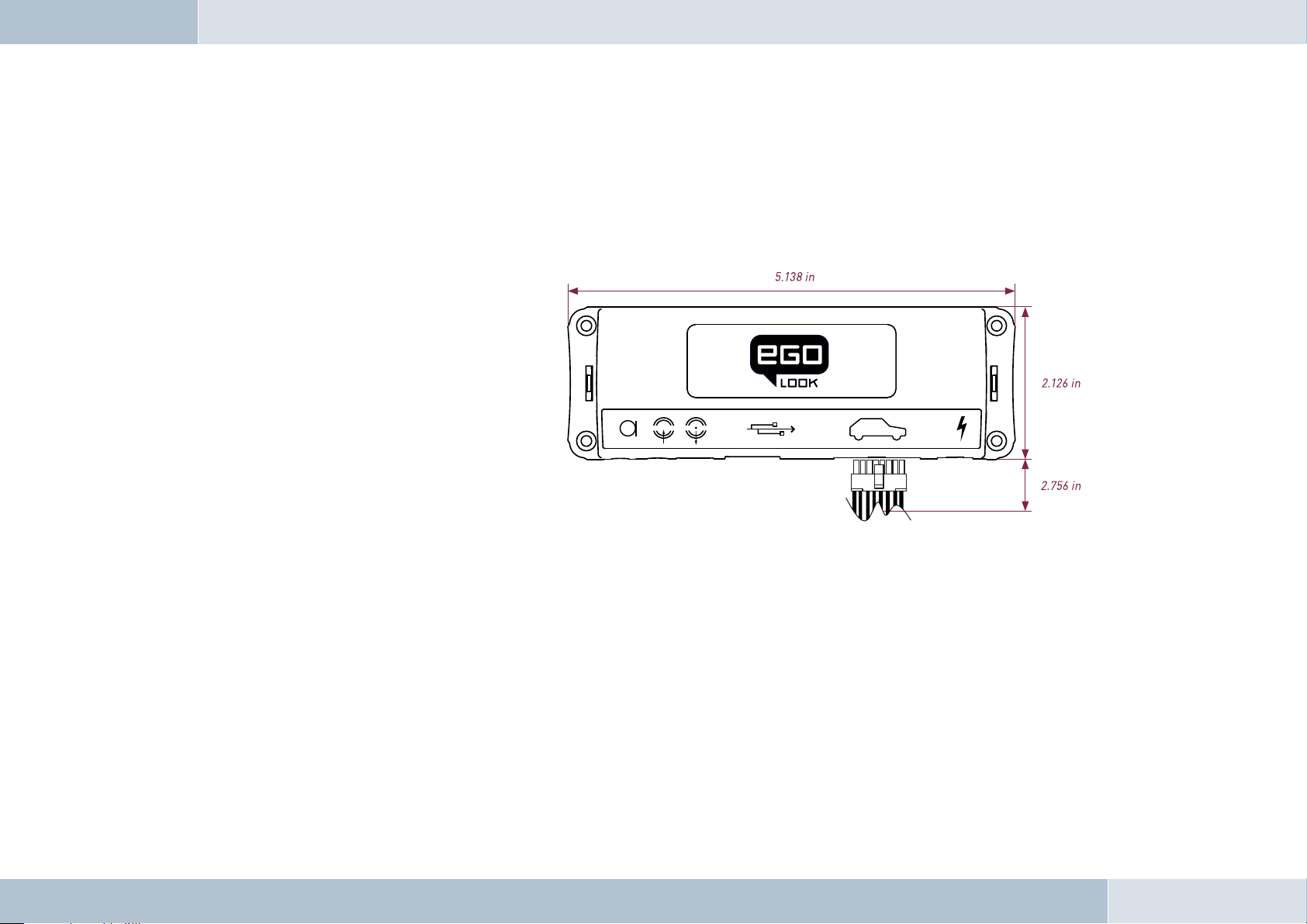
Defi ne the mounting points
Making sure that there is at least 2.8 in
space for the plug and socket connectors. Mark the positions for the fi xing screws.
Mounting the electronics box
For mounting the electronics box, use four self-threading screws and appropriate washers. We recommend size
“ST 2,9x25 DIN 7981”self-threading screws. These are ideal for the fi xing of the electronics box. Pre-drill the holes
with a 0.08 in drill.
Fig. 07:
Assembly dimensions
of the electronics box
6.3.2 Mounting the microphone
Defi ne the mounting location
The microphone holder has a self-adhesive strip on the back. The mounting location should have the same form and area
12 | 13
Page 14

as the self-adhesive strip on the microphone holder. The location selected must allow the microphone cable to reach the
electronics box! Position the microphone with the head facing towards the direction of speech.
Cleaning and degreasing the mounting location
The mounting location must be clean and free from grease and dirt/dust. Prior to installation, clean the area with a
cleansing product containing ethyl alcohol. Only use products that do not damage plastics or varnished wood fi nishes
and are themselves free of oils or grease. Unsuitable cleansers are, for example, lighter fl uid, acetone, turpentine,
trichloroethylene and similar products.
Attaching the microphone holder
Peel off the protective backing from the self-adhesive strip. Hold the microphone holder at a distance of several
millimetres (about a quarter of an inch) above the desired mounting location. Re-check the positioning. Re-positioning
after mounting is no longer possible. Place the microphone holder on the mounting location and fi x by applying short and
light pressure.
Attaching the microphone
Attach the microphone by sliding it into the holder and position the microphone head towards the direction of speech.
6.3.3 Inserting the battery in the radio controller
Rotate the lower portion of the controller clockwise and the upper portion counterclockwise to open the controller. Lift
the upper portion. Insert the supplied battery with the positive terminal downward into the lower portion until it latches.
Now place the upper portion on the bottom so that the contacts from the bottom of the controller touch the contact
surface in the upper portion. Position the latching tabs in the notches and rotate opposite the opening direction.
EGO LOOK
6.3.4 Mounting the radio controller
Defi ne the mounting location
The control console is mounted on a smooth service by means of the self-adhesive pad provided. Make sure that the user
can easily reach the controller.
Page 15

Cleaning and degreasing the mounting location
The mounting location must be clean and free from grease and dirt/dust. Prior to installation, clean the area with
a cleansing product containing ethyl alcohol. Only use cleansing products that do not damage plastics or varnished
wood fi nishes and are themselves free of oils or grease. Unsuitable cleansers are, for example, lighter fl uid, acetone,
turpentine, trichloroethylene and similar products
.
Gluing the radio controller in position
Remove the protective foil from the adhesive pad on the underside of the controller. Hold the radio controller a few
millimeters over the desired installation position. Check the position again – when doing so, keep the position of the red
and green buttons in mind. It is not possible to correct the controller after it has been glued in position. Place the radio
controller on the adhesive location and briefl y apply moderate pressure.
6.3.5 Mounting the display
Determining the mounting location
The display is mounted to a smooth surface using the supplied adhesive pad. The optimal position for this is facing
directly at the driver. Keep the effect of lights and sunlight in mind in order to minimize possible refl ections.
Cleaning and degreasing the mounting location
The mounting location must be clean and free from grease and dirt/dust. Prior to installation, clean the area with
a cleansing product containing ethyl alcohol. Only use cleansing products that do not damage plastics or varnished
wood fi nishes and are themselves free of oils or grease. Unsuitable cleansers are, for example, lighter fl uid, acetone,
turpentine, trichloroethylene and similar products.
Gluing the display in position
Pull the protective foil from the adhesive strips. Hold the display a few millimeters over the desired installation position.
Check the position again. It is not possible to correct the display after it has been glued in place. Place the display on the
adhesive location and briefl y apply moderate pressure.
Changing the base position
As supplied, the display base is intended for vertical mounting in the vehicle. To change to the horizontal mounting
position, unlatch the base, rotate 180° and re-latch the base on the underside of the display.
14 | 15
Page 16
6.4 Connection scheme
Installation for call reception for a car audio system with a mute input but without a phone input
With this connection option, voice playback is is emitted from the front right car speaker. During calls, the mute input
blocks the car audio signal.
q
NOTE: Please observe the information in section “6.5.1 Checking the mute inputs” on connecting the mute lead of the ISO
connecting cable.
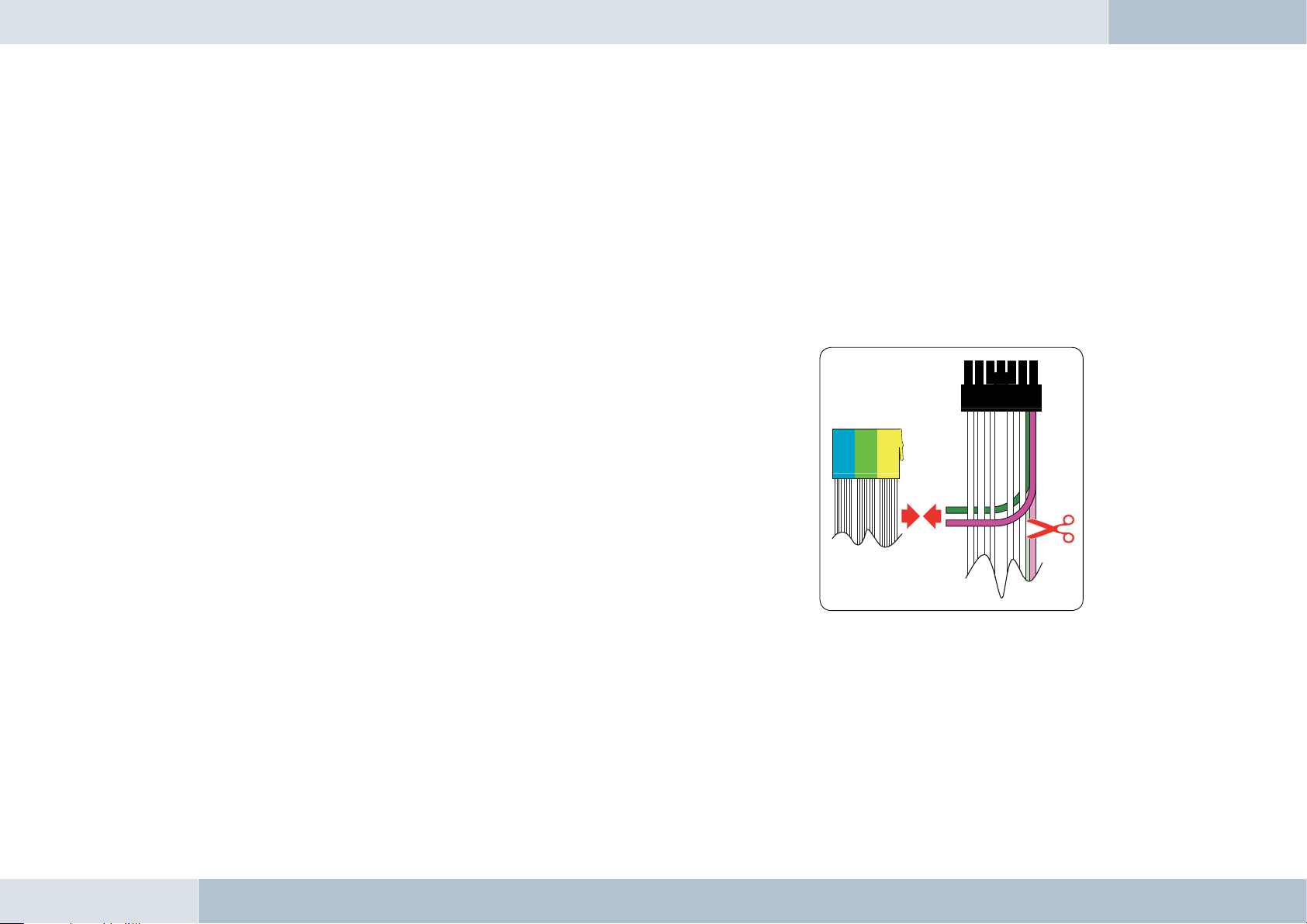
Installation for voice playback with a car audio system with phone and
mute input options
With this connection option, voice playback comes through the car audio
system speakers. During calls, the car radio output is switched to the phone
input by the mute input In order to access the phone input of your car audio
system, the speaker output of your EGO LOOK must be connected to the
phone input of your car audio system. The purple and green leads of the ISO
cable must be connected to the car audio phone input for this option. The
purple and green leads must be disconnected from the ISO connector. The
green lead (pin 14 of the 14-pin plug) should be connected to „Phone Out“,
and the purple lead (pin 7 of the 14-pin plug) to „Phone In +“ of the Mini-ISO
socket.
For information on the phone connection options of your car audio system,
please consult the manufacturer‘s user manual.
Fig. 08:
Connection for the
mini ISO connection
cable
EGO LOOK
q
NOTE: If your car audio system has different phone connection options from those mentioned here, please consult a
qualifi ed professional for installation of the system. Furthermore, please read the section with information on connecting
the mute lead of the ISO connection cable, “6.5.1 Checking the mute input”.
Page 17
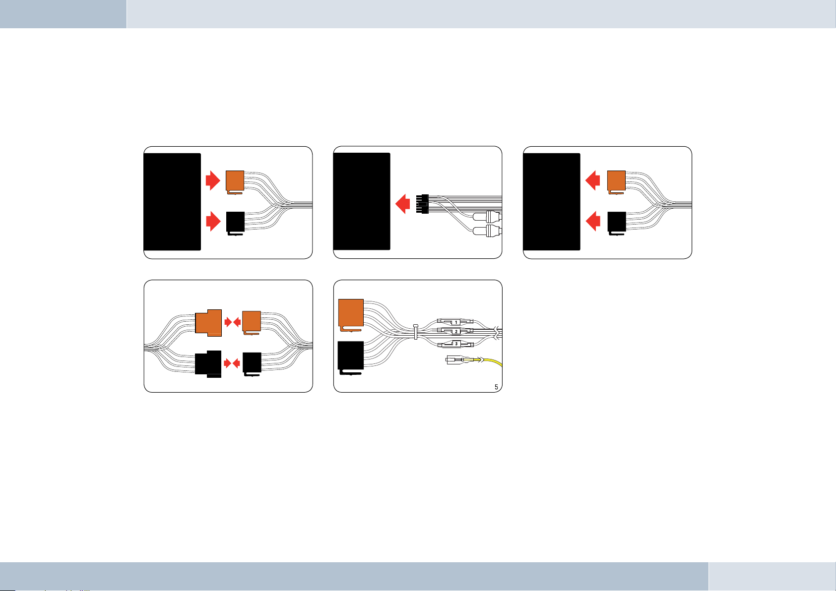
6.5 Installing the ISO connection cable
2
1
3
4
The battery must be disconnected before starting cable installation. Disconnect the grounding cable from the negative pole
of the battery. The cable installation procedure is shown in the illustrations.
Fig. 09:
Installation
procedure
Connect 14-pin ISO
connecting cable to
EGO LOOK
Car audio
Car audio
Disconnect ca r wiring
harn ess from ca r radio
Electronics box
Connect EGO LOO K ISO connec tors to car
wiri ng harnes s ISO connec tors
Connect yello w mute lead to
one of th e three mute in puts
(see table)
When the installation is completed, reconnect the grounding cable to the negative pole of the battery.
Connect EGO LOO K ISO
conne ctor to car r adio
6.5.1 Checking the mute inputs
The mute inputs 1-3 can be seen in Fig. 5 of Illustration 09. The yellow mute cable of the hands-free equipment is
connected to one of these inputs. The table below shows which mute input is to be used:
16 | 17
Page 18
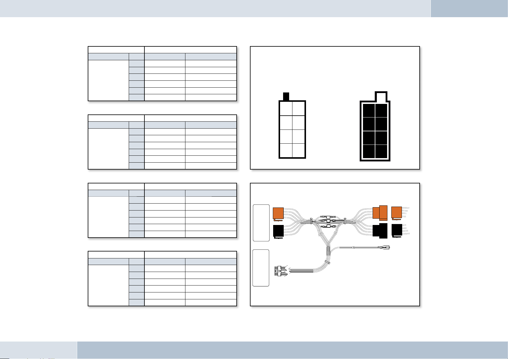
Fig. 10:
Setting the
PIN according
to device type
Socket contact housing
Radio model Pin Wire colour Function
1
Audi,
Volkswagen,
Grundig
2
3
4
7
8
blue Ignition (15)
red Permanent positive (30)
brown Ground (31)
Mute
Wiring of power supply connectors
Socket wiring from
the rear (see table)
Plug wiring from
the rear
Socket contact housing
Radio model Pin Wire colour Function
1
Ford,
Mercedes,
Porsche,
Becker
Radio model Pin Wire colour Function
Blaupunkt
Radio model Pin Wire colour Function
Philips
2
3
4
7
8
1
2
3
4
7
8
1
2
3
4
7
8
red Permanent positive (30)
blue Ignition (15)
brown Ground (31)
Socket contact housing
red Permanent positive (30)
blue Ignition (15)
brown Ground (31)
Socket contact housing
red Permanent positive (30)
blue Ignition (15)
brown Ground (31)
Mute
Mute
Mute
21
43
65
87
Car audio
Autoradio
Elektronikbox
Electronics box
12
34
56
78
Fig. 11:
Connector assignments
KFZ-Kabelbaum
Vehicle wiring harness
Fig. 12:
Connection system
EGO LOOK
Page 19
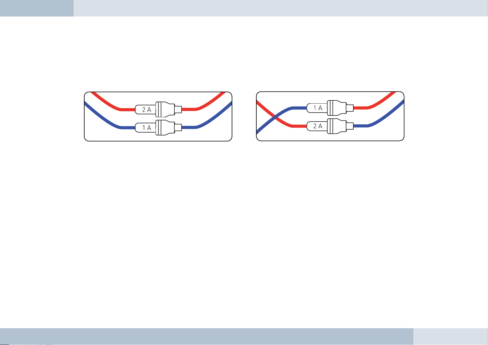
6.5.2 Checking the installation
When the ISO connection cable is correctly installed, a call remains active until the call is ended, even if the ignition has
already been turned off beforehand. The system switches off automatically when the call has been ended. If the system
switches to off immediately switches off,then exchange the ignition lead (blue) with the power supply lead (red) as shown in
Fig. 13b.
Fig. 13a:
View of original
connection
q
Fig. 13b:
View after
changing cables
PLEASE NOTE: the fuses should remain in place when opening the fuse compartment, make sure that they are not
inadvertently exchanged!
6.5.3 Additional external speakers
In the following cases, additional speakers (4 Ω, min. 5 W) must be used:
→ when the car audio system speakers should not be used
→ when the output rating of the speaker channel is greater than 35 W (Sinus) and the car audio
system has no phone connection option
→ when the car audio system is used with active speakers and has no phone connection option
Feedback interferes with the clarity of calls. Mount additional speakers at a distance of at least 31 in from the microphone.
When mounting additional speakers, please observe the manufacturer‘s installation instructions. Speakers can be
connected to the green (pin 14) and the purple (pin 7) leads of the connection cable. First of all, the purple and green leads
must be disconnected from the ISO connector (see Fig. 14).
18 | 19
Page 20
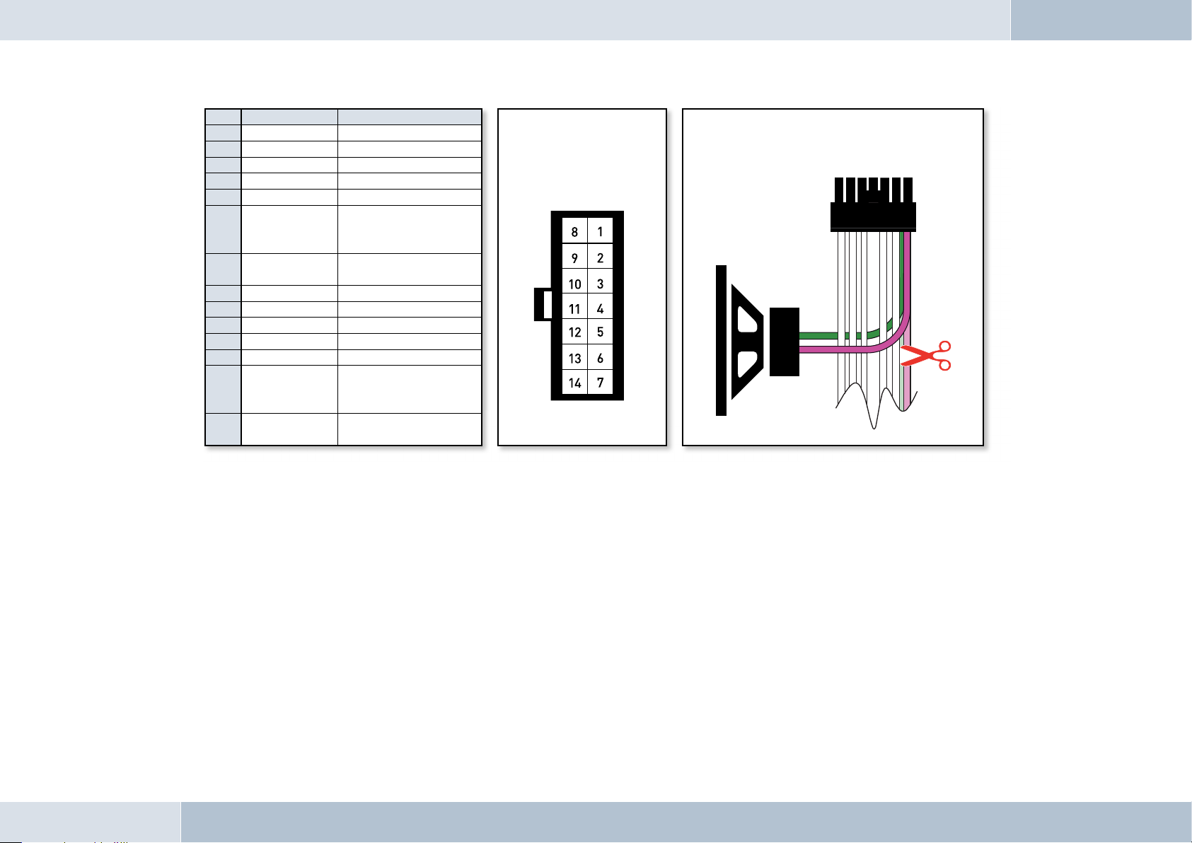
Pin Colour Function
1 Brown Ground (31)
2 Yellow Radio mute
3
4
5
6 White
7 Purple
8 Red Permanent positive (30)
9 Blue Ignition (15)
10
11
12
13 Black
14 Green
Car audio speaker
output +
(front right)
Speaker lead +
(front right)
Car audio speaker
output -
(front right)
Speaker lead -
(front right)
View of the plug side,
from which the wiring is
fed in the plug housing
(with pin allocation)
6.6 Connecting the components to the electronics box
Connection option for additional speakers on pin 7
(purple lead) and pin 14 (green lead) of the 14-pin plug
Fig. 14:
Connecting external
loudspeakers
EGO LOOK
q
The individual components are connected to the electronics box as follows:
[1] Plug the microphone jack into the jack socket with the microphone symbol
[2] The electronic box line-in can be used to connect an optional MP3 player with line-out. To do so, a connection
cable 0.14 in stereo jack plug to 0.14 in stereo jack plug (l = 4.92 ft) is required.
IMPORTANT: Only connect the device (MP3 player, iPod™, etc.) to the electronics box line-in with a jack cable when it
is being powered by battery alone (without the recharger), as interfering impulses may otherwise cause damage to the
electronic box line-in.
Page 21
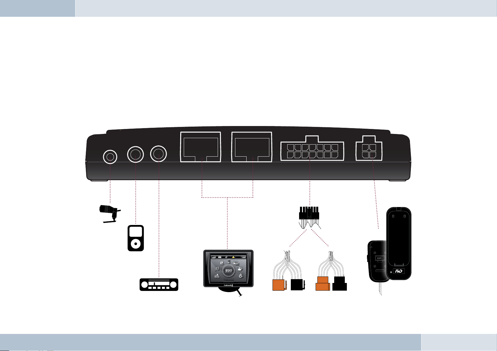
Fig. 15:
FFF
F
Connecting
electronics box
[3] The electronics box line-out must be connected to the car audio line-in. Depending on the car audio line-in
confi guration, one of the following cables is required:
→ Connection cable 0.14 in stereo jack to 0.14 in stereo jack (l = 4.92 ft)
→ Connection cable 0.14 in stereo jack to RCA plug (l = 4.92 ft)
→ Connection cable 0.14 in stereo jack to Mini-ISO (l = 4.92 ft)
[4] The display must be connected to one of the two jacks.
[5] The 14-pin plug of the ISO connecting cable must be connected with the electronics box.
[6] The base plate for the charging cradle may also be connected to the “charger” output socket.
[1]
FWD
[2]
[3]
52
T-Mobile
[4]
[5]
[6]
20 | 21
Page 22

Operating instructions
7
q
q
ROAD SAFETY RISK! Failure to pay attention can lead to dangerous situations in traffi c. You must always direct your
complete attention to current traffi c conditions, even when speaking with a hands-free device. It is advisable to avoid
phone calls while driving in diffi cult traffi c situations!
NOTE! Depending on the software version and the mobile telephones used, certain functions may not be available. For
more information, visit www.fwd-online.de.
7.1 Fe atures
7.1.1 Overview of features
The hands-free EGO LOOK system supports the Bluetooth® hands-free profile. The EGO LOOK is the convenient system
for phoning in your car. It provides the following capabilities:
→ Call functions, such as incoming/outgoing calls, call waiting, alternate between calls,
conference calling, and redial
→ Integrated voice control
→ Intuitive voice dialing directly from your mobile phone’s contacts list (without training)
→ Allows users to read and reply to SMS messages
→ Voicemail
→ Dictation function
→ Contacts list and call lists
→ Music player – replay of music files on mobile phones, iPodsTM or MP3 players via
Bluetooth® Audio Streaming (A2DP)
→ Automatic radio muting
→ Can be buddied with up to 10 mobile phones
EGO LOOK
Page 23

7. 2 C o n t r o l s
The EGO LOOK controller has three buttons.
The picture to the right gives a brief overview of
the device’s buttons. This section explains the
functions of the individual buttons.
Button functions
You use the rotary knob to navigate through the menus and to select the active menu. Another
function is the Voice control, which is activated by holding down the rotary knob. Numbers and
letters can be selected using the rotary knob in the “Speller”. You will find more information on
the “Speller” and “Voice control” in the corresponding chapters.
Brief description: Menu navigation, starting Voice control, entering numbers and letters,
selecting the active menu, stopping the screen saver
The green button is used for accepting an incoming call. Additional functions of the green button:
→ In the main screen: Selecting the active menu.
→ In the menus: Selecting the active menu.
→ In the contact list and the contact history: Starting a call to the currently selected number.
Brief description: Accepting, selecting a menu, starting a call to the currently selected number,
stopping the screen saver
22 | 23
Page 24

The red button is used to reject an incoming call. The red button can also be used to end a current
call. Additional functions of the red button:
→ In the menus: Returning from the current submenu.
→ In edit mode: Returning from the current submenu.
Brief description: Rejecting, hanging up, returning from the current submenu,
stopping the screen saver
q
NOTE: The EGO LOOK has a screensaver. After 60 seconds of inactivity, the brightness of the display is reduced.
The display becomes brighter again after any button is pressed. At the same time, the button pressed performs the
associated function.
7.3 Getting started with the EGO LOOK controller
Battery type
→ Only use CR2477 type lithium batteries. Other batteries can cause the unit not to operate properly or may
even damage it.
→ The manufacturer assumes no liability for damage caused by the use of incorrect batteries.
→ The battery is not rechargeable.
Inserting the battery
→ While looking at the and buttons, rotate the lower portion of the controller clockwise and the upper
portion counterclockwise to open the controller. Lift the upper portion.
→ Push the battery with the positive terminal (+) facing downward at an angle into the battery compartment and
latch it in place. When inserted, you should not be able to see the labeled side of the battery.
→ Place the upper portion on the bottom so that the contacts of the bottom of the controller touch the contact
surface in the upper portion. Place the latching tabs in the notches and rotate opposite the opening direction.
EGO LOOK
Removing the battery
→ While looking at the and buttons, rotate the lower portion of the controller counterclockwise and the
Page 25

upper portion clockwise to open the controller. Lift the upper portion.
→ Remove the battery from the battery compartment and then put the controller back together again.
Activating the controller with the EGO LOOK
→ The controller must initially be activated with the EGO LOOK.
→ Switch on the EGO LOOK.
→ Within the first 10 seconds after switching the EGO LOOK on (indicated by the display backlighting being turned
on), press the and buttons simultaneously for at least one second until the LED between the buttons
is illuminated.
→ The controller has now been activated with the EGO LOOK and can be used. After changing the battery, it is
unnecessary to perform the activation again.
Disposing of used batteries
→ Do not discard used batteries in household garbage.
→ Return used batteries to a designated collection point (e.g. your dealer or an electronics store).
7. 4 S y m b o l s
7.4.1 Symbols in the status bar
Fig. 16: Status bar
The status bar is a located at the top of the display and shows the
symbols described in this section.
24 | 25
Page 26

Field strength symbol – indicates the
current strength of the reception fi eld
SMS symbol – indicates text messages
received
Arrow symbol – indicates missed calls
FWD
Indicates the user’s initials
Battery symbol – indicates the battery
capacity of the mobile phone
7.4.2 Speller symbols
Symbol for confi rming input
Symbol to delete the last character
Symbol for changing to numeric input
EGO LOOK
az
Symbol for changing to lowercase letters
Symbol for changing to uppercase letters
Symbol for changing to special characters
Symbol for exiting the speller
Page 27

7.4.3 Symbols for menu options
Activated option. This symbol appears in front of an activated menu item.
Deactivated option. This symbol appears in front of a menu item when it may
be activated as an option.
7.4.4 Contact list number types
Symbol for personal telephone numbers
Symbol for mobile telephone numbers
Symbol for business telephone numbers
7.4.5 Music player symbols/buttons
Symbol for selecting the device
Symbol for setting the volume
Play, pause
Stop
Track skip, forward
Track skip, reverse
26 | 27
Page 28

7. 5 S p e l le r
The controller controls the EGO LOOK using the rotary knob. In addition, the rotary knob is used for confi rmation. The
button is used to go one step back or to exit the menu. The Speller allows you to compose telephone numbers
from individual digits or names from individual letters. It is available for various functions of the EGO LOOK, for example,
for dialing a telephone number or for creating a contact list entry. Operating the Speller is explained in the following:
→ Entering numbers
By rotating the rotary knob, navigate to a digit and accept this digit by pressing the rotary knob. You can delete
the last digit of the number by selecting the symbol. Once the number has been completely entered, you
can confi rm it by selecting the symbol. To cancel the process at any time, press the button.
→ Entering names or text
Similar to the method used for entering numbers, you can enter names or even entire texts using the Speller.
Navigate to a character by rotating the rotary knob and accept it by pressing the rotary knob. You can delete the
last character by selecting the symbol. Once the name has been completely entered, you can save it by
selecting the symbol. To cancel the process at any time, press the button. You can switch between
upper-case letters, lower-case letters, numbers and special characters using the symbols described in Chapter
7.2.3. You select these symbols using the rotary knob.
EGO LOOK
7.6 Getting st arted
Take enough time to familiarize yourself with the use of the EGO LOOK in combination with your mobile phone. First of
all, make a few calls to determine the ideal volume and the best voice pickup direction before using the EGO LOOK in
traffi c.
When getting started, your car should be parked in a quiet place. It is also helpful if the person you will be calling can
take time to let you make some test calls.
Page 29

7.6.1 About Bluetooth® technology
®
Bluetooth
technology is a wireless technology and, as such, it allows communication between individual devices without
the need for cables. Data and voice information can be transmitted simultaneously. It is unnecessary to have line-ofsight routing between the devices. The transmission/reception range in the open is typically 33 feet. Interference from
other electrical or electronic equipment or obstacles may, however, reduce this range. The frequency band, in which
Bluetooth® operates, is reserved virtually worldwide. This, coupled with the fact that each Bluetooth® product is tested
and approved for compatibility with other Bluetooth® devices, ensures the highest possible levels of compatibility with
devices from a wide range of manufacturers. The EGO LOOK system supports the Bluetooth® hands-free profile. This
means that it is fully compatible with all phones supporting the Bluetooth® hands-free profi le. If you are uncertain, read
the operating instructions for your mobile phone to see which profi les are supported.
A2DP (Advanced Audio Distribution Profi le) is a technology that enables the wireless transmission of stereo audio
signals via Bluetooth® to a compatible receiving device. Please take a look at our homepage for information about
compatible mobile phones
7.6.2 Activating the controller
You can read how to activate the radio controller with the EGO LOOK in Chapter 7.3 „Getting started with the EGO LOOK
controller“ in „Activating the controller with the EGO LOOK.“
7.6.3 On / Off function
The fi rst time you use your EGO LOOK, you need to start it by switching on the ignition. You will see the start logo
followed by the main screen. If the EGO LOOK is not connected to a mobile telephone, or if no user is found, the
functionality of the main menu is limited.
To establish a connection to the EGO LOOK, you need to select the menu item „Manage users“ using the rotary knob.
There, you select „New user.“ The EGO LOOK then searches for mobile telephones in its reception range. If your mobile
telephone is not found, you can start a search again or read the „Troubleshooting“ section. If the name of your mobile
telephone is displayed, select it by pressing the rotary knob. Once connected with the EGO LOOK, complete functionality
28 | 29
Page 30

is available in the main menu. Capabilities not supported by the mobile telephone cannot be selected. Once the ignition
is switched off, the EGO LOOK powers down. If the ignition is switched off during a telephone call, this telephone call is
maintained. The EGO LOOK does not power down until the telephone call has been completed.
®
7.6.4 Entering the Bluetooth
PIN
After a few seconds you will be prompted to enter your Bluetooth® PIN. Enter the PIN shown on the EGO LOOK display
onto your mobile phone.
7.6.5 Hands-free mode
In some cases, coupling with your mobile phone in the hands-free mode does not work when using the method described
above. If you are sure that your mobile phone supports the Bluetooth® hands-free profi le, proceed as follows: In the
®
list of detected devices, select “couple from phone”. Now you need to search for Bluetooth
devices using your mobile
phone. The procedure for this can be found in the operating instructions for your mobile phone. The mobile phone will
then start searching for devices. Select the EGO LOOK from the list of devices found by your mobile phone. During the
coupling process, your mobile phone will prompt you to enter a PIN or password. At this point, please enter the series
of numbers shown on the display of the EGO LOOK. After a short time, the mobile phone should inform you that coupling
was successful. You may also cancel the coupling at any time by pressing the key. If coupling fails, please read the
section on “Troubleshooting”.
EGO LOOK
7.6.6 Automatic coupling
If the phone is already connected with the EGO LOOK, the EGO LOOK will try to couple to this phone. If the search is
successful, a connection is automatically established. A search is always performed for the most recently connected
mobile phone.
If the search process was unsuccessful, it‘s possible that Bluetooth
®
or the mobile phone is not turned on, or that you
were not the last user. If you would like to select another user, activate user management and log this user in.
Page 31

7.7 The menus
Using the rotary knob, navigate to a menu item. Select a menu item using the rotary knob or exit the menu by pressing
the button. By pressing the rotary knob again, you select the submenu of the current menu. You can select from
the following menu items listed in the menu overview below:
→ User management
User-specifi ed settings such as “change initials”, “log in”, “log out”, etc., can be set out under this menu item. New users
can also be logged on. For details, please see the “User management” chapter.
→ Settings
General settings for the EGO LOOK can be entered under this menu item. These range from “Ringtone” to “Software
update” to “Voicemail”. The exact breakdown can be found in the following overview, which depicts the menu structure.
You can fi nd more information in the “Settings” chapter.
→ Music player
The “Music player” menu allows you to playback songs and to control them as usual with Play, Pause, Stop, Forward,
and Reverse. The playback device can be coupled to the EGO LOOK under “Options”. For details, see the “Music player”
chapter.
→ Dictation function
The dictation function allows you to record and playback memos. All voice recordings are listed under the menu item. The
dictation function is described in detail under the chapter of that name.
→ Contacts list
The contacts list contains the entries downloaded from the mobile phone. Each number in an entry can be accessed. In
addition, direct outward dialing is possible here (without voice control). You can fi nd more information in the “Contacts
list” chapter.
30 | 31
Page 32

→ Call history
This contains lists of the last dialed numbers, accepted calls, and missed calls. You can mark an entry using the rotary
knob and start a call using the button. You will fi nd more information in the „Call history“ chapter.
→ Messages
Contains the list of text messages (SMS). Unread messages are marked accordingly. The messages menu is divided into
“Read messages” and “New message”. More information can be found in the “Messages” chapter.
EGO LOOK
Page 33

Main menu structure for the EGO LOOK
User management Settings Music player Dictation function Contacts list Call history Messages
→
New user
→
User 1 - Melody - Play
→
Ringtone
→
Playback
→
New recording
→
Recording 1
- Change initials - Volume - Pause - Listen
→
- Change icon color
- Log in
Brightness - Stop - Delete
→
Call settings - Forwards
→
Recording 2
- Log out - Send number - Reverse - Listen
→
- Delete - Call waiting
→
User 2 - Automatic answer - New device
- Change initials
- Change icon color
- Log in
- Log out
- Delete
→
...
→
User 10
→
Direction of rotation - Device 1 - Listen - SIM
→
Delay - Connect - Delete - Telephone
→
Factory settings - Disconnect
→
Software update - Delete
→
Info - Device 2
→
Help - Connect
→
Language - Disconnect
→
Voice control - Delete
Options - Delete - Direct dial - Send
→
Recording 3 - Synchronize - Edit
→
... - SIM + telephone
→
Recording ...
- Start - Device ...
- Recognition language
→
Audio management
- Mic sensitivity
- Line in
- Volume
- Line out
→
Voicemail
- On / off
- Record text
- Listen to text
- Listen to recording
→
Switch off
→
Search
→
Entry 1
→
Entry 2
→
...
→
Entry ...
→
Options
→
Missed call
→
Calls received - Call back
→
Number dialed 1 - Answer
→
Number dialed 2 - Send
→
... - Edit
→
Number dialed ...
→
Read message
→
New message
32 | 33
Page 34

7.7.1 Us er management
Symbol:
The EGO LOOK allows you to manage up to 10 user profi les; you can quickly and easily switch between these profi les
while using the EGO LOOK. Individual information saved for each user includes the following:
→ Contacts list
→ Display brightness
→ Ringtone
→ Display language
→ Volume settings
→ Voicemail
→ Dictation device
→ Call lists
Starting the Manage users function
To reach the Manage users function, go to the symbol on the main screen and press the rotary knob. Then, you
will see the users linked to the EGO LOOK and the „New user“ item. If no users are linked, only the „New user“ item is
present.
EGO LOOK
Create a new user
To activate a new user, you must select the „New user“ item using the rotary knob and then press the rotary knob. All
further steps are similar to those in the „Getting started“ chapter.
Change user initials
Open Manage users. Then, select a user and press the rotary knob. This brings you into a submenu. From there, select
the „Change initials“ item. Using the Speller, you can now edit the name of the user.
Page 35

Change icon color
In this item, the user can change the color of the user symbol . Ten colors are available.
Reset user
To delete all user data, open Manage users. Select the user to be reset. Confi rm your selection by pressing the rotary
knob. A menu opens. In this menu, select the „Delete“ item. All user data is now deleted from the EGO LOOK.
Change users
To change users, move into Manage users and select the desired user. Confi rm your selection by pressing the rotary
knob. A submenu opens. Select the „Activate“ item. The previous user is deactivated and the new user activated. If
the selected user can be found, the change in users takes place immediately. If the user cannot be found, the program
returns to Manage users.
Log out user
®
You can disconnect the current Bluetooth
connection within “User management” under the current user with the “Log
out” menu item.
7.7. 2 Call ing
If there is a Bluetooth® link between the EGO LOOK and a mobile telephone, you can use the hands-free capability of your
EGO LOOK. You can dial a number using voice dialing, the menu, or directly on the mobile telephone.
Incoming call
If the mobile phone is available over the Bluetooth
®
connection, the call is signaled with the ringtone on your mobile
phone. Otherwise a signaling tone is generated by the EGO LOOK.
If the caller has not blocked his number and if the mobile telephone supports this function, the number, or the name
of the caller if a corresponding entry is found in the contact list, is displayed. You can decide to accept the call (
button) or reject it ( button). If you accept the call, you can regulate the volume using the rotary knob. The setting
is stored. You may end the call by pressing the button.
34 | 35
Page 36

Call setup
®
Call setup from the EGO LOOK is only possible if there is an existing Bluetooth
the mobile phone. You may set up a call with voice-activated dialing or through the menu.
To activate voice dialing, press the rotary knob for longer than a half a second. With the command „Dial number,“ you can
announce the telephone number to be dialed or with the „Dial <Name>“ command you can dial an entry in the contact list
directly. You can fi nd more information on this in the „Voice control“ chapter. (Take paragraph into account)
The following methods may be used to initiate a call from the menu:
→ by selecting from the contacts list and the mobile phone
→ by direct outward dialing of a number with the number speller
→ dialing from the call list on your mobile phone
→ through the call-back feature for received SMS messages
And lastly, you may also dial a number directly on your mobile phone.
connection between the EGO LOOK and
EGO LOOK
q
q
IMPORTANT NOTE: Please observe your country’s regulations on in-car telephone use!
Call ended
Once a call is ended, the menu jumps back to the main menu. If an incoming call is rejected with the key, the menu
jumps to the previous menu.
Setting the volume
You can regulate the volume during a call and during active speech recognition using the rotary knob.
TIP! If the person you‘re speaking with cannot hear you well, consider increasing the sensitivity of the microphone in the
“Audio management” menu under “Settings”. There is a risk, however, that this may produce annoying echoes.
Page 37

Options during phone calls
During a phone call, the following options can be carried out once the rotary knob has been turned:
→ DTMF tones
→ Mute mic.
→ Private mode
→ Record
→ Alternate between calls
→ DTMF tones
Here, touch key tones are selected and then sent by means of the speller.
→ Mute mic.
With this option, the microphone can be switched to mute. The person you have been speaking with can then no longer
hear you. Pressing again deactivates the muting of the microphone.
→ Private mode
You can also switch into Private mode during a telephone call by selecting the „Private mode“ item and confi rming with
the rotary knob. The call now only uses the mobile telephone. Communication by way of the EGO LOOK is not possible
at this moment and anyone else in the vehicle cannot listen to the conversation. Pressing the rotary knob again ends
Private mode.
q
Important note: In most countries, phoning while driving is only allowed when using a hands-free system.
→ Record
If the need to record an important call arises, this can be achieved with the “Record” function. The person you are
LOOKing to is then informed that the conversation is being recorded. The recording can then be retrieved from the
“Voicemail” folder.
36 | 37
Page 38

→ Call waiting
If the call waiting feature in your mobile phone and the EGO LOOK is switched on, while you are LOOKing to another
person, incoming calls from third parties are signaled. The name or number of the third calling party is displayed, if
possible. You can accept the call with the key or reject it with the key.
If you accept the call of the third party, the active caller is automatically put on hold. If you reject the third calling party,
the conversation with the active caller is continued.
→ Call switching
You can switch between two callers by pressing the button. Then, you select the context menu item „Call
switching.“ The active caller is shown in the display as the top entry. You can switch back and forth between the callers
by pressing the button again. In the Call switching mode, the volume of the active caller can be changed using the
rotary knob.
→ Voicemail
If you are unable to answer a call, voicemail is activated, and information left by the caller is accepted. When the call is
ended or when the allotted recording time is exceeded, voicemail is switched off.
When voicemail is activated, the call is accepted in the background, and the user can listen along to the message; the
message is recorded.
If voicemail is activated by a caller in the call-waiting system, the call can not be heard by the user.
EGO LOOK
q
Important note: In most countries, phoning while driving is only allowed when using a hands-free system.
7.5.3 Contacts list
Symbol:
The mobile phone’s contacts list can be read via the “Contacts list” menu item. In addition to dialing numbers from the
contact information with the key, entries can be found more quickly with the search function. You may also
Page 39
download the contacts list from the mobile phone under the “Option” menu item, or enter the number via direct outward
dialing.
Read
To read numbers from the contacts list, please select the menu item. After opening the contacts list, all entries
contained in the list are displayed. Select the number or name you want to call and press the key. The numbers
stored under this name are then displayed. By pressing the key once again, the number is dialed.
Search
If searching for a particular name becomes diffi cult due to a large number of entries, the search function may be used.
With this function, entries may be searched for a specifi c name or specifi c fi rst letters. The desired name or fi rst letters
can be entered by using the speller. By pressing the key, the contacts list will be searched for this name or letter.
Direct dial
Direct dialing is possible in addition to voice-activated dialing. As described under the “Speller” and “Call setup” items, a
number can be entered here by hand using the speller. The call is set up after confi rming the number with the key.
Synchronizing
In the „Synchronize“ item, you can download the contact lists of the mobile telephone or from the SIM card into the
EGO LOOK memory. Both contact lists can be synchronized, too. Once you have selected a contact list, you confi rm this
with the rotary knob. Now a loading bar appears in the display. This bar indicates the instantaneous progress of the
synchronization process. If the download has been completed successfully, the entries are now found in the EGO LOOK
contact list. In addition, you can cancel the download manually using the button. If you decide to cancel, you must
reconfi rm this by answering the Yes/No question. If you answer „Yes“, the synchronized entries are deleted and the
program returns to the „Contact list“ menu. If you answer „No“, synchronization continues.
7.7.4 Call history
Symbol:
In the “Call history” menu item, you may view “Numbers dialed”, “Missed calls”, and “Calls received”. After selecting the
38 | 39
Page 40

“Call list” menu item, a list of numbers dialed is downloaded from the mobile phone. “Missed calls” and “Calls received”
may also be viewed by selecting the corresponding upper list entries. Some mobile phones do not support access to the
call list; in this case, a call list is maintained within the EGO LOOK.
7.7.5 Voicemail
The “Voicemail” item can be found under the “Settings” menu. It may be activated or deactivated here. It is also possible
to record a message that will be played when voicemail is launched. The recorded message can be played back in order
to check it. Information left by a caller within voicemail can be replayed under the “Listen to messages” item.
7.7.6 SMS
Symbol:
The EGO LOOK supports the sending and receiving of text messages. The menu is structured in same form users are
familiar with from their mobile phones. Messages received can be viewed under the “Incoming SMS” item. The sender
of the message can be called back by phone using the “Call-back” function. You may also reply to the sender with a text
message (SMS). In addition, new messages may be recorded. Various templates are available for this purpose. Here you
have the possibility to modify the templates as you wish, under the “Edit” item. To send, press the “Send” key and select
a name from the contacts list or enter the telephone number directly.
If for some reason the text message is not sent, the EGO LOOK informs the user and jumps back to “Edit text” mode.
®
If the mobile phone does not support the sending of SMS messages via Bluetooth
, then the “SMS” menu item cannot be
selected in the EGO LOOK.
EGO LOOK
7.7.7 Music player
Symbol:
The music player is activated through the main menu. The music player may also be activated without a mobile phone
Page 41

being couple to the EGO LOOK. In order to play back music, the EGO LOOK must be coupled to an A2DP-capable device
(such as a mobile phone with A2DP, an iPod™ or an MP3-Player with A2DP adapter).
Connection / coupling
Under the “Option” menu item, a “New device” may be coupled, or an already coupled device may be connected. A total
®
of 10 devices may be coupled, whereas only one device may be active. If a “New device” is selected, a Bluetooth
device
search is performed. The desired device can be selected from there.
If the music device does not support coupling from other devices, it is also possible to couple the EGO LOOK from the
music device via the “Couple from device” menu item. In both cases, a four-digit PIN code is displayed by the EGO LOOK,
which must be entered into the music device. Is the PIN is incorrect, the menu jumps back to device selection, and you
must repeat the process.
If an iPod™ or MP3 player with an A2DP adapter is used, these devices couple automatically with the EGO LOOK. For
this, the “Couple from device” menu item must be selected during the search for devices. After coupling, all playback
functions are available to the user.
Playback
The following functions are available for playback and are shown in the display:
→ Play
→ Pause
→ Stop
→ Forwards (by title)
→ Reverse (by title)
→ Volume setting (playback volume adjustable in 10 steps)
Return to the symbols using the rotary knob. For a description of these keys, please see the “Symbols” chapter.
40 | 41
Page 42

7.7.8 Dictation function
Symbol:
Recording
The Dictation function allows you to make your own voice recordings. This function is particularly useful when you do
not have pencil and paper at hand while driving the car. You now have the potential of storing important information as
a voice recording. To do this, select the „New recording“ item and confi rm using the rotary knob. If you manually stop
recording, this recording is stored in the list to be played back later. If the recording memory is full, a signal is given.
New recording is not possible again until old recordings have been deleted.
Playback
To play the recordings, select the appropriate recording and press the rotary knob twice. The recording is played for you.
Deleting
If you want to delete a recording, select the recording to be deleted and confi rm using the rotary knob and go to the
„Delete“ item. The recording is deleted by pressing the rotary knob.
7.7.9 Settings
EGO LOOK
Symbol:
The “Settings” menu is highly complex, since many settings for the EGO LOOK can be carried out under this menu item.
The following settings can be carried out:
→ Ring tone
→ Brightness
→ Call settings
→ Direction of rotation
Page 43

→ Follow-up time
→ Factory settings
→ Software update
→ Information
→ Help
→ Language
→ Voice control
→ Audio management
→ Voicemail
→ Power down
Ring tone
The „Ring tone“ menu is divided into „Melody“ and „Volume.“ Several ring tones are available under „Melody.“ You may
set these according to your personal tastes. You can set the „Volume“ of these ring tones using the rotary knob.
Brightness
The brightness of the display can be adjusted here to the needs of the user.
Call settings
→ Send number
The “Send number” feature can be switched on or off here. This setting is dependent on the network.
→ Call waiting
The call waiting feature can be switched on or off here. If this feature is activated, calls from a third party will be
signaled during an active phone call.
→ Automatic call answer
If this option is activated, incoming calls are automatically answered after three rings.
Direction of rotation
→ Clockwise
If this option is activated, rotating the knob clockwise signifi es advancing in the menu or the contact list.
42 | 43
Page 44

→ Counterclockwise
If this option is activated, rotating the knob counterclockwise signifi es advancing in the menu or the contact list.
Delay time
You may determine how long the EGO LOOK should remain active after switching off the ignition. The delay time may be
set in steps between 0 and 30 minutes.
Factory settings
This resets all settings back to the standard factory settings. In doing so, all user settings including the contacts list are
lost.
Software update
®
The software for your EGO LOOK can be updated via Bluetooth
. For more details, please see the section “Software
update”.
Info
Provides information about the various software and hardware versions of your EGO LOOK. Use this information when
you contact our service department with questions and problems.
Language
The EGO LOOK supports multiple display languages. You can change the display language within this menu item.
EGO LOOK
Voice control
→ Start
Carrying out this item launches voice control. Control is performed with specifi c commands. For more
information see the “Voice control” chapter.
→ Recognition language
If your EGO LOOK features multiple languages, you may select the language here.
Page 45

Audio management
→ Microphone sensitivity
Under certain circumstances, it may be necessary to adjust the microphone sensitivity. For example, if the
microphone is located too far from or too close to the driver. The EGO LOOK has 10 possible sensitivity settings
available. The sensitivities are shown to the right of the display as bars. There are a total of fi ve bars where one bar
indicates two steps. The sensitivity can be adjusted using the rotary knob. Do not set the microphone to be too
sensitive because this may result in over-modulation and poor audio quality for the other party.
→ Line in
In this menu item, you may activate the line in and vary the input volume of the audio device connected to the line
in of the electronics box.
q
Note: Please note that only the connection of an audio device with line level is allowed. If the electronics box’s line in is
overamplifi ed through an excessively high signal from the line out of the audio device, the volume must be reduced on
the audio device.
→ Volume
The base volume of the line out as well as the ringtone and call playback through the speaker output of the
electronics box can be adjusted within this menu item in 5 steps.
→ Line out
The channel for call playback can be set under this menu item. The items “right”, “left”, and “right + left”
are available.
Voicemail
Voicemail functions can be switched on and off here. The user still has the option to record and listen to messages and
to playback recordings. For more information see the “Voicemail” chapter.
44 | 45
Page 46

Power down
The current Bluetooth® connection is severed under this item and the EGO LOOK is switched off. The EGO LOOK may be
switched back on by pressing a single key.
7.8 Voice control
The dialogue-guided voice control of the EGO LOOK allows you to select a name or number via voice input. While
numerical selection allows you to directly announce a number, you also have the option to select the name directly from
the contacts list.
Switching the recognized language
Depending on the country version of your EGO LOOK, the voice recognition system supports up to three languages.
One of these may be activated. To change the active recognized language, select the item „Setting → Voice control
→ Recognized language“ in the menu. A list of available languages is now displayed. Select the desired language and
confirm by pressing the rotary knob. The EGO LOOK will now save your settings and begin updating the recognized
language. The status of this process is displayed for you using a progress bar.
Activation and sequence
Voice control is only possible if you are not making a telephone call. By pressing the rotary knob for longer than a half
a second while not engaged in a telephone call, the status text „Main menu“ is heard, and the message „Please speak“
appears in the display.
You may cancel each voice dialogue at almost any time with another prolonged pressing of the key. If the EGO
LOOK is waiting for a voice command, you may end the dialogue by saying “abort”.
If there is no Bluetooth
®
phone connected to the EGO LOOK, voice-activated dialing cannot be activated.
EGO LOOK
Page 47

The following voice commands are possible:
→ “Call / dial <name>”
→ “Call / dial <name> at home …
at work / in the offi ce / on business …
on the cell phone“
→ “Dial number”
→ “Show dialed numbers”
→ “Show missed calls”
→ “Show received calls”
→ “Store note / recording”
→ “Read notes / recording”
→ “Help”
→ “Redial / call again”
→ “Abort”
“Call / Dial <name>”
This command may be used to select a name from the contacts list. The name must be contained in the contacts list
for this command to function. If the name is not recognized or found, the EGO LOOK responds with “Please repeat”
and offers you the chance to repeat the command. If the name is recognized, you will be asked if the name should really
be dialed. The following commands are available to you:
→ “Yes / Call / Dial” Dials the number stored under that name
→ “No / Back” The number for the recognized name is not dialed
→ “Abort / Cancel“ Ends the dialogue without carrying out a function
→ “Help” Calls up Help and an explanation of possible commands
46 | 47
Page 48

“Call / Dial <name> at home … on the cell phone”
With this command, you may dial a specifi c type of number from a contacts list entry. If the name is recognized, you will
be asked if the name should really be dialed. The following commands are available to you:
→ “Yes / Call / Dial” Dials the number stored under that name
→ “No / Back” The number for the recognized name is not dialed
→ “Abort / Cancel“ Ends the dialogue without carrying out a function
→ “Help” Calls up Help and an explanation of possible commands
“Dial number”
You will be prompted to enter the number to be dialed. This may be done with individual numerals as well as groups of
numbers. If you insert a pause, the last number/group of numbers entered is repeated for checking. In addition, you will
be notifi ed if you exceed the maximum telephone number length. In addition to continuing with the entry of numerals, the
following additional commands are available:
→ „+, *, #, 0, 1, …, 9“ For entering the number
→ “Delete all” To delete the entire phone number entered
→ “Delete / Correct /
Change” To delete the last number/group of numbers entered
→ “Repeat” To announce the entire phone number entered up to this point
→ “Yes / Call / Dial” To dial the phone number entered
→ “No / Back” To not dial the number entered
→ “Abort / Cancel“ Ends the dialogue without carrying out a function
→ “Help” Calls up Help and an explanation of possible commands
EGO LOOK
Page 49

“Show dialed numbers”
This requires that numbers / names are included in the call list. If there is no entry, the EGO LOOK informs the user.
The announcement can be stopped at any time by pressing the button. Afterwards, the following commands are
available to you:
→ “Call / dial <name>” To dial the name in the call list
→ “Call / dial entry
number <1-20>” To dial a numbered entry in the call list
→ “Yes / Call / Dial” To confi rm the selection of the number/name
→ “No / Back” To not dial the number/name in the call list
→ “Abort / Cancel“ Ends the dialogue without carrying out a function
→ “Help” Calls up Help and an explanation of possible commands
®
Some mobile phones may not support a call list via Bluetooth
. If this is the case, the EGO LOOK cannot show any entries
with this command.
“Show missed calls”
This requires that numbers / names are included in the call list. If there is no entry, the EGO LOOK informs the user.
The announcement can be stopped at any time by pressing the button. Afterwards, the following commands are
available to you:
→ “Call / dial <name>” To dial the name in the call list
→ “Call / dial entry
number <1-20>” To dial a numbered entry in the call list
→ “Yes / Call / Dial” To confi rm the selection of the number/name
→ “No / Back” To not dial the number/name in the call list
48 | 49
Page 50

→ “Abort / Cancel“ Ends the dialogue without carrying out a function
→ “Help” Calls up Help and an explanation of possible commands
®
Some mobile phones may not support a call list via Bluetooth
. If this is the case, the EGO LOOK cannot show any entries
with this command.
“Show received calls”
This requires that numbers / names are included in the call list. If there is no entry, the EGO LOOK informs the user.
The announcement can be stopped at any time by pressing the button. Afterwards, the following commands are
available to you:
→ “Call / dial <name>” To dial the name in the call list
→ “Call / dial entry
number <1-20>” To dial a numbered entry in the call list
→ “Yes / Call / Dial” To confi rm the selection of the number/name
→ “No / Back” To not dial the number/name in the call list
→ “Abort / Cancel“ Ends the dialogue without carrying out a function
→ “Help” Calls up Help and an explanation of possible commands
EGO LOOK
Some mobile phones may not support a call list via Bluetooth®. If this is the case, the EGO LOOK cannot show any entries
with this command.
Page 51

“Store note / recording”
This command initiates recording of a spoken note. The EGO LOOK checks if enough memory is available. The user can
save the message and end the recording with the key. There is no command for ending the recording. Afterwards,
the following commands may be given:
→ “Yes / Store” To save the memo
→ “No / Back / Discard” To reject the memo
→ “Abort / Cancel” Ends the dialogue without carrying out a function
→ “Help” Calls up Help and an explanation of possible commands
“Read notes / recording”
With this command, it is possible to listen to the recorded memos. Only one memo is played. With the correct command,
you can listen to the next note. The following commands are available:
→ “Next / Continue” To play the next note
→ “Repeat” To replay the note
→ “Delete” To delete the note
→ “No / Back” To return to the main menu
→ “Abort / Cancel” Ends the dialogue without carrying out a function
→ “Help” Calls up Help and an explanation of possible commands
50 | 51
Page 52

“Help”
As with “Cancel”, this command may be used at any time. If the “Help” command is selected, the EGO LOOK explains
which commands are possible for specifi c functions at the time they are called up.
“Redial / call again”
This command you provides you with the simplest way to redial the most recently dialed phone number. No further
dialogue follows. Dialing is only possible when the mobile phone is logged in. An announcement will then inform you
when dialing begins.
“Abort / Cancel”
With his command, the current dialogue is ended immediately without any function being carried out.
EGO LOOK
Page 53

Software update
8
The software for your EGO LOOK can be updated to the latest version via Bluetooth®. In order to receive the most current
software, please visit our website at www.fwd-online.de. A detailed description of the update procedure is included with
the software.
52 | 53
Page 54

Service
9
(FAQ) – A list of frequently asked questions
1. Is it possible to dial directly (without voice control) with the EGO unit?
Yes, with all EGO units except EGO TALK, under the menu item “Contacts list / Options / Direct outward dialing”.
2. What are the exact dimensions of the EGO LOOK components?
You can fi nd the dimensions in the operating instructions under the “Technical data” section.
3. Are EGO units suitable for all types of vehicles?
Yes, EGO units are suitable for all types of vehicles. See installation instructions!
4. Is there a list of optional charging cradles?
Yes. A list of optional cradles is available on our website.
5. Are software updates for the units free?
Yes.
6. Where can EGO be purchased?
From authorized specialty dealers. You can fi nd a specialty dealer in your area through our website under
the link Dealers → Dealer search.
EGO LOOK
7. What is the procedure for transferring data in order to playback music?
Data transfer is possible with the EGO LOOK in two ways (Bluetooth® and Line-in). It is possible to make an
MP3 player and iPod™ Bluetooth®-capable with a dongle/adapter. If an MP3 player without A2DP is used, a jack
cable can be used to connect it to the EGO LOOK.
8. Do EGO units have an external antenna port?
In combination with the optional charging cradle and the associated base plate, the mobile phone can be
connected to the external antenna port.
Page 55
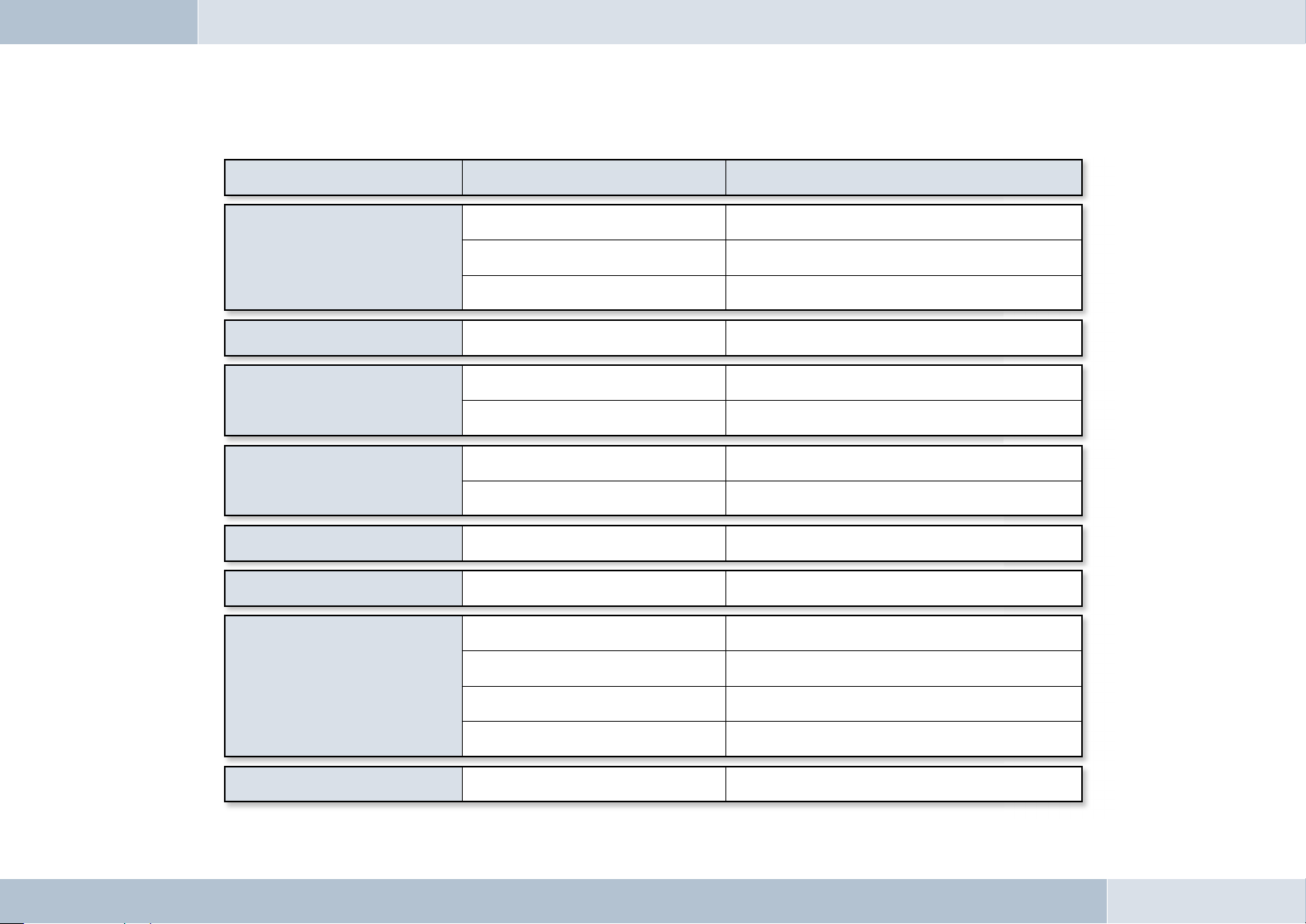
Troubleshooting:
Problem Cause Remedy
No supply voltage Replace fuse if needed and check cable and connections
EGO LOOK won’t switch on
Ignition not switched on Switch on ignition
Ignition line inter rupted Check line and 1A fuse
The person you are having a phone
conversation with cannot hear you
The person you are
having a phone conversation
with complains of interference
The person you are
having a phone conversation
The microphone is not plugged in
Air is fl owing across the microphone
The mobile phone is very close to
parts of the EGO LOOK or the car r adio
Too little space between
the microphone and speaker
with complains of echoes
The mobile phone cannot
fi nd the EGO LOOK during coupling
EGO LOOK is already coupled with a device Cancel existing connection
Sound is fuzzy or scratchy Poor Bluetooth
The mobile phone is not within range. Place the mobile phone within the r ange of the EGO LOOK
After switching on
the ignition, the connection
to the coupled mobile phone
is not produced.
The Bluetooth
deactivated in the mobile phone.
The mobile phone requires
confi rmation of the connection setup.
One of the devices no longer has a valid link key.
Connect the microphone to the electronics box. If the
cable is defecti ve, replacement is necessar y
Mount the microphone in another place or
reduce air fl ow if needed
Increase the distance between your mobile
phone and the EGO LOOK or radio
Increase distance or decrease volume
Volume too high Reduce volume
®
connection
®
interface is
Reduce the distance between the mobile phone and
EGO LOOK or remove (metallic) obstructions if needed
Switch your mobile phone’s Bluetooth
to "On" ("Automatic" option is not suffi cient)
Confi rm the connection on the mobile phone. Deactivate the
security prompt (see operating instructions for the mobile phone)
Delete the other device from both devices’
list of coupled devices and perform a new coupling.
®
No reac tion to user input
System frozen
(not responding)
Press the reset button on the back of the display using a
thin object (e.g. a paper clip). T he system restar ts.
54 | 55
Page 56

10
Accessories and spares parts
You can fi nd out more about supported mobile phones on our website at www.fwd-online.de. Your dealer will also be happy
to advise you if you have any questions.
Accessories:
Stereo Mute Box
Relax and listen to music or phone from your car. The Stereo Mute
Box provides smart sound management. This compact box plays your calls
or music over the car‘s speakers – of course in superb stereo sound. The
car radio is muted during calls or when listening to music.
Features:
- Radio muting during calls or music playback (Audio Streaming)
- Stereo music reproduction in combination with the car‘s front speakers
- Phone audio over the front speakers
Base plate with charging cradle
The charging cradle is a practical accessory for Bluetooth® hands-free
systems by Funkwerk Dabendorf. The charging cradle holds your mobile
phone fi rmly and allows you to recharge its batteries in your car and is
an ideal accessory for drivers who are constantly on the road and often
need their phones. In addition, the external antenna connection ensures
outstanding reception and transmission.
EGO LOOK
Features:
- Intelligent charging circuit for mobile phones
- Mobile phone safely and securely held in the charging cradle
- External antenna connection for excellent call quality
Page 57

Replacement parts:
FFF
[1] Electronics box
[2] Display
[3] Controller
[4] Microphone
[5] Set of connecting cables
[6] Adapter cable
52
T-Mobile
FWD
[1]
[5]
[2]
[3]
[4]
[6]
56 | 57
Page 58
11
Technical specifi cations
Outer dimensions of the electronics box 5.138 in x 2.126 in x 0.886 in
External dimensions: Display without base 3.039 in x 3.039 in x 0.906 in
External dimensions: Controller 1.843 in x 1.843 in x 1.244 in
Control unit cable lengths 6,56 ft
Operating voltage 11 V to 15 V
Quiescent current consumption (ignition off) max. 0.1 mA
Steady plus fuse protection 2 A
Ignition fuse protection 1 A
Temperature range -10°C to +55°C
Interfaces Microphone connection, line in, line out, accessory port, power supply
terminal and charging connection
Supports Bluetooth® profi les Hands-free, A2DP, AVRCP
EGO LOOK
12
Certifi cation
0681
Fully compliant with the EU R&TTE Directive 1999/5/EC
03 5074
Model certifi cation according to EU Directive 72/245/EWG (2006/28/EC) “Electromagnetic compatibility in motor vehicles”
®
Bluetooth® is a registered brand name of Bluetooth SIG, Inc.
Page 59

13
Conformity statement
This equipment employs Bluetooth® wireless technology. In some countries, the use of this equipment may be restricted
or forbidden. Please make sure you are familiar with such restrictions and do not use your equipment if you are unsure
whether its use is permitted in particular countries you may be visiting.
Bluetooth® is a registered brand name of Bluetooth SIG, Inc.
Funkwerk Dabendorf GmbH
Märkische Straße
D-15806 Dabendorf
Confi rms that the hands-free system “EGO LOOK” complies with the fundamental
requirements and other relevant regulations of the EU Directive 1999/5/EC.
0681
FCC / IC statements
This device complies with part 15 of the FCC Rules. Operation is subject to the following two conditions: (1) This device may not
cause harmful interference, and (2) this device must accept any interference received, including interference that may cause
undesired operation.
q
NOTE: This equipment has been tested and found to comply with the limits for a Class B digital device, pursuant to Part 15
of the FCC Rules. These limits are designed to provide reasonable protection against harmful interference in a residential
installation. This equipment generates, uses and can radiate radio frequency energy and, if not installed and used in
accordance with the instructions, may cause harmful interference to radio communications. However, there is no guarantee
that interference will not occur in a particular installation. If this equipment does cause harmful interference to radio or
television reception, which can be determined by turning the equipment off and on, the user is encouraged to try to correct the
interference by one or more of the following measures:
58 | 59
Page 60

→ Reorient or relocate the receiving antenna.
→ Increase the separation between the equipment and receiver.
→ Connect the equipment into an outlet on a circuit different from that to which the receiver is connected.
→ Consult the dealer or an experienced radio/TV technician for help.
q
q
q
WARNING: Changes or modifi cations made to this equipment not expressly approved by FWD may void the FCC authorization
to operate this equipment.
FCC Radiation Exposure statement:
This equipment complies with FCC radiation exposure limits set forth for an uncontrolled environment. End users must follow
the specifi c operating instructions for satisfying RF exposure compliance.
This transmitter must not be co-located or operating in conjunction with any other antenna or transmitter.
FCC / IC statements for radio controller „FwD FBT“
The labels for the radio controller according to FCC / IC can be found inside the battery lid.
NOTICE: This device complies with Part 15 of the FCC Rules [and with RSS-210 of Industry Canada]. Operation is subject to
the following two conditions:
(1) this device may not cause harmful interference, and
(2) this device must accept any interference received, including interference that may cause undesired operation.
NOTICE: Changes or modifi cations made to this equipment not expressly approved by Funkwerk Dabendorf may void the
FCC authorization to operate this equipment.
EGO LOOK
q
NOTICE: This Class A digital apparatus complies with Canadian ICES-003.
Page 61

14
Hotline
Any questions, comments, or suggestions? Would you like some more detailed information? Do you need an adviser or
service in your area? Just give us a call!
Our service hotline is there to help you during the following times:
Monday–Friday from 8.00 a.m. to 5.00 p.m. (PST)
Before you call us with your problem, please check fi rst with the following steps:
→ Check whether you can solve your problem with the „Troubleshooting“ checklist in Chapter 9.
→ Make sure you have your hands-free system and holder set type available.
→ Try to explain your problem as precisely as possible.
You can contact our service hotline by dialing:
Phone: (+1) 858.566.2170
Fax: (+1) 858.566.2179
eMail support@egohandsfree.com
60 | 61
Page 62

RAYTEL Corporation
A partner of Funkwerk Dabendorf GmbH
8820 Kenamar Drive, Ste 506
San Diego, CA 92121
Telephone (+1) 858.566.2159
Fax (+1) 858.566.2179
eMail support@egohandsfree.com
Internet www.egohandsfree.com
Funkwerk Dabendorf reserves the right to modifi cations in the course of technological progress and deviations from the delivery scope! All rights reserved!
Reproduction, in whole or in part, is only permitted with the prior written consent of Funkwerk Dabendorf GmbH!
A Funkwerk AG company
 Loading...