

Page 1
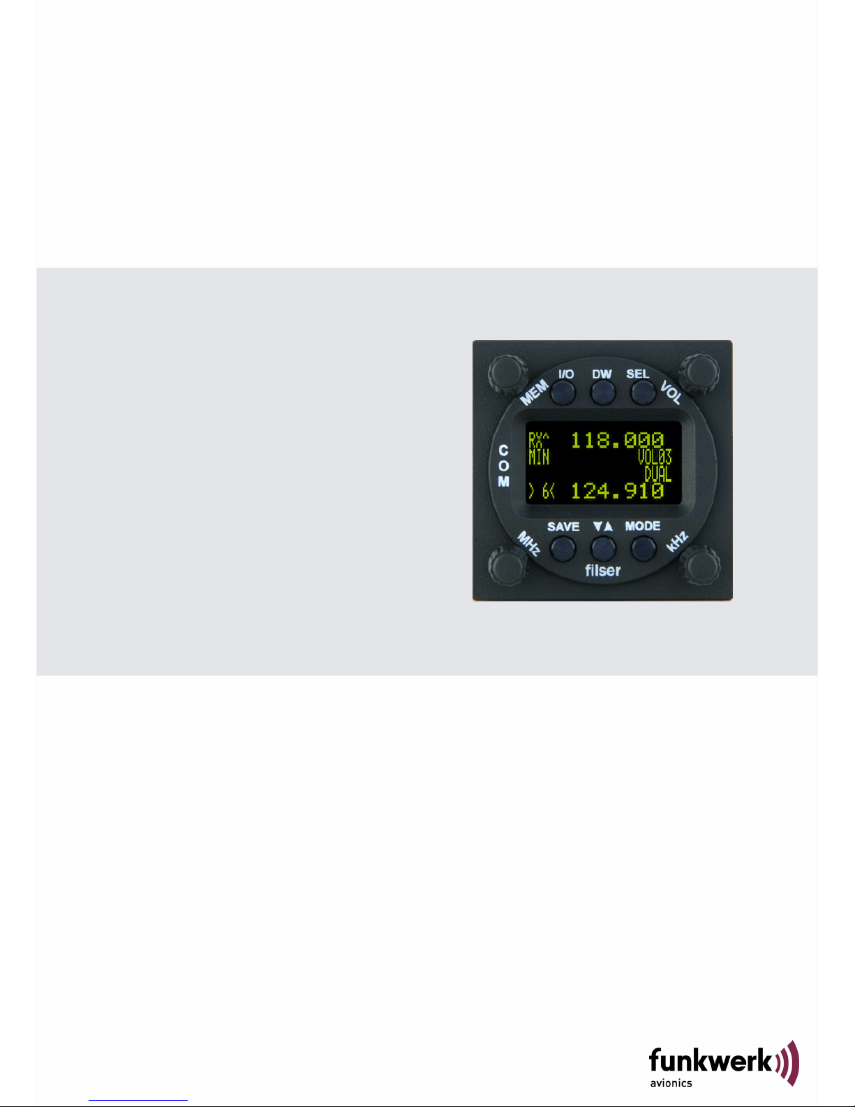
A
TR833 - OLED
VHF Communication
Transceiver
P/N 833-(1xx)-(1xx)
Operation and Installation
(Document-No. 01.1402.010.71e)
Page 2

ATR833 / P/N 833-(1xx)-(1xx)
Operation and Installation
Change History
Revision Date Description of Change
1.00 11.08.2009 FAV – First Release
1.01 15.10.2009 Changed order of Basic Settings (SW5.6)
List of the Service Bulletins (SB)
Services bulletins are to be inserted in the manual and to be put down
in this table.
SB Number
Rev.
No.
Issue Date Entry Date Name
Survey of Variants
Part Number Description
P/N 833(000)-(000) Base Variation
P/N 833(100)-(100) Introduction from:
• 2 standards of microphone inputs
• To 2 dynamic microphone inputs
• Additional audio input
• DUAL Watch function
P/N 833(101)-(101) LC Display replaced by OLED Display
P/N 833(103)-(101) SW V5.5 new operating functions:
Master Reset
Æ Factory Settings
Energy Saving Mode
Æ Display Darkening
2 Dokument-Nr.: 01.1402.010.71e / Revision: 1.01
Page 3

ATR833 / P/N 833-(1xx)-(1xx)
Operation and Installation
Contents
1 General ..............................................................................................5
1.1 Symbols ...................................................................................5
1.2 Abbreviations ...........................................................................5
1.3 Customer Support ....................................................................6
1.4 Features ................................................................................... 6
2 Operation ...........................................................................................7
2.1 Controls....................................................................................7
2.2 ON/OFF.................................................................................... 9
2.3 Display .....................................................................................9
2.4 Basic Settings ........................................................................11
2.4.1 VOL – Volume .............................................................12
2.4.2 SQ – Squelch ..............................................................12
2.4.3 VOX – Voice Detection (Intercom Function)................13
2.4.4 DIM – Display Brightness ............................................13
2.4.5 INT – Intercom-Volume ...............................................14
2.4.6 EXT – Volume of the external Audio-entrance ............ 14
2.4.7 TXm – Activation of the PTT-buttons...........................14
2.5 Frequency Settings ................................................................15
2.5.1 Manual Input................................................................ 15
2.5.2 Select frequency from memory position ...................... 15
2.5.3 Select frequency from the frequency database........... 15
2.5.4 Editing of the User-Defined frequency list ...................16
2.5.5 DUAL Watch................................................................ 18
2.6 Transmission..........................................................................19
2.7 Reception ...............................................................................19
2.8 Enhanced Settings .................................................................20
2.8.1 Energy Saving Mode – Darkening the Display ............ 20
2.8.2 Master Reset - Set back to factory settings.................20
2.8.3 SET UP - Menu ...........................................................21
2.8.4 MIC – Settings.............................................................22
2.8.5 Test Mode ...................................................................23
2.9 Managing the Database .........................................................24
2.9.1 Transfer of the general frequency database................25
3Dokument-Nr.: 01.1402.010.71e / Revision: 1.01
Page 4

ATR833 / P/N 833-(1xx)-(1xx)
Operation and Installation
2.9.2 Transfer of the user-defined frequency list..................26
2.10 Remote Control Panel ............................................................ 27
3 Installation ........................................................................................ 28
3.1 Advices and Tips....................................................................28
3.2 Telecommunication Data .......................................................28
3.3 Scope of delivery.................................................................... 28
3.4 Unpacking and Inspecting the Equipment.............................. 29
3.5 Mounting ................................................................................29
3.6 Equipment Connections .........................................................30
3.6.1 Microphone-Connection ..............................................30
3.6.2 Headset-Connection.................................................... 30
3.6.3 Audio-Input ..................................................................31
3.7 Wiring ..................................................................................... 31
3.7.1 Conductor Cross Section.............................................31
3.7.2 Connector – Pin Allocation ..........................................31
3.7.3 Wiring Diagram............................................................ 32
3.8 Antenna..................................................................................33
3.8.1 Antenna Selection .......................................................33
3.8.2 Installation Recommendation ......................................33
3.9 Microphone Settings ..............................................................34
3.10 Post-Installation Check .......................................................... 34
3.11 Starting up .............................................................................. 35
3.12 Accessories ............................................................................ 35
3.13 Drawings ................................................................................36
3.13.1 Dimensions.................................................................. 36
3.13.2 Mounting Advices ........................................................36
4 APPENDIX ....................................................................................... 37
4.1 Frequency/Channel-Plan .......................................................37
4.2 Technical Data ....................................................................... 38
4.3 Environmental Conditions ......................................................40
4 Dokument-Nr.: 01.1402.010.71e / Revision: 1.01
Page 5

ATR833 / P/N 833-(1xx)-(1xx)
Operation and Installation
1 GENERAL
This manual contains information about the physical, mechanical and
electrical characteristics as well as information about installation and
operation of the aeronautical radio device VHF ATR833.
1.1 Symbols
Advices whose non-observance can cause radiation
damage to the human body or ignition of combustible
materials.
Advices whose non-observance can cause damage to the
device or other parts of the equipment.
Information
1.2 Abbreviations
Abb. Name/subject Definition
PTT Push to Talk activates transmitter
VOX Voice Recognition Intercom is activated by talking
INT Intercom On board communication
SQ Squelch
DIM Dimming Display Brightness
EXT External audio input
5Dokument-Nr.: 01.1402.010.71e / Revision: 1.01
Page 6
ATR833 / P/N 833-(1xx)-(1xx)
Operation and Installation
1.3 Customer Support
In order to facilitate a rapid return of shipments, please follow the
instructions of the input guide “Reshipment RMA” provided at the
Service-Area within the Funkwerk Avionics web portal
www.funkwerk-
avionics.com.
Any suggestions for improvement of our manuals are
welcome. Contact:
service@funkwerk-avionics.com.
Informations on software updates are available at Funkwerk
Avionics.
1.4 Features
• VHF communication transceiver for aircraft installation
• frequency range118,000 to 136,975 MHz
• channel spacing 8,33/25 kHz (2278/760 canals)
• 4 microphone inputs (2 x standard, 2 x dynamic)
• auxiliary audio input
• mounting: 57 mm cut out
• 100 user defined frequencies which can be titled with a name up to
8 characters
• frequency database with 5896 entries – selection of entries by
input of the airfield name - update through serial interface frequencies of european airfields pre-installed.
To avoid unintentional permanent transmission, the
transmitter automatically stops transmission after two
Minutes of uninterrupted operation.
6 Dokument-Nr.: 01.1402.010.71e / Revision: 1.01
Page 7

ATR833 / P/N 833-(1xx)-(1xx)
Operation and Installation
2 OPERATION
2.1 Controls
CHANGE
Change
between
Standby and
active
frequency
De- /
Activate
dual mode
DW
Rotary knob
change of kHz
digits
Cursor position
during text input
Select from user-
defined frequency
memory
Rotary knob
Adjusting of
volume and VOX
threshold etc. …
Rotary knob
MODE
Switch
between normal
operation and
memory functions
(USER, DATA)
ON/OFF
Selection key for
adjusting VOL,
VOX, SQ, etc. …
SEL
Rotary knob
change MHz
digits
Selection of
letters during text
input
SAVE
Store
frequencies
7Dokument-Nr.: 01.1402.010.71e / Revision: 1.01
Page 8

ATR833 / P/N 833-(1xx)-(1xx)
Operation and Installation
ON/OFF
Switch On press button for approx. 0,5 s
Switch Off press button for approx. 3 s
DUAL
WATCH
Activates the mode for mutual interception
of two frequencies
CHOICE
1. Selection of the different pages of the
basic settings VOL, SQ, VOX, DIM etc.
Æpress button shortly
2. MIC settings Æ press button for 5
seconds
SAVE
Store the active frequency on the selected
memory position
(see section. 2.5.4 page 16)
CHANGE
Switch between Active and Standby
frequency
MODE
Switch between direct input mode (normal
operation) and memory administration
(frequency memories USER and DATA)
MEM –
Rotary
Knob
Rotary Knob for the selection of a stored
user-defined frequency
VOL –
Rotary
Knob
1. Setting of the volume (earphone,
loudspeaker)
2. Change of the basic settings, accessed
by
MHz –
Rotary
Knob
1. Change MHz digits of the Standby
frequency directly
2. Enter letters in the modes USER and
DATA
kHz –
Rotary
Knob
1. Change kHz digits of the Standby
frequency directly
2. Cursor positioning in the modes USER
and DATA
8 Dokument-Nr.: 01.1402.010.71e / Revision: 1.01
Page 9
ATR833 / P/N 833-(1xx)-(1xx)
Operation and Installation
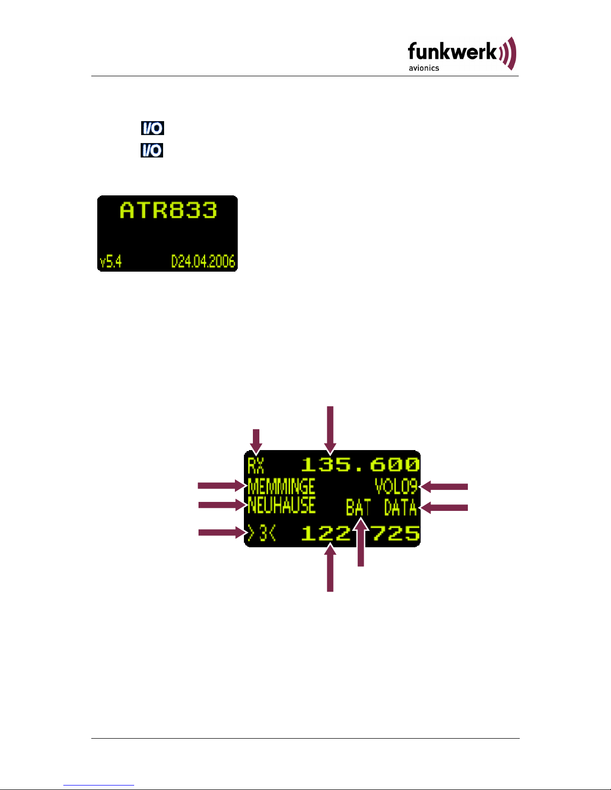
2.2 ON/OFF
ON: press button for 0.5 s
OFF:
press button for 3 s
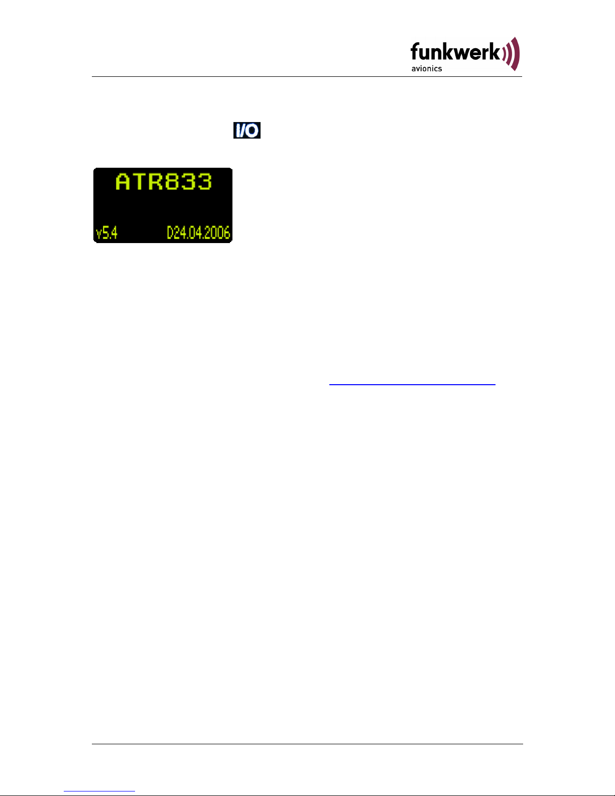
After turning-on the display appears as follows:
(Example)
Device Name
ATR833
Software-Version
e.g. v5.4
State of the frequency database (if loaded)
e.g. D24.04.2006
The radio device starts in normal mode (direct frequency input) under
use of the last settings.
2.3 Display
A
ctive Frequenc
y
Volume
etc.
Low Battery
Standby-Frequency
Operational Condition
(TX, RX, Te)
Active Station
Standby Station
Input
Mode
DATA,
USER
Memory Position
9Dokument-Nr.: 01.1402.010.71e / Revision: 1.01
Page 10

ATR833 / P/N 833-(1xx)-(1xx)
Operation and Installation
Display Meaning Remark
RX Operational Condition -
Reception
Indicates when reception
takes place. (Squelch
open)
TX Operational Condition -
Transmit
Transmitter works properly
Te Transmitter was
automatically switched off
after 2 min continuous
transmission
135.600 Active Frequency
MEMMINGE Name of the Active
Frequency
Assigned name in userdefined memory or
frequency database
VOL Volume Level (indicated by
default)
If SEL was pressed, at this
position the respective
values of the other basic
settings are indicated (see
2.4)
SQ Squelch
VOX Voice Detection Intercom controlled by
voice
DIM Display Brightness
INT Intercom - Volume
EXT Volume of external audio-
signals
TXm PTT-Button Selection Left/Right/Both
NEWHOUSE Name of the Standby
Frequency
Assigned naming in userdefined memory or
frequency database
BAT Low Battery
<10,5V
Possible defective battery
or generator
Er Internal failure/
transmission interrupted
Device must be sent back
to the manufacturer
10 Dokument-Nr.: 01.1402.010.71e / Revision: 1.01
Page 11

ATR833 / P/N 833-(1xx)-(1xx)
Operation and Installation
Display Meaning Remark
DATA Access to frequency
database active
Selectable with
Access to Database is
Read Only, Search entries
by input of airfield name
USER Define and Store entries in
the user-defined frequency
list (0-99)
Selectable with
store the StandbyFrequency at the currently
selected memory position
(see 2.5.4)
DUAL DUAL Watch is activated Activated by (2.5.5)
>3< Selected Memory Position
(appearance of brackets
shows whether the
standby frequency and
stored information comply)
[ ] selected storage space
in the user-defined
frequency list (0-99)
<> frequency does not
comply with the stored one.
122.725 Standby - Frequency
2.4 Basic Settings
Between the different menu points of the basic settings can be switched
with the
button.
0. VOL .... Volume
1. SQ ...... Squelch
2. VOX.... Configuration of the threshold value to activate Intercom
3. DIM..... Display Brightness
4. INT ..... Intercom-Volume
5. EXT .... Volume of external audio-signals
6. TXm.... PTT-Key Choice (Left/Right/Both)
7. Back to Frequency Setting
The settings of the volume can be controlled by the
rotary knob.
The return to the standard display (VOL) works automatically after 6
seconds or can be reached by pressing the
button several times.
11Dokument-Nr.: 01.1402.010.71e / Revision: 1.01
Page 12

ATR833 / P/N 833-(1xx)-(1xx)
Operation and Installation
2.4.1 VOL – Volume
Normally (not necessarily selected with the
button) with the rotation
of the
key, the reception volume can be adjusted.
Range: 01 - 16
The VOL-Setting does only affect the received signal, not the
Intercom level, which is pre-configured by factory.
2.4.2 SQ – Squelch
By pressing the
key once, with the help of the rotary knob
Squelch can be adjusted.
Range: 01 - 10
The setting for the Squelch is dependent on different factors. For motor
aircrafts an initial setting of 7-8 applies, gliders may use settings below
that value. A high number reflects a high input sensitivity and may result
in disturbances from different sources (engine, strobe lights).
The default Squelch setting is 07 ... 08. Higher values could
suppress weak signals. Squelch does not impact the
Intercom.
12 Dokument-Nr.: 01.1402.010.71e / Revision: 1.01
Page 13

ATR833 / P/N 833-(1xx)-(1xx)
Operation and Installation
2.4.3 VOX – Voice Detection (Intercom Function)
By pressing the
key twice, with the help of the rotary knob, the
threshold value for voice detection can be adjusted.
VOX defines the volume threshold at which normal noise during flight is
not transferred into the headset. Only an additional voice signal activates
intercom operation.
The higher the value, the louder you need to speak in order to activate
the Intercom connection.
Range: 01 - 10
In case of a noisy background or uncompensated microphones it is
possible to deactivate VOX with VOX: 01. If done so, Intercom is enabled
by use of the Intercom-Switch.
In order to configure the microphone sensitivity (see 2.8.4)
VOX should be set to VOX: 05, allowing further adjustments
during flight.
2.4.4 DIM – Display Brightness
By pressing the
key six times, with help from the rotary knob,
the strength of the background illumination of the display can be set.
Range: 01 - 10
13Dokument-Nr.: 01.1402.010.71e / Revision: 1.01
Page 14

ATR833 / P/N 833-(1xx)-(1xx)
Operation and Installation
2.4.5 INT – Intercom-Volume
By pressing the
key four times, with help from the rotary knob
the Intercom Volume level can be controlled.
Range: 01 - 10
2.4.6 EXT – Volume of the external Audio-entrance
By pressing the
key five times, with help from the rotary knob,
the volume from the connected external audio signals (Warning tone,
music, etc…) can be set.
Range: 00 - 10
2.4.7 TXm – Activation of the PTT-buttons
By pressing the
key three times, with the help of the rotary
knob, the PTT-buttons can be selected.
*
- Left / -
*
Right / ** Both
14 Dokument-Nr.: 01.1402.010.71e / Revision: 1.01
Page 15

ATR833 / P/N 833-(1xx)-(1xx)
Operation and Installation
2.5 Frequency Settings
The input of a frequency can be done in three different ways, by:
• Direct/manual input (with the lower rotary knobs for the
and
Range).
• Selection from the user-defined frequency list (Memory Positions 0-99)
with the
rotary knob.
• Selection from the frequency database (if loaded) in the DATA-Mode
Between these input modes, it can be switched with the
key. The
currently active mode is indicated on the third line on the right.
• No indication..... direct input with
and or selection from the
user-defined frequency list with
• USER................ no frequency selection only Edit and Storing in the
user-defined frequency list.
• DATA ................ Search in the frequency database (if loaded)
2.5.1 Manual Input
The frequency can be set with the
and rotary knobs. It is
indicated as Standby-Frequency in the lower line.
During the input the existing name (left on the third line) is overwritten.
The indication of the memory position (format of the brackets) changes
from [xx] in >xx<, showing that the new Standby-Frequency does not
comply with the contents of the indicated frequency memory position.
switches active and standby-frequencies.
2.5.2 Select frequency from memory position
With
, a stored frequency can be selected from the user-defined
frequency.
In this case the respective memory position [xx] (xx =
becomes 0 … 99) as well as the frequency name and the stored
frequency are indicated.
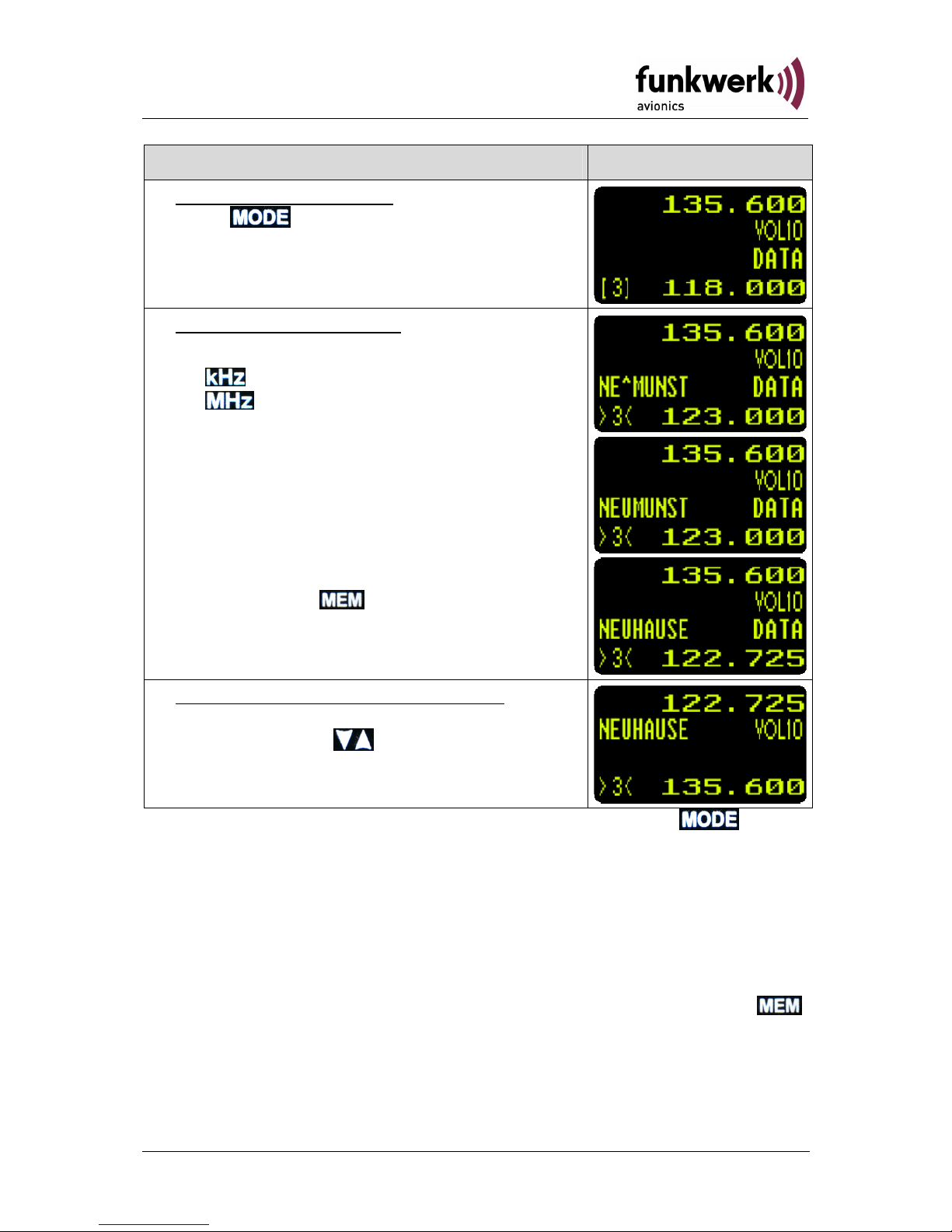
2.5.3 Select frequency from the frequency database
This function is available only with installed frequency database.
15Dokument-Nr.: 01.1402.010.71e / Revision: 1.01
Page 16
ATR833 / P/N 833-(1xx)-(1xx)
Operation and Installation
Step Display (Example)
1. Change to DATA mode:
press
until DATA appears on the right
in the third line.
2. Searching the Database:
a. Input the first letters of the desired station
... positions the cursor
. selects the letters
at the position of the cursor the cursor symbol
“^“and the chosen letters blink alternately
b. The first found entry which fits the search
criteria is displayed with its name and the
belonging frequency.
c. The selection of other, also fitting entries
is done with
3. Activation of the selected frequency:
Once the desired frequency is found, it can
be activated with
. The device changes
back to the direct input mode.
The database search can be canceled at anytime with the button.
The selected frequency remains as the standby-frequency.
2.5.4 Editing of the User-Defined frequency list
The Standby frequency given in the lower line can be named and stored
in the user's list (user-defined frequency list).
Before saving, the desired memory position must be chosen in the direct
input mode (the third line indicates neither USER nor DATA) with
.
The currently stored entry will be overwritten.
16 Dokument-Nr.: 01.1402.010.71e / Revision: 1.01
Page 17
ATR833 / P/N 833-(1xx)-(1xx)
Operation and Installation
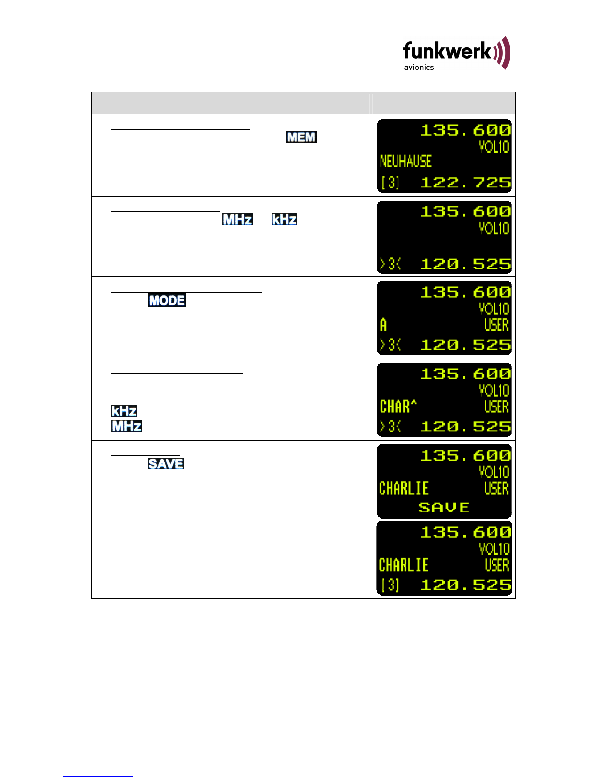
Step Display (Example)
1. Select memory position:
In the direct input mode press
to select
a memory position. The current entry is now
indicated with frequency and the respective
designator.
2. Setting Frequency:
a) Direct input with
or
b) select frequency in DATA-Mode (see
2.5.3)
3. Change into USER-Mode:
Press
to enter USER-Mode
“USER“ is displayed (third line on the right).
4. Enter frequency name:
The input of the user-defined designator is
done with the lower rotary knobs.
...... positions the Cursor
.... selects the letters
5. Store Entry:
Press
to store the chosen frequency
with the defined name on the indicated
memory position. In the lower line „SAVE“
appears for 2 seconds, after that the device
changes back into the direct input mode.
17Dokument-Nr.: 01.1402.010.71e / Revision: 1.01
Page 18
ATR833 / P/N 833-(1xx)-(1xx)
Operation and Installation
2.5.5 DUAL Watch
The ATR833 owns
one receiver, therefore, DUAL-Watch (listen to two
frequencies) happens alternately between the active and the standby
frequency.
By pressing the
key DUAL Watch is activated, pressing again
deactivates it.
The two frequencies, the receiver shall alternately listen to, should be
entered before activating DUAL Watch, since changes in the standby
frequency would deactivate this mode again.
Another important precondition is the setting of the Squelch value (SQ).
It must at least be set to SQ: 02 (SQ-setting see 2.4.2). Only if a noise
suppression takes place, it can be evaluated whether nothing is received
on the active frequency.
SQ must be set to a value that is is at least 02, because
otherwise no noise reduction would happen, in this case it
would not be possible to determine if a reception takes place
or not.
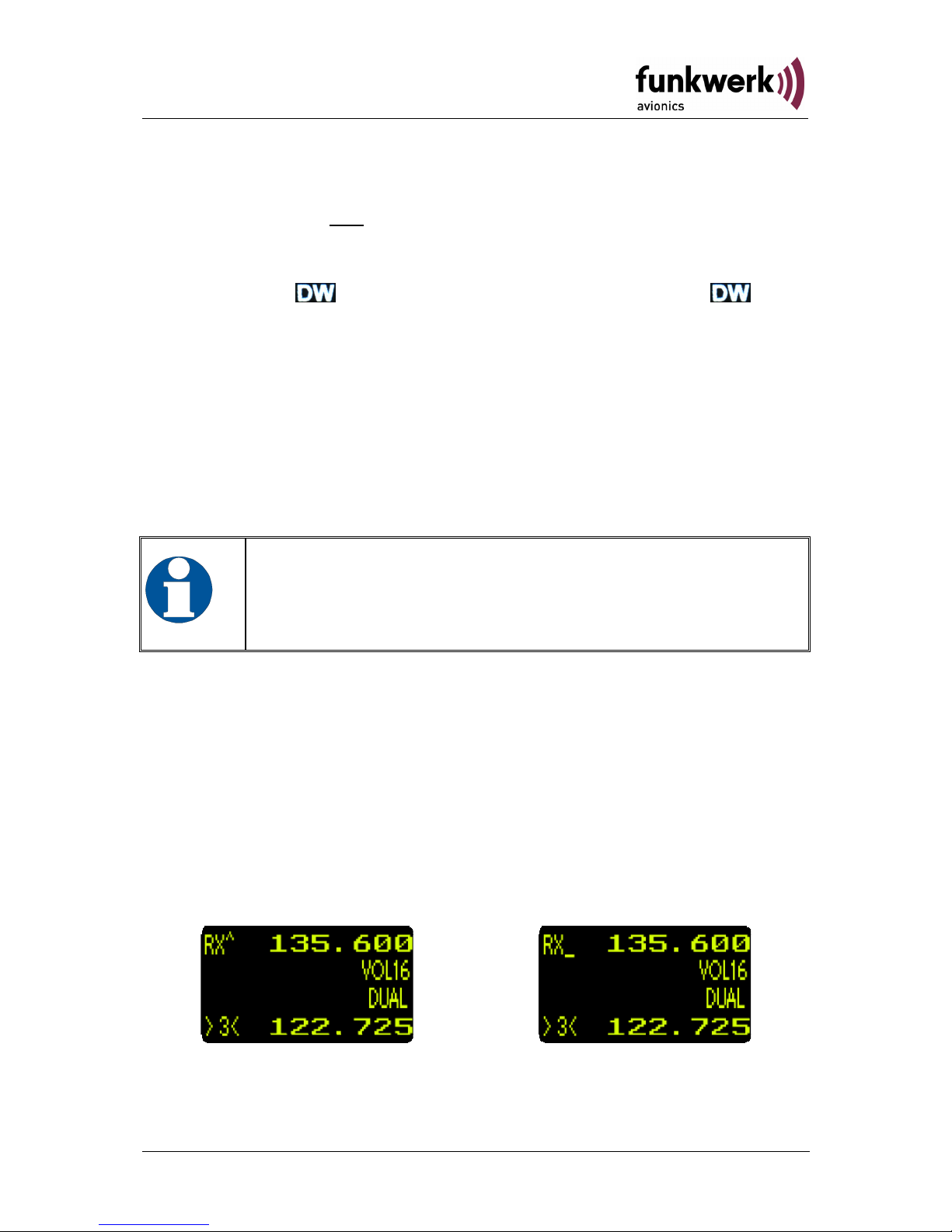
When the DUAL Watch is activated, DUAL will be shown in the third line.
When there is no reception on the active frequency, the receiver
switches to the standby frequency. The active frequency has priority and
it is monitored every 2 seconds for a duration of 0.3 seconds. If reception
on the active frequency is recognized again, the monitoring of the
standby frequency is interrupted until no reception takes place on the
active frequency.
Which frequency is currently monitored will be shown behind RX: “RX^“
” if the active frequency is monitored and “RX_“ ” if the StandbyFrequency is monitored.
In DUAL Watch Mode it is possible to switch between the standbyfrequency and the active frequency. Transmission is always done on the
active frequency.
18 Dokument-Nr.: 01.1402.010.71e / Revision: 1.01
Page 19
ATR833 / P/N 833-(1xx)-(1xx)
Operation and Installation
Quick approach:
• Select or enter a Standby-Frequency, which should be additionally
monitored.
• Set SQ with the
key and the rotary knob to a value of at
least 02.
• Activate DUAL Watch with
(DUAL is shown)
• As soon as no reception is determined on the activate frequency,
the mutual monitoring between active and Standby-Frequency
starts (2 seconds Standby and 0.3 seconds active frequency)
• In order to deactivate DUAL Watch: press
once more or change
the frequency.
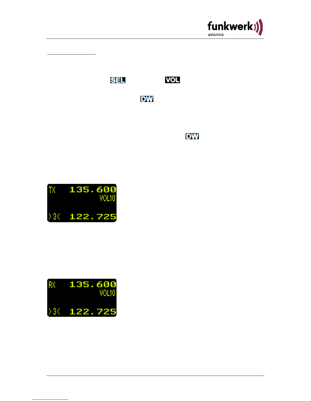
2.6 Transmission
By pushing the PTT button, the device starts transmission on the
selected frequency (shown in the upper line).
“TX“ indicates correct operation of the transmitter.
In order to avoid unintended transmissions, the transmitter stops after
two minutes and the display changes from „TX“ to „Te“. In order to restart transmission, release PTT and push it again.
2.7 Reception
While receiving (squelch is open) “RX” is shown.
19Dokument-Nr.: 01.1402.010.71e / Revision: 1.01
Page 20
ATR833 / P/N 833-(1xx)-(1xx)
Operation and Installation
2.8 Enhanced Settings
In the following section configurations beyond the basic settings are
explained.
In order to save energy and to extent lifetime of the OLED Display an
automatic Darkening of the Display “ENERGY SAVING MODE“ can
be configured.
The Master Reset - Function sets the user settings back to the factory
settings.
In the SET UP - Menu the frequency databases (including the userdefined frequency list) can be deleted and the channel spacing can be
configured.
In the MIC - Settings the microphone sensitivity is configurable.
+ Turning on
Energy Saving Mode
+ +Turning on
Master Reset (Factory Settings)
+ Turning on SET-UP Menu
Press longer than 5 seconds
MIC - Settings
2.8.1 Energy Saving Mode – Darkening the Display
Available since P/N 833-(103)-(101) software version V5.5
The Energy Saving Mode - Menu can be accessed by pressing the
key and the key simultaneously.
With the
rotary knob a time span can be defined, after which the
display automatically darkens if no key or rotary knob was in use. The
time span can be set up to 30 minutes. The automatic darkening can be
deactivated with selecting the “Never“ option (default). By pressing the
key again, the setting is saved and the menu is left.
2.8.2 Master Reset - Set back to factory settings
Available since P/N 833-(103)-(101) software version V5.5
The factory settings can be reset only from the switched-off device. In
order to reset to factory settings press the
key (to switch on), the
key and the key simultaneously. The display shows
“SETTING RESTORE“. After releasing the keys the settings are reset to
the factory settings. This will be confirmed by the message,
“SUCCESSFULLY“.
20 Dokument-Nr.: 01.1402.010.71e / Revision: 1.01
Page 21
ATR833 / P/N 833-(1xx)-(1xx)
Operation and Installation
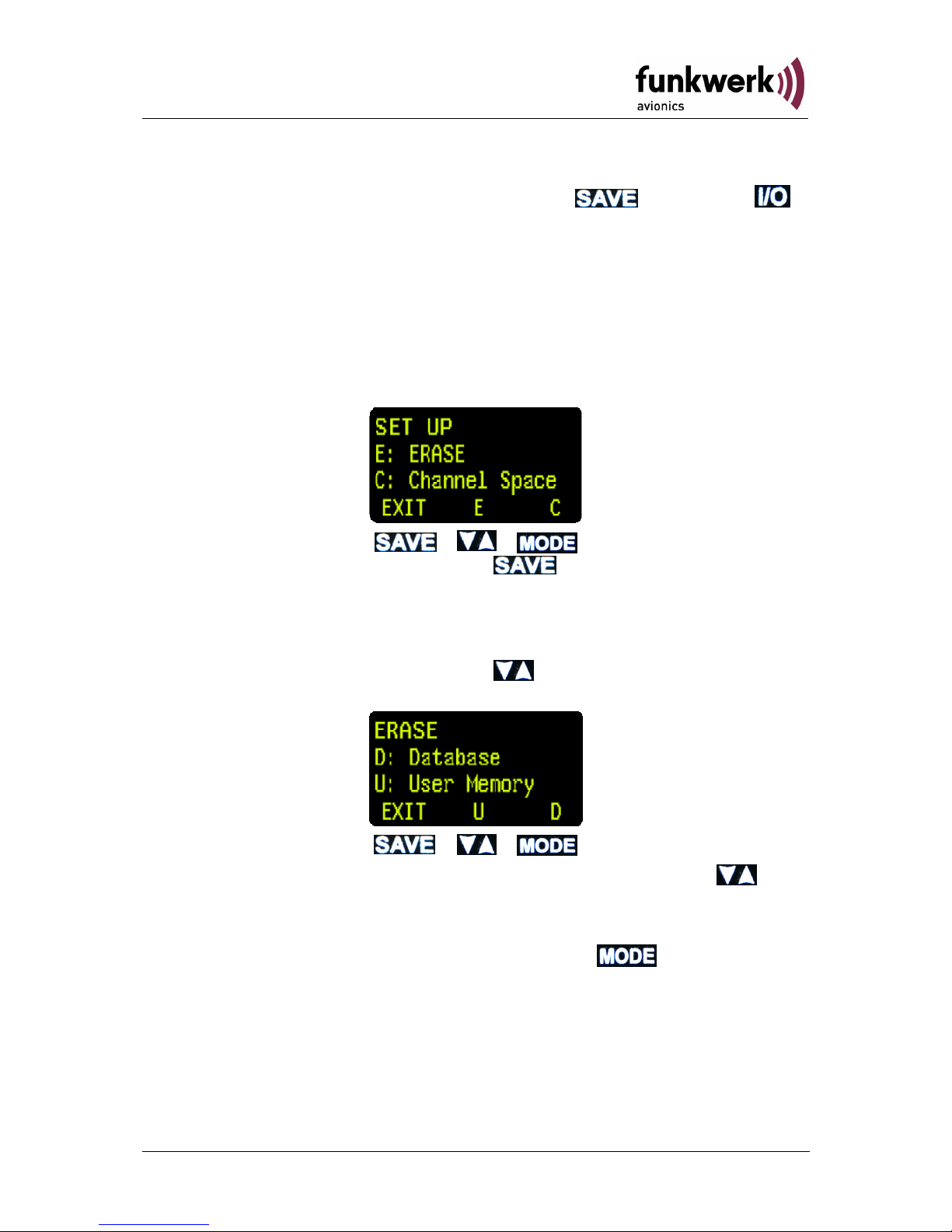
2.8.3 SET UP - Menu
The SET UP-Menu is activated by pressing the
key and the
key simultaneously
.
The following functions are available:
• ERASE – To delete data memories (USER, DATA)
• Channel Spacing–Setting of the channel spacing(25kHz / 8,33kHz)
The selection between the options of the SET UP-Menu is done with the
lower row of keys.
The SET UP-Menu is left with the
key. The device remains
switched-on and returns to the normal display mode.
2.8.3.1 ERASE – Delete the data memories
In the SET UP–Menu, by pressing the
key, the “ERASE“ menu
opens:
The erasing of the user-defined frequency can now be with the
keys. The process takes a few minutes and the display presents the
message: “ERASING“.
The Frequency Database can be deleted with the
key.
If the user-defined frequency list was deleted, the display shows “INIT---“ instead of the frequency names.
21Dokument-Nr.: 01.1402.010.71e / Revision: 1.01
Page 22
ATR833 / P/N 833-(1xx)-(1xx)
Operation and Installation
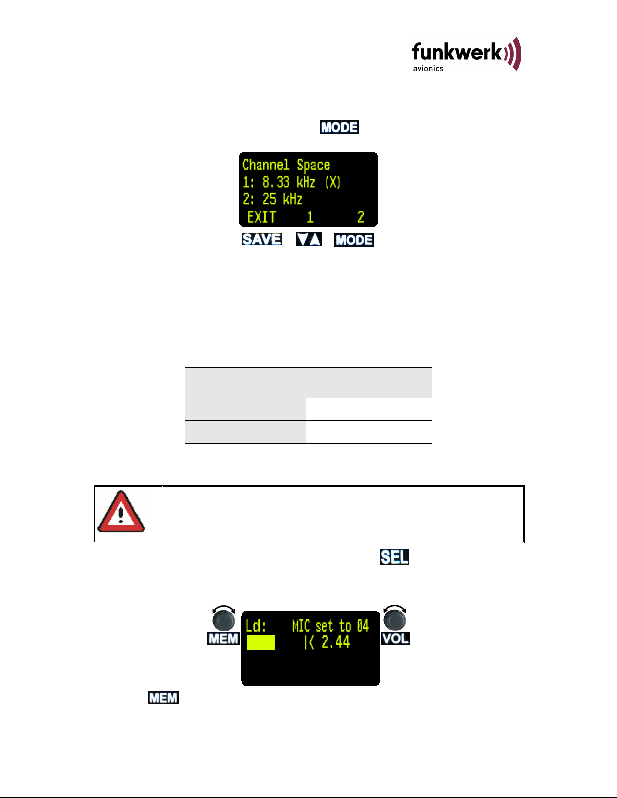
2.8.3.2 Channel Space
In the SET UP–Menu, by pressing the
key, the “Channel Space“
sub menu is opened:
This menu enables to select the desired channel spacing. The actual
channel spacing is marked with an “(X)“ at the end of the line.
2.8.4 MIC – Settings
Every microphone input can be individually configured. Therefore
different types of microphones can be used.
Microphone Input Left Right
standard Ls.MIC Rs.MIC
dynamic Ld.MIC Rd.MIC
Per microphone input a maximum of two parallel installed microphones
may be connected. (see 3.6.1)
The MIC-settings are opened by pressing the
key 5 seconds or
longer. A countdown will appear in the upper line on the left side. After
the countdown is finished the MIC-settings menu will be displayed.
For setting MIC, VOX must be set to 5 previously (for VOX Settings refer to section 2.4.3 page 12).
With the
rotary knob, the microphone is chosen (for example, “Ld“
for Left/dynamic).
22 Dokument-Nr.: 01.1402.010.71e / Revision: 1.01
Page 23
ATR833 / P/N 833-(1xx)-(1xx)
Operation and Installation
With the rotary knob, it is possible to configure the input sensitivity
of the preamplifier “MIC“ (01=insensitivity, 10=max. sensitivity), the so
adjusted microphone level is indicated below.
To correctly set the microphone level, it must be configured with a
running engine and speaking at a normal volume, while doing this the
microphone level should be set to approximately 2.00 (bar graph should
reach the middle of the scale)
With the
rotary knob, e.g. to configure another microphone, the
present settings are saved.
To save and to exit the menu press the
button.
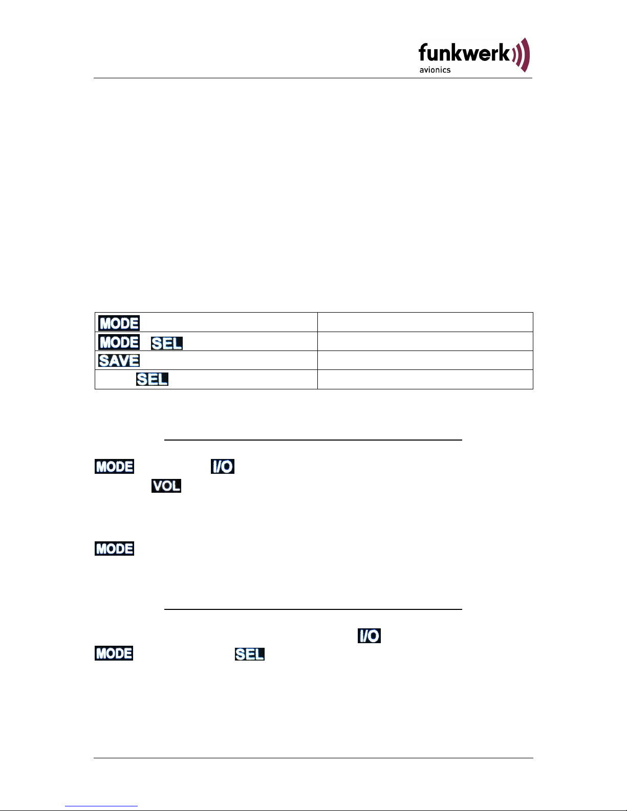
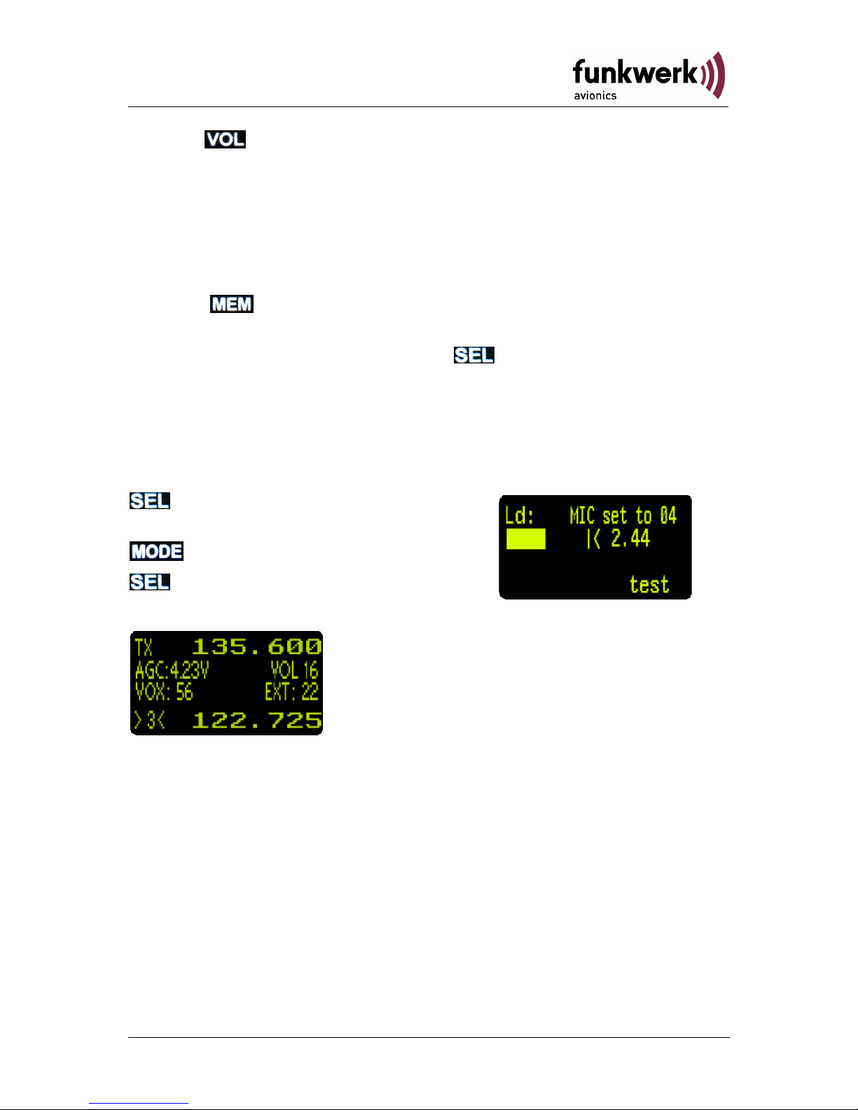
2.8.5 Test Mode
The Test-Modus is used for testing purposes. It is activated in the MICSettings menu (see 2.8.4). In order to reach the test mode from normal
operation:
press for 5 seconds
(MIC – setting turns on)
press shortly (“test“ appears)
press shortly, to leave the menu.
The test display will now appear:
Screen contents and meaning:
AGC:... receiver RF input level
VOX:... sum of the microphone input levels
Ext: ..... external audio input level
To exit test mode, restart the device.
23Dokument-Nr.: 01.1402.010.71e / Revision: 1.01
Page 24
ATR833 / P/N 833-(1xx)-(1xx)
Operation and Installation
2.9 Managing the Database
The user-defined frequency list (memory positions 0-99), as well as the
general frequency database can be edited and updated on a PC.
For that, a suitable cable set (with RS232 connector) as well as the
transfer software for PCs (Windows) are required.
The transfer software "General Programmer" can be downloaded from
www.funkwerk-avionics.com website, under SERVICEÆINFO as packed
file ("ATR_Programmer_v3.5"). The cable set (order no.:
ZATRPCKABEL) can be obtained in our online shop or from our
distributors.
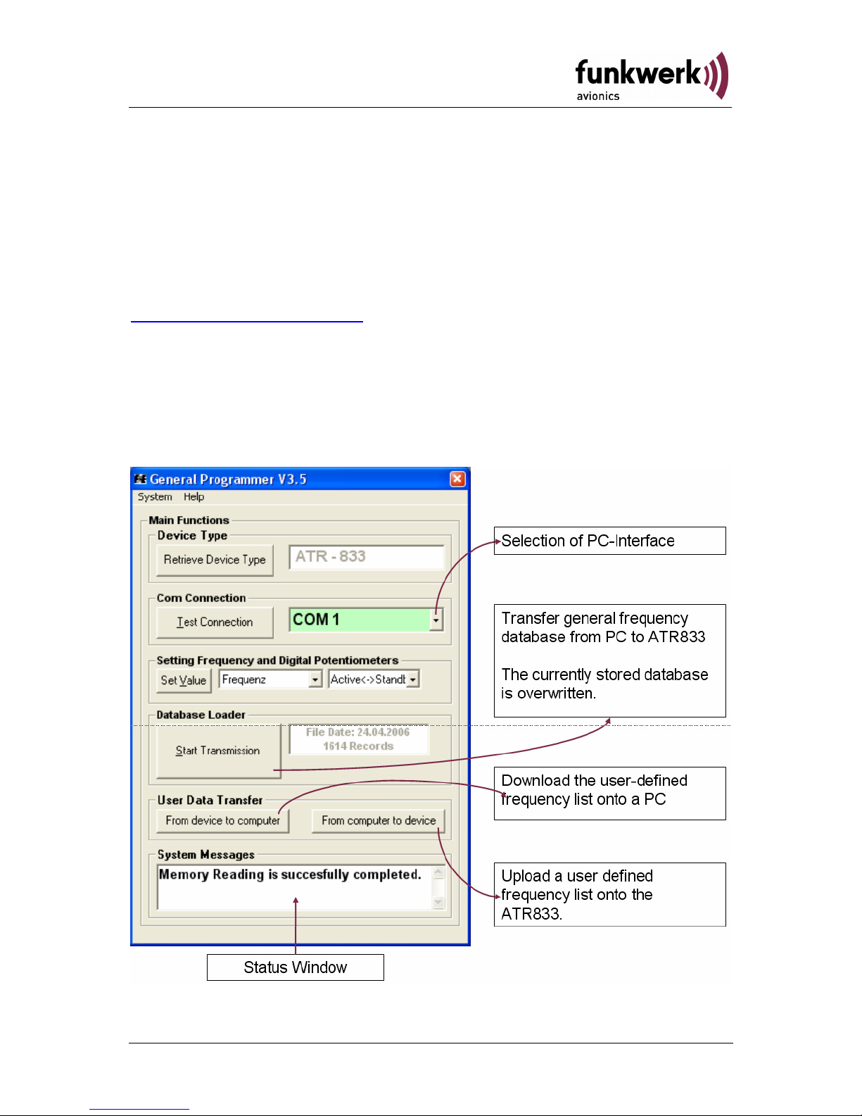
The transfer software must be unzipped and installed per setup.exe. If
the ATR833 is correctly connected while the software is started, the user
interface appears as follows:
24 Dokument-Nr.: 01.1402.010.71e / Revision: 1.01
Page 25
ATR833 / P/N 833-(1xx)-(1xx)
Operation and Installation
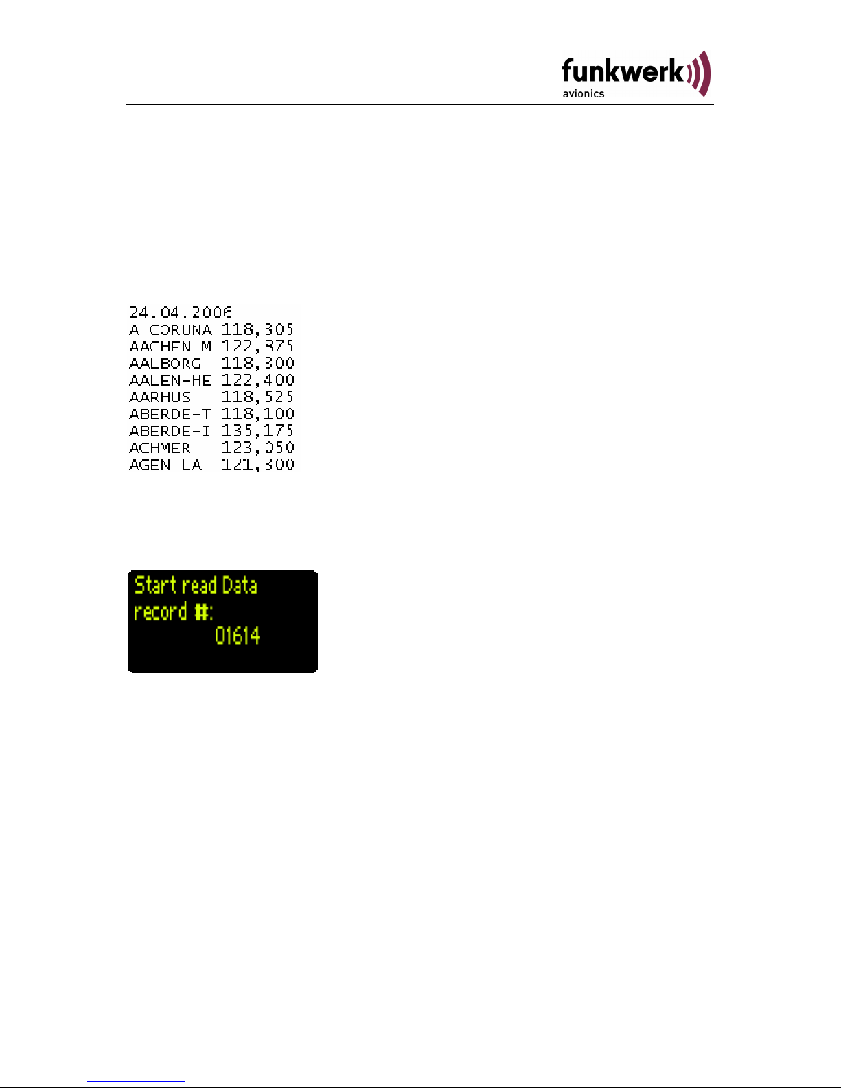
2.9.1 Transfer of the general frequency database
The general frequency database can be updated with "start of
transmission “. This overwrites the existing database..
The database file is a text file with fixed sized columns. The frequency
names shall never exceed the length of 8 characters. Blanks and
numbers are permitted. Frequency name and frequency are separated
by a blank.
After selecting “Start Transmission” the selection of the input file is
requested. After selection of the corresponding file and confirmation the
file transfer starts. The progress can be monitored on the ATR833
display:
While the transfer of the general database is only possible in one
direction (PCÆATR833), the user-defined frequency list of the ATR833
can be downloaded and uploaded (after modification) again.
25Dokument-Nr.: 01.1402.010.71e / Revision: 1.01
Page 26

ATR833 / P/N 833-(1xx)-(1xx)
Operation and Installation
2.9.2 Transfer of the user-defined frequency list
While transferring a file onto the ATR833, pay attention to the file name
which should be "User_Area.txt". Furthermore the contained data must
follow the suitable format (see following extract).
“Name5678“,“MHz“,“kHz“, Memory Position (0-99)
The datasets are transferred in
the order as they are given by
the file’s content. Hence, row 1
corresponds to memory position
0 and row 100 corresponds to
memory position 99. The
datasets should be sorted before
the upload, for that the number
at the end of the row may be
modified in order to re-arrange
the sequence fitting individual
needs.
In order to avoid errors due to a
wrong list format, it is
recommended to download the
“User-Area.txt” file and to modify
this downloaded file.
By selecting the button „From device to
computer“ the “User_Area.txt” file is
downloaded in the program root or in the last
opened directory. The transfer progress can be
monitored on the ATR833 display:
For uploading a file the button „From computer
to device“ must be pressed. After selection of
the “User_Area.txt“ file and confirmation, the
transfer starts. The transfer progress can again
be monitored on the ATR833 display
26 Dokument-Nr.: 01.1402.010.71e / Revision: 1.01
Page 27

ATR833 / P/N 833-(1xx)-(1xx)
Operation and Installation
2.10 Remote Control Panel
In Tandem-aircrafts it is possible to control the ATR833 by a second
control panel (ATR600RT Remote Control Unit), which is connected to
the RS232 interface of the ATR833. This second control panel enables
to set frequencies and adjust Volume, Squelch, VOX and other basic
settings (see 2.4).
In case of an error in the transmission between ATR833 and its remote
unit, following error messages may appear in the second line besides
„VOLxx“:
1e = Time-out-transmission error
2e = erroneous transmission (e.g. checksum error)
3e = unknown command
The error message disappears as soon as a correct command is
received or the frequency is changed.
A malfunction of the remote unit does not impact the reliable operation of
the ATR833.
If the channel spacing (see 2.8.3.2) is changed at the main
device, the remote unit needs to be re-started in order to
consider this change.
27Dokument-Nr.: 01.1402.010.71e / Revision: 1.01
Page 28

ATR833 / P/N 833-(1xx)-(1xx)
Operation and Installation
3 INSTALLATION
3.1 Advices and Tips
The following suggestions should be considered before installing
The assigned installation company could perform wiring. For diagrams
refer to section 3.7 Wiring.
3.2 Telecommunication Data
The following data may be required when applying for the aircraft radio
station license:
Manufacturer: Funkwerk Avionics GmbH
Type Designation: ATR833
EASA Number: EASA.21O.0193
Transmitter Power Output:
6 W
Frequency:
118,000 – 136,975 MHz
Emission Designator:
6k00A3E for 25khz channel spacing
5k00A3E for 8,33kHz channel spacing
3.3 Scope of delivery
Part Number Description
ATR833 ATR833 - VHF communication transceiver
ZUB2 (4 pcs) Mounting Screw ATR833 – for panels up to
3mm
SSATR2 Connector
(Only if no cable set was ordered)
01.1402.010.71e User Manual „Operation and Installation“
EASA Form 1
28 Dokument-Nr.: 01.1402.010.71e / Revision: 1.01
Page 29

ATR833 / P/N 833-(1xx)-(1xx)
Operation and Installation
3.4 Unpacking and Inspecting the Equipment
Carefully unpack the equipment. Damages due to transportation must be
reported to the shipping company immediately. Save the shipping
container and all packing materials to substantiate your claim
For storage or reshipment the original packaging should be
used.
3.5 Mounting
• In cooperation with a maintenance shop, location and kind of the
installation are specified. The maintenance shop can supply all
cables. Suitable sets of cables are available from Funkwerk
Avionics GmbH.
• Select a position away from heat sources. Care for adequate
convection cooling.
• Leave sufficient space for the installation of cables and connectors.
• Avoid sharp bends and wiring close to control cables.
• Leave sufficient lead length for inspection or repair of the wiring of
the connector.
• Bend the harness at the rear connectors to inhibit water droplets
(formed due to condensation) from collecting in the connector.
• Remove rotary knobs before mounting:
o Lift-off faceplate with an appropriate tool
o Loosen screw and remove rotary knob
o Insert cap correctly orientated!
• The equipment is fixed front-laterally with four 6-mm through-hole
screws in a 57 mm cut-out.
• For mounting details/drawing refer to chapter 3.13.2 Mounting
Advices.
29Dokument-Nr.: 01.1402.010.71e / Revision: 1.01
Page 30

ATR833 / P/N 833-(1xx)-(1xx)
Operation and Installation
3.6 Equipment Connections
One 25 pin D-SUB miniature connector includes all electrical
connections, except for the antenna
The (+UB)-wire has to protected by circuit breaker (4 Amp.
slow-blow)!
3.6.1 Microphone-Connection
Microphone Left Right
standard Ls.MIC Rs.MIC
dynamics Ld.MIC Rd.MIC
The inputs for standard microphones are appropriate for input voltages of
50 mVpp to 2 Vpp. These inputs have a bias voltage of 8 V at 330 ohms.
Sensitivity is adjustable in the init menu with MIC. (see 2.8.4).
The inputs for dynamic microphones are appropriate for input voltages of
5 mVpp to 10 mVpp. These inputs have no bias.
In general standard and dynamic microphones (headsets) can be used
simultaneously.
In motor gliders, when the engine is running, the dynamic microphones
should be turned off (switch Ld/Rd inputs to GND), in order to avoid the
transmission of the engine’s noise.
If no dynamic microphone is installed, the input sensitivity MIC for Ld/Rd
shall be set to 1 (MIC01…see 2.8.4 MIC – Settings page 22). Therewith
these microphone inputs are set to “insensitive“.
Per microphone input two microphones may be connected in parallel.
3.6.2 Headset-Connection
Headphones may be connected parallel as long as the total impedance
doesn’t fall below 8 Ohm.
30 Dokument-Nr.: 01.1402.010.71e / Revision: 1.01
Page 31

ATR833 / P/N 833-(1xx)-(1xx)
Operation and Installation
3.6.3 Audio-Input
The external audio input can be used for the input of warn tones or music
etc. In order to avoid disturbances while this input is not used, the
respective wire needs to be short-circuited. Therefore connect PIN4 to
GND.
With cable sets available from Funkwerk Avionics the external audioinput (cinch jack) is already short-circuited by a blind plug. This blind plug
can be easily removed in order to use the external audio input
If the external audio wire (PIN4) is not used it needs to be
short-circuited with GND, in order to avoid disturbances
received through that wire.
3.7 Wiring
3.7.1 Conductor Cross Section
Power Supply (Power, GND): AWG18 (0,96 mm²)
Signals: AWG22 (0,38 mm²)
The conductors must be approved for aircraft us.
3.7.2 Connector – Pin Allocation
RS232-connector in cable sets
BSKS833T and BSKSZUB
SSATR2 – D-Sub connector
ATR833 25-pole
31Dokument-Nr.: 01.1402.010.71e / Revision: 1.01
Page 32
ATR833 / P/N 833-(1xx)-(1xx)
Operation and Installation
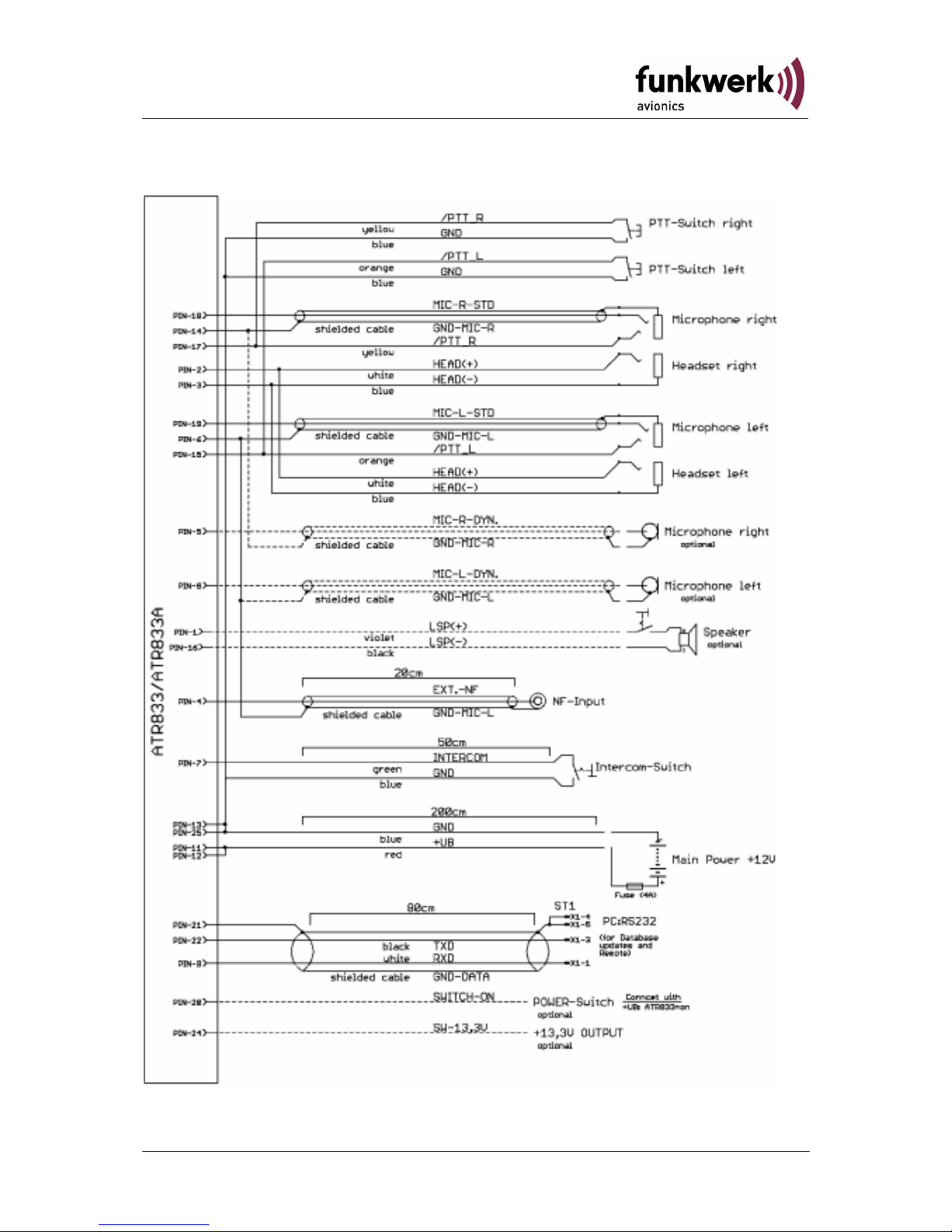
3.7.3 Wiring Diagram
PIN 24: I = 200 mA (internal fuse)
32 Dokument-Nr.: 01.1402.010.71e / Revision: 1.01
Page 33
ATR833 / P/N 833-(1xx)-(1xx)
Operation and Installation
3.8 Antenna
3.8.1 Antenna Selection
• A VHF-COM-Antenna with an impedance of 50 Ohm is required.
• Choose an antenna type approved for the aircraft and the mounting
location.
• Specified features depend on proper installation of the antenna.
3.8.2 Installation Recommendation
• Take note of the antenna manufacturer’s instructions.
• The metallic contact between airplane surface and antenna-GND
must be very good. On non-metallic airplanes a metal foil (min. 80 cm
x 80 cm) shall be used as electrical counterweight on the inside of the
belly.
• To avoid a mutual interference of the radios, the antenna isolation
between a voice transmission and a navigation antenna as well as
between double COM antennas should be as large as possible. A
distance of 2 meters usually is sufficient.
• Assemble the antenna in vertical position so on or under the belly that
it is as far distant as possible from all protruding parts (propeller,
chassis, vertical stabilizer)
• For glider installation the internal antenna installed by the
manufacturer should be used.
The HF antenna wire must not be included in any other
cable sets, for example power supply or microphone. It must
also not be placed together with other antenna wires, for
example NAV or Transponder.
33Dokument-Nr.: 01.1402.010.71e / Revision: 1.01
Page 34
ATR833 / P/N 833-(1xx)-(1xx)
Operation and Installation
3.9 Microphone Settings
The settings of MIC and VOX values are essential for Intercom.
(MIC=Microphone level see 2.8.4, VOX=threshold level see 2.4.3).
Using VOX the threshold level is adjusted so that usual flight noise is not
transmitted to the headphones, but only an additional signal caused by
speaking will start intercom operation. With very strong background
noise or uncompensated microphones VOX can be deactivated by
setting VOX=01 (see 2.4.3). In this case intercom is activated using the
intercom switch (not PTT), which connects pin 7 (intercom) of the
equipment connector to GND.
If necessary, e. g. in a tandem cockpit, use two parallel connected PTT
buttons.
For operation in VOX mode pin 7 has to be connected to GND
permanently.
Transmission merely operates when PTT is pressed.
The suppression of background noise is only possible using differential
microphones, as they are usual with modern headsets. Normal electret
microphones are not suitable.
3.10 Post-Installation Check
A
certified maintenance shop must verify proper operation of
the VHF Transceiver System.
When installation is completed all steering and control functions of the
aircraft are to be examined, in order to exclude disturbances by the
wiring.
The SWR shall not exceed 3:1.
Furthermore a test flight is recommended, in order to guarantee the
proper in-flight operation of the radio:
• In a flight altitude of at least 2000 ft contact a ground station in a
distance of at least 50 km (30 nautical miles).
• Pay attention to unusual electrical interference.
• If possible, perform the radio test on frequencies within the upper
and lower VHF communication frequency range
34 Dokument-Nr.: 01.1402.010.71e / Revision: 1.01
Page 35
ATR833 / P/N 833-(1xx)-(1xx)
Operation and Installation
3.11 Starting up
Turn the device on with
After start-up the following screen appears:
The Start Screen indicates device type and software version as well as
the date of the frequency database.
After that screen the device changes into normal operation (direct input
mode).
3.12 Accessories
Suitable accessories like antennas, cable sets, connectors or switches
can be purchased at our online shop on
www.funkwerk-avionics.com.
35Dokument-Nr.: 01.1402.010.71e / Revision: 1.01
Page 36
ATR833 / P/N 833-(1xx)-(1xx)
Operation and Installation
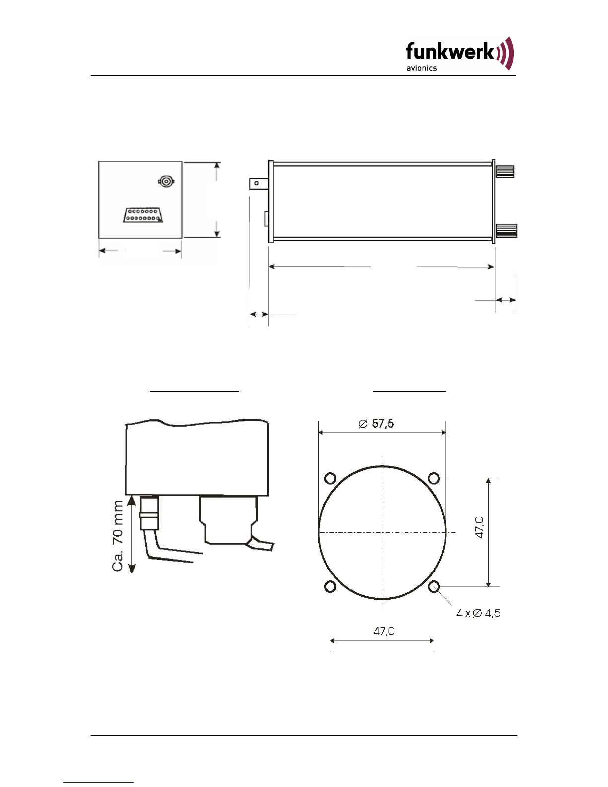
3.13 Drawings
3.13.1 Dimensions
20 mm
18 mm
168 mm
61 mm
65 mm
3.13.2 Mounting Advices
Connection Area
Panel Cut-out
For mounting in panels with a thickness of 3 mm to 5 mm longer screws
are required. Order no.: ZUB1.
36 Dokument-Nr.: 01.1402.010.71e / Revision: 1.01
Page 37

ATR833 / P/N 833-(1xx)-(1xx)
Operation and Installation
4 APPENDIX
4.1 Frequency/Channel-Plan
In the following table examples for operating and displayed frequencies
in the range between 118.000 ... 118.100 MHz are given. This table can
be continued to 136.975 MHz following the same scheme.
Operating
frequency
(MHz)
Channel
Spacing
(kHz)
Displayed
Channel
8.33/25 kHz Mode
Displayed Channel
25 kHz Mode
118.0000 25 118.000 118.000
118.0000 8.33 118.005
118.0083 8.33 118.010
118.0166 8.33 118.015
118.0250 25 118.025 118.020
118.0250 8.33 118.030
118.0333 8.33 118.035
118.0416 8.33 118.040
118.0500 25 118.050 118.050
118.0500 8.33 118.055
118.0583 8.33 118.060
118.0666 8.33 118.065
118.0750 25 118.075 118.070
118.0750 8.33 118.080
118.0833 8.33 118.085
118.0916 8.33 118.090
118.1000 25 118.100 118.100
118.1000 8.33 118.105
etc. etc. etc. etc.
37Dokument-Nr.: 01.1402.010.71e / Revision: 1.01
Page 38

ATR833 / P/N 833-(1xx)-(1xx)
Operation and Installation
4.2 Technical Data
GENERAL
COMPLIANCE ETSO-2C37e,ED-23B Class 4
ETSO-2C38e,ED-23B Class C
TSO-C37d, RTCA DO-186A Class 6
TSO-C38d, RTCA DO-186A Class E
DIMENSIONS
Height: 65 mm (2,56 in)
Width: 65 mm (2,56 in)
Length: 248 mm (9,76 in) behind the panel
WEIGHT 1,32 lbs (0,6 kg)
MOUNTING Panel Mounted
TEMPERATURE RANGES
OPERATION
STORAGE
-20 °C ... +55 °C,30 min at +70 °C
-55 °C . . +85 °C
MAX. HEIGHT 50000ft
VIBRATION DO-160D, Cat. S, Vibration Curve M
HUMIDITY RTCA DO-160D, Cat. A
SHOCK
6 G operation
20 G crash safety
RTCA DO-160D ENV.CAT. [C1Z]CAA[SM]XXXXXXZBAAA[YY]M[B3F3]XXA
POWER SUPPLY
13,8 VDC (11 VDC ... 18 VDC)
• transmitter: 2,5A
• receiver: 0,2A (Standby),max. 0,5A
• audio power amplifier: up to 1A
emergency ops, restricted function: 11 VDC
POWER CONSUMPTION Standby: 2,8W, transmitting 35W
FUSE external fuse required: 4 A, slow-blow
FREQUENCY RANGE 118,000 MHz .. 136,975 MHz
FREQUENCY STABILITY ±30 ppm at -20 °C .. + 55 °C
COMPASS-SAFE
DISTANCE
30cm
INTERCOM-INPUT
The microphone inputs are connected to the
Intercom input. 100 mVRMS at the microphone
input produce 0,5 W output power at the
Headphone output (300 Ω).
NF (AUDIO) - INPUT 1V/600Ω
38 Dokument-Nr.: 01.1402.010.71e / Revision: 1.01
Page 39

ATR833 / P/N 833-(1xx)-(1xx)
Operation and Installation
TRANSMITTER
POWER OUTPUT
6 W (nominal)
4 W (minimal)
HARMONIC DISTORTION < 10 % bei 70 % modulation
SIDETONE OUTPUT >0,5W into 300Ω (per headphone)
MICROPHONE INPUTS
2 x standard (50mV…2V) into 100Ω
2 x dynamic microphone
HARMONIC CONTENT >60dBc
MODULATIONFIDELITY deviation 6dB (350…2500Hz)
CARRIER NOISE LEVEL >35dB at 70% modulation
UNWANTED FREQUENCY-
MODULATION
<1kHz at m=70% / 1kHz
DUTY CYCLE
2 minutes on, 4 minutes off;
automatic turn-off after 2 minutes of
continuous transmit operation
RECEIVER
SENSITIVITY
-105 dBm (6 dB S+N/N,
m = 30 % /1 kHz)
BANDWIDTH / 25 KHZ -6-dB-bandwidth > ±8.0 kHz
BANDWIDTH / 8.33 KHZ -6-dB- bandwidth > ±2.78 kHz
SELECTIVITY
(channel spacing 25 KHZ)
-40-dB- bandwidth < ±17.0 kHz
-60-dB- bandwidth < ±22.0 kHz
SELECTIVITY
(channel spacing 8.33 KHZ)
-60-dB- bandwidth < ±7.37 kHz
SPEAKER-OUTPUT ≥4 W into 4 Ω (speaker output)
AGC CHARACTERISTICS
AF output deviation < 6 dB
from 10 µV to 10 mV
SQUELCH Automatic Squelch (adjustable)
SPURIOUS RESPONSES > 80 dB
DISTORTION (350…2500Hz)
<25% at rated power (85% / -33dBm)
<10% at 10dB below rated power (70%
/ -33dBm)
39Dokument-Nr.: 01.1402.010.71e / Revision: 1.01
Page 40

ATR833 / P/N 833-(1xx)-(1xx)
Operation and Installation
4.3 Environmental Conditions
Characteristic DO–160D Section Cat Condition
Temperature / Altitude 4.0
Low ground survival
temperature
4.5.1 – 55°C
Low operating temperature 4.5.1 – 20°C
High ground survival
Temperature
4.5.2 + 85°C
High Short-time Operating
Temperature
4.5.2 + 70°C
High Operating Temperature 4.5.3
C1
+ 55°C
In-Flight Loss of Cooling 4.5.4 Z
No auxiliary cooling
required
Altitude 4.6.1 C1 35 000 ft
Temperature Variation 5.0 C
2°C change rate minimum
per minute
Humidity 6.0 A
Shock 7.0 A
6 G operational shocks
20 G Crash Safety
Test Type R in all 6
directions
Vibration 8.0 S Vibration Curve M
Explosion Proofness 9.0 X No test required
Water Proofness 10.0 X No test required
Fluids Susceptibilities 11.0 X No test required
Sand and Dust 12.0 X No test required
Fungus Resistance 13.0 X No test required
Salt Spray 14.0 X No test required
Magnetic Effect 15.0 Z
Less than 0,3 m Compass
Safe Distance
Power Input (DC) 16.0 B
Voltage Spike Conducted 17.0 A
Audio Frequency Conducted
Susceptibility
18.0 A
40 Dokument-Nr.: 01.1402.010.71e / Revision: 1.01
Page 41

ATR833 / P/N 833-(1xx)-(1xx)
Operation and Installation
Characteristic DO–160D Section Cat Condition
Induced Signal Susceptibility 19.0 A
Radio Frequency
Susceptibility
20.0 YY
Emission of RF Energy 21.0 M
Lightning Induced Transient
Susceptibility
22.0
B3
F3
Lightning Direct Effects 23.0 X No test required
Icing 24.0 X No test required
Electrostatic Discharge (ESD) 25.0 A
41Dokument-Nr.: 01.1402.010.71e / Revision: 1.01
 Loading...