

Page 1

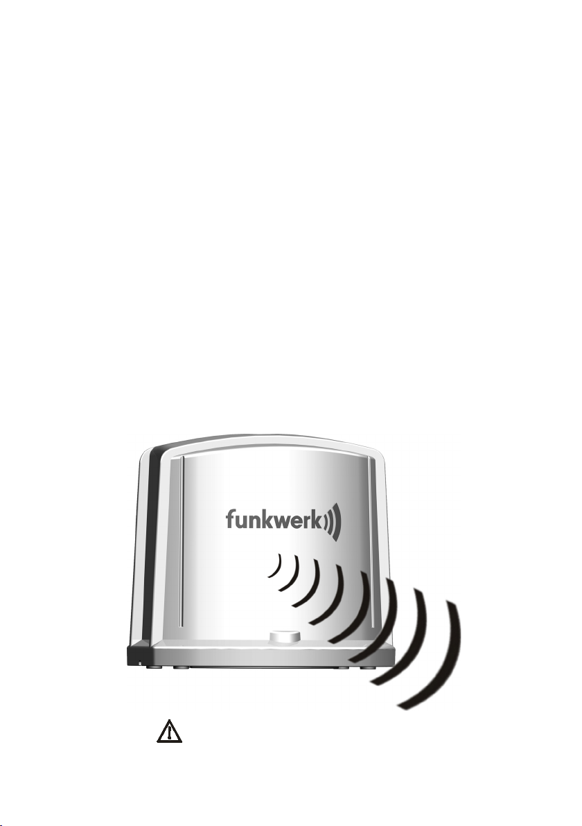
Aktive Antenne
Active antenna
Aktif anten
Antena activa
Ein Unternehmen der Funkwerk AG.
155 8000 0.05
Page 2

2
Lesen Sie die Sicherheitshinweise in diesem Handbuch auf Seite 6!
Read the Safety Information section of this user guide on page 18!
Oku sayfa 30 bu kullanıcı kılavuzunun Güvenlik bilgileri bölümünde!
¡Lea las indicaciones de seguridad en la página 44 de este manual!
Funkwerk Dabendorf GmbH
Märkische Straße
D-15806 Dabendorf
Telefon +49 (0) 3377316-0
Telefax +49 (0) 3377316-300
eMail info @ fwd-online.de
Internet www.fwd-online.de
Änderungen im Sinne des technischen Fortschrittes und Abweichungen vom Lieferumfang vorbehalten! Alle Rechte vorbehalten! Vervielfältigungen, auch auszugsweise, nur mit schriftlicher Genehmigung!
Page 3

3
Inhaltsverzeichnis
Einführung ................................................................8
Konformitätserklärung.............................................8
Sicherheitshinweise .................................................8
Entsorgungshinweis...........................................................9
Funktionsbeschreibung ............................................10
Lieferumfang ............................................................11
Montage und Inbetriebnahme ...................................12
Voraussetzungen feststellen .............................................12
Funktionstest .....................................................................12
Innerhalb der Wohnung (Beispiel ohne Wanddurchführung) ...... 14
Befestigung an der Außenwand .........................................15
Befestigung am Antennenmast .........................................16
Problembehebung ....................................................16
Deutsch English Türk Español
Technische Daten ......................................................17
Übertragungsgeschwindigkeit ..................................18
Hotline .....................................................................19
Page 4

4
Table of contents
Deutsch English Türk Español
Introduction ..............................................................20
Declaration of Conformity ........................................20
Safety Instructions ...................................................20
Instructions for Disposal ...................................................21
Function Description .................................................22
Scope of Supply ........................................................23
Mounting and getting started....................................24
Finding out preconditions ..................................................24
Function Test ......................................................................24
Within the house (example without wall duct) ................................ 26
Mounting to the Wall ..........................................................27
Mounting to the Antenna Mast ...........................................28
Trouble Shooting .......................................................28
Technical Specifications ............................................29
Transmission speed ..................................................30
Hotline .....................................................................31
Page 5

5
İçindekiler
Giriş ..... ....................................................................32
Uygunluk beyanı .......................................................32
Güvenlik açıklamaları ...............................................32
Cihazın imha edilmesi ........................................................33
Fonksiyon tanımı ......................................................34
Teslimat paketi içeriği ..............................................35
Kurma ve çalıştırma .................................................36
Önkoşulları belirleme ........................................................36
Fonksiyon testi ...................................................................36
Evin içersinde (duvar bağlantısı olmayan örnek) ............................38
Dış duvara bağlantısı .........................................................39
Anten direğine bağlantısı ...................................................40
Problemin ortadan kaldırılması ...............................40
Deutsch English Türk Español
Teknik özellikler .......................................................41
Yayın hızı ...................................................................42
Danışma hattı ...........................................................43
Page 6

6
Índice
Deutsch English Türk Español
Introducción ..............................................................44
Declaración de conformidad .....................................44
Indicaciones de seguridad ........................................44
Indicaciones de desecho ....................................................45
Descripción de funciones ..........................................46
Contenido ..................................................................47
Montaje y puesta en funcionamiento ........................48
Verificar condiciones ..........................................................48
Test de funcionamiento ......................................................48
Dentro de la vivienda (ejemplo sin pasamuros) ............................ 50
Fijación a la pared exterior ................................................51
Fijación al mástil de antena ...............................................52
Solución de problemas .............................................52
Datos Técnicos ..........................................................53
Velocidad de transferencia .......................................54
Línea de atención telefónica .....................................55
Page 7

7
Deutsch English Türk Español
Page 8
8
Einführung
Vielen Dank, dass Sie sich für die AKTIVE ANTENNE der Funkwerk Dabendorf
GmbH entschieden haben!
Die AKTIVE ANTENNE sorgt bei Ihnen zuhause für eine optimale Sende- und Empfangsleistung und damit für einen verbesserten Betrieb Ihres UMTS- Endgerätes.
Bitte überprüfen Sie zunächst anhand der Angaben im Lieferumfang, ob alle Teile
vollständig vorhanden sind.
Konformitätserklärung
Wir, die Funkwerk Dabendorf GmbH, erklären voll verantwortlich, dass das Produkt AKTIVE ANTENNE den Bestimmungen der Directive 1999/5/EC des Rates der
Europäischen Union entspricht.
0681
Die Konformitätserklärung ist unter
www.fwd-online.de/conformity
Sicherheitshinweise
Die Antenne ist nur für den vom Hersteller angegebenen Zweck zu verwenden.
Vorsicht beim Auspacken: Erstickungsgefahr für Kleinkinder durch verschlucken von Kleinteilen!
Gerät nicht ins Feuer werfen!
Für Personen ist ein Abstand von mindestens 20cm zur Antenne einzuhalten! Besondere Vorsicht ist im Bereich der Antenne geboten für Personen
mit Herzschrittmacher!
einsehbar.
Page 9
9
Das Gerät darf nur von autorisiertem Fachpersonal geöffnet und gewartet
werden!
Es ist nur zugelassenes Zubehör zu verwenden!
Vor Inbetriebnahme der Antenne in/an Gebäuden informieren Sie sich bitte über
die einzuhaltenden Mindestabstände zu empfindlichen Geräten (z.B. in Krankenhäusern, an Tankstellen, an Orten die besonders als gefährdet gekennzeichnet sind, wie explosive Stoffe, brennbare Flüssigkeiten und Gasen, etc.)!
Bitte verlassen Sie sich nicht darauf zu jeder Zeit mit diesem Gerät einen
Notruf absetzen zu können!
Nutzen Sie ausschließlich die im Lieferumfang befindlichen Komponenten.
Die fest verbundene Koaxialleitung darf im verlegten Zustand nicht auf Zug
beansprucht werden. Führen Sie das Kabel so, dass es nicht scheuert oder
gequetscht werden kann. Der Biegeradius von 20mm darf nicht unterschritten werden!
Die Koaxialleitung darf weder verlängert, noch gekürzt werden! Produktzulassung erlischt!
Wird das Gerät über einen längeren Zeitraum nicht benutzt (z.B. Urlaub),
sollte das Steckernetzteil vom Netz getrennt werden!
Im Falle der Außenmontage der Antenne sollte ein Fachmann mit Kenntnis
der gültigen Fachstandards beauftragt werden!
Bei der Montage am Haus oder an einem Antennemast sind geeignete Maßnahmen zum Blitzschutz am Haus zu treffen!
Entsorgungshinweis
Gerät nicht im Hausmüll entsorgen!
Elektronische Geräte sind entsprechend der Richtlinie über Elektro- und
Elektronik-Altgeräte über die örtlichen Sammelstellen für Elektronik-Altgeräte zu entsorgen!
WEEE-Reg.-Nr. DE 81447333
Page 10
10
Funktionsbeschreibung
Die Aktive Antenne À ist geeignet für die Frequenzbänder GSM 900, GSM 1800 und
UMTS Band I. Sie unterstützt die Übertragungsverfahren GPRS, HSCSD, EDGE,
UMTS, HSDPA und HSUPA. Der Anschluss an die Endgeräte erfolgt über die im
Lieferumfang befindliche Aufnahme für UMTS-Datensticks.
Das Set der Aktiven Antenne besteht aus dem Grundgerät (Antenne mit integriertem Verstärker), einer 15m langen Koaxialleitung, einem Steckernetzteil und
einer Aufnahme mit integrierter Koppelantenne für UMTS-Datensticks.
Folgende Anschlüsse befinden sich an der Aufnahme:
• Steckverbinder für den Anschluss der Koaxialleitung zur Aktiven
Antenne
• 2,1mmHohlsteckerzumAnschlussderVersorgungsspannung
Die benötigte Versorgungsspannung wird durch das beiliegende externe Steckernetzteil (8 V, 0,9A) bereitgestellt.
Die Aktive Antenne verstärkt das UMTS-Mobilfunksignal zwischen Endgerät und
Außenantenne in Sende- und Empfangsrichtung. Darüber hinaus wird durch die
Richtwirkung der Antenne ein zusätzlicher Gewinn von ca. 7dB erreicht. In den
GSM-Frequenzbändern arbeitet die Antenne passiv, es erfolgt keine Verstärkung.
Senderichtung beachten!
Page 11
11
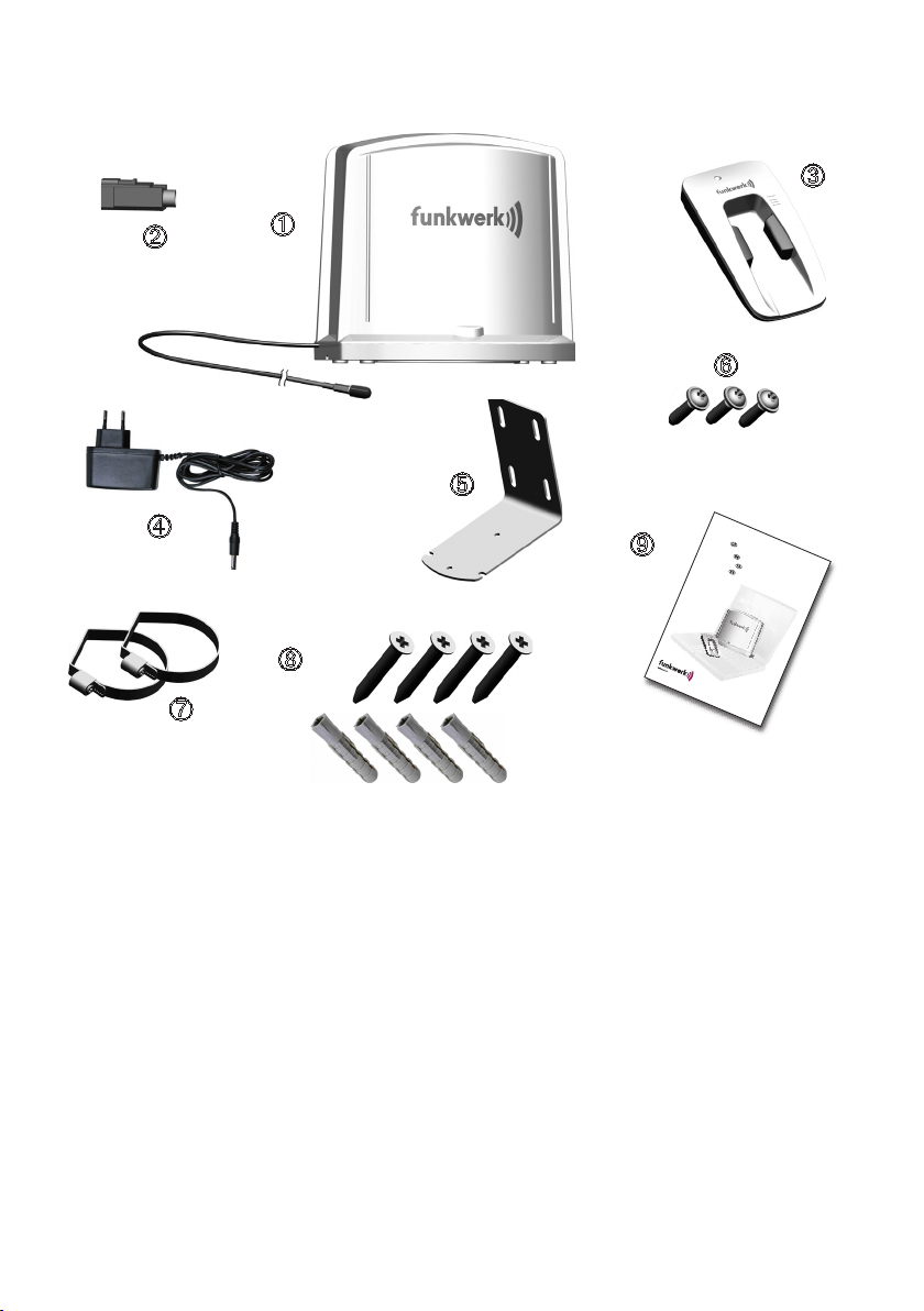
Lieferumfang
Ein Unternehmen der Funkwerk AG.
155 8000 0.04
Aktive Antenne
Active antenna
Aktif anten
Antena activa
À
À - Aktive Antenne mit 15m Koaxialleitung und Schutzkappe
- Kupplergehäuse (FAKRA) für Koaxialleitung
- Aufnahme für UMTS-Datensticks
- Steckernetzteil
- Haltewinkel
- Schrauben zur Befestigung der Antenne (3,5mm x 12mm)
- Schellenbänder
- Schrauben (5x50-St-H) und Dübel (MU 8x50) zur Wandbefestigung
- Bedienungsanleitung
Page 12

12
Montage und Inbetriebnahme
Vor Beginn der Montage
Bitte kontrollieren Sie die Vollständigkeit des Lieferumfangs.
Kontrollieren Sie, ob Ihr UMTS-Datenstick in die Aufnahme passt.
Das beigelegte Kupplergehäuse dient der sicheren Verbindung zwi-
schen Koaxialleitung und der Aufnahme des UMTS-Datensticks.
VORSICHT! DasKupplergehäuse erst auf die Koaxialleitung stecken,
wenn die Verlegung beendet ist! Das gesteckte Kupplergehäuse lässt sich
nicht mehr lösen!
Ist eine Wanddurchführung geplant, lesen und beachten Sie den nachfolgend beschriebenen Ablauf der Montage!
Voraussetzungen feststellen
Um ein stabiles UMTS-Signal zu erhalten, erfragen Sie bei Ihrem Mobilfunkanbieter den Standort des nächstgelegenen Sendemasts in der Umgebung Ihrer Wohnung. Bestimmen Sie dann die Position der Antenne im Außen- oder Innenbereich.
Sie haben drei Varianten zum Verbau der Aktiven Antenne:
Antenne innerhalb der Wohnung
Die Aktive Antenne À wird innerhalb der Wohnung an einem Ort positioniert, an
dem ein stabiles UMTS-Signal verfügbar ist.
Antenne außen am Haus
Die Aktive Antenne À wird mit dem beiliegenden Haltewinkel an der Hauswand befestigt.
Antenne an einem Antennenmast
Die Aktive Antenne À wird mit dem Haltewinkel und den beiliegenden Schellenbändern an einem Antennenmast befestigt.
Funktionstest
1. Standort des Sendemastes zur Antenne feststellen.
2. Antenne ungefähr so ausrichten, sodass das Logo zum Standort des Sende mastes zeigt. Eine Winkelkorrektur von ±30° ist möglich (bei Montage auf Be festigungswinkel).
3. PC bzw. Notebook mit Software des Mobilfunkanbieters in Betrieb nehmen.
4. Datenstick über USB-Kabel (nicht im Lieferumfang) mit PC bzw. Notebook
verbinden.
5. Aufnahme für UMTS-Datenstick mit dem Steckernetzteil verbinden und in
Betrieb nehmen.
Page 13
13
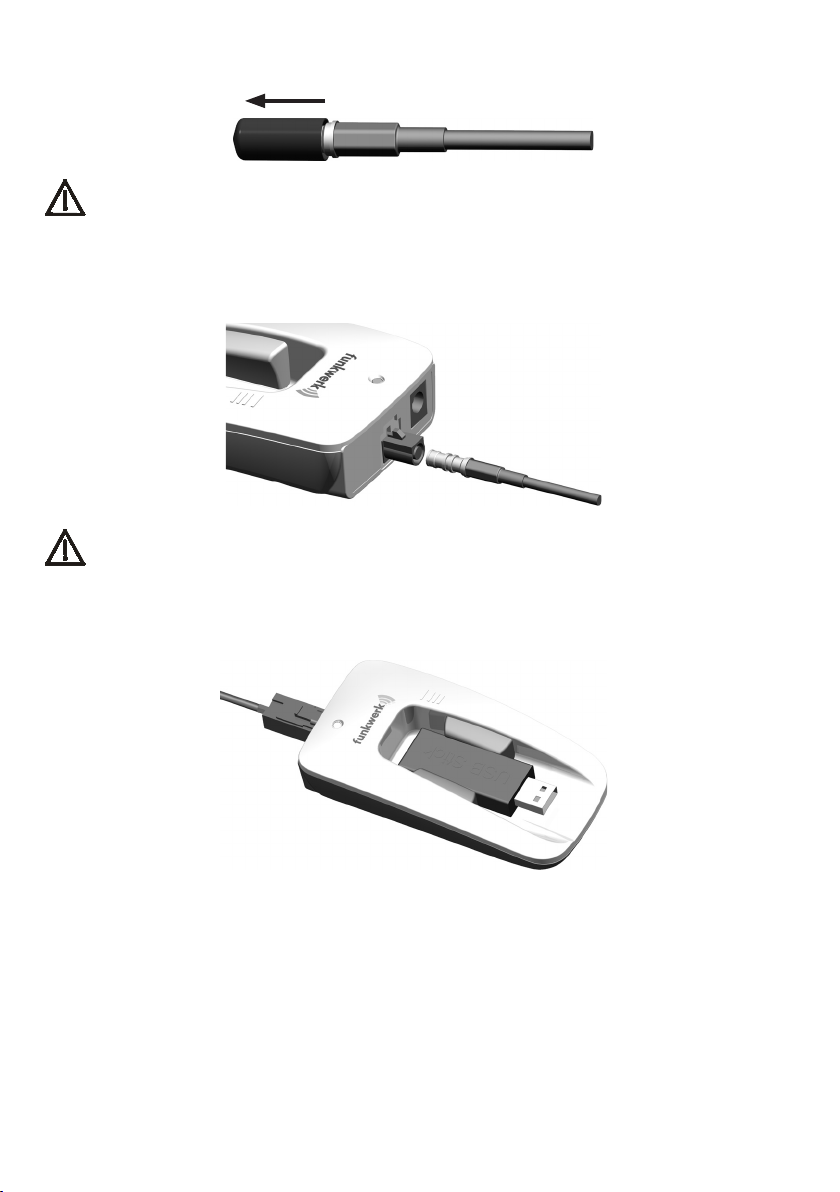
6. Schutzkappe vorsichtig von der Koaxialleitung abziehen.
Hinweis! Die Schutzkappe wird für die Wanddurchführung benötigt.
7. Den nun freiliegenden HF-Kontakt vorsichtig an den mittleren Steckver binder der Datenstickaufnahme anschließen. Die Antenne ist in Betrieb,
wenn die grüne LED der Aufnahme leuchtet.
Achtung! Diese Verbindung hat keinen dauerhaften Halt!
(nur für Testzwecke)
8. UMTS-Datenstick nun in die Aufnahme einlegen und zwischen die Halte bügel klemmen.
9. Sendeleistung anhand der Provider-Software prüfen. Gegebenenfalls Position
der Antenne korrigieren.
10. Position der Antenne festlegen und fixieren.
11. HF-Kontakt der Koaxialleitung wieder vorsichtig von der Aufnahme
abziehen.
Page 14
14
Dauerhafte Montage
Schieben Sie die Schutzkappe über den HF-Kontakt des Steckers zum Schutz
vor Verschmutzungen bei evtl. Wanddurchführungen und Verlegung des Kabels!
Planen Sie nun die Verlegung der Koaxialleitung.
Innerhalb der Wohnung (Beispiel ohne Wanddurchführung)
Verlegen Sie das Kabel zu dem Ort, an dem Sie die Aufnahme für den UMTSDatenstick aufstellen wollen. Beachten Sie dabei, dass ein Biegeradius von 20 mm
nicht unterschritten werden darf.
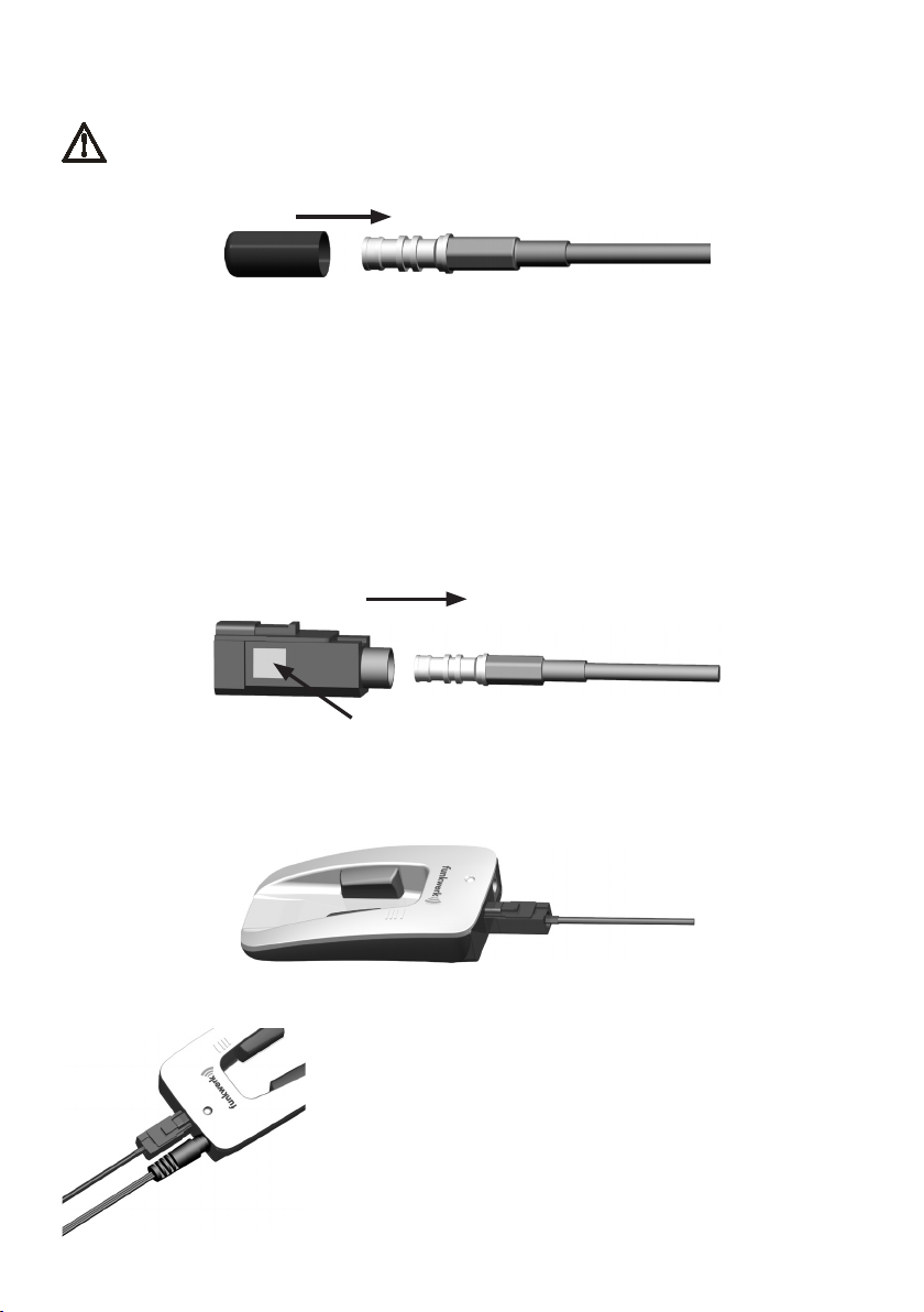
Ziehen Sie die Schutzkappe vorsichtig von der Koaxialleitung.
Schieben Sie das Kupplergehäuse über den HF-Kontakt (A) am Ende der Koaxi-
alleitung und drücken Sie das magentafarbene Rastelement fest (B).
A
B
Verbinden Sie die Koaxialleitung mit dem dafür vorgesehenen Anschluss an der
Aufnahme für den UMTS-Stick. Der Stecker der Koaxialleitung rastet hörbar
ein.
Verbinden Sie das Steckernetzteil nun wieder mit der
Aufnahme .
Die Leuchtdiode an der Aufnahme des UMTS-Sticks
leuchtet, wenn die Antenne mit Strom versorgt ist und
signalisiert Ihnen die Einsatzbereitschaft der Anlage.
Sie können jetzt den UMTS-Stick Ihres Mobilfunkanbieters in die Aufnahme einlegen und über ein USBVerlängerungskabel (nicht im Lieferumfang) an Ihrem
Endgerät (PC, Notebook) betreiben.
Page 15
15
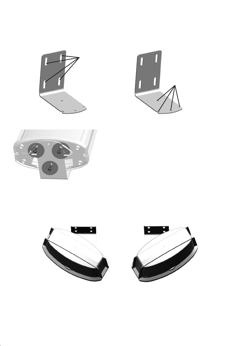
Befestigung an der Außenwand
Bohren Sie ein ausreichend großes Loch durch die Hauswand. Befestigen Sie nun
den Haltewinkel in der Nähe des Durchgangsloches mit den mitgelieferten Befestigungsmaterialien.
Löcher für
Befestigung
an der Wand.
Befestigen Sie dann die Antenne am Haltewinkel.
Löcher für die
Befestigung
der Antenne
Bei der Montage an der Wand besteht die Möglichkeit, die Antenne um jeweils 30
Grad nach links bzw. rechts zu verstellen. Nutzen Sie diese Verstellmöglichkeit,
um Ihre Antenne optimal auf den Sendemast auszurichten.
Gehen Sie nun weiter vor, wie im Abschnitt „Innerhalb der Wohnung“ (S.14) beschrieben.
Page 16
16
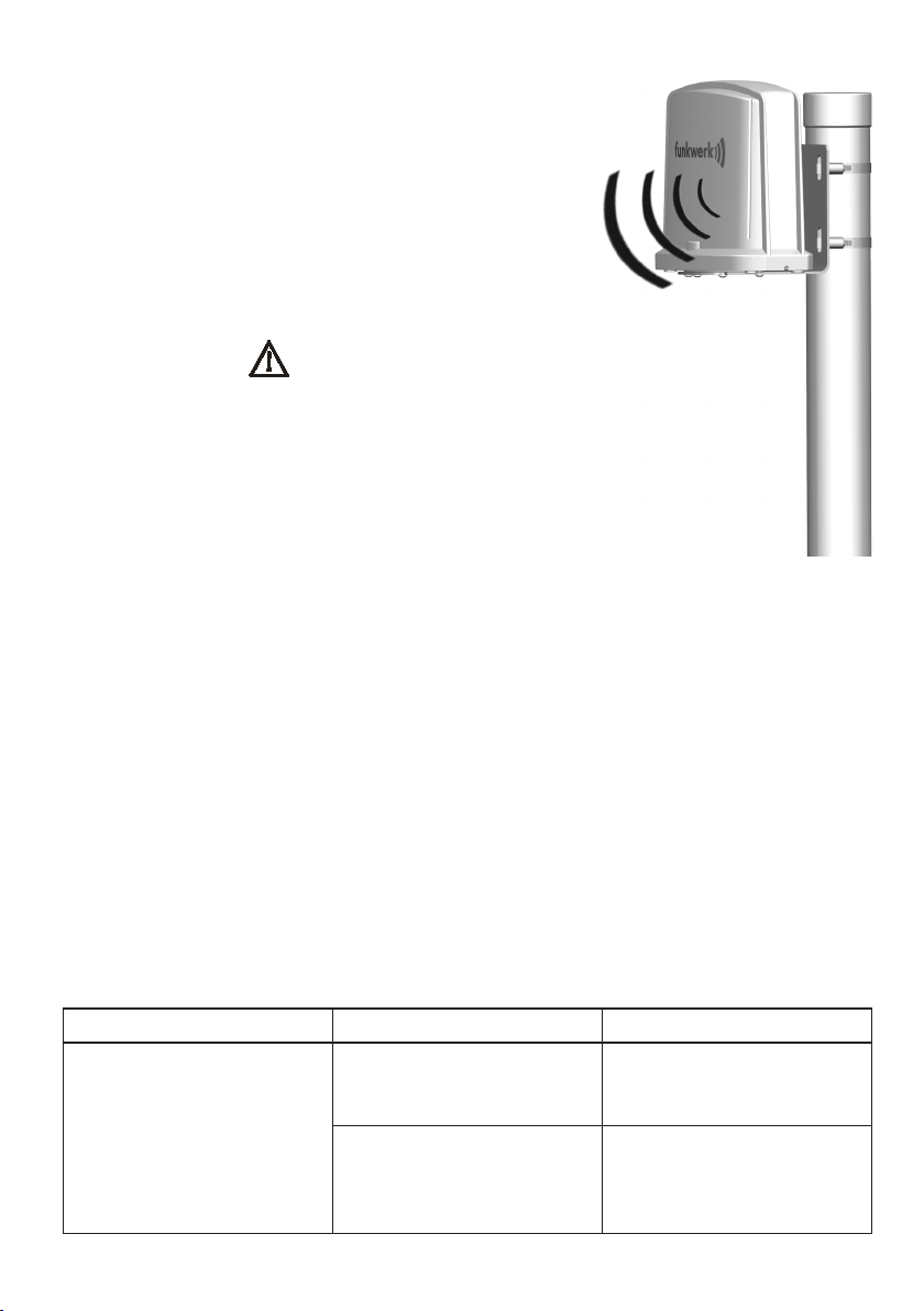
Befestigung am Antennenmast
Befestigen Sie den mitgelieferten Haltewinkel am
Boden der Antenne mit den mitgelieferten Schrauben.
Führen Sie jetzt die im Lieferumfang enthaltenen
Schellenbänder durch die Langlöcher des Haltewinkels. Befestigen Sie den Haltewinkel (incl.
Antenne) mit den Schellenbändern am Mast und
richten Sie diesen auf den Sendemast aus.
Senderichtung beachten!
Gehen Sie nun weiter vor, wie im Abschnitt „Innerhalb der Wohnung“ (S.14) beschrieben.
Problembehebung
Problem mögliche Ursache Abhilfe
Schlechter Empfang
trotz verfügbarer
UMTS-Verbindung.
Das Gerät ist nicht
eingeschaltet (Status-LED aus).
Die Kopplung der Antenne zwischen UMTSDatenstick und Aufnahme ist unzureichend.
alle Steckverbindungen
prüfen / Steckernetzteil
in Steckdose stecken
Drehung des UMTSDatensticks um 180 Grad
um seine Längsachse.
Page 17

17
Technische Daten
Geeignet für : UMTS und GSM900/GSM1800
Unterstützte Übertragungsverfahren : UMTS, HSDPA, HSUPA, GPRS, EDGE,
HSCSD
Betriebsspannung : 230 V über Netzteil
Maximale Sendeleistung ERP*) : UMTS Band 1
ca. 30 dBm (1W) in Hauptstrahlrichtung
: GSM 900/1800
passiv (ohne Verstärkung), rundstrahlend
Verstärkung bei UMTS-Band 1 : die Verstärkung ist so eingestellt, dass die
Koppelverluste der Aufnahme für den
UMTS-Datenstick und die Verluste des fest
verbundenen Verbindungskabels exakt
ausgeglichen werden
System-Verstärkung : in Hauptstrahlrichtung ca. 7dB im
UMTS-Band 1
Öffnungswinkel der Antenne: 60 °
Stromversorgung : über Steckernetzteil an 230 V~
max. Leistungsaufnahme: ca. 6W
im Standby: ca. 2W
Leerlauf: max 0,3W
Steckernetzteil : 8 V / 0,9 A
Betriebstemperatur : -20°C … 70°C
HF-Steckverbindung : FAKRA
Steckverbindung Stromversorgung an
der Aufnahme des UMTS-Datensticks : Hohllochstecker 2,1
Kabellänge, -typ : 15 m, Leoni Dacar 031
Gehäuse : Kunststoff ASA
*) ERP = effektive abgestrahlte HF-Leistung
Page 18

18
Übertragungsgeschwindigkeit
Maximale, in der Praxis genutzte Übertragungsraten:
GPRS: 56 Kbit/s
EDGE: 220 kbit/s
UMTS: 384 Kbit/s
HSUPA: bis 2.000 Kbit/s (typisch: 1.450 Kbit/s)
HSDPA. bis 28.800 Kbit/s (typisch: 3.600 bzw. 7.200 Kbit/s)
Page 19

19
Hotline
Haben Sie Fragen oder Anregungen? Möchten Sie sich näher informieren? Benötigen Sie Beratung und Service vor Ort? Rufen Sie uns an!
In den folgenden Zeiten steht Ihnen unsere Hotline zur Verfügung:
Montag – Donnerstag von 7.15 Uhr bis 18.00 Uhr
Freitag von 7.15 Uhr bis 16.00 Uhr
Folgende Schritte sollten Sie einhalten:
→ Prüfen Sie, ob Sie das Problem mit Hilfe des vorstehenden Abschnittes
„Problembehebung“ lösen können.
→ Versuchen Sie, das Problem möglichst genau zu beschreiben.
Unsere Hotline können Sie unter folgenden Nummern erreichen:
innerhalb Deutschlands (kostenlos): Telefon: 0800 - 0 393 393
außerhalb Deutschlands: Telefon: +49 (0) 3377 - 316 233
+49 (0) 3377 - 316 234
Telefax: +49 (0) 3377 - 316 244
Page 20

20
Introduction
Thank you very much for opting in favour of the ACTIVE ANTENNA of Funkwerk
Dabendorf GmbH!
The ACTIVE ANTENNA takes care of the very best transmission and reception
power and thus ensures improved operation of your UMTS terminal device.
First of all, and based on the data concerning the scope of supplies please check
whether all parts are available.
Declaration of Conformity
We, Funkwerk Dabendorf GmbH, declare that we bear the entire responsibility for
the product ACTIVE ANTENNA fully complying with the provisions of the European
Council Directive 1999/5/EC.
0681
The Declaration of Conformity is open to inspection under
formity
.
Safety Instructions
The antenna is only to be used for the purpose indicated by the manufacturer.
Caution when unpacking:
Danger of suffocation for infants when small pieces are swallowed!!
Do not dispose of in a fire!
Persons must observe a distance of at least 20cm to the antenna! Special
caution is required for persons wearing a pacemaker!
www.fwd-online.de/con-
Page 21

21
The device may only be opened and serviced by specialist personnel!
Only use approved accessories!
Before using the antenna in/on buildings, please make sure you are informed
of the minimum distances required to sensitive devices (e.g. in hospitals, at gas
stations, at places labelled as especially endangered, including explosive materials, combustible fluids and gases etc.)
Do not rely on this device for emergency communication!
Use exclusively the components included in the scope of delivery. The fixedconnected coaxial cable must not be subjected to tension in the laid status.
Route the cable so that it cannot rub against other objects or be crushed. The
bending radius of 20 mm must not be fallen below!
The coaxial line may not be extended or shortened! Product Approval expires!
If the device is not used for a longer period of time (e.g. vacation), the wall
power supply should be pulled out of the power socket!
A specialist with know-how about the applicable professional standards
should be commissioned with mounting the antenna outdoors!
With the installation on a house or on an antenna mast, suitable measures
are to be taken for lightning protection on the house!
Instructions for Disposal
Do not dispose of the device in domestic waste!
Electronic devices are to be disposed of in compliance with the directive
governing old electric and electronic devices via the local collection sites
for electronic waste!
WEEE-Reg.-No. DE 81447333
Page 22

22
Function Description
The Active Antenna À is suitable for the frequency band range GSM 900, GSM 1800
and UMTS Band I. It supports the transmission process GPRS, HSCSD, EDGE,
UMTS, HSDPA and HSUPA. The connection to the terminal devices is effected using
the mounting UMTS data stick included in the supplies.
The set of an active antenna consists of a basic device [antenna with integrated amplifier], a 15 m long coaxial line, a wall power supply unit and a mounting with
integrated connecting antenna for UMTS data sticks.
The following connections are found on the mounting:
• Plug connector for the connection of the coaxial line to the active
antenna
• 2,1mmbarrelconnectorforsupplyvoltage
The supply voltage required is provided by the enclosed external power supply unit
(8 V, 0,9A).
The active antenna amplifies the UMTS mobile radio signal between the terminal
device and the outdoor antenna in transmission and receiving direction. Furthermore, an additional yield of approx. 7dB is achieved through the directive array. In
the GSM frequency bands the antenna is passive, no boosting is effected.
Note transmission direction!
Page 23

23
Scope of Supply
Ein Unternehmen der Funkwerk AG.
155 8000 0.04
Aktive Antenne
Active antenna
Aktif anten
Antena activa
À
À - active antenna with 15 m coaxial line and protection hood
- coupler casing (FAKRA) for coaxial line
- mounting for UMTS data stick
- power supply unit
- mounting bracket
- screw to mount the antenna (3,5mm x 12mm)
- loop clamps
- screws [5x50 STH] and dowels [MU 8x50] for wall mounting
- Operating Manual
Page 24

24
Mounting and getting started
Before installation
Please check the supplies for completeness.
Test whether your UMTS data stick fits into the mounting .
The coupler casing included in the supplies is for the safe connection
between coaxial line and the mounting of the UMTS data stick.
ATTENTION! Do not stick the coupler casing onto the coaxial line before
laying work is completed! The coupler casing cannot be removed after
connection!
If the penetration through the wall is planned with, or must have, a small
diameter, please read and observe the mounting steps described in the
following!
Finding out preconditions
To ensure you to get a sound UMTS signal please ask your mobile radio provider
where the nearest transmitter mast is located in the surroundings of your home.
Now lay down the position of the antenna in the outdoor or indoor area.
You have three different installation variants for your active antenna:
Antenna within the house
The active antenna À is positioned within the house at a place at which a sound
UMTS signal is available.
Antenna outside on the house
The active antenna À is mounted to the house wall with the enclosed mounting
bracket .
Antenna on an antenna mast
The active antenna À is mounted to the antenna mast with the enclosed mounting bracket and the loop clamps .
Function Test
1. Find out where the transmitter mast is located in relation to the antenna.
2. Align the antenna approximately; the logo should point to the location of the
transmitter mast. An angular deviation of 30° is possible [when mounting to a
mounting bracket].
3. Now use the software of the mobile ‚phone provider to start up PC or notebook.
4. Connect data stick via USB cable [not included in supplies] with PC or notebook.
5. Connect mounting for UMTS data stick with the power supply unit and
start up.
Page 25

25
6. Draw the protection cap carefully from the coaxial line.
Note! The protection cap is needed for the wall duct.
7. Connect the HF contact that is now exposed carefully with the middle
connector of the data stick mounting The antenna is in operation when the
green LED of the data stick mounting lights up.
Attention! This connection is not permanent! [only for testing]
8. Now insert the data stick into the mounting , clamp between the mounting
brackets respectively.
9. Check transmitter performance with the provider software. Change the
position of the antenna if necessary.
10. Establish and fix the position of the antenna.
11. Draw the HF contact off the coaxial line carefully from mounting
subtract.
Page 26

26
Permanent Mounting
Slip the protection cap over the HF contact of the connector as protection
against soilage for possible wall ducts and when laying the cable!
Now plan the laying of the coaxial cable.
Within the house (example without wall duct)
Lay the cable to the place where you want to set up the mounting for the UMTS
data stick. Note that a bend radius of 20 mm may not be undercut.
Strip the protection cap carefully from the coaxial line.
Pus the coupler casing over the HF contact [A] at the end of the coaxial line and
press the magenta catch element tight [B].
A
B
Connect the coaxial line with the connection provided for the UMTS stick on the
mounting . The connector of the coaxial line catches audibly.
Connect the power supply unit with the mounting
again.
The LED on the mounting of the UMTS stick lights up
when power is supplied to the antenna and shows you
that the device is ready for operation.
You can now insert the UMTS stick of your mobile radio
provider into the mounting and operate it via a USB
extension cable [not included in the supplies] to your
terminal device [PC, notebook].
Page 27

27
Mounting to the Wall
Drill a sufficiently large hole through the house wall. Now mount the mounting bracket near the wall duct with the mounting material found in the supplies.
Holes for
mounting to
the wall.
Then mount the antenna to the mounting bracket.
Holes for
mounting to
the antenna.
When mounting to the wall it is possible to adjust the antenna by 30 degrees each
to the left or to the right. Avail yourself of this adjustment possibility to align your
antenna optimally to the transmitter mast.
Now continue as described in the section „Within the house [p. 26].
Page 28

28
Mounting to the Antenna Mast
Install the mounting brackets supplied to the bottom of the antenna with the screws supplied.
Now insert the loop clamps through the lateral
holes of the mounting bracket. Tighten the mounting
bracket [incl. antenna] with the loop clamps to
the mast and align it to the transmitter mast.
Note transmission direction!
Now continue as described in the Section „Within the House“ [p. 26].
Trouble Shooting
Problem Possible cause Remedy
Poor reception despite UMTS connection being available
The device is not
switched ON [status LED OFF]
The coupling of the antenna between the UMTS
data stick and the mounting is insufficient
Check all connectors / push plugs into
the power socket
Turn the UMTS data
stick by 180 degrees
around its lateral axis.
Page 29

29
Technical Specifications
Suitable for : UMTS and GSM900/GSM1800
Supported transmission process : UMTS, HSDPA, HSUPA, GPRS, EDGE,
HSCSD
Operating voltage : 230 V from power supply unit
Maximum transmission power ERP*) : UMTS band 1
approx. 30 dBm [1W] in main radiation
direction
: GSM 900/1800
passive [without amplification] omni directional
Amplification for UMTS band 1 : the amplification is set to precisely balance
the coupling losses of the UMTS data stick
mounting and the losses of the fix connected cable
System amplification : in the main radiation direction approx. 7dB
in the UMTS band 1
Opening angel of the antenna: 60°
Power supply : via wall power supply unit to 230 V~
max. power input: approx. 6W
in standby: approx. 2W
idle: max 0,3W
Wall power supply unit : 8 V / 0,9 A
Operating temperature : -20°C … 70°C
HF Connector : FAKRA
Connector power supply to the
mounting of the UMTS data stick : Hollow plug 2,1
Cable length, type : 15 m, Leoni Dacar 031
Casing : Plastic ASA
*) ERP = effective radiated power
Page 30

30
Transmission speed
Maximum transmission rates used in practice:
GPRS: 56 kbit/s
EDGE: 220 kbit/s
UMTS: 384 kbit/s
HSUPA: up to 2,000 kbit/s [typical: 1,450 kbit/s]
HSDPA: up to 28,000 kbit/s [typical: 3,600, or 7,200 kbit/s]
Page 31

31
Hotline
Do you have questions or suggestions to make? Are you interested in more detailed
information? Do you need advice or service locally? Simply call us!
Our hotline is at your disposal in the following times
Monday – Thursday from 7:15 hrs to 18:00 hrs
Friday from 7:15 hrs to 16:00 hrs
You should comply with the following steps:
→ Check whether you can solve your problem with the help of the section
„Trouble Shooting“.
→ Try to describe the problem as precisely as possible.
You can contact our hotline under the following numbers:
within Germany, [free of charge]: Telephone: 0800 – 0393 393
outside Germany: Telephone: +49 [0] 3377 – 316 233
+49 [0] 3377 – 316 234
Facsimile: +49 [0] 3377 – 316 244
Page 32

32
Giriş
Funkwerk Dabendorf GmbH kuruluşundan AKTİF ANTEN almaya karar verdiğiniz
için çok teşekkürler!
AKTİF ANTEN evinizde mükemmel bir gönderme ve alma modülüne sahip olup
UMTS-Terminal cihazınızın daha iyi işlemesini sağlar.
Lütfen önce teslimat paketi içeriğindeki tüm parçaların tam olup olmadığını kontrol
ediniz.
Uygunluk beyanı
Funkwerk Dabendorf GmbH olarak AKTİF ANTEN ürününün Avrupa Birliğinin
1999/5/EC sayılı yönetmeliklerine uygun olduğunu tam sorumlulukla beyan ederiz.
0681
Uygunluk beyanını
www.fwd-online.de/conformity
Güvenlik açıklamaları
Anteni sadece üretici firma tarafından belirtilen amaçlar doğrultusunda
kullanınız.
Dikkatli olun açma:
Danger Boğulma bebekler küçük parçalar yutulur için!!
Cihaz ateşe atılmamalıdır!
Kişiler anten için en az 20 cm mesafede uymak gerekir! Özel dikkat kişi kalp
pili takma için gereklidir!
adresinde inceleyebilirsiniz.
Page 33

33
Cihazın açılması ve bakım işlemi sadece yetkili uzman eleman tarafından
yapılmalıdır!
Sadece onaylı aksesuarlar kullanın!
Anteni binanın içine/binaya montajını yapmadan önce lütfen hassas cihazlara karşı (örn. hastanelerde, benzin istasyonlarında, patlayıcı maddeler, yanıcı
sıvılar ve gazlar, vs. gibi özellikle tehlikeli olarak belirtilmiş olunan yerlerde)
dikkat edilmesi gereken asgari mesafeler hakkında bilgi edininiz!
Lütfen bu cihazla herhangi bir zamanda acil olabilir satmak için güvenmeyin!
Sadece teslimat paketi içeriğindeki bileşenleri kullanınız. Sağlam koruma
altındaki koaksiyel kablo döşendiğinde çekmelere maruz kalmamalıdır. Kabloyu sürtülmeyecek veya ezilmeyecek şekilde döşeyin. 20mm’lik kıvrılma
yarıçapının altında kalınmamalıdır!
Koaksiyel hat uzatılamaz veya kısaltılmış! Ürün Onayı sona eriyor!
Cihaz uzun bir zaman dilimi için kullanılmayacaksa (örn. tatile gidildiğinde)
adaptörü elektrik prizinden çıkartın!
Antenin dışarıya montajı gerekli olduğunda geçerli mesleki standartlara
sahip uzman bir elemanın görevlendirilmesi gerekir!
Eve veya bir anten direğine monte edildiğinde evde yıldırıma karşı korunma
konusunda gerekli tedbirler alınmalıdır!
Cihazın imha edilmesi
Cihazı ev çöpü olarak atmayınız!
Elektronik cihazları elektrikli ve elektronik eski cihazlar yönetmeliğine
göre eski elektronik cihazları toplayan yerel toplama yerlerine vererek
imha ediniz!
WEEE-Kayıt No DE 81447333
Page 34

34
Fonksiyon tanımı
Aktif anten À frekans bantları GSM 900, GSM 1800 ve UMTS Bant I için uygundur.
Bu anten GPRS, HSCSD, EDGE, UMTS, HSDPA ve HSUPA yayın yöntemini destekler.
Terminal cihaza bağlantı teslimat paketi içeriğinde bulunan UMTS-Veri kartı için
olan kaydedici üzerinden yapılır.
Aktif anten seti ana cihazdan (amplifikatör entegre edilmiş anten), 15m uzunluğunda
bir koaksiyel kablodan, bir adaptörden ve UMTS-Veri kartı için bağlaştırıcı anten
entegre edilmiş bir kaydediciden oluşur.
Kaydedicide aşağıdaki bağlantılar bulunur:
• AktifantenekoaksiyelkablobağlantısıiçinFAKRA-Konektörü
• Beslemegerilimibağlantısıiçin2,1mmDC-konektörü
İhtiyaç duyulan besleme gerilimi ekte bulunan harici adaptör ile (8 V, 0,9A)
sağlanır.
Aktif anten, terminal cihaz ve dış anten arasındaki UMTS-Mobil radyo sinyalini gönderici ve alıcı yönünde güçlendirir. Bunun yanında ayrıca anten yönlülüğü sayesinde
yakl. 7dB kapsamında ek bir kazanç sağlanılır. GSM-Frekans bantlarında antenler
pasif çalışır, güç yoktur.
Yayın yönüne dikkat edin!
Page 35

35
Teslimat paketi içeriği
Ein Unternehmen der Funkwerk AG.
155 8000 0.04
Aktive Antenne
Active antenna
Aktif anten
Antena activa
À
À - 15m koaksiyel kablolu ve koruma kapaklı aktif anten
- Koaksiyel kablo için kavrama muhafazası (FAKRA)
- UMTS-Veri kartı için kaydedici
- Adaptör
- Tutma dirseği
- Anten bağlantısı için vidalar (3,5mm x 12mm)
- Bağlama kelepçeleri
- Duvara bağlantısı için vidalar (5x50-St-H) ve dübeller (MU 8x50)
- İşletme talimatı
Page 36

36
Kurma ve çalıştırma
Kurmaya başlamadan önce
Lütfen teslimat paketi içeriğinin tam olup olmadığını kontrol edin.
UMTS-Veri kartınızın kaydediciye uyup uymadığını kontrol ediniz.
Ekte bulunan FAKRA-Kavrama muhafazası , koaksiyel kablo ve UMTSVeri kablosu kaydedicisi arasındaki bağlantının güvenli olmasını sağlar.
DİKKAT! Kavrama muhafazasını ancak döşeme işlemi sona erdikten
sonra koaksiyel kabloya takın! Takılmış olunan kavrama muhafazası artık
sökülmez!
Bir duvar bağlantısı planlandıysa aşağıda belirtilen açıklamaları okuyun
ve buna göre hareket edin!
Önkoşulları belirleme
Sabit bir UMTS-Sinyali alabilmek için mobil iletişim sunan kurumunuzdan evinize
en yakın çevredeki anten direği hakkında bilgi edininiz. Sonra dış ya da iç bölümdeki
antenin pozisyonunu belirleyiniz.
Aktif anteni yapılandırma konusunda üç farklı seçeneğiniz var:
Evin içersine kurma
Aktif anteni À evin iç kısmında UMTS-Sinyalinin olduğu bir yere kurabilirsiniz.
Evin dışına kurma
Aktif anteni À ekte bulunan tutma dirseğiyle evin duvarına monte edebilirsiniz.
Bir anten direğine kurma
Aktif anteni À tutma dirseğiyle ve ekte bulunan bağlama kelepçeleriyle bir
anten direğine monte edebilirsiniz.
Fonksiyon testi
1. Anten için anten direğinin yerini belirleyin.
2. Anteni logonun anten direği yerini gösterecek biçimde ayarlayın. ±30° değeri
arasında bir açı sapması mümkün olabilir (montajda bağlantı açısı).
3. PC veya dizüstü bilgisayarınızı mobil iletişim sunan kurumunuzun yazılımıyla
çalıştırın.
4. Veri kartını USB-Kablosuyla (teslimat paketi içeriğinde yok) PC veya dizüstü
bilgisayarınıza bağlantısını yapın.
5. UMTS-Veri kartı için olan kaydedicinin adaptörle bağlantısını yapın ve
çalıştırın.
Page 37

37
6. Koruma kapağını dikkatli şekilde koaksiyel kablodan çıkarın.
Not! Koruma kapağı duvar bağlantısı için gereklidir.
7. Şimdi serbest kalan HF-Kontağını dikkatlice veri kartı kaydedicisinin orta
konektörüne bağlantısını yapın. Kaydedicideki yeşil LED ışığı yandığında
anten çalışır pozisyonundadır.
Dikkat! Bu bağlantı bir süreklilik içermez! (sadece test amaçlı olarak)
8. UMTS-Veri kartını şimdi kaydediciye (3) yerleştirin ve emniyet klipleri
arasında sıkıştırın.
9. Yayın gücünü Provider-Software ile kontrol edin. Gerekli olursa anten
pozisyonunu değiştirin.
10. Anten pozisyonunu tespit ederek sabitleyin.
11. Koaksiyel kablonun yüksek frekans kontağını tekrar dikkatli şekilde
kaydediciden çıkarın.
Page 38

38
Daimi kurulum
Olası duvar bağlantılarında ve kablo döşenirken meydana gelebilecek kirlenmelere karşı korumak için FAKRA-Konektörünün yüksek frekans kontağı
üzerine koruma kapağını geçirin!
Şimdi artık koaksiyel kablonun döşenmesini planlayabilirsiniz.
Evin içersinde (duvar bağlantısı olmayan örnek)
Kabloyu UMTS-Veri kartı kaydedicisini kurmak istediğiniz yere döşeyiniz. Kabloyu döşerken 20 mm’lik kıvrılma yarıçapının altında olmamasına dikkat edin.
Koruma kapağını koaksiyel kablodan çıkarırken dikkat edin.
FAKRA-Kavrama muhafazasını HF-Kontak (A) yönünde koaksiyel kablonun
ucuna takın ve magenta renkli kilitleme elemanına sıkıca basın (B).
A
B
Koaksiyel kablosunu bunun için öngörülmüş olunan bağlantısıyla UMTS-Kartı için
olan kaydediciyle bağlantısını yapın. Koaksiyel kablo fişi tık sesiyle içine girer.
Şimdi tekrar adaptörün kaydediciyle bağlantısını
yapın.
Anten elektrik bağlantısı sağlandığında UMTS-Kartı
kaydedicisindeki ışık veren lamba yanar ve tesisatın
hazır olduğu sinyalini verir.
Şimdi mobil radyo sunucunuzun UMTS-Kartını kaydediciye takabilir ve bir USB-Uzatma kablosuyla (teslimat
paketi içeriğinde yoktur) terminal cihazınızda (PC, dizüstü bilgisayar) çalıştırabilirsiniz.
Page 39

39
Dış duvara bağlantısı
Evin duvarında yeterli büyüklükte bir delik açın. Şimdi teslimat paketi içeriğinde
bulunan bağlantı materyalleriyle deliklerin tam üzerine gelecek şekilde tutma
dirseğiyle bağlantısını yapın.
Duvar
bağlantısı için
olan delikler.
Sonra antenin tutma dirseğiyle bağlantısını
yapın.
Anten
bağlantısı için
olan delikler
Duvara montaj yapılırken anteni 30 derece sola veya sağa döndürme imkanı oluşur.
Anteninizi tam verimli şekilde yayın direğine yönlendirebilmek için bu ayar
imkanından yararlanınız.
Şimdi montaj işlemine „Evin içersinde“ bölümünde (S.38) anlatıldığı şekilde devam
ediniz.
Page 40

40
Anten direğine bağlantısı
Teslimat paketi içersinde bulunan tutma dirseğini
teslimatta verilen vidalarla birlikte anten direğine
bağlantısını yapın.
Şimdi teslimat kapsamı içersinde bulunan bağlama
kelepçelerini tutma dirseğinin (anten dahil)
bağlama kelepçeleriyle direğe montajını yapın ve
bunu yayın direğine doğru yöneltin.
Yayın yönüne dikkat edin!
Şimdi montaj işlemine „Evin içersinde“ bölümünde (S.38) anlatıldığı şekilde devam
edin.
Problemin ortadan kaldırılması
Problem Muhtemel sebebi Çözümü
Mevcut UMTSBağlantısına
rağmen alış kötü.
Cihaz açık değil (LED
lambası kapalı).
UMTS-Veri kartı ve
kaydedici arasındaki
anten bağlantısı yetersiz.
Tüm elektrik
bağlantılarını kontrol edin / Adaptörü prize takın
UMTS-veri kartını
uzunlamasına ekseninde
180 derece döndürün.
Page 41

41
Teknik özellikler
Uygun cihaz tipi : UMTS ve GSM900/GSM1800
Desteklenen aktarma yöntemi : UMTS, HSDPA, HSUPA, GPRS, EDGE,
HSCSD
İşletme gerilimi : Adaptör üzerinden 230 V
Maksimum yayın gücü ERP*) : UMTS Bant 1
Yakl. 30 dBm (1W), ana yayın yönünde
: GSM 900/1800
pasif (güçlendirici yok), çok yönlü
UMTS-Bant 1’de güçlendirici : Güçlendirici UMTS-Veri kartı için olan
kaydedicideki bağlantı kayıplarının ve
sabit bağlantı yapılan bağlantı kablosund
aki kayıpların tamamen dengelenebileceği
şekilde ayarlanabilir.
Sistem güçlendirici : UMTS-Bant 1’de ana yayın yönünde
yakl. 7 dB
Anten açılım açısı: 60 °
Güç kaynağı : Adaptör üzerinden 230 V~
maks. Elektrik gücü tüketimi: yakl. 6W
Standby konumunda: yakl. 2W
Rölantide: maks. 0,3W
Adaptör : 8 V / 0,9 A
İşletme sıcaklığı : -20°C … 70°C
HF-Elektrik bağlantısı : FAKRA
UMTS-Veri kartı kaydedicisindeki
Elektrik bağlantısı güç kaynağı : Konektör 2,1
Kablo uzunluğu, tipi : 15 m, Leoni Dacar 031
Kasa : Plastik ASA
*) ERP = Yayınlanmış efektif HF-gücü
Page 42

42
Yayın hızı
Maksimum, pratikte kullanılan yayın oranları:
GPRS: 56 Kbit/s
EDGE: 220 kbit/s
UMTS: 384 Kbit/s
HSUPA: 2.000 Kbit/s’ye kadar (tipik olarak: 1.450 Kbit/s)
HSDPA. 28.800 Kbit/s’ye kadar (tipik: 3.600 veya 7.200 Kbit/s)
Page 43

43
Danışma hattı
Sorularınız veya önerileriniz var mı? Daha ayrıntılı bilgi edinmek ister misiniz?
Danışmanlık ve yerinde servis hizmetine ihtiyacınız var mı? O zaman bizi arayınız!
Danışma hattımız aşağıdaki zaman dilimleri içersinde hizmetinizdedir:
Pazartesi – Perşembe saat 7.15 ila 18.00 arası
Cuma saat 7.15 ila 16.00 arası
Arıza ortaya çıktığında aşağıdaki hususlara dikkat edin:
→ Bir problem ortaya çıktığında sorunu „Problemin ortadan kaldırılması“
bölümünde verilen bilgilere göre çözmeye çalışınız.
→ Problemi mümkün olduğunca tam olarak tanımlamaya çalışınız
Danışma hattımıza aşağıdaki numaralardan ulaşabilirsiniz:
Almanya içi (ücretsiz): Telefon: 0800 - 0 393 393
Almanya dışı: Telefon: +49 (0) 3377 - 316 233
+49 (0) 3377 - 316 234
Telefaks: +49 (0) 3377 - 316 244
Page 44

44
Introducción
¡Muchas gracias por haberse decidido por una ANTENA ACTIVA de Funkwerk Dabendorf GmbH!
La ANTENA ACTIVA provee en su hogar una potencia óptima de emisión y de recepción y, con ello, un funcionamiento mejorado de su terminal UMTS.
Por favor, verifique primero, con ayuda de los datos del contenido, si todas las partes están completas.
Declaración de conformidad
Nosotros, Funkwerk Dabendorf GmbH, declaramos en forma totalmente responsable que el producto ANTENA ACTIVA respeta las determinaciones de la Directiva
1999/5/CE del Consejo de la Unión Europea.
0681
La declaración de conformidad se encuentra en
www.fwd-online.de/conformity
Indicaciones de seguridad
La antena sólo deberá ser utilizada para el fin indicado por el fabricante.
Desembalar con cuidado: ¡Riesgo de asfixia para niños pequeños debido a
las piezas pequeñas que pueden ser tragadas!
¡No arrojar el aparato al fuego!
¡Para personas deberá respetarse una distancia de al menos 20 cm a la
antena! ¡Para personas con marcapasos será necesario un cuidado especial
en el área de la antena!
.
Page 45

45
¡El aparato sólo podrá ser abierto y mantenido por personal especializado
autorizado!
¡Sólo deberán utilizarse accesorios permitidos!
¡Antes de poner en funcionamiento la antena en edificios, por favor infórmese
acerca de las distancias mínimas a aparatos sensibles (por ejemplo en hospitales, en gasolineras, en lugares designados especialmente como peligrosos,
como sustancias explosivas, líquidos y gases inflamables, etc.)!
¡Por favor, no confíe en que podrá realizar con este aparato una llamada de
emergencia en cualquier momento!
Utilice exclusivamente los componentes que forman parte del contenido. El
cable coaxial no debe ser sometido al esfuerzo de tracción. Guíe el cable de
modo que no pueda ser dañado ni aplastado. ¡No debe excederse el radio de
flexión de 20mm!
¡La línea coaxial no debe ser prolongada ni acortada! ¡Desaparecerá la declaración de la conformidad del producto!
¡Si el aparato no va a ser utilizado durante un período de tiempo largo (por
ejemplo por vacaciones), deberá retirarse el enchufe de la red!
¡En caso de montar la antena en el exterior, deberá responsabilizarse a un
especialista con conocimiento de los estándares especiales vigentes!
¡En caso de montaje en la casa o en un mástil de antena, deberán tomarse
las medidas apropiadas para protección contra rayos en la casa!
Indicaciones de desecho
¡No desechar el aparato con los residuos domésticos!
¡Los aparatos electrónicos deberán ser desechados de acuerdo a la direc-
tiva sobre aparatos eléctricos y electrónicos viejos mediante los centros
locales de recogida para aparatos electrónicos viejos!
Nº de reg. WEEE: DE 81447333
Page 46

46
Descripción de funciones
La Antena Activa À es apta para bandas de frecuencias GSM 900, GSM 1800 y UMTS
banda I. Soporta los protocolos de transmisión GPRS, HSCSD, EDGE, UMTS, HSDPA
y HSUPA. La conexión a los equipos terminales tiene lugar mediante el soporte
que forma parte del contenido para módems USB.
El set de la Antena Activa está compuesto por el equipo principal (antena con amplificador integrado), un cable coaxial de 15 m de largo, un enchufe y un soporte
con antena de acoplamiento integrada para módems USB.
Las siguientes conexiones se encuentran en el soporte:
• ConectorparalaconexióndelcablecoaxialalaAntenaActiva
• Conectorcilíndricode2,1mmparalaconexióndelatensióndealimentación
La tensión de alimentación necesaria se suministra a través del adaptador externo
adjunto (8 V; 0,9A).
La Antena Activa amplifica la señal móvil UMTS entre el equipo terminal y la antena
aérea en la dirección de emisión y recepción. Además, por el efecto direccional de
la antena, se alcanza una ganancia adicional de aprox. 7dB. En las bandas de frecuencia GSM la antena trabaja en forma pasiva, no tiene lugar ninguna amplificación.
¡Observe el sentido de transmisión!
Page 47

47
Contenido
Ein Unternehmen der Funkwerk AG.
155 8000 0.04
Aktive Antenne
Active antenna
Aktif anten
Antena activa
À
À - Antena activa con cable coaxial de 15m y carcasa protectora
- Carcasa de conector (FAKRA) para cable coaxial
- Soporte para módem USB
- Adaptador de alimentación
- Ángulo de fijación
- Tornillos para fijar la antena (3,5mm x 12mm)
- Abrazaderas
- Tornillos (5x50-St-H) y tacos (MU 8x50) para la fijación a la pared
- Instrucciones de uso
Page 48

48
Montaje y puesta en funcionamiento
Antes de comenzar con el montaje
Por favor, compruebe que el contenido de este paquete esté completo.
Verifique si su módem USB es compatible con el soporte .
La carcasa del conector FAKRA sirve para la conexión segura entre el
cable coaxial y el soporte para el módem USB.
¡PRECAUCIÓN! ¡Encajar la carcasa del conector FAKRA al cable coaxial
cuando se haya concluido con la instalación! ¡Una vez encajada, la carcasa
del conector ya no se podrá quitar!
¡Si está pensando en usar un pasamuros, lea y observe la ejecución del
montaje que se describe más adelante!
Verificar condiciones
Para recibir una señal UMTS estable, consulte con su proveedor de telefonía móvil,
si es posible a través de sus páginas de internet, cuál es la ubicación de la antena
transmisora más cercana a las inmediaciones de su vivienda. Luego determine la
posición de la antena en el exterior o el interior.
Usted tiene tres posibilidades para usar la Antena Activa:
Antena dentro de la vivienda
La Antena Activa À se posiciona dentro de la vivienda en un lugar donde haya
una señal UMTS estable.
Antena fuera en la fachada de la casa
La Antena Activa À se fija con el ángulo de fijación adjunto a la pared de la
casa.
Antena en un mástil de antena
La Antena Activa À se fija con el ángulo de fijación y las abrazaderas a un
mástil de antena.
Test de funcionamiento
1. Verifique la ubicación de la antena transmisora de su proveedor.
2. Oriente la antena activa de forma que el logo señale hacia la ubicación
de la antena transmisora. Es posible efectuar una corrección de ángulo de
±30° (durante el montaje en el ángulo de fijación).
3. Poner en funcionamiento el PC o el ordenador portátil con el software del
proveedor de telefonía móvil.
4. Conecte el módem USB con el PC o su ordenador portátil (puede ser necesario
usar un cable alargador de USB, cable no suministrador con este equipo).
Page 49

49
5. Conecte el soporte para módem USB con el adaptador y enchufe a la
pared.
6. Retire cuidadosamente el protector del cable coaxial.
¡Indicación! El protector será necesario para el pasa atravesar muros y no
dañar el cable.
7. Conecte cuidadosamente el conector FAKRA al soporte del módem
USB . La antena está funcionando cuando se enciende el LED verde del
soporte .
¡Cuidado! ¡Esta conexión no es permanente! (sólo para realizar el test)
8. Ahora inserte el módel USB en el soporte y sujételo con los agarres de
de sujeción.
9. Verifique la potencia de emisión con ayuda del software del proveedor. Si es
necesario corrija la posición de la antena activa.
10. Fije definitivamente la posición de la antena activa.
11. Retire el conector FAKRA cuidadosamente del soporte para módem USB .
Page 50

50
Montaje permanente
¡Desplace el protector sobre el conector FAKRA para protegerlo de suciedades en caso de eventuales pasamuros e instalación del cable!
Ahora planee la instalación del cable coaxial.
Dentro de la vivienda (ejemplo sin pasamuros)
Tienda el cable al lugar donde quiera ubicar el soporte para el módem USB. Al
hacerlo, observe que no deberá exceder un radio de flexión de 20 mm.
Retire cuidadosamente el protector del cable coaxial.
Desplace la carcasa de plástico sobre el conector (A) en el extremo del cable
coaxial y presione el elemento de retención de color magenta (B).
A
B
Conecte el cable con la conexión prevista para ello en el soporte para el módem
USB. El conector quedará fijado si escucha un click.
Ahora vuelva a conectar el enchufe con el soporte
.
El LED verde del soporte del módem USB se enciende
si la antena recibe tensión y le indica que el equipo está
listo para ser utilizado. Ahora usted podrá insertar el
módem USB de su proveedor de telefonía móvil en el
soporte y operar mediante un cable de extensión USB
(no incluido en el contenido) a su equipo terminal (PC,
ordenador portátil) si fuera necesario.
Page 51

51
Fijación a la pared exterior
Taladre un orificio lo suficientemente grande por la pared de la casa para el paso
del cable coaxial y otros para anclar el ángulo de fijación. Ahora fije el ángulo de
fijación cerca del orificio de paso con los materiales de fijación incluidos en el
paquete.
Orificios para
la fijación a
la pared.
Luego fije la antena al ángulo de fijación.
Orificios para
la fijación de
la antena.
Durante el montaje a la pared existe la posibilidad de desplazar la antena en 30
grados hacia la izquierda o la derecha. Utilice esta posibilidad de desplazamiento
para orientar su antena de manera óptima a la antena transmisora.
Proceda ahora tal como se describe en el párrafo “Dentro de la vivienda” (pág.
50).
Page 52

52
Fijación al mástil de antena
Fije el ángulo de fijación incluido en el paquete a la
base de la antena con los tornillos incluidos.
Guíe ahora las abrazaderas incluidas en el contenido por los orificios largos del ángulo de fijación.
Fije el ángulo de fijación (antena incluida) con las
abrazaderas al mástil y oriéntelo hacia la antena
transmisora.
¡Observe el sentido de transmisión!
Proceda ahora tal como se describe en el párrafo “Dentro de la vivienda” (pág.
50).
Corrección de problemas
Problema Causa posible Solución
Mala recepción a
pesar de una conexión
UMTS disponible.
El aparato no está
encendido (LED de
status apagado).
El acoplamiento de la
antena entre el módem
USB y el soporte
es insuficiente.
Revisar todas las conexiones / Conectar
el enchufe a la toma
de corriente
Girar el módem USB
180 grados sobre su
eje longitudinal.
Page 53

53
Datos Técnicos
Apto para : UMTS y GSM900/GSM1800
Protocolos de transmisión soportados: UMTS, HSDPA, HSUPA, GPRS, EDGE,
HSCSD
Tensión de trabajo : 230 V mediante la fuente de alimentación
Potencia de emisión máxima ERP*) : UMTS banda 1 aprox. 30 dBm (1W) en
dirección a la radiación principal
: GSM 900/1800 pasivo (sin amplificación),
omnidireccional
Amplificación para UMTS banda 1 : la amplificación está regulada de modo
que compensa con exactitud las pérdidas
de acoplamiento del soporte para el módel
USB y las pérdidas del cable con el
conector
Amplificación del sistema : en dirección a la radiación principal aprox.
7dB en la UMTS banda 1. Ángulo de abertura
de la antena: 60 °
Suministro eléctrico : mediante el enchufe a 230 V~
consumo de potencia máx.: aprox. 6W
en standby: aprox. 2W
en vacío: máx 0,3W
Tensión de funcionamiento : 8 V / 0,9 A
Temperatura de funcionamiento : -20°C … 70°C
Conexión Alta Frecuencia : FAKRA
Conexión suministro eléctrico : Conector cilíndrico 2,1
Longitud y tipo de cable : 15 m, Leoni Dacar 031
Carcasa : plástico ASA
*) ERP = potencia radiada efectiva
Page 54

54
Velocidad de transferencia
Tasas máximas de transferencia utilizadas en la práctica:
GPRS: 56 Kbit/s
EDGE: 220 kbit/s
UMTS: 384 Kbit/s
HSUPA: hasta 2.000 Kbit/s (típico: 1.450 Kbit/s)
HSDPA. hasta 28.800 Kbit/s (típico: 3.600 ó 7.200 Kbit/s)
Page 55

55
Línea de atención telefónica
Tiene algún comentario o pregunta que hacernos? ¿Desea informarse con más
detalle? ¿Necesita asesoramiento y asistencia técnica in situ? Llámenos.
Nuestra línea de atención telefónica está a su disposición en el siguiente
horario:
Alemania: De lunes a jueves de 7:15 a 18:00 horas
Viernes de 7:15 a 16:00 horas
España: De lunes a viernes de 9:00 a 20:00 horas
Debería respetar los siguientes pasos:
→ Compruebe si puede solucionar el problema consultando el apartado
anterior “Solución de problemas”.
→ Intente describir el problema de la forma más exacta posible.
Puede acceder a nuestra línea de atención telefónica en los siguientes números:
Desde Alemania: Teléfono: 0800 - 0 393 393
Desde fuera de Alemania: Teléfono: +49 (0) 3377 - 316 233
+49 (0) 3377 - 316 234
Fax: +49 (0) 3377 - 316 244
España: Teléfono: +34 634 55 00 55
Foro: www.sat.telneo.es
Correo electrónico: sat@telneo.es
Página web: www.fwd-online.com.es
Page 56

Funkwerk Dabendorf GmbH
Märkische Straße
D-15806 Dabendorf
Telefon +49 (0) 3377 316 - 0
Telefax +49 (0) 3377 316 - 300
eMail info@fwd-online.de
service@fwd-online.de
Internet www.fwd-online.de
Ein Unternehmen der Funkwerk AG.
 Loading...