

Page 1
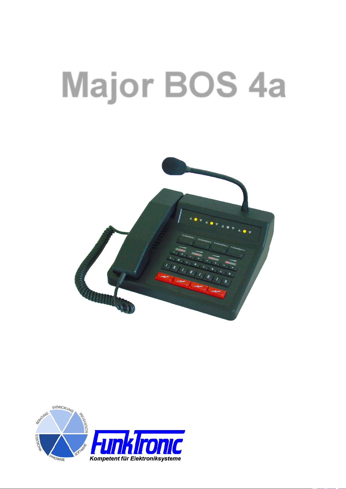
Major BOS 4a
Page 2

mbos4a (25.02.14)
- 3 -
Kompetent für Elektroniksysteme
Table of Contents
Connectivity............................................................................................................................. 4
Control and Display Elements ................................................................................................. 5
Keypad................................................................................................................................. 5
Busy Status LED.................................................................................................................. 5
Transmitter Status LED........................................................................................................ 5
Channel Selection LED........................................................................................................ 5
Loudspeaker / Volume LED Display .................................................................................... 5
Display and Control Elements ................................................................................................. 6
Communication with one Calling Radio Subscriber ................................................................ 7
Channel Selection................................................................................................................ 7
Communicating with the Calling Radio Subscriber.............................................................. 7
Loudspeaker (On/Off status)................................................................................................ 9
Loudspeaker (Volume Control)............................................................................................ 9
Headsets............................................................................................................................ 10
RX-AF-Outputs....................................................................................................................... 11
Encoder ................................................................................................................................. 12
External Signaling Device ..................................................................................................... 12
Transmitter Control................................................................................................................ 12
Audio-Frequency-Connection................................................................................................ 12
Microphone Selection............................................................................................................ 13
Channel Selection ................................................................................................................. 13
Opto-Coupler Input................................................................................................................ 14
Major BOS 4a´s in parallel Circuit ......................................................................................... 15
Activating of the Busy Lines............................................................................................... 15
Scanning of the Busy Lines ............................................................................................... 16
Kompetent für Elektroniksysteme
- 2 -
mbos4a-english (25.02.14)
Page 3

Monitoring-Interface TBBBox4 (optional) .............................................................................. 17
Assigning Channels to the UGA-Modules ......................................................................... 17
Evaluation Functions ......................................................................................................... 18
Tape Control (Switching Contact) ...................................................................................... 19
Service Program.................................................................................................................... 20
Monitor Status.................................................................................................................... 21
Programming Mode EEPROM........................................................................................... 21
EEPROM-Address Layout ................................................................................................. 22
Chart: Jumper and Potentiometer ......................................................................................... 27
Layout.................................................................................................................................... 28
Adjustment Instructions ......................................................................................................... 29
Sockets Pin Layout Connection ............................................................................................ 30
Technical Data....................................................................................................................... 31
General Safety Instructions.................................................................................................... 33
Factory Returning Instructions for old Equipment................................................................. 33
Release Notes....................................................................................................................... 31
mbos4a (25.02.14)
- 3 -
Kompetent für Elektroniksysteme
Page 4
mbos4a (25.02.14)
- 5 -
Kompetent für Elektroniksysteme
Major BOS 4a
Major BOS 4a is a µC-controlled desktop controller unit for 2-way radio systems
controlling up to four radios. Different operating parameters can either be factory preset
or programmed during installation.
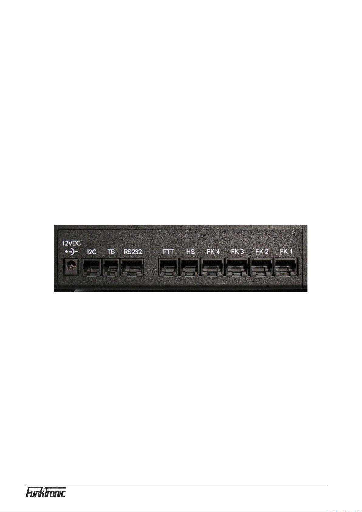
System / Connectivity
The Major BOS 4a is powered by an external +12V-DC power supply.
Up to four channels (radio sets, PA systems -/intercom etc.) can be connected, also
an external handset/headset, up to two external monitoring-interfaces (TBBox4), an
external signal source, a tape recorder and a AF-RX-amplifier for each channel.
Furthermore there is a RS232-connection, to which a terminal can be connected, or a
PC for external control.
There is a squelch input for each radio and also a PTT output, a busy-line,
an AF-input and AF-output. As the TX-AF-outputs are only active while transmitting,
several Major BOS 4a´s can be connected in parallel without any problems.
For detailed pinout see section Sockets Pin Layout Connection.
12VDC power supply connector (12VDC, external, max. 1,5A)
I2CI I²C-Bus
TB Tape recorder
RS232 RS 232 connection
PTT PTT (e.g. foot switch)
HS Headset
FK1 – 4 Transmit / Receive (channel 1 – 4, radio, PA system-/ .
Intercom, etc.)
Also see section Sockets Pin Layout Connection.
Kompetent für Elektroniksysteme
- 4 -
mbos4a-english (25.02.14)
Page 5

Control and Display Elements
Keyboard
The keyboard holds the following functions for each of the four channels:
Funkkreis x Selection button
+ Volume higher
-
L Loudspeaker mute button
S Special function button
I Caller button for encoder 1
II Caller button for encoder 2
PTT button
All buttons can be locked separately
Volume lower
Busy LED
For each of the four radios there is a separate busy LED. To control the busy LED the
carrier input can be switched to ground or to +12V (or an external reference voltage U
The logic of the busy input can be configured separately for each radio with the jumpers
J10 to J13. To change the reference voltage (+12V or U
settings see Chart: Jumper and Potentiometer
) use jumper J5. For jumper
ref
ref
).
TX-LED
For each of the four channels there also is a separate TX LED, which lights up when
the corresponding transmitter is activated. The transmitter is activated by pushing the
PTT button while talking or by transmitting a call. Flashing of the TX LED means that
another Major BOS 4a is using this channel. Also see section Major BOS 4a´s in parallel
circuit.
Channel Selection LED
The channel selection LED (separate for each channel) lights up permanently when the
corresponding channel is selected and activated. Flashing of the channel selection LED
means that this channel has already been selected by another Major BOS 4a. Also see
section Major BOS 4a´s in parallel circuit.
Loudspeaker / Volume LED Display
The loudspeaker / volume display (separate for each channel) is a row of LEDs and indicates the volume setting. If the loudspeaker-AF for the corresponding channel is turned
off the display turns dark.
mbos4a (25.02.14)
- 5 -
Kompetent für Elektroniksysteme
Page 6
mbos4a (25.02.14)
- 7 -
Kompetent für Elektroniksysteme
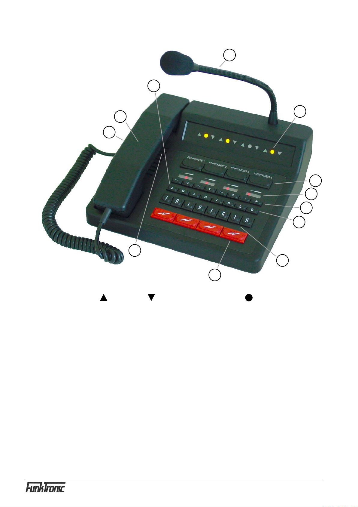
Display and Control Elements
5
12
10
11
1
2
3
4
6
9
7
8
1 - Transmiting- , Squelch- , Selection Status LED
2 - Channel Selection Buttons
3 - Volume Display (row of LEDs)
4 - Volume Control Buttons (+/-)
5 - Loudspeaker Buttons (mute)
6 - Special Function Buttons
7 - Encoder Buttons (I/II)
8 - PTT (for gooseneck or headset microphone)
9 - Loudspeaker
10 - PTT Button (for handset)
11
- Handset
12 - Gooseneck Microphone
Kompetent für Elektroniksysteme
- 6 -
mbos4a-english (25.02.14)
Page 7

Calling a single Radio Subscriber
Channel Selection
To activate one of the four channels push the corresponding selection button. To
deactivate a channel again push the corresponding selection button once more.
Depending on the configuration of the EEPROM-Register 030 in Bit 1 you can either
select several channels simultaneously or only one channel at a time.
Register 030 Number of selectable channels
Bit 1: 0 = several channels simultaneously (cumulative)
1 = only one channel at a time selected
When channels are activated the channel selection LED lights up. If the channel has
already been selected by a different Major BOS 4a the device can be programmed so
that the corresponding channel selection LED flashes.
Also see section Parallel circuit of several Major BOS 4a´s.
!!) In the EEPROM-Register 024 you can preselect which of the channels 1..4 (Bit 0..3)
is automatically selected after turning on the radio installation.
Register 024 selected channels after turning on
Bit 0: Channel 1 No / Yes (0/1)
Bit 1: Channel 2 No / Yes (o/1)
Bit 2: Channel 3 No / Yes (0/1)
Bit 3: Channel 4 No / Yes /0/1)
It is possible to configure the EEPROM-Register 027 so that the selected channels are
automatically saved in the EEPROM-Register 024 when the radio installation is turned
off.
Register 027 Save the selected channels No / Yes (00/01)
Communicating with the Radio Subscriber
There are three different ways of communication with a calling radio subscriber:
a) By pushing one of the red PTT buttons the transmitter of the corresponding channel
is activated on (the corresponding sending status LED lights up) and you can talk to the
caller through the gooseneck microphone. (It is also possible to connect an external switch
contact instead of a PTT button. See section Opto-Coupler input.) If another controlling
device is already transmitting on a channel the Major BOS 4a can be programmed so
that the corresponding sending status LED flashes and optionally the PTT button is
blocked. Also see section Parallel circuit of several Major BOS 4a´s. After depressing
the PTT button the caller can be heard on the loudspeaker. The receiver volume of the
corresponding channel is adjustable, see section Loudspeaker (Volume setting).
mbos4a (25.02.14)
- 7 -
Kompetent für Elektroniksysteme
Page 8

mbos4a (25.02.14)
- 9 -
Kompetent für Elektroniksysteme
b) By picking up the handset and pushing the PTT button on the inside of the
handset. By doing so the transmitter of the selected channel is activated (TX
LED lights up) and you can talk with the caller through the microphone of the
handset.
If another controlling device is already transmitting on a channel the Major BOS
4a can be programmed so that the corresponding TX LED flashes and optionally
the PTT button is blocked. Also see section Parellel circuit of several Major
BOS 4a´s.
Depending on the configuration you can hear the caller constantly on the handset
or only after deactivating the PTT button, see section Loudspeaker.
The call is ended by replacing the handset.
The volume of the earpiece and the microphone are each adjustable by a
potentiometer. The potentionmeter is situated near the earpiece of the handset
and is easily accessible from the outside, using a screw-driver through a small
opening on the inside of the handset.
c) By connecting a compatible handset/headset and pressing the corresponding
PTT button PTT2 (e.g. a foot switch). By doing this the transmitter of the selected
radio channel is also turned on (TX LED lights up) and you can talk with the caller
through the microphone of the handset/headset. (It is also possible to connect
another external switch contact. See section Opto-Coupler input.)
If another controlling device is already transmitting on a radio channel the Major
BOS 4a can be programmed so that the corresponding TX LED blinks and
optionally the PTT button is blocked. Also see section Parallel circuit of several
Major BOS 4a´s.
Depending on the configuration you can hear the caller constantly on the handset
or only after depressing the PTT button, see section Loudspeaker.
After deactivating the PTT button you can also hear the caller on the loudspeaker.
The volume of the corresponding channel is adjustable, see section Loudspeaker
(volume setting).
Kompetent für Elektroniksysteme
The microphone level of the handset/headset can be adjusted with the
potentiometer P10 and the level of its loudspeaker with the potentiometer P12.
!!) After ending the call the activated radio channel can be deactivated by pressing
the corresponding selection button again.
- 8 -
mbos4a-english (25.02.14)
Page 9

Loudspeaker Switching Status
The built in loudspeaker is automatically turned off during transmission.
It is also possible to configurate the EEPROM-Register 02A in Bit 1 so that the
loudspeaker is also turned off automatically when the handset is lifted.
Register 02A Loudspeaker switching status when handset is lifted
Bit 1: 0 = Loudspeaker ON
1 = Loudspeaker OFF
The receiver-AF (on the loudspeaker) of individual radio channels can either be muted
manually by pressing the loudspeaker buttons or automatically when the correspending
busy line is activated (see section Parallel circuit of several Major BOS 4a´s).
If the loudspeaker-AF of a certain radio channel is turned off, the corresponding volume
LED display (row of LEDs) turns dark.
!!) In the EEPROM-Register 025 the loudspeaker switching statuses of the radio channels
1..4 (Bit 0..3) can be preselected after turning on the radio installation.
Register 025 Loudspeaker switching status after turning on
Bit 0: Channel 1 OFF/ON (0/1)
Bit 1: Channel 2 OFF/ON (0/1)
Bit 2: Channel 3 OFF/ON (0/1)
Bit 3: Channel 4 OFF/ON (0/1)
In addition it is possible to make a configuration in the EEPROM-Register 028 so that
loudspeaker switching statuses are automatically saved in the EEPROM-Register 025
when the radio installation is turned off.
Register 028 Saving the loudspeaker switching statuses
No/Yes (00/01)
The EEPROM-Register 02A in Bit 0 can be configurated so that the receiver-AF of all
radio channels (without muting) is switched to the loudspeaker or that the corresponding
radio channels also have to be activated additionally.
Register 02A Receiver-AF on loudspeaker
Bit 0: 0 = all radio channels without muting
1 = only activated radio channels without
muting
Loudspeaker (Volume Control)
The volume of the loudspeaker which is turned on can be set separately with the volume
buttons (+ = higher, - = lower) for each radio channel. The volume level is displayed on
the LED chain.
mbos4a (25.02.14)
- 9 -
Kompetent für Elektroniksysteme
Page 10

mbos4a (25.02.14)
- 11 -
Kompetent für Elektroniksysteme
!!) In the EEPROM-Registers 018...01B the volume settings (´01..´08) for each radio
channel can be preselected separately after turning on the radio installation.
Volume after switching on for
Register 018 Channel 1
Register 019 Channel 2
Register 01A Channel 3
Register 01B Channel 4
In the EEPROM-Register 029 you can also make a configuration so that the selected
volume settings are automatically saved in the EEPROM-Registers 018...01B when the
radio installation is turned off.
Register 029 Save Volume setting No / Yes (00/01)
Earphones
The receiver-AF of the selected radio channel can always be heard on the earphones of
the handset and the headset.
The earphone-AF of individual radio channels can be muted either manually by pressing
the selection buttons or automatically by transmitting on the active or on one of the other
radio channels (earphone muting).
a) In the EEPROM-Register 022 a configuration for the radio channels 1..4 (Bit 0..3)
can be made so that the earphone-AF for the active radio channel is muted while
transmitting.
Register 022 Earphone-AF (while transmitting on the active channel) for
Bit 0: Channel 1 OFF / ON (0/1)
Bit 1: Channel 2 OFF / ON (0/1)
Bit 2: Channel 3 OFF / ON (0/1)
Bit 3: Channel 4 OFF / ON (0/1)
b) In the EEPROM-Register 023 a configuration for the radio channels 1..4 (Bit 0..3)
can be made so that the earphone-AF is muted while transmitting on a different radio
channel.
Register 023 Earphone-AF (while transmitting on a different radio channel) for
Bit 0: Channel 1 OFF / ON (0/1)
Bit 1: Channel 2 OFF / ON (0/1)
Bit 3: Channel 3 OFF / ON (0/1)
Bit 4: Channel 4 OFF / ON (0/1)
Kompetent für Elektroniksysteme
- 10 -
mbos4a-english (25.02.14)
Page 11

RX-AF-Ausgänge
The volume controlled receiver-AF can be tapped individually for each radio channel on
the Major BOS 4a. The outputs can be used e.g. for connecting external AF-amplifier
(per radio channel).
The receiver-AF (for the AF-RX-outputs) of individual radio channels can be muted
either
- manually by pressing the loudspeaker buttons or
- automatically by activating the corresponding busy lines
(see section Parallel circuit of several Major BOS 4a´s) or
- automatically by transmitting on the active or a different radio
channel
There is one Muting-Output per radio channel with which the connected AF-RX amplifier
can be muted when there is no receiver signal (busy??/squelch) (output switches to
GND). See section Sockets Pinout.
a) In the EEPROM-Register 020 a configuration for the radio channels 1..4 (Bit 0..3)
can be made so that the AF-RX-Output is muted while transmitting on the own radio
channel.
Register 020 AF-RX-Output (while transmitting on the active radio
channel) for
Bit 0: Channel 1 OFF / ON (0/1)
Bit 1: Channel 2 OFF / ON (0/1)
Bit 2: Channel 3 OFF / ON (0/1)
Bit 3: Channel 4 OFF / ON (0/1)
b) In the EEPROM-Register 021 a configuration for the radio channels 1..4 (Bit 0..3) can
be made so the AF-RX-Output is muted while transmitting on a different radio channel.
Register 021 AF-RX-Output (while transmitting on a different
radio channel)for
Bit 0: Channel 1 OFF / ON (0/1)
Bit 1: Channel 2 OFF / ON (0/1)
Bit 2: Channel 3 OFF / ON (0/1)
Bit 3: Channel 4 OFF / ON (0/1)
mbos4a (25.02.14)
- 11 -
Kompetent für Elektroniksysteme
Page 12

mbos4a (25.02.14)
- 13 -
Kompetent für Elektroniksysteme
Encoder
The Major BOS 4a has an integrated encoder for ID 1 and ID 2. The calls for each
channel are transmitted directly with the corresponding buttons on the keyboard (I or II).
The ID is transmitted as long as the corresponding button is being pressed.
.
Externel Signaling Device
An external signaling device can be connected to the Major BOS 4a. The sensitivity of
the potential-free inputs can be adjusted with the potentiometer P11.
By activating the corresponding PTT button input (PTT3)the external signal is transmitted
via the selected radio channel.(An additional external switch contact can be connected as
PTT button. See section Opto-coupler input.)
Transmitter Control
The transmitters of the selected radio channels are activated with one of the PTT buttons
(e.g. handset or headset) and stay activated as long as the PTT button is being pressed.
During transmitting the corresponding transmitters are automatically activated.
It is always possible to transmit on non-activated radio channels by using the red PTT
buttons on the control panel.
If another controlling device is already transmitting on a channel the Major BOS 4a can
be programmed so that the corresponding sending status LED flashes and optionally the
PTT button is blocked. Also see section Parallel circuit of several Major BOS 4a´s.
The transmitter control can be switched to ground or to +12V (or an external reference
voltage U
). The logic of the PTT button outputs can be configured separately for each
ref
radio with the jumpers J6 to J9. To change the reference voltage (+12V or U
jumper J5.
By using the Open-collector outputs it is easily possible to connect several Major BOS
4a´s in parallel circuit.
For jumper settings see Chart: Jumper and Potentiometer.
AF-Connection
The audio-frequency-connection is not integrated in the Major BOS 4a anymore. But
by connecting the external headset-adapter the headset can be used as a combined
communicating device for telephone and radio.
The headset is switched to the telephone by an opto-coupler input, which has to be
programmed accordingly (see section Opto-Coupler input).
ref
) use
Kompetent für Elektroniksysteme
- 12 -
mbos4a-english (25.02.14)
Page 13

Microphone Selection
For each of the 3 PTT inputs it is possible to program the corresponding microphone
individually in register 052. Additionally there are two automatic possibilities to detect the
headset. Either the PTT2 input can be programmed as headset detection (programming
register 04C) or the Major BOS 4a can detect if a headset is connected by measuring the
headset supply voltage (programming register 051/052). The threshold level in register
051 has to be set so that the measured supply voltage (at ST10 between Pin 2 and 5)
without headset is higher and with headset is lower than the threshold level. If the PTT2
input is used as headset detection the Major BOS 4a detects the headset when the input
is activated (bridge to ground (GND)). If the Major BOS 4a has detected a headset then
all buttons programmed as SH/HS/PTT use the headset microphone. Otherwise they use
the gooseneck microphone.
Channnel Selection (additionally)
In register 04E you can program whether the loudspeaker is turned on simultaneously
when activating the radio circuit. In register 04F you can program whether the loudspeaker
is turned off simultaneously when deactivating the radio circuit.
mbos4a (25.02.14)
- 13 -
Kompetent für Elektroniksysteme
Page 14

mbos4a (25.02.14)
- 15 -
Kompetent für Elektroniksysteme
Opto-Coupler Input
The Major BOS 4a has an opto-coupler input at connector ST10. This opto-coupler
input can be programmed for different functions.
a) If this register is encoded to value ´00´, the opto-coupler input switches the handset/
headset to the audio-frequency-connection when activated (standard function, see
section Audio-Frequency-Connection).
b) The opto-coupler input can also be used to emulate certain key functions
of the switch panel or to make switching functions for special applications possible.
To do this the assignment to the radio channels is coded at the 1st digit (High-Nibble)
in the EEPROM-register 047. At the 2nd digit (Low Nibble) the key function resp. the
special function which is to be emulated, is encoded:
Register 047 Opto-coupler input
Special function
00 = control the telephone relais
10 = microphone switching for PTT2
PTT2 transmits by gooseneck microphone, when opto coupler is turned on
20 = microphone switching for PTT2
PTT2 transmits by gosseneck microphone when
opto-coupler is turned off
1st digit Assignment to
0 = all activated radio channels
1..4 = radio channel 1..4
2nd digit emulated key / special function
0 = (-no function -)
1 = radio channel (selction)
2 = volume higher
3 = volume lower
4 = loudspeaker ON / OFF
5 = call 2
6 = call 1
7 = transmit (gooseneck microphone)
8 = transmit (microphone of handset/headset)
9 = transmit (external encoder)
A = special functions button
B = transmit (SH or HS-micro), PTT2 selects micro
C = transmit (SH or HS-micro), switching by automatic
headset detection
To activate the opto-coupler input direct current (3V < U < 15V) is necessary. For higher
switching voltages an additional external dropping resistor is necessary (internal dropping
resistor = 1kOhm).
Kompetent für Elektroniksysteme
- 14 -
mbos4a-english (25.02.14)
Page 15

Major BOS 4a's in Parallel Circuit
Several Major BOS 4a´s can be interconnected without any problems as the AF-outputs
are only activated during transmitting and the AF-outputs can be switched to highimpedance by replugging of jumper J1 to J2.
For this purpose all connections with the individual radio channels (TX-AF, RX-AF,
squelch and transmitter PTT) only have to be connected in parallel circuit (bus- or hub
wiring).
Here the busy lines of the radio channels, which can only be connected with the Major
BOS 4a´s , have a special function.
Activating the Busy Lines
Each Major BOS 4a, which is connected to the corresponding busy line, can signalize
to other Major BOS 4a´s in paralle circuit, if a radio channel has already been selected
and/or if a radio channel is already used for transmitting.
a) In the EEPROM-register 02B it is possible to make a configuration for the radio
channels 1..4 (Bit 0..3) so that the corresponding busy line is activated if selected.
Register 02B Activating busy line when channel is selected
Bit 0: Radio channel 1 NO / YES (0/1)
Bit 1: Radio channel 2 NO / YES (0/1)
Bit 2: Radio channel 3 NO / YES (0/1)
Bit 3: Radio channel 4 NO / YES (0/1)
b) In the EEPROM-register 02C it is possible to make a configuration for the radio
channels 1..4 (Bit 0..3) so that the corresponding busy line is activated when transmitting
(on this channel).
Register 02C Activating busy line when transmitting on
Bit 0: Radio channel 1 NO / YES (0/1)
Bit 1: Radio channel 2 NO / YES (0/1)
Bit 2: Radio channel 3 NO / YES (0/1)
Bit 3: Radio channel 4 NO / YES (0/1)
mbos4a (25.02.14)
- 15 -
Kompetent für Elektroniksysteme
Page 16

mbos4a (25.02.14)
- 17 -
Kompetent für Elektroniksysteme
Scanning of the Busy Lines
Each Major BOS 4a, which is connected to the corresponding busy line, detects an
activated busy line and reports this optically to the user as a blinking channel selection
LED or as a blinking TX LED .
This optical display can be configurated in the EEPROM-register 02D for the radio
channels 1..4 (Bit 0..3).
Register 02D Optical busy-LED for
Bit 0: Radio channel 1 as blinking channel selection LED / TX LED (0/1)
Bit 1: Radio channel 2 as blinking channel selection LED / TX LED (0/1)
Bit 2: Radio channel 3 as blinking channel selection LED / TX LED (0/1)
Bit 3: Radio channel 4 as blinking channel selection LED / TX LED (0/1)
You can also configure how the Major BOS 4a treats busy radio channels: e.g. the
transmitter PTT can be disabled and/or the receiver-AF for the loudspeaker (and the RX-
AF output) can be muted:
a) In the EEPROM-register 02E it is possible to make a configuration for the radio
channels 1..4 (Bit 0..3)so that the PTT is disabled when the radio channel is busy.
Register 02E PTT is disabled when the channel is busy
Bit 0: Radio channel 1 NO / YES (0/1)
Bit 1: Radio channel 2 NO / YES (0/1)
Bit 2: Radio channel 3 NO / YES (0/1)
Bit 3: Radio channel 4 NO / YES (0/1)
b) In the EEPROM-register 02F it is possible to make a configuration for the radio
channels 1..4 (Bit 0..3) so that the loudspeaker-AF is muted when the radio channel is
busy.
Register 02F Loudspeaker-AF is muted when the channel is busy
Bit 0: Radio channel 1 NO / YES (0/1)
Bit 1: Radio channel 2 NO / YES (0/1)
Bit 2: Radio channel 3 NO / YES (0/1)
Bit 3: Radio channel 4 NO / YES (0/1)
Kompetent für Elektroniksysteme
- 16 -
mbos4a-english (25.02.14)
Page 17

Monitoring-Interface TBBox4 (Accessories)
The optional monitoring-interface TBBox4 can be looped in to max. 4 radio channels in
order to connect a multi-track voice recorder and/or to interpret or transmit signaling on
the radio channels with the help of a PC if the TBBox4 is equipped with the corresponding
UGA-modules (option)(using a modem).
For this purpose the external PC is connected by the integrated RS232-interface of the
TBBox4.
Together with the Major BOS 4a certain calls like tone sequences or single tones (e.g.
call 1, call 2), which are preprogrammed in the TBBox4, can be evaluated. The evaluation
status is transmitted to the Major BOS 4a by the I²C-Bus (connector ST14).
If the Major BOS 4a is used in bigger systems together with Major BOS 8 units up to
eight radio channels and therefore up to two TBBox4 units can be attached.
In this case, if the 4 radio channels of the Major BOS 4a are to be connected on two
separate TBBox4 units, their control inputs have to be connected to the I²C-Busconcentrator I2C-Con. In this case the I²C-Bus-adresses of the TBBox4 units have to be
coded differently (please ask for advice!). Also see manual Major BOS 8.
For programming the TBBox4 see manuals Monitoring-Interface TBBox4 and Universalencoder/decoder-module UGA00.
Assigning Channels to the UGA-Modules
Each TBBox4 can be equipped with max. 4 UGA-modules, so that up to 8 UGA-modules
are available for decoder functions when 2 TBBox4 units are connected..
The individual radio channel numbers (´01´...´04´) in the EEPROM-registers 031...038
can be assigned freely to these 8 UGA-modules. If no radio channel is to be assigned to
a certain UGA-module set the radio channel number to value ‘00’.
Assigned radio channel number for
register 031 UGA(1)/TBBox4(1)
register 032 UGA(2)/TBBox4(1)
register 033 UGA(3)/TBBox4(1)
register 034 UGA(4)/TBBox4(1)
register 035 UGA(1)/TBBox4(2)
register 036 UGA(2)/TBBox4(2)
register 037 UGA(3)/TBBox4(2)
register 038 UGA(4)/TBBox4(2)
Ex factory the EEPROM-registers 031...034 are programmed in sequence with the radio
channel numbers 01...04 and the EEPROM-registers 035...038 with the value ‘00’ (no
radio channel assigned).
mbos4a (25.02.14)
- 17 -
Kompetent für Elektroniksysteme
Page 18

mbos4a (25.02.14)
- 19 -
Kompetent für Elektroniksysteme
Decoder Functions
Each TBBox4 can be equipped with max 4 UGA-modules, so that up to 8 UGA-modules
are available for decoder functions when 2 TBBox4 are connected.
Each UGA-module can be programmed so that when certain signalings (single tones, tone
sequences) are decoded either one of the two switching outputs DEC1 or DEC2 briefly
(e.g. 1 sec)switches to ground (GND). See manuals Monitoring-Interface TBBox4 and
Universal-encoder/decoder-module UGA00.
The status of the switching outputs DEC1 and DEC2 of all UGA-modules is transmitted to
the Major BOS 4a and causes the loudspeaker-AF of the corresponding radio channels
to be turned on(if it was turned off before):
a) If the switching output DEC2 is turned on because of the UGA-decoding, then the
loudspeaker-AF of the corresponding radio channel is turned on permanently.
b) If the switching output DEC1 is turned on because of the UGA-decoding, then the
loudspeaker-AF of the correspong radio channel is turned on for the duration T. The
duration T can be programmed separately for the radio channels 1..4 in the EEPROM-
registers 03D...040 in steps of seconds (Value coded as HEX-Number in seconds).
Register 03D Radio channel 1
Register 03E Radio channel 2
Register 03F Radio channel 3
Register 040 Radio channel 4
Ex factory the EEPROM-registers 03D...040 are programmed with the Hex-value ‘0A’
(10*1sec=10sec).
Tape Control (switching contact)
The switching contact for controling the tape (Start/Stop) can be configured separately for
each of the two TBBox4 units.
In the EEPROM-registers 039 respectively 03A you can code which radio channels 1..4
(Bit 0..3) control the audio tape switching contact of the TBBox4(1) resp. TBBox4(2).
Register 039 Audio tape switching contact TBBox4(1) controlled by
Bit 0: Channel 1 NO/YES (0/1)
Bit 1: Channel 2 NO/YES (0/1)
Bit 2: Channel 3 NO/YES (0/1)
Bit 3: Channel 4 NO/YES (0/1)
Register 03A Audio tape switching contact TBBox4(2) controlled by
Bit 0: Channel 1 NO/YES (0/1)
Bit 1: Channel 2 NO/YES (0/1)
Bit 2: Channel 3 NO/YES (0/1)
Bit 3: Channel 4 NO/YES (0/1)
Kompetent für Elektroniksysteme
- 18 -
mbos4a-english (25.02.14)
Page 19

Tape Control (Switching Contact) (continued)
The tape control switching contacts are activated with each PTT or squelch/carrier
detection of the corresponding radio channels. After discontinuation of these conditions
they are deactivated automatically after the delay time T.
The delay time T can be programmed separately for the tape control switching contacts
of the TBBox4(1) resp. TBBox4(2) in the EEPROM-registers 03B resp. 03C in steps
of 100ms.
Delay time T = N*100ms (enter as Hex-value!!!)
Register 03B Delay time for tape control switching contact TBBox4(1)
Register 03C Delay time for tape control switching contact TBBox4(2)
Ex factory the EEPROM-registers 03B and 03C are programmed with the Hex-value „32”
(50*100ms = 5sec).
The own tape control switching contact (ST5 / Pin2) is activated as long as one of the two
TBBox4 switching contacts is activated.
mbos4a (25.02.14)
- 19 -
Kompetent für Elektroniksysteme
Page 20

mbos4a (25.02.14)
- 21 -
Kompetent für Elektroniksysteme
Serviceprogramm
The Major BOS 4a has a RS-232-interface with the following specifications:
19200 Baud, 1 startbit, 8 databits, no parity, 1 stopbit
The connectors for the RS-232-interface (RXD, TXD, GND) are located on the 8-pole
RJ45-plug ST15 inside. See section Sockets pin layout.
To use the service program, a simple terminal or a PC with terminal program has to be
connected to this RS-232-interface.
For this purpose the data format resp. the interface has to be set to the above mentioned
specifications.
If Windows is installed on your PC, you can configure the standard Windows terminal
program (e.g. Hyperterminal) accordingly, choosing the option protocol = X on / X off.
(Therfore you only have to connect the three pins RXD, TXD and GND.
If the terminal (or the PC) is connected correctly, you will have access to the service
program and to a range of service commands for:
- programming mode EEPROM
- software reset
To start the service program just enter <return> or <$A2>, <return>. The following text
will appear on the screen:
Online – Monitor PIC 16F877A Software ,MBOS4a`V 2.0
vom (Datum) ( C ) FunkTronic , 01-07
Rxxx Read EEPROM Register xxx
Pxxx_yy Program yy in EEPROM Register xxx
X Reset
#
Please note: the character _ means <space> resp. <blank>.
Kompetent für Elektroniksysteme
- 20 -
mbos4a-english (25.02.14)
Page 21

Monitor Status
The service program may be locked after the device has been turned on (monitor status =
´00`). In this case the service program has to be started by entering <$A2><CR>(=Enter).
Then the monitor menu ( see above) appears on the screen.
If the Major BOS 4a is to be programmed or controlled automatically by a PC or a control
center computer it may be useful for the monitor function to be immediately available
when turned on (monitor status = ´01`or ´02`).
The monitor status can be programmed in the EEPROM-register 026 as follows:
Register 026 Monitor status after turning on
00 = monitor function is turned off
01 = special control function (WED) is turned on
02 = monitor function is turned on
The monitor status (´00`,´01`or ´02`) can also be switched over while operating by
entering <$A0><CR>, <$A1><CR> or <$A2><CR>.
Programming Mode EEPROM
To program an EEPROM-register address <xxx> with the content <yy> proceed as
follows:
1) Start the service program (see section service program)
2) Enter <Rxxx>,<Return> on the terminal.
=> <>xxx: ww> appears on the screen.
3) Now change the desired value (Hex value!!!), so that the new register
is set to <yy> (Hex value!!!).
4) Program the new register content <yy> (Hex value!!!) in the register
address <xxx> by entering the following on the terminal:
<Pxxx_yy>,<Return>(_=<Space>).
5) Check the new register content by means of the on-screen message:
<>xxx: ww ==> yy >.
If instead of a valid address <xxx> the address <999> is entered, all registers are
programmed with the ex factory preset values. A list of all the EEPROM- addresses can
be found in the following section.
Please note (1): Do not change any registers, which are not described in this
manual or whose functions are unclear or unknwon to you.
Please note (2): Almost all adjustable values (e.g. times etc.) of the Major
BOS 4a have to be programmed as HEX numbers. See section
EEPROM-addresses! A conversion chart for HEX numbers can be
found in the attachment!
mbos4a (25.02.14)
- 21 -
Kompetent für Elektroniksysteme
Page 22

mbos4a (25.02.14)
- 23 -
Kompetent für Elektroniksysteme
EEPROM Address Layout
Register Coding for
018 – 01B Volume level after turning on for
018 radio channel 1
019 radio channel 2
01A radio channel 3
01B radio channel 4
020 RX-AF-output (when transmitting on the own channel) for
Bit 0(..3): radio channel 1(..4) OFF/ON (0/1)
021 RX-AF-output (when transmitting on another channel) for
Bit 0(..3): radio channel 1(..4) OFF/ON (0/1)
022 Headset-AF (when transmitting on the own channel) for
Bit 0(..3): radio channel 1(..4) OFF/ON (0/1)
023 Headset-AF (when transmitting on another channel) for
Bit 0(..3): radio channel 1(..4) OFF/ON (0/1)
024 Activated channels after turning on
Bit 0(..3): radio channel 1(..4) NO/YES (0/1)
025 Loudspeaker switching status after turning on
Bit 0(..3): radio channel 1(..4) OFF/ON (0/1)
026 Monitor status after turning on
00 = monitor function is turned off
01 = special control function (WED) is turned on
02 = monitor function is turned on
027 Saving selected channels
NO / YES (00/01)
028 Saving loudspeaker switching statuses
NO / YES (00/01)
029 Saving volume levels
NO / YES (00/01)
Kompetent für Elektroniksysteme
- 22 -
mbos4a-english (25.02.14)
Page 23

EEPROM-Adressen (continued)
Register Coding for
02A 1st digit
Bit 0: Receiver-AF on earphone
0 = earphone-AF ON, when radio and LS are turned on
1 = earphone-AF ON, when radio is turned on
2nd digit
Bit 0: Receiver-AF on loudspeaker
0 = all radio channels without muting
1 = only activated radio channels without muting
Bit 1: Loudspeaker switching status at earphone lift
0 = loudspeaker ON
1 = loudspeaker OFF
02B Activating busy-lines at selected
Bit 0(..3) radio channel 1(..4) NO / YES (0/1)
02C Activating busy-lines when transmitting on
Bit 0(..3) radio channel 1(..4) NO / YES (0/1)
02D Optical busy signal for
Bit 0(..3) radio channel 1(..4) as blinking selection display /
transmitting display (0/1)
02E PTT disabled at busy
Bit 0(..3) radio channel 1(..4) NO / YES (0/1)
02F Loudspeaker-AF muted at busy
Bit 0(..3) radio channel 1(..4) NO / YES (0/1)
transmitting display (0/1)
02E PTT disabled at busy
Bit 0(..3) radio channel 1(..4) NO / YES (0/1)
02F Loudspeaker-AF muted at busy
mbos4a (25.02.14)
- 23 -
Kompetent für Elektroniksysteme
Page 24

mbos4a (25.02.14)
- 25 -
Kompetent für Elektroniksysteme
EEPROM-Adressen (Continued)
Register Coding for
030 Number of selectable radio channels
Bit 0: (-- no function --)
Bit 1: 0 = several radio channels at the same time
(cumulative)
1 = only one radio channel (triggering)
031 – 038 Corresponding radio channel no. for
031 UGA (1)/TBBox4 (1)
032 UGA (2)/TBBox4 (1)
033 UGA (3)/TBBox4 (1)
034 UGA (4)/TBBox4 (1)
035 UGA (1)/TBBox4 (2)
036 UGA (2)/TBBox4 (2)
037 UGA (3)/TBBox4 (2)
038 UGA (4)/TBBox4 (2)
039 Audio-tape switching contact TBBox4(1) controlled
by
Bit 0(..3): radio channel 1(..4) NO / YES (0/1)
03A Audio-tape switching contact TBBox4(2) controlled
by
Bit 0(..3): radio channel 1(..4) NO / YES (0/1)
03B Delay time for audio-tape switching contact
TBBox4(1)
N*100ms (enter as HEX-value!!!)
03C Delay time for audio-tape switching contact
TBBox4(2)
N*100ms (enter as HEX-value!!!)
03D – 040 Loudspeaker activation time at DEC1 for
N*1sec (enter as HEX-value!!!)
03D radio channel 1
03E radio channel 2
03F radio channel 3
040 radio channel 4
Kompetent für Elektroniksysteme
- 24 -
mbos4a-english (25.02.14)
Page 25

EEPROM-Adressen (continued)
Register Coding for
047 Opto-coupler input
Special function
00 = activate telephone relais
10 = switching microphone for PTT2
PTT2 transmits via gooseneck microphone
when opto-coupler is turned on
20 = switching microphone for PTT2
PTT2 transmits via gooseneck microphone
when opto-coupler is turned off
1st digit Assignment to
0 = all activated radio channels
1..4 = radio channel 1..4
2nd digit Emulated key / special function
0 = (- no function -)
1 = radion channel (selection)
2 = volume higher
3 = volume lower
4 = loudspeaker ON / OFF
5 = call 2
6 = call 1
7 = transmit (gooseneck microphone)
8 = transmit (microphone of the handset/headset)
9 = transmit (ext. signal source)
A = special function key
B = transmit (SH or HS-micro), PTT2 switches micro
C = transmit (SH or HS-micro), switch over by
automatic headset detection
04C Headset detection
PTT2 active ==> headset microphone is used
PTT2 inactive ==> gooseneck microphone is used
00 = normal PTT-function, PTT2 is headset-PTT
>00 = PTT2 is headset detection,
SH-micro is open, HS-micro is active
>00 = INP 1-3 and opto-coupler is SH/HS-PTT
(if programmed)
01 = PTT3 is SH/HS-PTT
02 = keyboard-PTT is SH/HS-PTT
03 = PTT3 and keyboard-PTT is SH/HS-PTT
04 = only opto-coupler is SH/HS_PTT
(if programmed)
mbos4a (25.02.14)
- 25 -
Kompetent für Elektroniksysteme
Page 26

mbos4a (25.02.14)
- 27 -
Kompetent für Elektroniksysteme
EEPROM-Adressen (continued)
Register Coding for
04D PTT turns on LS NO / YES (0/1)
1st digit
Bit 0: LS on at call 1
Bit 1: LS on at call 2
2nd digit
Bit 0: LS on when PTT with HA-microphone
Bit 1: LS on when PTT with HS-microphone
Bit 2: LS on when PTT with SH-microphone
Bit 3: LS on when ext. PTT
04E Automatic activating of loudspeaker when radio
channel is activated
Bit 0(..3) radio channel 1(..4) NO / YES (0/1)
04F Automatic deactivating of loudspeaker when radio
channel is deactivated
Bit 0(..3): radio channel 1(..4) NO / YES (0/1)
051 Threshold value for automatic headset detection
threshold value = nn*19,5mV
052 Flags for PTT / automatic headset detection
00 = HS-mic, 01 = SH-mic, 10 = ext. AF,
11 = SH / HS
Bit 0+1: HS – PTT
Bit 2+3: Ext.- PTT
Bit 4+5: SH – PTT
090 – 096 Activating of buttons
Bit 0(..3): radio channel 1(..4) NO / YES (0/1)
090 for button Radio channel
091 for button VOL+
092 for button VOL 093 for button LS
094 for button Call 2
095 for button Call 1
096 for button Transmit (PTT)
Kompetent für Elektroniksysteme
- 26 -
mbos4a-english (25.02.14)
Page 27
Chart: Jumper and Potentiometer
If necessary different configurations and adjustments can be made by using miscellaneous
jumpers. See Layout.
The jumper functions can be seen in the following chart:
Jumper Funktion Position
J1 A RX-AF-input radio channel 1 is 600 Ohm/20kOhm
J1 B RX-AF-input radio channel 2 is 600 Ohm/20kOhm
J2 A RX-AF-input radio channel 3 is 600 Ohm/20kOhm
J2 B RX-AF-input radio channel 4 is 600 Ohm/20kOhm
J6 PTT-output radio channel 1 connects to +Uptt/GND (A+B 1 / A+B 2)
J7 PTT-output radio channel 2 connects to +Uptt/GND (A+B 1 / A+B 2)
J8 PTT-output radio channel 3 connects to +Uptt/GND (A+B 1 / A+B 2)
J9 PTT-output radio channel 4 connects to +Uptt/GND (A+B 1 / A+B 2)
J10 squelch input radio channel 1 active on +12V/GND (A+B 1 / A+B 2)
J11 squelch input radio channel 2 active on +12V/GND (A+B 1 / A+B 2)
J12 squelch input radio channel 3 active on +12V/GND (A+B 1 / A+B 2)
J13 squelch input radio channel 4 active on +12V/GND (A+B 1 / A+B 2)
J5 A +U
ist +12V/ U
PTT
(1 / 2)
ref
Poti Funktion/Pegel
P1 RX-AF for radio channel 1
P2 RX-AF for radio channel 2
P3 RX-AF for radio channel 3
P4 RX-AF for radio channel 4
P5 TX-AF for radio channel 1
P6 TX-AF for radio channel 2
P7 TX-AF for radio channel 3
P8 TX-AF for radio channel 4
P9 Input sensitivity for gooseneck microphone
P10 Input sensitivity for handset/headset microphone
P11 Input sensitivity for external signal source
P12 Earphone-AF for handset /headset
mbos4a (25.02.14)
- 27 -
Kompetent für Elektroniksysteme
Page 28

mbos4a (25.02.14)
- 29 -
Kompetent für Elektroniksysteme
Layout
R128
1
U24
1
U23
8 1
ST1
8 1
ST2
8 1
ST3
8 1
ST4
8 1
ST15
R44
CLK
DATA
VPP
P1
D2
D3
D4
TR2
6 1
ST10
6 1
ST11
C34
B
A
4
1
1
1 2
2
J6
B
A
4
1
1
1 2
2
J9
B
A
4
1
1
1 2
2
J8
B
A
4
1
1
1 2
2
J7
B
A
4
1
1
1 2
2
J13
B
A
4
1
1
1 2
2
J11
B
A
4
1
1
1 2
2
J12
B
A
4
1
1
1 2
2
J10
P3
P2
P4
P8
B
A
4
1
1
12
2
J2
B
A
4
1
1
12
2
J1
P10
P9
P6
C40
P12
C38
P5
P11
C56
1
ST9
C47
P7
C105
C68
C36
C65
C55
C57
C52
R49
C78
C82
1
3
45
6
7
8
2
T2
1
3
45
6
7
8
2
T6
1
3
45
6
7
8
2
T3
1
3
45
6
7
8
2
T5
1
3
45
6
7
8
2
T1
1
3
45
6
7
8
2
T8
1
3
45
6
7
8
2
T4
1
3
45
6
7
8
2
T9
D11
D10
U4
D9
U8
R50
1
3
45
6
7
8
2
T10
R21
R18
R60
R51
R54
R53
R15
R89
R84
R47
R83
R85
R57
R52
R7
R12
R66
R117
R8
R6
R118
R62
R22
R5
R80
R88
R10
R9
R61
R68
R56
R55
R86
R59
R58
R73
R122
R69
R23
R77
R63
R25
R65
R64
R76
R82
R74
R75
R79
R78
R120
R48
R81
R19
R13
R107
R106
R104
R102
R4
R3
R14
R2
R1
R20
R103
R71
R72
R100
R16
R101
R105
R115
R17
R87
R11
R113
R114
R124
R132
R116
R131
R129
R130
R66A
R140
R111
R108
R109
R110
R67
R138
B
A
4
1
1
1 2
2
MP
R24
R112
R37
R38
R39
R40
R41
R34
R32
R33
R31
R35
R28
R27
R127
R126
R125
R30
R36
R46
R26
R121
R123
R29
C26
C37
C39
C74
C4
C70
C60
C71
C7
C66
C73
C79
C35
C58
C77
C45
C96
C88
C42
C20
C12
C43
C19
C44
C24
C41
C21
C11
C8
C72
C94
C63
C61
C93
C106
C90
C64
C3
C15
C46
C5
C13
C2
C80
C17
C76
C10
C6
C91
C9
C97
C23
C99
C102
C92
C100
C103
C101
C104
C22
OK2
1
3
45
6
7
8
2
T7
C18
C14
OK3
OK1
C85
C25
C1
C16
U7
U10
C95
U1
U11
ST13
C62
U5
C67
U13
Q1
U25
D1
U28
1
U12
U22
U14
U6
C98
6 1
ST14
R133
2614
13
1
ST16
C81
+5V
B
A
4
1
1
12
2
J5
1
U9
U3
R95
GND
R92
1
ST12
R45
D14
R94
R93
R91
4
1
ST5
R90
F1
D5
C86
D12
U2
8 1
ST1
8 1
ST2
8 1
ST3
8 1
ST4
8 1
ST15
TR2
6 1
ST10
6 1
ST11
B
A
4
1
1
1 2
2
J6
B
A
4
1
1
1 2
2
J9
B
A
4
1
1
1 2
2
J8
B
A
4
1
1
1 2
2
J7
B
A
4
1
1
1 2
2
J13
B
A
4
1
1
1 2
2
J11
B
A
4
1
1
1 2
2
J12
B
A
4
1
1
1 2
2
J10
B
A
4
1
1
12
2
J2
B
A
4
1
1
12
2
J1
C82
1
3
45
6
7
8
2
T2
1
3
45
6
7
8
2
T6
1
3
45
6
7
8
2
T3
1
3
45
6
7
8
2
T5
1
3
45
6
7
8
2
T1
1
3
45
6
7
8
2
T8
1
3
45
6
7
8
2
T4
1
3
45
6
7
8
2
T10
R117
R118
R107
R106
R104
R102
R4
R3
R2
R1
R103
R100
R101
R105
R111
R108
R109
R110
OK2
1
3
45
6
7
8
2
T7
OK1
C85
D1
6 1
B
A
4
1
1
12
2
J5
4
1
ST5
C86
Jumper Positions (Layout excerpt)
Kompetent für Elektroniksysteme
- 28 -
mbos4a-english (25.02.14)
Page 29

Adjustment Instructions
The AF-levels have already been correctly preadjusted ex factory. If necessary please
follow these instructions.
1) Adjustment RX-inputs (radio channels 1..4) (receiving radio)
a) At the RX-input radio channel 1 (2,3,4) feed in the AF-level
provided by the radio device at 1000 Hz.
b) Select radio channel 1 (2,3,4)
c) Connect the level meter to the RX-AF-output H_Sum (ST15/Pin6)
(GND is MP0).
d) Adjust the level with potentiometer P1 (P2, P3, P4).
The level should be 500mVeff (=-3,8 dBm).
e) After finishing the adjustment:
repeat steps a) to d) correspondingly for the radio channels 2 to 4.
2) Adjustment TX-outputs (radio channels 1..4) (transmitting radio)
a) Connect the level meter and the radio device at the TX-output radio
channel 1(2,3,4).
b) Transmit encoder 1 (1750Hz) on radio channel 1(2,3,4).
c) Adjust the level with the potentiometer P5 (P6, P7, P8).
d) After finishing the adjustment:
repeat steps a) to d) correspondingly for the radio channels 2 to 4.
mbos4a (25.02.14)
- 29 -
Kompetent für Elektroniksysteme
Page 30

mbos4a (25.02.14)
- 31 -
Kompetent für Elektroniksysteme
Steckerbelegung
ST14 ST15ST5PWR
All sockets of the Major shown from rear view.
Layout FK 1- 4 (radio channels)
ST1 - 4
RX-AF-Input (Earphone +) 1
RX-AF-Input (Earphone -) 2
Squelch-Input (Carrier) 3
GND (Ground) 4
Busy Lines 5
(Do not connect to FuG!)
PTT-Output 6
(PTT-Out, Open-Colector max. 100mA)
TX-AF-Output (Mod +) 7
TX-AF-Output (Mod -) 8
The AF- in/ouputs are equipped with transformers and
therefore are potential-free.
Layout TB Audio Tape
ST5
GND (Ground) 1
Audio Tape Switching Contact 2
AF-Output A (Mod. +) 3
AF-Output B (Mod. -) 4
The AF-output A-B is equipped with a transformer and
therefore is potential-free.
ST11
ST10
ST4 ST1ST2ST3
Two connectors for headsets are available. A headset
can be connected to ST13. An external PTT button
(e.g. foot switch) can be connected to ST12.
Layout Headset
ST10
PTT input HS (PTT2, to GND) 1
AF-input HS (micro +) 2
AF-output HS (headset +) 3
AF-output HS-GND (headset -) 4
AF-input HS-GND (micro -) 5
GND (PTT2-Ground) 6
Layout PTT (Headset Switching)
ST11
PTT input, HS (PTT2, to GND) 1
+Batt. Output., Supply Voltage 2
for Headset-Headset Switching PCB
Control Pin 3
for Headset-Headset Switching PCB
Opto-Coupler Input(Anode +) 4
Opto-Coupler Input(Cathode -)
GND (PTT2-Masse) 6
5
Layout RS 232
ST15
TXD (RS232) 1
RXD (RS232) 2
GND 3
PTT-Input 4
ext. Signal Source (PTT3, to GND)
RX-AF-Output LS-Sum 5
(Loudspeaker AF, activated radio channels)
RX-AF-Output H-Sum 6
(Earphone AF, selected radio channels)
AF-Input, ext. Source. Ext_AF (Mod +) 7
AF-Eing. ext. Source. Ext_NF (Mod -) 8
Kompetent für Elektroniksysteme
- 30 -
Layout I2C
ST14
Power Supply. (+12VDC)
Power Sypply. (+12VDC) 2
SDA (I2C-Bus-Data) 3
SCL (I2C-Bus-Clock 4
GND (Ground) 5
GND (Ground) 6
1
Layout Power
PWR
12 VDC, max 1,5 A,
center positive polel, ring GND
mbos4a-english (25.02.14)
Page 31

Sockets Pin Layout (continued)
Connector ST16 for external RX-AF-amplifier
(internal 26-pole latch-connector)
Pin 1 RX-AF-output radio channel 1 LS1 (loudspeaker AF)
Pin 2 RX-AF-output radio channel 2 LS2 (loudspeaker AF)
Pin 3 RX-AF-output radio channel 3 LS3 (loudspeaker AF)
Pin 4 RX-AF-output radio channel 4 LS4 (loudspeaker AF)
Pin 9 – 12 mute switching contact for LS1 to LS4
Pin 13 – 21 GND (ground for RX-AF-outputs)
Pin 25 reference voltage for PTT / SQL
Technical Data
Power supply
Voltage +12V DC-15%+25%
Consumption of current min. 100mA, max. 600 mA
Input level (RX-IN), (from radio channel 1..4)
Ex factory set to 500mV (=-3,8 dBm)
Adjustment range (with potentiometer P1..P4) -8dBM to +3dBm
Input impedance (J1..J4 plugged) 600 Ohm
Input impedance (J1..J4 unplugged) ca. 20 kOhm
Output level (TX-Out), (to radio channel 1..4)
Ex factory set to 500mV (=-3,8 dBm)
Adjustment range (with potentiometer P5..P8) -11 dBm to -1 dBm
Output impedance (when transmitting) ca. 600 Ohm
Output impedance (when receiving) high-ohm (open)
Earphone output level (RX-Out, routed to handset/headset)
Ex factory set to -10 dBm (at 200 Ohm)
Adjustment range (with potentiometer P12) -18 dBm to -8 dBm (at 200 Ohm)
Output impedance ca. 150 Ohm
Microphone input MIC2 (TX-In, Electret, routed from handset/headset)
Ex factory set sensitivity 4 mV(=-46dBm)
Adjustment range (with potentiometer P10) -52 dBm to -41dBm
Input impedance ca. 700 Ohm
AF-input Ext_AF (TX-In, routed from e.g. external signal source)
Ex factory set sensitivity 500 mV (=-3,8 dBm)
Adjustment range (with potentiometer P11) -7 dBm to -1 dBm
Input impedance ca. 20 kOhm
mbos4a (25.02.14)
- 31 -
Kompetent für Elektroniksysteme
Page 32

mbos4a (25.02.14)
- 33 -
Kompetent für Elektroniksysteme
Technical Data (continued)
AF-output LS_Sum
(RX-Out, routed to e.g. external loudspeaker amplifier)
at max. volume -14 dBm (at 600 Ohm)
Output impedance ca. 1 kOhm
AF-output H_Sum
(RX-Out, routed to e.g. external headset)
at selected radio channel -13 dBm (at 600 Ohm)
Output impedance ca. 1 kOhm
AF-outputs LS-i
(RX-Out, routed to e.g. external loudspeaker amplifier)
at max. volume ca. 400 mV (at 10 kOhm)
Output impedance ca. 1 kOhm
Weight ca. 1500 g
Dimensions
(without gooseneck microphone)
Width x depth x height 245 x 220 x 90 mm
Kompetent für Elektroniksysteme
- 32 -
mbos4a-english (25.02.14)
Page 33

mbos4a (25.02.14)
- 33 -
Kompetent für Elektroniksysteme
Please read the operating instructions carefully before installation and setup.
The relevant regulations must be complied to when working with 230V line voltage, two-wirelines, four-wire-lines and ISDN-lines. It is also very important to comply to the regulations
and safety instructions of working with radio installations.
Please comply to the following safety rules:
- All components may only be mounted and maintained when power is off.
- The modules may only be activated if they are built in a housing and are
scoop-proof.
- Devices which are operated with external voltage - especially mains voltage may only be opened when they have been disconnected from the voltage source
or mains.
- All connecting cables of the electronic devices must be checked for damage
regularly and must be exchanged if damaged.
- Absolutely comply to the regular inspections required by law
according to VDE 0701 and 0702 for line-operated devices.
- Tools must not be used near or directly at concealed or visible power lines
and conductor paths and also not at and in devices using external voltage –
especially mains voltage - as long as the power supply voltage has not been
turned off and all capacitors have been discharged. Electrolytic capacitors
can be still charged for a long time after turning off.
- When using components, modules, devices or circuits and equipment the
threshold values of voltage, current and power consumption specified in the
technical data must absolutely be complied to. Exceeding these threshold
values (even if only briefly) can lead to significant damage.
- The devices, components or circuits described in this manual are only
adapted for the specified usage. If you are not sure about the purpose of the
product, please ask your specialized dealer.
- The installation and setup have to be carried out by professional personnel.
Factory returning of old equipment
According to German law concerning electronic devices old devices cannot be disposed off
as regular waste. Our devices are classified for commercial use only. According to § 11 of
our general terms of payment and delivery, as of November 2005, the purchasers or users
are obliged to return old equipment produced by us free of cost. FunkTronic GmbH will
dispose of this old equipment at its own expense according to regulations.
Please send old equipment for disposal to: FunkTronic GmbH
Breitwiesenstraße 4
36381 Schlüchtern
>>> Important hint: freight forward deliveries cannot be accepted by us.
February 2nd , 2006
Subject to change, Errors excepted
General Safety Instructions
Page 34

Release Notes
Modifications made are only mentioned in note form in this section. For detailed
information please read the corresponding chapters.
November 7, 2007 (WP) – compiled (V1.0)
December 21, 2007 (WP) – Pinout of connectors revised (Page 4 / Page 30)
February 25, 2014 – Pinout of connector ST10 revised
Kompetent für Elektroniksysteme
- 34 -
mbos4a-english (25.02.14)
 Loading...