

Page 1

Major BOS 1a
valid for serial number 3000/16
and newer
Page 2

mbos1a - ab3000-16_eng (10.09.2018)
- 3 -
Kompetent für Elektroniksysteme
This manual is valid from serial number: 3000/16 PCB No.: MBOS1A4
Inhalt
page
Abbreviations 2
Control Elements 3
Sockets Pinout Major BOS 1a 4
Rearview of Major BOS 1a 4
Major BOS 1a - General Remarks 5
Talking via the Radio 5
Volume Settings 5
Muting of the Loudspeaker 5
Tone Call Encoder 5
Transmitter Control 6
Connecting several Control Sets in Parallel 6
Headset/PTT 6
Tape Connection 6
External Loudspeaker 6
Connection of TETRA digital radios 6
Potentiometers 7
Jumpers 7
Board Layout (Main) 8
Solder Jumpers on Key Board 9
Board Layout (Keys) 9
Calibrating the AF levels 10
Technical Data 11
General Safety Information 12
Returning of Old Equipment 12
Release Notes 13
Abbreviations
HS HeadSet
BOS Authorities and organizations concerned with public safety
(German: Behörden und Organisationen mit Sicherheitsaufgaben)
TB Tape (German: TonBand)
S/E Radio (German: Sende/Empfangs-Einheit)
PTT Push To Talk
GND GrouND
AF Audio Frequency
ST SockeT
Kompetent für Elektroniksysteme
- 2 -
mbos1a - ab3000-16_eng (10.09.2018)
Page 3

mbos1a - ab3000-16_eng (10.09.2018)
- 3 -
Kompetent für Elektroniksysteme
Control Elements
1
2 3
4
5
6
10
9
1 - PTT Display LED
2 - Operation LED is on if working current is applied
3 - Carrier display, Squelch
4 - PTT button ("SENDEN", red) for gooseneck microphone or headset
5 - Call buttons for Call 1 („RUF 1“, 1750 Hz) and Call 2 („RUF 2, 2135 Hz)
PTT and tone are activated
6 - Volume control for loudspeaker
7 - Loudspeaker
8 - PTT button of the handpiece
9 - Handpiece
8
7
Major BOS 1a is also available without the buttons Call 1 and Call 2.
For customer-specific requirements Major BOS 1a could also be equipped with 3 function keys
(+integrated LEDs) instead of the two Call buttons.
Page 4

mbos1a - ab3000-16_eng (10.09.2018)
- 5 -
Kompetent für Elektroniksysteme
Rearview of Major BOS 1a
ST4, TB (tape, ext. speaker)
ST1, S/E (radio circuit)
ST3, PTT (e.g. foot switch)
ST2, HS (headset)
POWER, 12 VDC, max. 1,5 A
Sockets Pinout Major BOS 1a
All schemes show the sockets viewed from the back of the Major.
Pinout S/E (radio circuit)
ST1
AF input B 1
AF input A 2
squelch input 3
GND 4
output: +12 V, max. 300 mA 5
PTT in/output 6
AF output A 7
AF output B 8
All AF in/outputs are equipped with transformers
and hence potential-free. PIN 5 (+12V) is for supply
of external devices (LIM-AC, FT634C, FT633AC,
FT630).
Attention: Do not use PIN 5 to supply a radio.
300 mA output current is not sufficient.
Pinout PTT
ST3
Pinout HS
ST2
GND 1
AF microphone 2
AF earpiece 3
GND (for earpiece) 4
GND (for mic) 5
PTT, active to GND 6
Pinout TB (tape)
ST4
GND 1
GND (für microphone) 2
AF earpiece 3
GND (for earpiece) 4
AF microphone 5
PTT, active to GND 6
Kompetent für Elektroniksysteme
ext. loudspeaker + 1
ext. loudspeaker GND 2
tape AF output A (mod. +) 3
tape AF output B (mod. -) 4
The AF outputs A-B are equipped with transformers
and hence potential-free.
mbos1a - ab3000-16_eng (10.09.2018)
- 4 -
Page 5

Major BOS 1a - General Remarks
The Major BOS 1a is a µC-based control set for radios allowing the adjustment of different levels and
parameters. The radio is connected to the squelch input, the PTT output and the AF in/output. For
operation 12 V DC supply is necessary.
As the AF output is only open during transmission, several Major BOS 1a can be connected in parallel.
The PTT output can also be used as an input for muting in order to avoid feedback between control
sets placed adjacently to each other.
Talking via the Radio
There are three different ways to talk via a connected radio:
1. by pressing the red PTT button and using the gooseneck or a headset microphone for
voice transmission
2. by using the handpiece and its PTT button
3. by using an external PTT button (e.g. foot switch) for talking via headset or gooseneck
microphone
In all cases the PTT display LED is activated.
Volume Settings
The volume of the loudspeaker (also for ext. loudspeaker) is set via the volume control knob.
The volume of the handpiece as well as the level of its microphone can be adjusted at the handpiece.
The potentiometers are situated near the respective capsules.
The microphone levels for the headset and the gooseneck microphone can be set internally.
Muting of the Loudspeaker
Loudspeaker muting dependencies are configured via JMP4 (see section Jumpers). Ex factory, the
loudspeaker is muted if the red PTT button is pressed, if external PTT is received (secondary device
is connected in parallel) and if the handpiece is taken off.
Tone Call Encoder
The Major BOS 1a has two single tone encoders, Call 1 (1750 Hz) and Call 2 (2135 Hz). The calls
are sent using the respective buttons of the control panel. The tone call is sent as long as the button
is pressed.
Kompetent für Elektroniksysteme
- 5 -
mbos1a - ab3000-16_eng (10.09.2018)
Page 6

mbos1a - ab3000-16_eng (10.09.2018)
- 7 -
Kompetent für Elektroniksysteme
Transmitter Control
The transmitter is switched on with one of the PTT or Call buttons as long as it is pressed. The PTT
output can switch to GND as well as to 12 V. Via the open collector output several control sets can
be connected in parallel.
Connecting several Control Sets in Parallel
As the NF output is only active during transmission and the NF input can be switched to high-resistance,
the connection of several control sets in parallel is possible. Therefor, RJ45 patch sockets can be
used (bus wiring or star wiring).
By decoding the PTT output (in this case used as an input) it is possible to mute the Major BOS 1a
externally in order to avoid feedback between control sets placed adjacently to each other.
Headset/PTT
An external headset with a suitable foot switch can be connected to the 6-pin Western sockets.
The sockets‘ pinout differs only in the polarity of the electret microphone‘s bias voltage in order to
provide the two frequently used pin assignments for headsets with 4/6-pin Western plugs. The two
PTT inputs have different functions. Ex factory, the PTT input at the socket HS allows PTT using the
gooseneck microphone, while the PTT input at socket PTT is for the headset microphone.
Tape Connection
For voice recording a tape recorder can be connected to socket ST4. The output level can be set
internally.
External Loudspeaker
An external loudspeaker can be connected to ST4. The volume is set with the main volume control
knob.
Connection of TETRA digital radios
The Major BOS 1a can also be used with TETRA radios. Via the respective interfaces, Motorola MRTs
(MTM800 FuG / MTM5000er Series, interface FT-Nr. 903070) and Sepura MRTs (SRG3900 via Sepura
Colour Console, interface FT-Nr. 903060) can be connected. Important: For proper function with the
new Sepura interface (PCB-Nr.: MBOSEPA) JMP2b of the Major BOS 1a must be open!
Kompetent für Elektroniksysteme
- 6 -
mbos1a - ab3000-16_eng (10.09.2018)
Page 7
mbos1a - ab3000-16_eng (10.09.2018)
- 7 -
Kompetent für Elektroniksysteme
Jumpers
Jumper Pos. Function
JMP1a 1-2 input impedance AF input 200 ohm, ST1 Pin1-2
JMP1a 2-3 input impedance AF input 600 ohm, ST1 Pin1-2
JMP1a offen input impedance AF input 8 kohm, ST1 Pin1-2
JMP1b 4-5 squelch input +5V-12V, ST1 Pin3
JMP1b 5-6 squelch input GND, ST1 Pin3
JMP1b offen squelch input N/A
JMP2a 1-2 PTT output to +12V, ST1 Pin6 (JMP2b >> 4-5)
JMP2a 2-3 PTT output to GND, ST1 Pin6 (JMP2b >> 5-6)
JMP2a offen PTT output N/A
JMP2b 4-5 PTT input (read back) active high, ST1 Pin6
JMP2b 5-6 PTT input (read back) active low, ST1 Pin6
JMP2b offen PTT input (read back) N/A
JMP3 1-2 headset detection off: always uses gooseneck microphone
JMP3 2-3 headset detection on: uses gooseneck or headset microphone
JMP3 2-5 headset detection off: always uses headset microphone
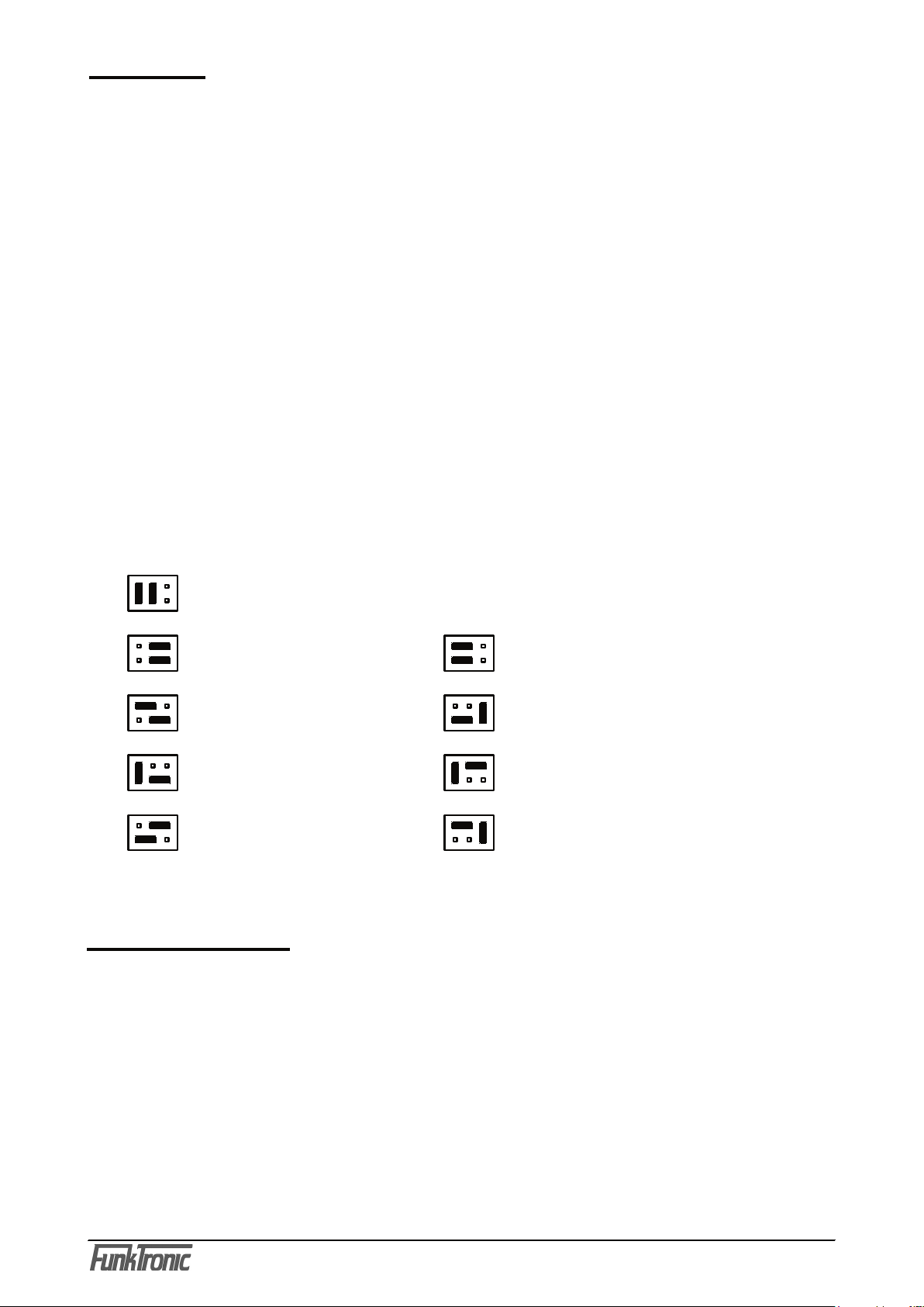
JMP4 LS muting is active, if at least one of the criteria mentioned below is true:
(jumper orientation as depicted in Board Layout on the following page)
as programmed ex factory
(Standard: Muting if PTT pressed or if handset is detached)
no Muting if PTT or
(loudspeaker always on) if handset detached
if (own) PTT if handset detached or
if no squelch
if no squelch if PTT or if no squelch
if handset detached if handset detached or
if PTT or if no squelch
Potentiometers
Poti Function/Level
P1 AF input sensitivity ST1, pin 1-2
P2 AF output total volume ST1, pin 7-8
P3 sensitivity gooseneck microphone
P4 sensitivity headset microphone
P5 volume poti front plate
P6 AF output level tape ST4, pin 3-4
Page 8

mbos1a - ab3000-16_eng (10.09.2018)
- 9 -
Kompetent für Elektroniksysteme
Board Layout (Main)
R57
U12
R58
C6A
R59
1
T3
1
T1
U9
U7
6 1
ST2
4
1
1
1 2
2
JMP1
4
1
1
1 2
2
JMP2
6 1
ST3
D2
D3
D5
D4
R40
R41
R39
C34
C7
4 1
ST4
C30
C15
C12
C28
8 1
ST1
P2
P3
P4
P6
R5
R6
R4R34
R7
R25
R21
R54
R20
R31
R30
R32
R38
R36
R37
R52
R55
R53
R24
R33R29
R1
R35
R18
R10
R9
R44
R42
R45
R43
R27
R26
R2
R3
R11
R28
R23
R19R16
R17
R15
C3
C27
C29
C35
C33
C17
C18
C19
C8
C24
C21
C5
C13
C4
C22
C31
POWER
C36
C9
C6C11
C26
C20
U4
U5
12 1
ST6
C25
C16
P1
1
U6
REL2
REL1
C14
U2
1
T2
D1
C32
4
1
1122
JMP4
C5A
U8
4
1
1
1 2
2
JMP3
R39A
ST5
C23
PRG_DAT
C10
1
ST8
D6
C1
Q1
PRG_CLK
PRG_GND
PRG_5V
PRG_VPP
D7
F1
R12
C2
U1
U3
1
Kompetent für Elektroniksysteme
mbos1a - ab3000-16_eng (10.09.2018)
- 8 -
Page 9

Board Layout (Keys)
PTT
C35
C34
C33
C28
C32
N2
C31
R20
V2
V1
V3
N4
R23
R22
V4
R24
N1
C27
N3
R21
R19
C29
C30
V5
C25
1
ST1B
1
ST1A
LEDKR
LEDSQ
C26
R17
RUF2
R18
RUF3
R13
PRG_DAT
PRG_CLK
PRG_GND
PRG_5V
U3
C11
C15
LEDTX
R16
C21
C24
C23
C20
1
ST5
R6
R7
R4
R8
R5
R15
R9
R12
R10
R1
U7
R3
R2
C6
C5
1
U2
C2
C1
C4
C8
C12
C10
C9
C13
C19
C17
C18
C16
U1
D1
PRG_VPP
JMP1
Q1
U4
U6
1
ST4
121
ST2
U5
C22
RUF1
ST3
C7
C14
Solder Jumpers on Key Board
Jumper Function
N4 closed: max. volume open-end (2,0W, Standard)
open: max. volume limited (1,5W)
V4 closed: loudspeaker is off, if potentiometer is at minimum position
open: minimum volume remains, if potentiometer is at minimum position (Standard)
Remark: For operation with Major BOS 1a, jumpers N1-3 must be closed and jumpers V1-V3 + V5
must be open (factory settings in Major BOS 1a).
Kompetent für Elektroniksysteme
- 9 -
mbos1a - ab3000-16_eng (10.09.2018)
Page 10

mbos1a - ab3000-16_eng (10.09.2018)
- 11 -
Kompetent für Elektroniksysteme
Calibrating the AF levels
The AF levels are calibrated correctly ex factory. If a recalibration is necessary please follow the
steps below:
1) Adjustment of the AF input:
a) apply the AF-level specified by the radio (e.g. 500 mV) at 1000 Hz to the AF input
(ST1/pin1+2)
b) adjust P1 to approx. 530 mV at ST5A/pin1 or ST2/pin 3 or ST3/pin 3
(without load, vs. GND)
c) adjust P6 (Tape) to the desired tape level (norm. 500 mV)
at ST4/pins3+4 (600 Ohm connection)
2) Adjustment of the AF output:
a) connect the level meter and the radio to the AF output. The desired level (e.g.
520 mV at 200 ohm) is the level of the nominal stroke demanded by the radio
b) press button for call 1 (1750 Hz) and adjust desired level with P2
c) adjust the desired level of the gooseneck microphone using P3 while talking
into it normally
d) adjust the desired level of the headset using P4 while talking into it normally
e) adjust the desired level of the handset using the poti near the microphone while
talking into it normally
Kompetent für Elektroniksysteme
- 10 -
mbos1a - ab3000-16_eng (10.09.2018)
Page 11

Technical Data
Operating voltage +12VDC -15% +25%
Current consumption max. 1200 mA, typ. 500 mA
AF input level (ST1, Pin 1-2)
nominal 500 mV at 200 Ohm
adjustment range using poti P1 250 - 1000 mV
input impedance 200 Ohm, 600 Ohm or 10 kOhm, ex factory: 200 Ohm
AF output level (ST1, Pin 7-8)
ex factory 500 mV at 200 Ohm
adjustment range 150 - 630 mV at 200 Ohm
200 - 1000 mV at 600 Ohm
output impedance while transmitting 200 Ohm
output impedance while receiving high-resistance
AF output level (earpiece of headset, ST2+ST3, Pin 3-4)
ex factory 350 mV at 200 Ohm
output impedance ca. 100 Ohm
AF input level (microphone of headset, ST2+ST3, Pin 2-5)
nominal 4 mV
adjustment range (using Poti P4) 2 - 11 mV
input impedance 700 Ohm
AF output level of ext. loudspeaker (ST4, Pin 1-2)
output impedance 4-8 Ohm
AF intensity max. 2 Watt at 4 Ohm
Af output level of tape (ST4, Pin 3-4)
ex factory 500 mV at 600 Ohm
adjustment range 150 - 800 mV at 600 Ohm
output impedance 600 Ohm
Weight ca. 1400 g
Dimension
width x depth x height 245 x 220 x 90 mm, w/o gooseneck microphone
Kompetent für Elektroniksysteme
- 11 -
mbos1a - ab3000-16_eng (10.09.2018)
Page 12

- 12 -
mbos1a - ab3000-16_eng (10.09.2018)
Kompetent für Elektroniksysteme
mbos1a - ab3000-16_eng (10.09.2018)
- 13 -
Kompetent für Elektroniksysteme
Please read the operating instructions carefully before installation and setup.
The relevant regulations must be complied to when working with 230V line voltage, two-wirelines, four-wire-lines and ISDN-lines. It is also very important to comply to the regulations
and safety instructions of working with radio installations.
Please comply to the following safety rules:
- All components may only be mounted and maintained when power is off.
- The modules may only be activated if they are built in a housing and are scoop-proof.
- Devices which are operated with external voltage - especially mains voltage - may only
be opened when they have been disconnected from the voltage source or mains.
- All connecting cables of the electronic devices must be checked for damage regularly
and must be exchanged if damaged.
- Absolutely comply to the regular inspections required by law according to VDE 0701
and 0702 for line-operated devices.
- Tools must not be used near or directly at concealed or visible power lines and conductor
paths and also not at and in devices using external voltage – especially mains voltage as long as the power supply voltage has not been turned off and all capacitors have been
discharged. Electrolytic capacitors can be still charged for a long time after turning off.
- When using components, modules, devices or circuits and equipment the threshold
values of voltage, current and power consumption specified in the technical data must
absolutely be complied to. Exceeding these threshold values (even if only briefly) can
lead to significant damage.
- The devices, components or circuits described in this manual are only adapted for the
specified usage. If you are not sure about the purpose of the product, please ask your
specialized dealer.
- The installation and setup have to be carried out by professional personnel.
Returning of Old Equipment
According to German law concerning electronic devices old devices cannot be disposed off
as regular waste. Our devices are classified for commercial use only. According to § 11 of
our general terms of payment and delivery, as of November 2005, the purchasers or users
are obliged to return old equipment produced by us free of cost. FunkTronic GmbH will
dispose of this old equipment at its own expense according to regulations.
Please send old equipment for disposal to: FunkTronic GmbH
Breitwiesenstraße 4
36381 Schlüchtern
GERMANY
>>> Important hint: freight forward deliveries cannot be accepted by us.
February 2nd , 2006
Subject to change, Errors excepted
General Safety Information
Page 13

Release Notes
- 17.05.2017 Translation of German manual dated from 07.03.2016
- 10.09.2018 Description of connection to TETRA radios
Kompetent für Elektroniksysteme
- 13 -
mbos1a - ab3000-16_eng (10.09.2018)
 Loading...