

Page 1
Major 6a
Page 2

m6a-eng (18.12.2009)
- 2 -
Kompetent für Elektroniksysteme
m6a-eng (18.12.2009)
- 3 -
Kompetent für Elektroniksysteme
Content
Page
Content 2
General Features 3
Display Elements Major 6a 4
Control Elements Major 6a 4
Rear view Major 6a 6
Sockets pin layout Major 6a 6
RS232 Connecting cable for ashing/printing/monitoring 7
Settings RS232 interface 7
Keyboard layout in the programming mode Major 6a 22
Reset 23
EEPROM-addresses 27
EEPROM-addresses (continued) 28
EEPROM-addresses (continued) 29
EEPROM-addresses (continued) 30
EEPROM-addresses (continued) 31
EEPROM-addresses (continued) 32
EEPROM-addresses (continued) 33
Page 3

m6a-eng (18.12.2009)
- 3 -
Kompetent für Elektroniksysteme
The Major 6a is the newer design of the well-known Major 6. The display is an alphanumeric LC display with background lighting. A gooseneck microphone with high dynamics is standard. All keys can
be programmed freely. Two different functions can be assigned to each key.
Up to 4 radios can be connected and used simultaneously by using a multi-core cable (7 cores) for each
radio. There is a squelch input, a PTT output, a potential-free AF input and a potential-free AF output
for each radio.
A headset and a voice recorder (all 4 radio channels merged on one output) can also be connected.
Futhermore there are 3 switching outputs (alarm switching output, recorder control and headset
switching) and a serial interface (RS232 or optional RS485) .
For the exact pinout see section Sockets pin layout connections.
The Major 6a can be programmed by using the keyboard. For displaying a protocol a printer or a terminal can be connected to the serial port.The serial port can also be used for service or special applications.
The Major 6a is automatically turned on if connected to power supply. After turning it on <Funk Tronic
Major 6a> is displayed for a second , then the device is ready for operation.
Hint :
At initial operation the Major has to be leveled to the radio system !
General Features
After turning on the following display appears on the Major 6a
Funk Tronic Major 6a
È
after 2 seconds
no radio circuit active
Page 4
m6a-eng (18.12.2009)
- 4 -
Kompetent für Elektroniksysteme
m6a-eng (18.12.2009)
- 5 -
Kompetent für Elektroniksysteme
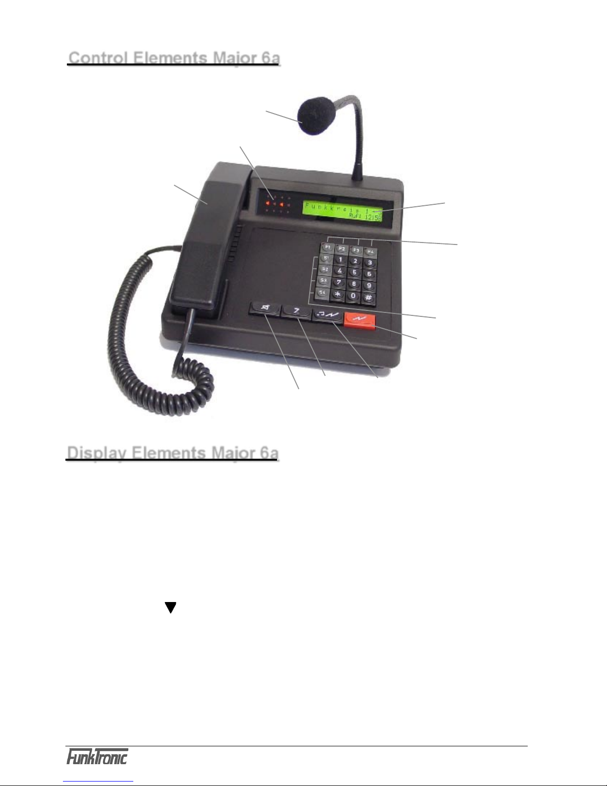
Control Elements Major 6a
Handset
with PTT button
gooseneck microphone
Loudspeaker button
Call button
Short dial button
PTT button
LC-Display
Channel buttons
Special buttons
Status-LEDs
Display Elements Major 6a
LC-Display
All alphanumeric displays are shown on a LC-display with background lighting
(2 lines with 24 characters) .
The display lighting can be configured in the EEPROM-register 009. For programming the
EEPROMs please read the section Programming mode EEPROM-addresses. The display
lighting is turned on ex factory.
Busy LED
The busy LEDs (channels 1..4) are programmed in the EEPROM-register 095 at the digits
1.-4. To control the busy LED any DC voltage between 0V and 1,25V or between 3,75V and 12V
can be used. The operating mode can be configured as follows:
Register 095 1. - 4. digits busy LED
2 = with squelch input < 1,25V (LOW)
4 = with squelch input > 3,75V (HIGH)
Page 5

m6a-eng (18.12.2009)
- 5 -
Kompetent für Elektroniksysteme
TX LED
For each of the four channels there also is a separate TX LED , which lights up when the
corresponding transmitter is activated. The transmitter is activated by pushing a PTT button while
talking or transmitting a call.
Flashing of the TX LED means that another Major 6a is already using this channel (PTTT output
on LOW < 3V).
Loudspeaker LED / Call detection LED
The loudspeaker LED (channel 1..4) lights up when the loudspeaker of the corresponding
channel is activated on operating volume.
A flashing loudspeaker LED means that a call has been detected (call detection LED). The call
detection LED disappears when the corresponding channel is actively used for transmitting, or
when the channel is activated (register 001/2).
F-Buttons (channel buttons) LED
The function of the F-buttons LEDs is programmed in register 001 at the 1st digit.
The LEDs (LEDs in the selection buttons) flash when there is at least one identified call saved in
the identification memory of the corresponding channel. The corresponding LED disappears only
after all identifications have been deleted in the corresponding identification memory.
Also see section Identification Memory - (register 001/1 = 2).
The LED is turned on if the corresponding channel is activated - (register 001/1 = 1)
The LEDs are always turned off - (register 001/1 = 0)
Ex factory programming of the buttons
This specification is valid for the ex factory programming of the buttons.
As all buttons can be programmed freely the functions of the buttons of individually programmed
Major 6a can differ from this description.
Button Function short Function long
F1...F4 channel 1...4 on/off volume control channel 1...4
0...9 call signal button 0... none
S1...S3 none none
S4 last channels on/off adjust headset volume
*
call signal button A channel selection
# displaying the next identification deleting of the current identification
PTT transmitting with gooseneck micro none
CALL transmit selected call as 5-tone transmit return call as 5-tone sequence
sequence
Z select short dial and transmit as none
5-tone sequence
Loudspeaker turn off loudspeaker adjust total volume
Page 6
m6a-eng (18.12.2009)
- 6 -
Kompetent für Elektroniksysteme
m6a-eng (18.12.2009)
- 7 -
Kompetent für Elektroniksysteme
Layout RS 232
ST15
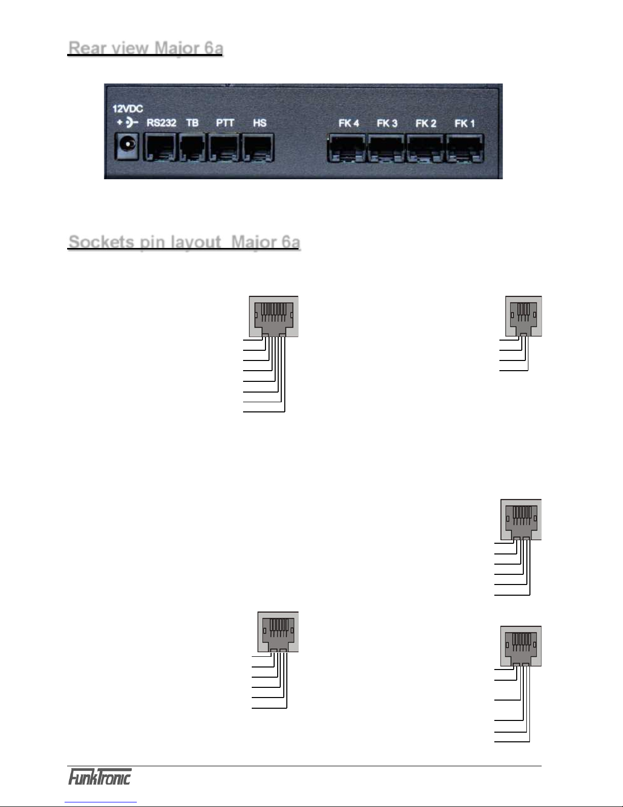
Rear view Major 6a
Sockets pin layout Major 6a
There are two sockets for a headset. The
headset is connected to ST13 and an external
PTT-button (e.g. a foot switch) can be connected
to ST12 or ST13.
All sockets of the Major shown from rear view.
Layout FK 1- 4 (radio channels)
ST1 - 4
RX-AF-input (earphone +) 1
RX-AF-input (earphone -) 2
squelch-input (carrier) 3
GND (ground) 4
output +12V, max. 200mA 5
PTT active low 6
TX-AF-output (Mod +) 7
TX-AF-output (Mod -) 8
The AF- in/outputs are equipped with transformers
and therefore are potential-free. An external device
(FT630-2, FT6304aC) can be powered with contact
5 (+12V) .
Attention: 200mA are not suf cient for a radio.
Layout Power
PWR
12 VDC, max 1,5 A,
center positive pole, ring ground (GND)
Layout TB (audio tape)
ST14
GND (ground) 1
audio tape switching contact 2
AF-output (Mod. +) 3
AF-output (Mod. -) 4
The AF-output is equipped with a transformer
and therefore is potential-free.
Layout PTT (headset switching)
ST12
PTT input (PTT2, to GND) 1
+battery-out., supply voltage 2
for headset switching PCB
control output 3
for headset switching PCB
optocoupler input(anode +) 4
optocoupler input(cathode -) 5
GND (PTT2-GND) 6
Layout HS (Headset)
ST13
PTT input (PTT2, to GND) 1
AF-input (Micro +) 2
AF-output (earphone +) 3
GND AF-output (earphone -) 4
GND AF-input (Micro -) 5
GND (PTT2-GND)
6
ST4 ST1ST2ST3
ST13ST15 ST12ST14PWR
input 1 1
Sw, output 2
TxD 3
RxD 4
GND 5
input 2 6
For protocolling a printer can be connected to
the RS232.
The serial interface can be
laid out as RS485 (option)!
Page 7
m6a-eng (18.12.2009)
- 7 -
Kompetent für Elektroniksysteme
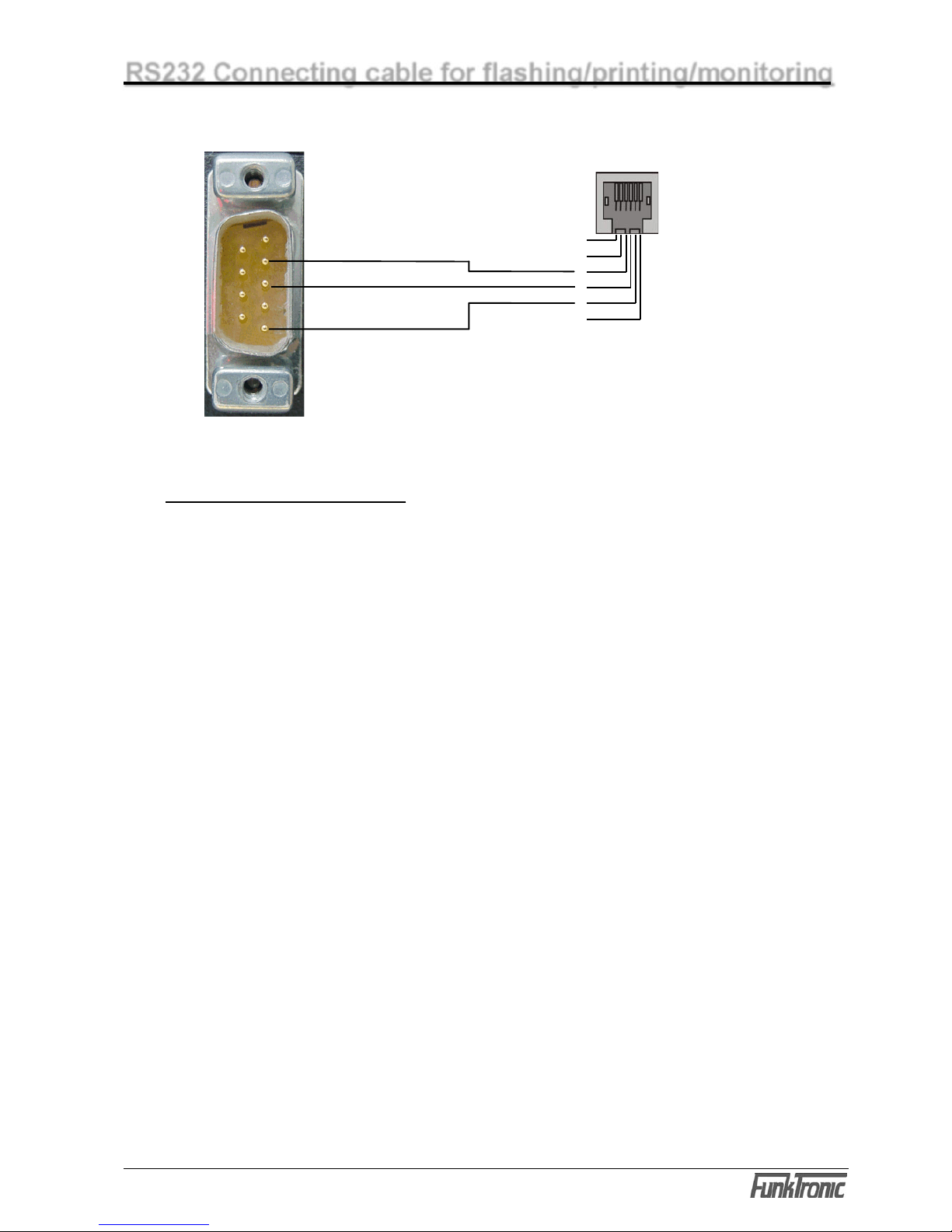
5 GND
RS232 Connecting cable for flashing/printing/monitoring
Pinout
RS232 ST15
1
2
3
4
5
6
TxD
RxD
GND
3 TxD RS232
2 RxD RS232
RS232 9-pole plug at the computer
RS232 connector at the Major
Settings RS232 interface
9600 Baud, 8 databits, no parity, 1 Stopbit, no protocol
Page 8
m6a-eng (18.12.2009)
- 8 -
Kompetent für Elektroniksysteme
m6a-eng (18.12.2009)
- 9 -
Kompetent für Elektroniksysteme
Channel selection
To activate one of the four channels push the corresponding selection button F1 to F4. To
deactivate a channel again push the same or a different selection button. You can also select
several channels simultaneously by keeping the first selected channel button(s) pushed down
while additionally selecting more channels. When channels are activated the corresponding
loudspeaker LED lights up.
Example:
Communicating with the calling radio subscriber
There are three different ways of communicating with a calling radio subscriber:
a) By pushing the red PTT button the transmitter of the selected channel is turned on (the
corresponding sending status LED
lights up) and you can talk to the caller through the
gooseneck microphone.
After depressing the PTT button the caller can be heard on the loudspeaker in regular operating
voulme. The volume of the loudspeaker is adjustable. See section Switching of the loudspeaker
status and Regular operating volume.
b) Or by picking up the handset and pressing the PTT button on the inside of the handset. By doing
this the trasmitter of the selected channel is activated (TX LED lights up) and you can talk with the
caller through the microphone of the handset. You can hear the caller on the handset. The call is
ended by replacing the handset.
The volume of the earphone and the microphone level are each adjustable with a potentiometer.
The potentiometer is situated near the earpiece of the handset and is easily accessible from the
outside by using a screw-driver through a small opening on the inside of the handset.
c) Or by connecting a compatible headset and pressing the corresponding PTT button (e.g. a
foot switch), which has to be connected to the PTT input (connector
ST12/ST13). By doing this
the transmitter of the selected radio channel is also turned on (TX LED lights up) and you can talk
with the caller through the microphone of the headset. You hear the caller on the earphone of the
headset.
The volume can be adjusted with the button S4 (long).
The microphone sensitivity can be adjusted separately for all 3 microphones in the setup menu
„level adjustment“.
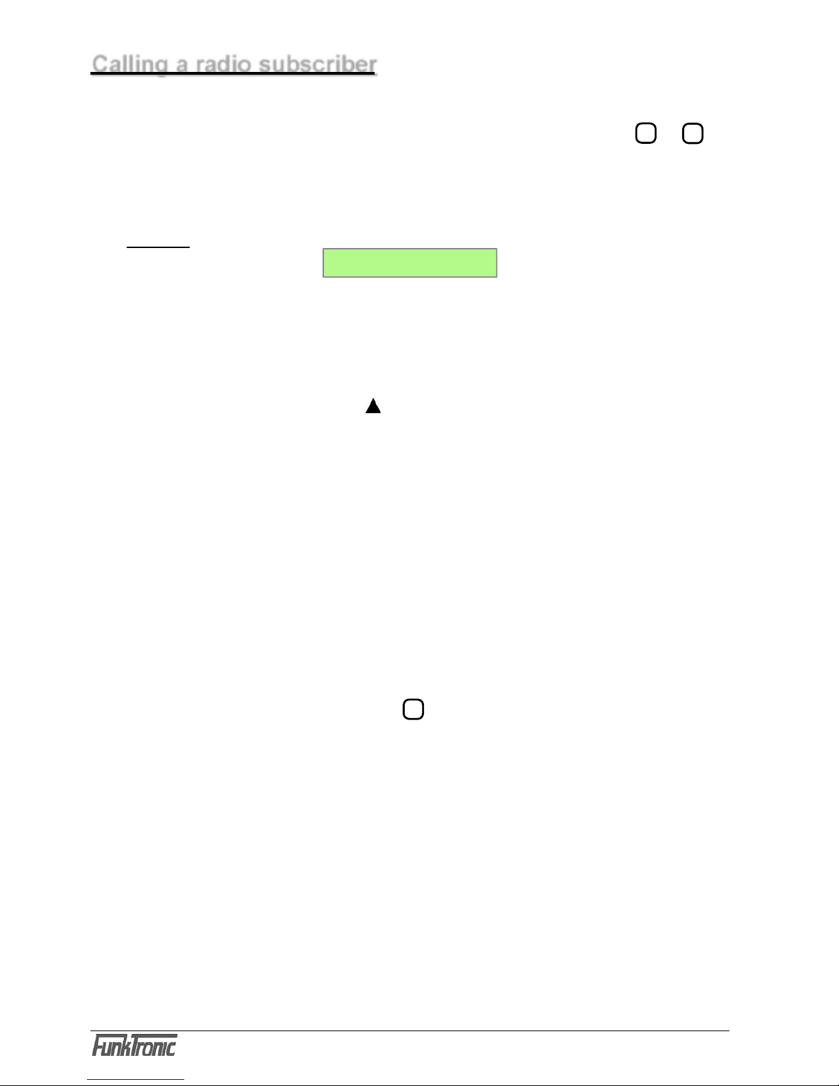
Calling a radio subscriber
C h a n n e l 1 + 2
Call: _
Page 9

m6a-eng (18.12.2009)
- 9 -
Kompetent für Elektroniksysteme
!!) If a PTT button is pushed without having selected a channel, there are two possible reactions
of the Major 6a, depending on the programming of the 3rd digit in the EEPROM-register 001
(0 = latest selected channel; 1 = signal tone) :
a) the latest selected channel is activated automatically. After turning on the radio installation no
channel is activated, so that in this case channel 1 is activated automatically, or
b) a signal tone on the loudspeaker draws the user´s attention to the operating error.
After ending the call the activated radio channels can be deactivated by pressing the corresponding
selection buttons again or by pushing button S4.
Switching of the loudspeaker status
By selecting a radio channel the loudspeaker is switched to the activated channel in regular
operating volume. See section Regular operating volume. If no channel is activated the
loudspeaker can be switched to the latest activated channel(s) in regular operating volume by
pressing button S4.
After that the loudspeaker can switched back to listening volume by pressing the corresponding
selection buttons or button S4. See section Listening-in-volume .
After detecting a call the loudspeaker is automatically switched to the corresponding channel for
an adjustable period of time in the calling volume - unless the channel has already been activated.
See section Calling volume.
The loudspeaker can be muted by shortly pressing the loudspeaker button.
If the receiver is lifted the loudspeaker is automatically muted. By putting down the receiver the
loudspeaker is automatically turned on again.
The possibilty of interconnecting the regular operating or the listening volume to the earphones,
the loudspeaker (and/or the recorder output ) is configurated in the EEPROM-register 000.
Register 000 Configuration for AF interconnections
1st digit RX-AF on receiver / headset
2nd digit RX-AF on recorder output
3rd.digit on loudspeaker, when receiver is put down
4th digit on loudspeaker, when receiver is lifted
5th digit allows RX-AF on loudspeaker during PTT
valid for all digits:
0 = no AF
1 = AF of activated channels
2 = listening in-AF of deactivated channels
3 = AF of acitvated channels and listening in-AF
Page 10
m6a-eng (18.12.2009)
- 10 -
Kompetent für Elektroniksysteme
m6a-eng (18.12.2009)
- 11 -
Kompetent für Elektroniksysteme
Regular operating volume
To change the regular operating volume rst press down the loudspeaker button for a longer time.
The display now shows <Total volume> and next to this on the right side the prompt ashes. The
volume can be set between '0' and '9' . The set volume is saved even after turning off.
But a set power-on-volume can be programmed in register 090/1+2.
Listen-in-volume
If a radio channel is not activated,you can „listen in“ on it with the listen-in-volume. To change
the listen-in-volume (channel x) keep the corresponding selection button F1 to F4 pressed for a
moment. The display now shows <listen-in channel
x : > and the prompt ashes. The volume
can be selected between '0' (listen-in=OFF) and '9' (listen-in-volume=operating volume) . The set
volume is saved even after turning off.
But a set listen-in-volume can be programmed in register 091/1-5.
Call volume
If a channel is not activated the loudspeaker is switched to this channel in call volume for an
adjustable length of time after detection of a call. Then the loudspeaker returns to its previous
status .
The length of time can be encoded for each of the ten decoders in steps of seconds (0..F = 0..15)
in the EEPROM-registers x30 - x39 at the 4th digit.
The call volume of the 10 decoders (channel 1..4) can be programmed between '
0' (call volume
= OFF) and '
9' (call volume = operating volume) in the above mentioned EEPROM-registers at
the 5th digit.
An adjustable volume can be selected with A - F. „A“ meaning the latest set volume , B (+1) to F
(+5) a volume increased by 1 - 5 levels.
It is possible to record calls with the built in recorder/monitoring interface. The interface has a
potential-free AF-output
and a switching contact to ground for controlling the recorder.
The switching contact switches according to the conditions programmed in register 002 at the
4th and 5th digit if:
a) a squelch can be detected on a channel or
b) at least one channel is activated (channel selection LED
lights up) and a squelch can be
detected on this channel (busy status LED lights up) and/or
c) the channel is used for transmitting (TX LED lights up).
After discontinuation of these criteria the contact is turned off with an adjustable delay time
.
This delay time is programmed in steps of seconds in the EEPROM-register 002 at the 1st - 3rd
digit.
Recording of a call
Page 11
m6a-eng (18.12.2009)
- 11 -
Kompetent für Elektroniksysteme
Several Major 6a´s can be interconnected without any problems as the AF-outputs are only activated
during transmitting and the AF-inputs can be switched to high-impedance by disconnecting jumpers
JMP1 / 1 - 4 (see section Layout) .
For this purpose all connections with the individual radio channels (TX-AF, RX-AF, squelch and
transmitter PTT) only have to be connected in parallel circuit (bus- or hub wiring).
The audio-frequency-connection is not integrated in the Major 6a anymore. But by connecting
the external headset-adapter the headset can be used as a combined communicating device for
telephone and radio. The headset is switched to the telephone by an opto-coupler input, which
has to be programmed accordingly (see section Opto-coupler input).
To transmit a call at least one channel has to be activated. If no channel has been selected manually
a signal tone on the loudspeaker draws the user´s attention to the operating error.
Calling by selective call
First at least on channel has to be selected with a selective call. Then the calling code is entered
by using the numerical keys
1 ... 9
. The entry is complete when no prompt flashes anymore. The
call is transmitted with the call button and can be repeated with it.
Calling by short dial
The Major 6a has 10 codeable short dials per channel. The corresponding short dial for an
activated channel is transmitted by shortly pressing the button Z and then entering a number
from '0'...’9' .
The short dials (channel 1..4) are programmed in the EEPROM-registers x00 - x09.
Calling by group call
To be able to use the calling system without any restrictions, the special tone 'A' should be used
as a group call signal. This special tone 'A' is entered with the button * . The group call tone
can be entered at any position. By pressing the call button the call is started and can also be
repeated by using this button.
Major 6a‘s in parallel circuit
Telephone AF-connection
Transmitting of calls
Page 12

m6a-eng (18.12.2009)
- 12 -
Kompetent für Elektroniksysteme
m6a-eng (18.12.2009)
- 13 -
Kompetent für Elektroniksysteme
Calling by collective call /single tone call
It is possible to preselect 9 collective call frequencies (0..8) per channel . The frequency codes of
these single tones are calculated according to this formula
1.008.000
X = ----------------- F [Hz]
and are coded in the UGA(1..4)-registers 000...008 as four digit hex-numbers. Please read the
sections Programming mode UGA and Attachment, Conversion table (...).
Example: collective call 1 (channel 2) has the frequency 2135 Hz, then this results in:
1.008.000
X = ------------------ = 472,13 ==> hex-value = $01D8
2135
therefore UGA(2)-reg. 001 = 01D8.
The corresponding collective call signal (single tone) of the activated channel is transmitted by
pressing a collective call button which has been programmed accordingly.
The number and the duration of the collective call signal 0...8 which is to be transmitted is dened
when programming the button.
Ex factory there is no button programmed for collective call .
Status input
By pressing a status input button programmed for this purpose you get to the status input of
the activated channels. Also see section Transmit call with status. Now you can enter a status
with up to three digits by using the numerical keys 0...9 or you can use the button * to delete a
previously entered status. The input is complete when no prompt ashes anymore. After that the
display returns to the standard display.
Ex factory there is no button programmed for status input.
Return call
If you keep the call button pressed down for a moment the ID (received call) which is currently
shown on the display is transmitted as a call.
Also see section Identication memory.
The return call channel can be adjusted in register 001/5.
Page 13

m6a-eng (18.12.2009)
- 13 -
Kompetent für Elektroniksysteme
Signaling when pressing or depressing the PTT button
The signaling has to be dened in the function of the buttons or the inputs (reg. 010-089).
No signalings have been activated ex factory.
Every time when starting and/or ending using a PTT button the own ID (from/in EEPROMregister x15) and/or a „Roger-Peep“-tone (from/in EEPROM-register x53) can be transmitted
automatically.
An individual „Roger-Peep“-tone can be preselected for each channel. The frequency code of this
single tone is calculated according to the following formula
1.008.000
X = ----------------- F [Hz]
and is coded as a 4-digit hex-number in one of the UGA(1..4) - registers 000-008. Please also
read the sections Programming-mode UGA and Attachment, Conversion table (...).
Example: Roger-Peep tone 0 (channel 3) shall have the frequency 2000 Hz, therefore:
1.008.000
X = ------------------ = 504,00 ==> hex-value = $01F8
2000
therefore UGA(3)-reg. 000 = 01F8.
The duration and the relating single-tone register in the UGA is programmed in register x53.
Page 14

m6a-eng (18.12.2009)
- 14 -
Kompetent für Elektroniksysteme
m6a-eng (18.12.2009)
- 15 -
Kompetent für Elektroniksysteme
Preadjustment of xed tones
It makes sense to program the digits of the tone sequence, which shall not be entered with the
keyboard. These tones can be set at any position of the tone sequence. Therefore it is possible
to x the 1st, 3rd and 5th position. In this case the 2nd and 4th position is entered by using the
keyboard. If there is a sequence of identical tones the repeat tone is automatically inserted at the
correct position. The encoders (channel 1..4) are coded in the EEPROM-registers x10. Also see
section Programming mode EEPROM.
The pre xed tones can always be displayed with the call input, so that different quantities of variable
digitis can be coded for the encoders. If there are several channels activated at the same time
the pre xed tones of the lowest-order channel are used automatically.
The quantity of the displayed tones is programmed in the registers x55 at the 4th digit.
To turn off the tone sequence encoder use the programming EEEEE.
Transmitting a call with ID
IDs (channel 1..4) are coded in the EEPROM-registers x15 . (Normally the ID has the same
code as the encoder 1, but if necessary a different code can be chosen.)
Depending on the con guration the ID is automatically transmitted before or after each call or short
dial, and either a connecting tone or a rest with adjustable duration is inserted between the two
tone sequences of a double sequence. The duration is coded in steps of 5ms in the corresponding
UGA(1..4)-register 243 at the 1st+2nd digit (hex-value !) . The connecting tone resp. the rest
(0..E = tone 0..E; F = rest) is coded at the 5th digit for the button and enter functions - function
2 (transmit call).
If the ID mode is used with 6-, 7- or 8-tone sequences, the last 1 -3 digits of the ID are attached
to the call number.
Transmitting a call with status
The status selection is con gurated in the EEPROM-register 005 at the 1st digit . If no status
selection is necessary please code this position with '
0'. The status can be con gurated with up
to three digits and is attached to the end of each 5-, 6-, 7- or 8-tone sequence (not for double
sequences !), and the length is increased by up to three digits. If the ID mode is used with 6-, 7-
or 8-tone sequences, an 8-tone sequence for example is turned into a 10-tone sequence when
there is a 2-digit status selection.
For information on status input see section Transmitting calls.
register 060 1st digit 0 = no status selection
1...3 = number of digits for status selection
Con guration of the tone sequence encoder
Page 15

m6a-eng (18.12.2009)
- 15 -
Kompetent für Elektroniksysteme
The Major 6a can identify up to 10 different decoder programmings per channel. The IDs of the
10 decoders (channel 1..4) are coded in the EEPROM-regi sters x20-x29 . Decoders which are
not needed have to be coded at the 1st + 2nd digit with 'E' or at the 8th digit with '0'.
The con guration can be adjusted separately for each decoder of the 4 channels in the EEPROM-
registers x30-x49. The following features can be con gured:
- call tone
- call volume
- ID-mode
- alarm switching output and its activation time
- acknowledgement mode
For simplicity the following information always refers to decoder1 of channel1, the con guration
of which is programmed in the EEPROM-registers 130+140 . All other decoders (if needed) are
programmed in the same manner.
Decoder (1)
The decoder1 of channel1 is coded in the EEPROM-register 120 at the digits 1-7. Please also
read section Programming mode EEPROM. Variable tones and tones which are not used, have
to be programmed with 'F'.
Each received tone sequence is compared with the programming of the decoder, and every tone
of the tone sequence at the positions coded with an 'F' is accepted.
The decoder can be activated or deactivated at the 8th digit in register 120.
After the correct identi cation of the tone telegram the ID (if available) is saved (if con gured), the
con gured acknowledgement is transmitted, the loudspeaker is activated with the call volume (if
the channel has not already been activated) and the con gured call tone is started.
If double sequences are used the acknowledgement is delayed by 1 second max. . Also see
Identi cation memory.
There is no additional check of the tone sequence by decoders with higher indices. Principally
decoder1 has the highest priority and decoder 10 the lowest when decoding a telegram.
Call tone
The sound of the call tone can be con gured separately for each decoder of each channel in the
EEPROM-registers x30-x39 at the 1st digit.
You can choose between 10 different types of call tones '
1'...'9' and 'A' . The types 1-5 can be
repeated up to 9 times. For this the 1st digit has to be programmed with '
B' (type 1) ... 'F' (type
5). If you don´t want a call tone program '0' at this digit.
The duration of the call tone can be programmed in the above mentioned EEPROM-registers at
the 2nd digit in steps of 200ms (0,2...3 sec / 0=in nite) and the volume of the call tone can be
programmed at the 3rd digit(0..9, A...F).
0 - 9 = set volume
A = actual volume
B - F = actual volume + 1(B) - 5(F) steps
Receiving calls
Page 16

m6a-eng (18.12.2009)
- 16 -
Kompetent für Elektroniksysteme
m6a-eng (18.12.2009)
- 17 -
Kompetent für Elektroniksysteme
ID-mode
The ID-mode for each decoder can be coded separately in the EEPROM-registers x40-x49 at
the 1st digit. (Also see EEPROM-addresses)
register x40 - x49
1st digit ID-mode
0 = 5 tone sequence
1 = call, ID (double sequence) (3-7 tone sequence)
2 = ID, call (double sequence) (3-7 tone sequence)
3 = 6 tone sequence
4 = 7 tone sequence
5 = 8 tone sequence
6 = 3-7 tone sequence without ID
7 = 5 tone sequence without ID
8 = 4 tone sequence
9 = 3-7 tone sequence
A = emergency call 5 tone sequence
B = emergency call 5 tone sequence ZVEI
D = emergency call 2 x 5 tone sequence (forest emergency call)
The tone duration of the 3-7 tone sequences is programmed in
register x55 at the 4th digit.
2nd digit switching output
0 = none
1 = switching output ST 15/2
2 = tape switching output ST 14/2
3 = headset switching output ST 12/3
3rd digit switching output (0 = off, F = on, 1 - D = 1 - 13s activation
time)
4th digit acknowledgement
0 = none
1 = acknowledgement
3 = own ID
4 = received ID
5th digit loudspeaker / activate LED
(0 = no, 1 = loudspeaker, 2 = LED, 3 = loudspeaker + LED)
6th digit emergency call ag for 3-7 tone sequences
(only for ID-Mode: 1, 2, 9)
0 = regular call - no emergency call
1-7 = emergency call, display 1 - 7 digits from the right
Between the two tone sequences of a double sequence either a connectiong tone B or a rest
can be inserted. The rest can be omitted. If so the two tone sequences are transmitted directly one
after the other (instead of a 2x 5 tone sequence, it is then a 1x 10 tone sequence).
Alarm switching output
The Major 6a has 3 possible alarm switching outputs. But the switching outputs 2 and 3 also have
other functions which then cannot be used.
After the identication of a correct tone sequence by a decoder the chosen switching output (see
above mentioned 2nd digit) is activated for N seconds. The acitivation time N can be congured
for each decoder (channel 1..4) separately in steps of seconds in the EEPROM-registers x40
- x49 at the 3rd digit.(see above).
Page 17

m6a-eng (18.12.2009)
- 17 -
Kompetent für Elektroniksysteme
Acknowledgement
After the correct identication of a tone sequence by a decoder either no acknowledgement,
a standard acknowledgement, the own ID or the received ID is transmitted, depending on the
conguration.
The standard acknowledgements (channel 1..4) are programmed in the EEPROM-registers x17
and the own IDs are coded in the EEPROM-registers x15.
The acknowledgement mode can be coded for each decoder separately in the EEPROM-registers
x40-x49 at the 4th digit:
register x40 - x49
4th digit Acknowledgement mode decoder
0 = no acknowledgement
1 = standard acknowledgement
3 = own ID
4 = received ID
Group call decoder
A group call decoder for tone A (or 0) can be implemented with every decoder by coding the group
call signal A (or 0) at the desired digit in the tone sequence of the corresponding decoder.
As no acknowledgment can be transmitted, the 4th digit in the corresponding conguration register
2 has to be coded with '0'. Also see sections Acknowledgement and Programming mode
EEPROM.
Example:
A group call decoder is to be realized with decoder 3 (channel 2) for the sequence
'1 2 1 0 A’ (group of 10). To do this the following registers have to be programmed as follows:
register 222 = 1 2 1 0 A F F 1
register 242 = 0 x x 0 x 0 0 0
Collective call decoder
The collective call decoder (channel 1..4) decodes single tones of a certain length of time. This
length of time can be dened in steps of 5ms in the UGA(1..4)-register 245 at the 1st + 2nd
digit for special call signals and at the 3rd + 4th digit for tone sequence signals.
After decoding the loudspeaker is turned on with call volume (if the channel has not yet been
activated), the congured call tone is started and the programmed acknowledgement is transmitted.
The group call decoder is programmed in the EEPROM-registers x84 and x85.
The group call decoder can either decode a tone from a tone sequence or a special call signal. The
tone which is to be decoded is programmed at the 1st digit (0-E for a tone of a sequence 0-E, 1 or
2 for call 1 or call 2). For decoding a tone of a tone sequence the 2nd digit has to be programmed
with 0-3. For decoding a special call signal the 2nd digit has to be programmed with 8-B.
Page 18

m6a-eng (18.12.2009)
- 18 -
Kompetent für Elektroniksysteme
m6a-eng (18.12.2009)
- 19 -
Kompetent für Elektroniksysteme
In register 001 at the 4th digit you can program if a common identi cation memory (20 IDs) or
4 identi cation memories per channel (5 IDs each) is/are to be used. The identi cation memories
can be adapted to the corresponding application. If all memory IDs are occupied, the memory is
refreshed and the oldest ID is dropped.
After selection of a channel the saved identi cations can be scrolled by using the key # (press
shortly).
The displayed ID can be deleted from memory by using the key # (press long) or the ID can be
transmitted as a return call by pressing the call button for a longer time.
If the fo-function is activated the oldest ID is displayed with the identi cation memory
-button
and only after deleting the next ID it moves up. The fo-function is programmed in the
EEPROM-
registers x86 at the 2nd digit.
(0 = OFF, 1 = ON).
The identi cation memory can be used for all ID-modes with ID (0-5, 8, 9).? See section Receiving
call, ID-mode.
The ID digits for the ID-modes 3-5 are de ned (5 tone sequence + 1-3 digit ID). For the other IDmodes the key tones are used for the identi cation memory.
Key tones
The key tones are coded in the EEPROM-registers x16. The coding of the key tones selects the
IDs, which are saved, and determines which digits of the ID are shown on the display. The digits
at which all tones are allowed and which are later shown on the display and all unused digits have
to be coded with 'F'. Please also read section Programming mode EEPROM.
Memory refresh
If a new ID is received there is a checkup to see if the same ID already exists in the memory. If the
ID has already been saved and the refresh function is not activated, the received ID is dropped. If
the refresh function is activated the ID is deleted at the former position and is saved again at the
rst position. The identi cation memory is always arranged chronologically. The refresh function
is programmed in the EEPROM-registers x86 at the 1st digit (0 = OFF, 1 = ON). Also see
Programming mode EEPROM.
Example:
In the following example an identi cation memory is con gured for channel 3, which saves every
ID beginning with '1 2 1'. The identi cation memory is to be refreshed and the fo-function is turned
off:
register 316 value
1st - 5th digit 121FFFFF
register 386 value
1st digit 0 = refresh function OFF
1 = refresh function ON 1
2. digit 0 = fo-funcion OFF 0
1 = fo-function ON
IDs are only entered in the identi cation memory if they have been decoded by a decoder whose
ID-mode has an ID.
Identi cation memory
Page 19

m6a-eng (18.12.2009)
- 19 -
Kompetent für Elektroniksysteme
Tone sequence parameter for encoder and decoder
Tone duration (encoder)
The duration of the 1st tone (channel 1..4) is de ned in the UGA(1..4)-register 244 at the 1st and
2nd digit. The duration of the other tones (channel 1..4) is adjustable in the
UGA(1..4)-register
244 at the 3rd and 4th digit. The values can be con gured in steps of 5ms and are encoded
to their exact speci cations. Please refer to the section Tone chart for the programming of the
different tone durations. The duration of the rst tone may differ from the other tones. For example:
tone duration 1st tone = 1000ms and 2nd to 5th tone = 70ms.
Tone duration (decoder)
Certain tolerances have to be allowed when decoding a tone sequence so that unexact tone
telegrams can be decoded reliably.
The minimal duration of each tone of a tone sequence (channel 1..4) is de ned in the
UGA(1..4)-
register 241 at the 1st and 2nd digit. The maximum duration of the 1st tone (channel 1..4) is
adjusted in the UGA(1..4)-register 242 athe 1st and 2nd digit. The maximum duration of the
other tones (channel 1..4) is adjustable in the UGA(1..4)-register 242 athe 3rd and 4th digit. The
values are selectable in steps of 5ms. The tone sequence and the given tolerance determine the
minimum and maximum tone durations. The recommended tolerance is about +/- 25%. Please
also read section Tone chart.
Tone sequence
The tone sequence (channel 1..4) is selected in the UGA(1..4)-register 240 at the 2nd digit. See
the following chart.
The duration of a tone is not automatically changed when selecting a tone sequence. If, for example,
there is a change from "ZVEI1" to "CCIR" the tone duration has to be newly de ned. Please also
read the sections Tone duration (...).
UGA-register 240 2nd digit tone sequence
0 = ZVEI 1 (ex factory)
1 = CCIR
2 = ZVEI2
3 = EEA
Page 20

m6a-eng (18.12.2009)
- 20 -
Kompetent für Elektroniksysteme
m6a-eng (18.12.2009)
- 21 -
Kompetent für Elektroniksysteme
Tone chart
Tone ZVEI 1 CCIR ZVEI 2 EEA
0 2400 Hz 1981 Hz 2400 Hz 1981 Hz
1 1060 Hz 1124 Hz 1060 Hz 1124 Hz
2 1160 Hz 1197 Hz 1160 Hz 1197 Hz
3 1270 Hz 1275 Hz 1270 Hz 1275 Hz
4 1400 Hz 1358 Hz 1400 Hz 1358 Hz
5 1530 Hz 1446 Hz 1530 Hz 1446 Hz
6 1670 Hz 1540 Hz 1670 Hz 1540 Hz
7 1830 Hz 1640 Hz 1830 Hz 1640 Hz
8 2000 Hz 1747 Hz 2000 Hz 1747 Hz
9 2200 Hz 1860 Hz 2200 Hz 1860 Hz
A 2800 Hz 2400 Hz 886 Hz 1055 Hz
B 810 Hz 930 Hz 810 Hz 930 Hz
C 970 Hz 2247 Hz 740 Hz 2247 Hz
D 886 Hz 991 Hz 680 Hz 991 Hz
E 2600 Hz 2110 Hz 970 Hz 2110 Hz
Duration ZVEI 1 CCIR ZVEI 2 EEA
min. 52.5 ms 75 ms 52.5 ms 30 ms
typ. 70 ms 100 ms 70 ms 40 ms
max. 87.5 ms 125 ms 87.5 ms 50 ms
Tone chart
Page 21

m6a-eng (18.12.2009)
- 21 -
Kompetent für Elektroniksysteme
Transmitter control
The transmitter of the selected channel is activated with one of the PTT buttons and stays activated
as long as the PTT button is being pressed. During transmitting of the call the transmitter is
automatically activated.
The transmitter is controlled by open-collector-outputs to
GND, so that several Major 6a´s can be
connected in parallel circuit without any problems.
PTT button lead time
The lead time is de ned as the time between the activation of the transmitter and the interconnection
of the AF-signaling to the transmitter.
The lead time (channel 1..4) is programmed in the UGA(1..4)-register 243 at the 3rd + 4th digit
in steps of 5ms. Ex factory the lead time is adjusted to 200ms.
The remote control of radio devices can only be used togther with our Line-Interface FT634aC/
CL. For each channel which is to be connected to a remote radio device a separate pair of LineInterfaces FT634aC/CL
(one for Major 6a and one for a radio device) is needed.
To get to the channel input mode of an activated channel press the button * (push long). The
display switches to the channel display and the prompt of the channel number blinks on the
right side of the dispaly. The channel can be entered with one or two digits, depending on the
programming in the EEPROM-registers x66 at the 1st digit
(0 = no/none 1 = one-digit, 2 = twodigit channel selection). Now you enter the new channel with the numerical keys. After the number
is completely entered there is a checkup to see if the entered channel is in the valid range. This
range is programmed in the EEPROM-registers x65 at the 1st -4th digit. If the channel is valid
the channel is automatically switched (channel switching telegram is transmitted) and the previous
display status is restored.
If no acknowlgedgement is received from the connected AC-control (radio device end) (1st and
2nd digit of the telegram must be swapped), the channel switching telegram is repeated up to two
times. If no acknowledgement is then received the display shows <Channel x interrupted> .This
display can only be deleted by pressing the button # .
The encoder-IDs for the remote channel control are coded in the EEPROM-registers x63/1-3.
In the EEPROM-registers x6
at the 2nd digit you can con gure if the PTT ouput is turned on or
off during the channel switching telegram (
6 = without PTT, 5 = with PTT).
Please note: remote channel without PTT can only be used if the AF-in-out of the
FT634aC
(Major 6a end) in idle mode is connected to the line. This requires the receiver (RX) AF-in-out
of this
FT634aC to be switched by decoding the pilot reference (3300 Hz). This means that the
FT634aC (radio device end) has to generate this pilot reference if a squelch is present (and when
acknowledging)!
Remote channel operation
Page 22

m6a-eng (18.12.2009)
- 22 -
Kompetent für Elektroniksysteme
m6a-eng (18.12.2009)
- 23 -
Kompetent für Elektroniksysteme
You reach the menu by pressing the key * and the key # at the same time.
The operation of the Major 6a is described below.
Function Major 6a key
next menu F3
select menu item F4
exit without change F3
save and exit F4
increase value by 1 F2
decrease value by 1 F1
Menu structure
Keyboard layout in the programming mode Major 6a
The key F1 decrements by 1 and the key F2
increases by 1.
The keys S1 to S4, the key * and the key # represent the values A to F.
¡
1
3
5
4
8
2
0
9
*
7
6
#
A
E
F
+
-
S1
¡
B
S2
¡
C
S3
¡
D
S4
Page 23

m6a-eng (18.12.2009)
- 23 -
Kompetent für Elektroniksysteme
Reset
- enter the register you
want to program here
Reset
999 programs the factory
setting
Reset
- update the code with the
desired value
* and #
È
Æ
Æ
È
È
- is displayed for 3 seconds
F3=quit menu without change
F4=save value and exit
EEPROM programing : F4
next menu : F3
software version : F4
next menu : F3
UGA programing : F4
next menu : F3
register:
software: Major 6a V 1.0
date : 19.01.07
register: 000
code 12345678
c h an n e l 1 + 2
call: _
È
enter UGA-number : 1
È
e.g. 1
UGA 1 register: _ _ _
È
e.g. 123
UGA 1 register: 123
code: FFFF
- update the code with the
desired value
F3=quit menu without change
F4=save value, and exit
Programming mode
Page 24

m6a-eng (18.12.2009)
- 24 -
Kompetent für Elektroniksysteme
m6a-eng (18.12.2009)
- 25 -
Kompetent für Elektroniksysteme
* and #
È
Æ
basestation 1 + 2
call: _
1 = IN-input level
2 = OUT-output level
3 = GN-microphone level**
4 = HA-microphone level **
5 = HS-microphone level **
6 = VR-output level
È
- the adjustment range of
the potis is 0-255
- input directly on keyboard
or
F2 = increase value by 1
F1= decrease value by 1
level settings : F4
next menu : F3
Poti-no. (1-6):
IN OUT GN HA HS VR
È
channel (1-4):
inputlevel nominal=500mV
F3 = quit without change
F4 = save value, exit menu
0 = 200 Hz
1 = 300 Hz
2 = 400 Hz
3 = 600 Hz
4 = 800 Hz
5 = 1000 Hz
6 = 1600 Hz
7 = 2400 Hz
8 = 3400 Hz
9 = 4000 Hz
S1 = 2900 Hz
S2 = 3000 Hz
S3 = 3100 Hz
S4 = 3300 Hz
* = 1200 Hz
# = 1800 Hz
Z = exit menu
È
Æ
È
F2 = increase value by 1
F1= decrease value by 1
Transmit test tone : F4
next menu : F3
change frequency 0.....F
Z for ESC Hz
adjust contrast : F4
next menu : F3
display contrast: 90
F1- F2+ F3Exit F4end
F3 = quit without change
F4 = save value, exit menu
**
GN = gooseneck
HA = handset
HS = headset
VR = Voice Recorder
Page 25

m6a-eng (18.12.2009)
- 25 -
Kompetent für Elektroniksysteme
* and #
È
Æ
c h a n n e l 1 + 2
call: _
È
F1 = one digit to the left
F2 = one digit to the right
The values can be changed
directly with the keys 0 to 9 .
set date/time : F4
next menu : F3
15.10.07 22:47:01
F3 = quit without change
F4 = save value, exit menu
The clock has already
been calibrated ex factory.
Note the values for digital
and analog. Higher values
accelerate, lower values
decelerate the clock. Digitally only rough adjustments
are possible, the ne adjustment should be made by
changing the anolg value.
È
Æ
- is shown for 3 seconds
F1 = one digit to the left
F2 = one digit to the right
adjust clock : F4
next menu : F3
digital (0-6) : 3
analog (00-59): 29
serial number : F4
next menu : F3
serial number: 1234/07
F3 = quit without change
F4 = save value, exit menu
Page 26

m6a-eng (18.12.2009)
- 26 -
Kompetent für Elektroniksysteme
m6a-eng (18.12.2009)
- 27 -
Kompetent für Elektroniksysteme
* and #
È
c h a n n e l 1 + 2
call: _
È
future option for
con guration with PC
PC-connection : F4
next menu : F3
F3 = exit menu without change
F4 = save value, exit menu
PC-connection can be es-
tablished
Page 27

m6a-eng (18.12.2009)
- 27 -
Kompetent für Elektroniksysteme
general con gurations
register coding for
000 con guration for RX-AF-interconnections
1st digit RX-AF on earphone / headset
2nd digit RX-AF on tape recorder output
3rd digit on loudspeaker when receiver is down
4th digit on loudspeaker when receiver is lifted
5th digit allows RX-AF on loudspeaker while PTT pushed
valid for all digits:
0 = no AF
1 = AF of activated channel
2 = listen-in-AF of deactivated channels
3 = AF of activated channels and listen-in-AF
001 con guration (div.)
1st digit F-keys LED-function
0 = OFF
1 = display activated channels
2 = existent ID in the ID memory
2nd digt call-LEDs (LS-LEDs) off with activating (off-on) of the radio channel
0 = no
1 = yes
3rd digit PTT without selected channel
0 = activating of latest selected channel
1 = error message (signal tone)
4th digit ID display
0 = per channel
1 = mixed
5th digit return call
0 = on all activated channels
1 = on this radio channel
2 = activate radio channel and transmit there
3 = switching to radio channel and transmit there
002 Con guration of the tape relais
1st-3rd follow-up-time
000-999 = nnn * 100ms
4th digit relais with TX on (PTT)
0 = no
1 = yes
5th digit relais on with SQL (squelch)
0 = no
1 = on every channel
2 = on active channel
EEPROM-addresses
Page 28

m6a-eng (18.12.2009)
- 28 -
Kompetent für Elektroniksysteme
m6a-eng (18.12.2009)
- 29 -
Kompetent für Elektroniksysteme
general con gurations
register coding for
003 con guration for RS 232
1st digit received calls to RS232 (0 = no, 1 = yes)
2nd digit transmitted calls to RS232 (0 = no, 1 = yes)
3rd digit channel to RS232 (0 = no, 1 = yes)
4th digit RS232 - address (F = none)
004 con guration 2 for RS 232
1st digit RS 232 on when starting (0 = off, 1 = on)
005 con guration status
1st digit no status / 1digit/ 2digit / 3digit (0 / 1 / 2 / 3)
2nd -4th. start status after turning on (FFF = no status)
digit
006 con guration headset
1st-3rd threshold level for AD-converter for headset detection
digit 000-999 = nnn * 5mV
(lower voltage = headset is connected)
008 con guration printer parameter
1st digit printing of heading (0 = no, 1 = yes)
2nd -3rd number of lines per page (without heading)
digit
009 con guration display
1st-3rd Duration illumination
digit 000-999 = nnn * 1sec
000 = off
001 = always on
4th digit = brightness when on (0 - 4)
5th digit = brightness when off (0 - 4)
6th digit = language
0 = German
1 = English
2 = French
3 = Dutch
4 = Italian
7th digit = delay for programming mode start (* + #)
1-E = n * 1sec
0 = none
F = disabled
EEPROM-addresses (continued)
Page 29

m6a-eng (18.12.2009)
- 29 -
Kompetent für Elektroniksysteme
general con gurations
c
reg. function
010 INP1 active
011 INP1 passive
012 INP2 active
013 INP2 passive
014 headset PTT active
015 headset PTT passive
016 optocoupler active
017 optocoupler passive
018 TX1 active
019 TX1 passive
020 TX2 active
021 TX2 passive
022 TX3 active
023 TX3 passive
024 TX4 active
025 TX4 passive
026 SQL1 active
027 SQL1 passive
028 SQL2 active
029 SQL2 passive
030 SQL3 active
031 SQL3 passive
032 SQL4 active
033 SQL4 passive
activation
040 key 0 short
041 key 0 long
042 key 1 short
043 key 1 long
044 key 2 short
045 key 2 long
046 key 3 short
047 key 3 long
048 key 4 short
049 key 4 long
reg. function
activation
050 key 5 short
051 key 5 long
052 key 6 short
053 key 6 long
054 key 7 short
055 key 7 long
056 key 8 short
057 key 8 long
058 key 9 short
059 key 9 long
060 key S1 short
061 key S1 long
062 key S2 short
063 key S2 long
064 key S3 short
065 key S3 long
066 key S4 short
067 key S4 long
068 key * short
069 key * long
070 key # short
071 key # long
072 key F1 short
073 key F1 long
074 key F2 short
075 key F2 long
076 key F3 short
077 key F3 long
078 key F4 short
079 key F4 long
080 several F-keys short
081 several F-keys long
082 key PTT short
083 key PTT long
084 key CALL short
085 key CALL long
086 key Z short
087 key Z long
088 key LS short
089 key LS long
EEPROM-addresses (continued)
Page 30

m6a-eng (18.12.2009)
- 30 -
Kompetent für Elektroniksysteme
m6a-eng (18.12.2009)
- 31 -
Kompetent für Elektroniksysteme
Functions overview Major 6a
1st digit 0 = no function 6 = Identi cation memory
1 = transmit single tone 7 = call signal input
2 = transmit call 8 = status input
3 = PTT 9 = external inputs
4 = volume F = functions depending on channel
5 = channel selection / switching outputs /
channel switching
Function 1 (transmit single tone) ( 1st digit = 1 )
2nd digit 0 = transmit as long as key is pushed 3rd digit 0-8 = single tone call 0-8 start
1-F = tone duration n * 100ms A = end single tone call
The single tone frequency is programmed in the UGA in register 000-008.
Function 2 (transmit call) ( 1st digit = 2 )
2nd digit 0 = transmit entered call
1 = transmit return call
2 = transmit short dial
3rd digit on return call (2nd digit = 1) 3rd digit on shot dial (2nd digit = 2)
0 = no deleting of ID 0-9 = transmit short dial n
1 = delete ID F = enter short dial
4th digit
ID mode:
0 = 5 tone sequence 5 = 8 tone sequence
1 = double sequence 6 = free
call, ID (3-7 tone sequence) 7 = free
2 = double sequence 8 = 4 tone sequence
ID, call (3-7 tone sequence) 9 = 3-7 tone sequence
3 = 6 tone sequence
4 = 7 tone sequence
FFSK-mode:
0 = only call
1 = double sequence call, ID
The tone duration of the 3-7 tone sequences is programmed in register x55 at the 4th digit.
The 4th digit can be overwritten by the ID-mode in the short dial register or the encoder.
5th digit
ID mode:
0-E = connecting tone for double sequence
F = rest for double sequence
FFSK-mode:
0-F = BAK
general con gurations
EEPROM-addresses (continued)
key and input functions ( reg. 010 - 089 )
Page 31

m6a-eng (18.12.2009)
- 31 -
Kompetent für Elektroniksysteme
Function 3 (PTT) ( 1st digit = 3 )
2nd digit 0-3 = PTT started with key
(end by letting go of key)
4-7 = PTT started with input
(end with function PTT off)
0, 4 = gooseneck micro
1, 5 = headset micro
on PTT (2nd digit = 0-7)
3rd digit 0 = no ID when
PTT begins
1 = Rogerbeep
2 = own ID and status
4 = transmit short dial (5th digit)
4th digit 0 = no ID when
PTT ends
1 = Rogerbeep
2 = own ID + status
4 = transmit short dial (5th digit)
5th digit 0-E = short dial 0 - E
Function 4 (volume) ( 1st digit = 4 )
2nd digit 0 = toggle loudspeaker
1 = volume
2 = listen-in volume channel 1
3 = listen-in volume channel 2
for volume (2nd digit = 1-6)
3rd digit 0-9 = volume
A = 1 step louder
B = 1 step lower
F = enter volume
4th digit (for volume input)
0-9 = minimal volume
5th digit (for volume input)
0-9 = maximum volume
2, 6 = handset micro
3, 7 = gooseneck or
headset micro
8 = switching SH / HS micro
F = PTT off
(if started with input)
when switiching SH- / HS - (2nd digit = 8)
3rd digit 0 = SH-micro on
1 = HS-micro on
2 = automatic HS detection
(standard after power on)
E = SH / HS toggel
F = input
4th digit 0 = no text display
1-F = n * 100ms display text
4 = listen-in volume channel 3
5 = listen-in volume channel 4
6 = headset volume
7 = muting on / off
for muting (2nd digit = 7)
3rd digit RX-AF on handset off
4th digit RX-AF on tape off
5th digit RX-AF on loudspeaker off
3rd -5th 0 = nothing off
digit 1 = active channels off
2 = listen-in channels off
3 = active channels and
listen-in channels off
general con gurations
EEPROM-addresses (continued)
Key and input functions ( reg. 010 - 089 )
Page 32

m6a-eng (18.12.2009)
- 32 -
Kompetent für Elektroniksysteme
m6a-eng (18.12.2009)
- 33 -
Kompetent für Elektroniksysteme
Function 5 (channel selection / switching outputs / channels)
( 1st digit = 5 )
when selecting channel (2nd digit = 0-9)
2nd +3rd digit
00-99 = channel nn
FE = working channel
FF = enter
Function 6 (ID memory) ( 1st digit = 6 )
2nd digit 0 = drop ID
1 = display next ID
2 = display current ID
Function 7 (call signal input) ( 1st digit = 7)
2nd digit 0 = delete entry or
3rd digit 0 = delete call completely
1 = delete last entry
Function 8 (status input) ( 1st digit = 8 )
2nd digit 0= delete status or
Function 9 (external inputs) ( 1st digit = 9 )
2nd digit 0 = squelch input or
3rd digit 0 = squelch off
1 = squelch on
5th digit 1-4 = channel 1 - 4
Function F (functions depending on channel) ( 1st digit = F )
2nd +3rd digit register 00-99 (intended for 70-74)
Depending on the selected channel the new function of
e.g. register 170, 270, 370, 470 is used.
when switching channels (2nd digit = D)
2nd digit D = channel switching
3rd digit 0 = summarize channels with
F-key
4th digit 0-F = allowed channels
or
2nd digit D = switching of channel
3rd digit 1-F = channels (hex)
4th digit 0, 4 = off
1, 5 = on
2, 6 = on / off toggel
3, 7 = all off / last on toggel
0-3 = other channels off
4-7 = other channels unchanged
2nd digit 1 = new entry
3rd digit 0-E = enter call signal 0 - E
F = enter rest
2nd digit 1= set status
3rd -5th digit
000-999 = set status
FFF = entry
2nd digit 1 = external muting
3rd digit 0 = muting off
1 = muting MH-AF
2 = muting active AF
3 = muting MH-AF + active AF
4th digit 0 = TX-LED off on idle
1 = TX-LED blinks on idle
5th digit 1-4 = channel 1 - 4
general con gurations
EEPROM-addresses (continued)
key and input functions ( reg. 010 - 089 )
Page 33

m6a-eng (18.12.2009)
- 33 -
Kompetent für Elektroniksysteme
general con gurations
register coding for
090 con guration volume
1st digit save latest volume value (0 = no, 1 = yes)
2nd digit volume value when turning on
3rd digit save latest headset volume value (0 = no, 1 = yes)
4th digit headset volume value when turning on
091 con guration listen-in volume
1st digit save latest listen-in volume value (0 = off, 1 = on)
2nd digit listen-in volume value channel 1 when turning on
3rd digit listen-in volume value channel 2 when turning on
4th digit listen-in volume value channel 3 when turning on
5th digit listen-in volume value channel 4 when turning on
094 con guration TX-in-/outputs
1st digit channel 1
2nd digit channel 2
3rd digit channel 3
4th digit channel 4
valid for all digits:
0, 4 = nothing
1, 3 = output low active
2, 3 = input low active
5, 7 = output high passive (external pullup)
6, 7 = input high passive (external pullup)
095 con guration inputs
1st digit squelch input channel 1
2nd digit squelch input channel 2
3rd digit squelch input channel 3
4th digit squelch input channel 4
5th digit headset PTT
6th digit input INP1
7th digit input INP2
8th digit input optocoupler
valid for all digits:
0 = no input
2 = input low active
4 = input high active
097 con guration service password (masterpassword)
1st-5th digit password
The password cannot be read and can only be changed
after entering the password.
099 con guration masterpassword
1st-5th digit password
EEPROM-addresses (continued)
Page 34

m6a-eng (18.12.2009)
- 34 -
Kompetent für Elektroniksysteme
m6a-eng (18.12.2009)
- 35 -
Kompetent für Elektroniksysteme
Con gurations per channel
register coding for
+100 = channel 1 (1xx)
+200 = channel 2 (2xx)
+300 = channel 3 (3xx)
+400 = channel 4 (4xx)
con guration short dial
x00 short dial 0
x01 short dial 1
x02 short dial 2
x03 short dial 3
x04 short dial 4
x05 short dial 5
x06 short dial 6
x07 short dial 7
x08 short dial 8
x09 short dial 9
valid for all short dial calls:
1st-7th digt preset digits for short dial
8th digit ID-code (see register x10)
x10 con guration encoder
1st-7th digit preset digits for encoder
unused digits have to be programmed with 0 ,
selectable digits have to programmed with F.
example:
5-tone sequence with 2 selectable digits = 12100-12199 : 121FF00
8th digit ID-code
F = ID-code programmed like key
ID mode:
0 = 5-tone sequence
1 = double sequence call, ID (3-7 tone sequence)
2 = double sequence ID, call (3-7 tone sequence)
3 = 6 tone sequence
4 = 7 tone sequence
5 = 8 tone sequence
6 = empty
7 = empty
8 = 4 tone sequence
9 = 3-7 tone sequence
FFSK-mode:
0 = only call
1 = double sequence call, ID
The duration of the 3-7 tone sequences is programmed in register x55
at the 5th digit.
EEPROM-addresses (continued)
Page 35

m6a-eng (18.12.2009)
- 35 -
Kompetent für Elektroniksysteme
Con gurations per channel
register coding for
x15 own ID
x16 key tones for ID decoder
variable and unused tones have to be programmed with F.
x17 standard acknowledgement
x19 key tones for printer output
variable und unused tones have to be programmed with F.
x20 decoder 1
x21 decoder 2
x22 decoder 3
x23 decoder 4
x24 decoder 5
x25 decoder 6
x26 decoder 7
x27 decoder 8
x28 decoder 9
x29 decoder 10
valid for all decoders:
1st -7th digit tone sequence to be decoded
variable and unused tones have to be programmed with F.
8th digit decoder active (0 = no, 1 = yes)
x30 con guration 1 for decoder 1
x31 con guration 1 for decoder 2
x32 con guration 1 for decoder 3
x33 con guration 1 for decoder 4
x34 con guration 1 for decoder 5
x35 con guration 1 for decoder 6
x36 con guration 1 for decoder 7
x37 con guration 1 for decoder 8
x38 con guration 1 for decoder 9
x39 con guration 1 for decoder 10
valid for all con gurations 1 for decoder:
1st digit ring tone type
2nd digit ring tone duration * 200ms
3rd digit ring tone volume (0-9, A..F = Offset +0...5)
4th digit duration of call volume
5th dgit call volume
EEPROM-addresses (continued)
Page 36

m6a-eng (18.12.2009)
- 36 -
Kompetent für Elektroniksysteme
m6a-eng (18.12.2009)
- 37 -
Kompetent für Elektroniksysteme
Con gurations per channel
register coding for
x40 con guration 2 for decoder 1
x41 con guration 2 for decoder 2
x42 con guration 2 for decoder 3
x43 con guration 2 for decoder 4
x44 con guration 2 for decoder 5
x45 con guration 2 for decoder 6
x46 con guration 2 for decoder 7
x47 con guration 2 for decoder 8
x48 con guration 2 for decoder 9
x49 con guration 2 for decoder 10
valid for all con gurations 2 for decoder:
1st digit ID-mode
0 = 5 tone sequence
1 = call, ID (double sequence) (3-7 tone sequence)
2 = ID, call (double sequence) (3-7 tone sequence)
3 = 6 tone sequence
4 = 7 tone sequence
5 = 8 tone sequence
6 = 3-7 tone sequence without ID
7 = 5 tone sequence without ID
8 = 4 tone sequence
9 = 3-7 tone sequence
A
= emergency call 5 tone sequence
B = emergency call 5 tone sequence ZVEI
D = emergency call 2 x 5 tone sequence forest emergency call
The duration of the 3-7 tone sequences is programmed in the
register x55 at the 4th digit.
2nd digit switching output
0 = none
1 = switching output ST 15/2
2 = tape recorder switching output ST 14/2
3 = headset switching output ST 12/3
3rd digit switching output (0 = off, F = on, 1 - D = time adjustable
in sec.)
4th digit acknowledgement
0 = none
1 = acknowledgement
3 = own ID
4 = received ID
5th digit activate loudspeaker / LED
(0 = no, 1 = ldspk., 2 = LED, 3 = Ldspk. + LED)
6th digit emergency call ag for 3-7 tone call (ID: 1, 2, 9)
0 = normal call - no emergency call
1-7 = emergency call, display 1 - 7 digits from the right
x51 configuration Simplex / Duplex, decoder blocker
4th digit 0 = Simplex, 1 = Duplex
5th digit decoder blocker n * 200 ms after start of tone sequence
EEPROM-addresses (continued)
Page 37

m6a-eng (18.12.2009)
- 37 -
Kompetent für Elektroniksysteme
x53 con guration Rogerbeep on PTT
1st-3rd digit duration Rogerbeep (nnn*5ms)
4th digit single tone register from UGA for Rogerbeep (0 - 8)
Con gurations per channel
register coding for
x55 con guration call input
4th digit number of displayed call input digits
0 = only input digits
1 - 7 = digits 1 - 7 of register x10
F = correspondent to ID-code from x10/8 (mustn´t be F)
5th digit number of tones for 3-7 tone sequence (ID-mode 1, 2, 9)
3 - 7 = tone sequences 3 - 7
x56 con guration squelch
2nd digit AF-muting without SQL (0 = no, 1 = yes)
3rd digit SQL-LED blinks in follow-up time (0 = no, 1 = yes)
4th +5th SQL follow-up time (nn*100ms)
digit
x58 con guration printer parameter 2
1st digit print transmitted call
2nd digit print received call
3rd digit print received emergency call
4th digit print received collective call
x63 con guration remote channel control
1st-3rd digit channel remote control tone sequence (BCD)
x65 con guration channel selection range
1st + 2nd digit lowest selectable channel 00 - 99
3rd + 4th digit highest selectable channel 00 - 99
x66 con guration channel control
1st digit 0 = no channel selection
1 = channel selection single-digit
2 = channel selection double-digit
2nd digit 5 = remote channel control with TX
6 = remote channel control without TX
x75 short dial A
x76 short dial B
x77 short dial C
x78 short dial D
x79 short dial E
valid for all short dials:
1st-7th digit preset digits for short dial
8th digit ID-code see register x10
EEPROM-addresses (continued)
Page 38

m6a-eng (18.12.2009)
- 38 -
Kompetent für Elektroniksysteme
m6a-eng (18.12.2009)
- 39 -
Kompetent für Elektroniksysteme
Con gurations per channel
register coding for
x84 con guration 1 collective call decoder
1st digit collective call / special call signal (F = collective call off)
2nd digit switching output (0, 8 = none, 1-3, 9-B = switching output 1 - 3)
(0-3 = collective call signal, 8-B = special call
signal (call 1/2))
3rd digit switching output (0 = off, F = on, 1 - D = time adjustable
in sec.)
4th digit acknowledgement
0 = none
1 = acknowledgement
3 = own ID
4 = received ID
5th digit activate loudspeaker / LED
(0 = no, 1 = lspkr., 2 = LED, 3 = lspkr. + LED)
x85 con guration 2 collective call decoder
1st digit ring tone type
2nd digit ring tone duration * 200ms
3rd digit ring tone volume (0-9, A..F = offset +0...5)
4th digit duration of call volume
5th digit call volume
x86 con guration ID memory
1st digit update (0 = no, 1 = yes)
2nd digit FIFO (0 = no, 1 = yes)
4th digit display FFSK-ID (0 = no, 1 = yes)
x90 con guration FFSK (ZVEI)
1st-3rd digit maximal number FFSK-tone sequence
4th digit call < maximal number (1 = tone sequence, 0 = FSK)
5th digit rhombus
x91 con guration FFSK (ZVEI)
1st digit FFSK - activate emergency call (0 = no,1 = yes, 2 = reg. x94)
2nd digit BAK RX
x92 con guration 1 FFSK-emergency call (same as register x3x)
x93 con guration 2 FFSK-emergency call (same as register x4x)
x94 con guration key tones for FFSK-emergency call
1st-5th digit lter for FFSK-emergency call (F = variable, display)
EEPROM-addresses (continued)
Page 39

m6a-eng (18.12.2009)
- 39 -
Kompetent für Elektroniksysteme
After selecting "UGA programming" in the menu setup the display shows <enter password> . Now
please enter your 5-digit password. (The password is coded in the EEPROM-register 099.) Brand-new
devices do not have a password yet, so that you can start coding directly.
In this case or after having entered your password you rst have to enter the corresponding channel
number (1..4) of the UGA-module. The Major 6a automatically displays the number of the rst found
UGA-module.
Then the display shows <UGA x register> and the cursor blinks at the prompt. Now enter the address
of the UGA-register which is to be newly coded. See section EEPROM(UGA)-addresses.
After entering the address the lower display row shows the actual coding (4-digit). The old coding can
now be overwritten with new values.
If you don´t want to save the new coding it can be skipped with the
F3-key. After pushing the F4-key
the UGA is programmed (the coding is saved).
After that the top display row shows <UGA x
register> again and the cursor blinks at the prompt. Now
you can select a new address or stop the programming of the UGA by pushing the
F3-key or the F4-key.
The setup mode is ended by pushing the F3-key again.
Hint 1: Please note that the UGA settings are only valid for the selected channel.
Hint 2: To avoid malfunctions please don´t program any UGA registers whose meaning is unknown to
you or which are not listed in the following EEPROM(UGA) address list !
Hint 3: Almost all values which are adjustable in the UGA (e.g. times etc.) have to be programmed as
hex-numbers. See section EEPROM(UGA)-addresses !
For a conversion table and a conversion formula for hex numbers please read the section
Attachment!
Key layout in the programming mode UGA:
All values from 0...9 and A...F can
be used for coding.
ç è F3 F4
A
1 2
3
B 4 5 6
C 7 8
9
D E 0 F
Programming mode UGA
Page 40

m6a-eng (18.12.2009)
- 40 -
Kompetent für Elektroniksysteme
m6a-eng (18.12.2009)
- 41 -
Kompetent für Elektroniksysteme
register coding for
frequency code (1008000 / f ) (4-digit hex) for
000 single tone 0 (Roger-Peep)
001 single tone 1 (collective call 1)
002 single tone 2 (collective call 2)
003 single tone 3 (collective call 3)
004 single tone 4 (collective call 4)
005 single tone 5 (collective call 5)
006 single tone 6 (collective call 6)
007 single tone 7 (collective call 7)
008 single tone 8 (collective call 8)
240 Address and tone sequence
1st digit UGA-address (1..4)
2nd digit tone sequence (encoder and decoder)
0 = ZVEI 1
1 = CCIR
2 = ZVEI 2
3 = EEA
4th digit must be 1 !
241 Reference values tone sequence decoders
1st digit min. duration all tones [N*5ms] 161er
2nd digit min. duration all tones [N*5ms] 160er
242 Reference values for tone sequence decoders
1st digit max. duration 1st tone [N*5ms] 161er
2nd digit max. duration 1st tone [N
*
5ms] 160er
3rd digit max. duration from 2nd tone on [N*5ms] 161er
4th digit max. duration from 2nd tone on [N*5ms] 160er
243 Con guration for encoder
1st digit rest duration on 'F' in tone sequence [N*5ms] 161er
2nd digit rest duration on 'F' in tone sequence [N
*
5ms] 160er
3rd digit PTT activation lead time [N
*
5ms] 161er
4th digit PTT activation lead time [N
*
5ms] 160er
244 Con guration for encoder
1st digit duration 1st tone [N*5ms] 161er
2nd digit duration 1st tone [N*5ms] 160er
3rd digit duration from 2nd tone on [N
*
5ms] 161er
4th digit duration from 2nd tone on [N*5ms] 160er
245 Reference values for single tone decoders
1st digit
min. duration for special tones list [N*5ms] 161er
2nd digit
min. duration for special tones list [N*5ms] 160er
3rd digit min. duration for tones of a tone sequence [N*5ms] 161er
4th digit min. duration for tones of a tone sequence [N*5ms] 160er
EEPROM (UGA) - addresses
Page 41

m6a-eng (18.12.2009)
- 41 -
Kompetent für Elektroniksysteme
To simplify adjustments diverse test tones with different frequencies can be transmitted. The test
tones can only be transmitted on channel circuits with UGA-modules!
After selecting „Transmit test tones“ in the setup menu you can select any channel (equipped
with UGA) with the
F1...F4 keys. A 1000Hz test tone is transmitted now through the selected
channels.
The frequency of the test tone can be switched with the keyboard according to the following list:
0
= 200 Hz
5
= 1000 Hz
*
= 1200 Hz
S1 = 2900 Hz
1
= 300 Hz
6
= 1600 Hz
#
= 1800 Hz S2 = 3000 Hz
2
= 400 Hz
7
= 2400 Hz S3 = 3100 Hz
3
= 600 Hz
8
= 3400 Hz S4 = 3300 Hz
4
= 800 Hz
9
= 4000 Hz
The test tone frequency and the activated channels can be entered at any time. The transmitter
is turned on and switched with the PTT key.
The service program can be ended by pushing the key
Z
.
(Also see: Programming mode)
Transmit test tones
Page 42

m6a-eng (18.12.2009)
- 42 -
Kompetent für Elektroniksysteme
m6a-eng (18.12.2009)
- 43 -
Kompetent für Elektroniksysteme
If necessary the input of the channels can be adjusted with the jumpers 1 - 4.
jumper function
JMP1/1 RX-AF-input channel 1 is 600Ohm/3kOhm (plugged/unplugged)
JMP1/2 RX-AF-input channel 2 is 600Ohm/3kOhm (plugged/unplugged)
JMP1/3 RX-AF-input channel 3 is 600Ohm/3kOhm (plugged/unplugged)
JMP1/4 RX-AF-input channel 4 is 600Ohm/3kOhm (plugged/unplugged)
(see Layout)
Layout
Jumper
JMP 1
4 3 2 1
ST4
ST3ST2
ST1 ST14
ST15ST12
ST13
PWR
ST17
ST101
ST10
ST11
ST5 ST6
ST7
ST8
ST19
ST102
Overview Jumper
Page 43

m6a-eng (18.12.2009)
- 43 -
Kompetent für Elektroniksysteme
7 AF, squelch, PTT
Examples for different Major 6a circuits
The following scheme shows the simplest way to remotely control a radio device with the Major 6a.
Example with multi-wire connection
7 AF, squelch, PTT
7 AF, squelch, PTT
7 AF, squelch, PTT
2 oder 4
FT634aC (with channel switching) or
FT634a (without channel switching)
FT634aCL (with line monitoring)
Example with 2- or 4 wire remote control via public network
LIM AC (only 2-wire)
FT634aC/CL
Page 44

m6a-eng (18.12.2009)
- 44 -
Kompetent für Elektroniksysteme
m6a-eng (18.12.2009)
- 45 -
Kompetent für Elektroniksysteme
Connection Major 6a --> Radio device via multi-wire
The Major 6a AF- in/outputs are equipped with transformers and therefore are potential-free. If there
are no potential-free in/outputs on the radio device one pin of every AF has to be connected to GND.
Preferably pin 1 and 8 are connected to GND pin 4.
Pin 5 (12 Volt) is intended for power supply of external devices (LIM-AC, FT634aC).
Attention: you cannot supply a radio device with it.
Connection Major 6a --> LIM-ACT
The LIM-AC is simply connected to the Major 6a with a 8-pole cord. Customary computer patch-cords
can be used.
Page 45

m6a-eng (18.12.2009)
- 45 -
Kompetent für Elektroniksysteme
Power supply
voltage +12VDC -15% +25%
consumption of current without UGAs, without AF ca. 200 mA
consumption of current with 4 UGAs, without AF ca. 325 mA
consumption of current with 4 UGAs, with AF ca. 650 mA
Input level (RX-In), (from radio channel 1..4)
ex factory set to 500 mV (= - 3,8 dBm)
adjustment range - 17 dBm bis + 7 dBm
input impedance (J1/1-4 plugged) 600 Ohm
input impedance (J1/1-4 unplugged) ca. 3 kOhm
Output level (TX-Out), (to radio channel 1..4)
ex factory set to 200 Ohm at? 500 mV (= - 3,8 dBm)
adjustment range with load 200 Ohm - 24 dBm bis +1 dBm
adjustment range with load 600 Ohm - 20 dBm bis +5 dBm
output impedance (when Transmitting) ca. 200 Ohm
output impedance (when Receiving) high-impedance (open)
Earphone output level (RX-Out, routed to headset)
ex factory set to - 19 dBm (100 Ohm)
adjustment range - 44 dBm bis - 8 dBm (100 Ohm)
output impedance ca. 150 Ohm
Microphone input MIC2 (TX-In, Electret, routed from headset)
ex factory set sensitivity 5 mV (= - 46 dBm)
adjustment range - 52 dBm bis - 41 dBm
input impedance ca. 700 Ohm
Weight ca. 1550 g
Dimensions (without gooseneck microphone)
width x depth x height 245 x 225 x 105 mm
Technical Data
Page 46

m6a-eng (18.12.2009)
- 46 -
Kompetent für Elektroniksysteme
m6a-eng (18.12.2009)
- 47 -
Kompetent für Elektroniksysteme
Ordering Information
Order No Item
720010 Major 6a (without UGA-Module)
631300 UGA00-Module
900012 Power Supply 230/12 Volt for Major 6a
Delivery Contents
Major 6a incl. earphone and gooseneck microphone
Low voltage jack
No power supply included!
Page 47

m6a-eng (18.12.2009)
- 47 -
Kompetent für Elektroniksysteme
Please read the operating instructions carefully before installation and setup.
The relevant regulations must be complied to when working with 230V line voltage, two-wirelines, four-wire-lines and ISDN-lines. It is also very important to comply to the regulations
and safety instructions of working with radio installations.
Please comply to the following safety rules:
- All components may only be mounted and maintained when power is off.
- The modules may only be activated if they are built in a housing and are
scoop-proof.
- Devices which are operated with external voltage - especially mains voltage may only be opened when they have been disconnected from the voltage source
or mains.
- All connecting cables of the electronic devices must be checked for damage
regularly and must be exchanged if damaged.
- Absolutely comply to the regular inspections required by law
according to VDE 0701 and 0702 for line-operated devices.
- Tools must not be used near or directly at concealed or visible power lines
and conductor paths and also not at and in devices using external voltage –
especially mains voltage - as long as the power supply voltage has not been
turned off and all capacitors have been discharged. Electrolytic capacitors
can be still charged for a long time after turning off.
- When using components, modules, devices or circuits and equipment the
threshold values of voltage, current and power consumption speci ed in the
technical data must absolutely be complied to. Exceeding these threshold
values (even if only brie y) can lead to signi cant damage.
- The devices, components or circuits described in this manual are only
adapted for the speci ed usage. If you are not sure about the purpose of the
product, please ask your specialized dealer.
- The installation and setup have to be carried out by professional personnel.
Factory returning of old equipment
According to German law concerning electronic devices old devices cannot be disposed off
as regular waste. Our devices are classi ed for commercial use only. According to § 11 of
our general terms of payment and delivery, as of November 2005, the purchasers or users
are obliged to return old equipment produced by us free of cost. FunkTronic GmbH will
dispose of this old equipment at its own expense according to regulations.
Please send old equipment for disposal to: FunkTronic GmbH
Breitwiesenstraße 4
36381 Schlüchtern
>>> Important hint: freight forward deliveries cannot be accepted by us.
February 2nd , 2006
Subject to change, Errors excepted
General Safety Instructions
Page 48

m6a-eng (18.12.2009)
- 48 -
Kompetent für Elektroniksysteme
m6a-eng (18.12.2009)
- 49 -
Kompetent für Elektroniksysteme
Modi cations made are only mentioned in note form in this section. For detailed information please
read the corresponding chapters.
23.04.2008 - 2 minor corrections on page 34 and 40 (FFSK-mode, register 240)
18.12.2009 - con guration details for register x51
Revision remarks
Page 49

m6a-eng (18.12.2009)
- 49 -
Kompetent für Elektroniksysteme
Conversion table (HEX <--> Decimal)
The hex-number (two-digit!) relevant for a decimal-number (< 256) can be taken directly from the following
table :
Decimal numbers (255 < x < 65.536) can also be converted into the corresponding 4-digit hex-numbers
(h3h2h1h0) by using this conversion table :
hex-number(h3h2) = decimal number DIV 256 (high-byte)
hex-number(h1h0) = decimal number MOD 256 (low-byte)
DIV meaning a integer division (integral part of the division)
and MOD meaning the rest of the integer division (integral rest).
To check:
decimal number = h3 x 4096 + h2 x 256 + h1 x 16 + h
0
Example: decimal number = 4800 --> hex-number = ?
1) hex-number(h3h2) = 4800 DIV 256 = 18 (decimal) = $12 (hex) (high-byte)
2) hex-number(h1h0) = 4800 MOD 256 = 192 (decimal) = $C0 (hex) (low-byte)
==> hex-number(h3h2h1h0) = $12C0
HEX $x0 $x1 $x2 $x3 $x4 $x5 $x6 $x7 $x8 $x9 $xA $xB $xC $xD $xE $xF
$0x 0 1 2 3 4 5 6 7 8 9 10 11 12 13 14 15
$1x 16 17 18 19 20 21 22 23 24 25 26 27 28 29 30 31
$2x 32 33 34 35 36 37 38 39 40 41 42 43 44 45 46 47
$3x 48 49 50 51 52 53 54 55 56 57 58 59 60 61 62 63
$4x 64 65 66 67 68 69 70 71 72 73 74 75 76 77 78 79
$5x 80 81 82 83 84 85 86 87 88 89 90 91 92 93 94 95
$6x 96 97 98 99 100 101 102 103 104 105 106 107 108 109 110 111
$7x 112 113 114 115 116 117 118 119 120 121 122 123 124 125 126 127
$8x 128 129 130 131 132 133 134 135 136 137 138 139 140 141 142 143
$9x 144 145 146 147 148 149 150 151 152 153 154 155 156 157 158 159
$Ax 160 161 162 163 164 165 166 167 168 169 170 171 172 173 174 175
$Bx 176 177 178 179 180 181 182 183 184 185 186 187 188 189 190 191
$Cx 192 193 194 195 196 197 198 199 200 201 202 203 204 205 206 207
$Dx 208 209 210 211 212 213 214 215 216 217 218 219 220 221 222 223
$Ex 224 225 226 227 228 229 230 231 232 233 234 235 236 237 238 239
$Fx 240 241 242 243 244 245 246 247 248 249 250 251 252 253 254 255
Appendix
 Loading...