

Page 1
Telephone Line
Interface
FT 635 UELE
Kompetent für Elektroniksysteme
Page 2

- 3 -
ft635ule _eng(21.06.2012)
Kompetent für Elektroniksysteme
Table of Contents
Connection possibilities 3
Connection examples 4
Carrier detection 5
Transmitter control 5
Transmitter follow-up time 6
Transmission time limit 6
Transmitter lead-up time 6
In- and outputs 7
Inputs 7
Outputs 8
Digital output control 8
AF-signals (telephone to radio) 9
AFsignals (radio to telephone) 9
AF-signaling pathways 9
DTMF 9
Tone Sequence Encoder and Decoder 10
Dial-up - Telephone -> Radio 13
Direct Dialing by DTMF - Telephone -> Radio 13
Automatic Connection - Telephone -> Radio 13
Automatic Call Forwarding with Direct Call - Tel -> Radio 14
Night Mode - Telephone -> Radio 14
Direct Dialing with DTMF - Radio -> Telephone 14
Radio -> Telephone 14
Direct Dialing with tone sequence - Radio -> Telephone 15
Speed Dail - Radio -> Telephone 15
Speed Dial Memory 16
Call Monitoring 16
Operating Mode 17
Voice Announcement (Option) 18
Example for the configuration 19
Call progress tone detection 20
T11-55 22
EEPROM register layout 23
Register in TIM (Telefon Interface Modul) 28
DTMF Geber, Auswerter 29
Installation TIM (Telephone Interface Module) 32
Connector pinout 33
RS232-Connection cable 35
Service program and setting 35
Ordering information 38
Technical data 38
General Safety Instructions 39
Revision remarks 40
Kompetent für Elektroniksysteme
- 2 -
ft635ule_eng (21.06.2012)
Page 3

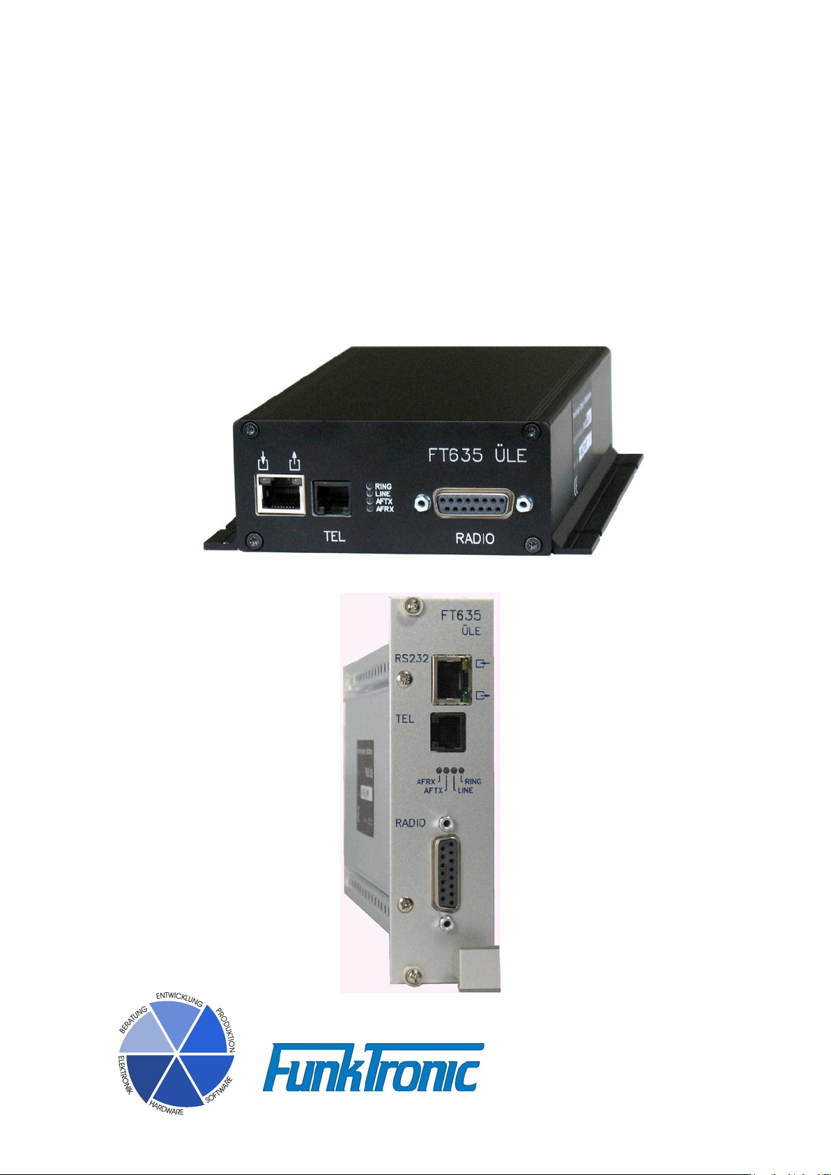
FT635 Telephone Line Interface
The FT635 telephone line interface (UELE) consists of a CPU card of Europe with an attached
TIM (telephone interface module).
There are 3 different housings available. The standard version is a flange aluminum housing. There
also is a 19“ plug-in unit and a special version in the FT635 system housing.The version in the
system housing has a connector which is pin-compatible to FT633UELE to the two-way radio.In
the standard version only the most important connectors are available as sockets on the front.
The FT635UELE serves as interface between the telephone network and the radio installation.
For phone lines with direct outward dialing the FT635 can be additionally equipped with the option
VMM (voice memory/voice response).
To connect the UELE to the radio there is a 15-pole D-Sub--connector available (the version in
the FT635 system housing has the additional 37-pole D-Sub-connector). The connection to the
telephone network is made by a RJ11 connector.
Connection possibilities
The telephone network is connected to the 6-poleTRJ11 connector (TEL) by two-wire
technology (analog a/b) and can optionally work with the DTMF- or the pulse dialing
method. Ex factory the dialing method is preset to "DTMF dialing“.
The connection to the radio is made by the 15-pole D-Sub-connector (RADIO). It includes
squelch input, PTT output, AF input, AF output, 4 digital outputs (or digital inputs) and the
power supply. The PTT output and the AF inputs/outputs are potential-free.
The 37-pole D-Sub-connector of the version in the FT635 system housing has 12 additional
digital outputs (or digital inputs), a second AF input, a second AF output, 2 analog inputs
and a RS232 interface.
The RS232 interface and 5 digital inputs (or digital outputs) can be connected at the RJ45
connector.
Reg. Function
366 4. digit
0 = pulse dialing
1 = DTMF dialing
Kompetent für Elektroniksysteme
- 3 -
ft635ule _eng(21.06.2012)
Page 4
ft635ule_eng (21.06.2012)
- 4 -
- 5 -
ft635ule _eng(21.06.2012)
Kompetent für Elektroniksysteme
Kompetent für Elektroniksysteme
FT635 UELE
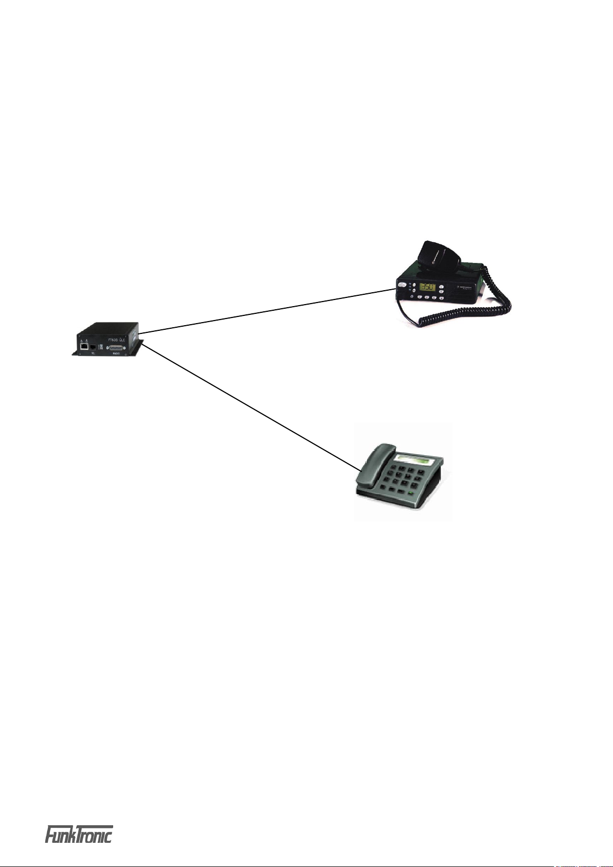
Connection examples
Automatic call forwarding from the radio to the telephone
network resp. from the telephone network to the radio
8
/
telephone line
2
/
two-way radio
telephone
There are different applications for the operation of a FT635 UELE:
- automatic call forwarding from the telephone network to the radio
- automatic call forwarding from the radio to a telephone
Page 5

Carrier detection
The FT635UELE offers different possibilities of carrier detection. The carrier input can
be low or high active and a pull-up resistance can be activated additionally. Alternative
possibilities are the AF controlled carrier and the phantom control. For phantom control
the solder jumper JP2 has to be resoldered. The carrier is active if one or both pins of the
AF input of the radio are connected to ground.
Reg. Function
056 1. digit
0 = carrier input low active, pull-up on
1 = carrier input high active, pull-up off
2 = AF controlled carrier
3 = phantom carrier
4 = carrier input low active, pull-up off
5 = carrier input high active, pull-up on
If the normal carrier input is also to be used as external input additionally or exclusively for
other functions, 2 or 3 needs to be programmed at the first digit in register 056.
Reg. Function
056 2. digit: configuration of the carrier input without
carrier function
(if the 1. digit is programmed with 2 or 3)
possible values: 0,1,4,5 same as 1.digit
Transmitter control
The FT635 Interface can activate the transmitter in 3 different ways. The PTT relay has
a potential-free output for the PTT activation. One pin has to be connected externally to
the reference voltage which is needed by the two-way radio (normally GND or +Batt) and
the other pin is connected to the PTT input of the two-way radio. Alternatively there is the
possibility of PTT phantom control. With phantom control the PTT is acitvated by switching
the center tap of the output transformer to GND. To activate the phantom control the
solder jumper JP1 needs to be resoldered. For reasons of compatibility to FT633UELE
the PTT by a switching output is possible. For FT633UELE I/O15 is used as PTT output.
Ex factory I/O15 is configurated as input for FT635UELE and needs to be reprogrammed
(see section "In- and outputs").
Kompetent für Elektroniksysteme
- 5 -
ft635ule _eng(21.06.2012)
Page 6

- 7 -
ft635ule _eng(21.06.2012)
Kompetent für Elektroniksysteme
Transmitter lead-up time
The lead-up time is defined as the time between the activation of the transmitter and the
start of the signaling (e.g. tone sequence). It can be adjusted from 0 to 990ms. Ex factory
it is set at 100ms.
Reg. Function
055 1.+ 2. digit: transmitter lead-up time nn * 10ms
Transmitter follow-up time
The follow-up time is defined as the time between the end of the signaling(e.g. tone
sequence) and the end of the transmission. It is adjustable from 0 to 990ms. Ex factory
it is set at 100ms.
Reg. Function
055 3.+ 4. digit: transmitter follow-up time nn * 10ms
Transmission time limit
The transmitter can be turned off by the transmission time limit. The transmission time limit
can be adjusted form 1 to 999s or be turned off with 000. Ex factory it is turned off.
The transmission time limit can be adjusted separately in the telephone mode and in the
none-telephone mode. Currently only the telephone mode is used with the UELE.
Reg. Function
010 1.- 3. digit: transmission time limit in none-telephone mode nnn * 1s
310 1.- 3. digit: transmission time limit in telephone mode nnn * 1s
Kompetent für Elektroniksysteme
- 6 -
ft635ule_eng (21.06.2012)
Page 7

In- and outputs
The FT635UELE has 16 in- and outputs and the carrier input, which can be used for
special functions. The 16 in- and outputs can be programmed as either input or output.
Ex factory I/O0-7 are configurated as open collector outputs and I/O8-15 as inputs with
27kOhm pullup to 5V. With an alternative equipping all 16 I/O can be fitted with pullup
resistors to +5V or to supply voltage or as open collector output.
Reg. Function
095 1.- 8. digit: I/O-configuration 1 (I/O 0-7)
096 1.- 8. digit: I/O-configuration 2 (I/O 8-15)
For all digits: 0=output, 1=input
Inputs
If the I/Os are configured as inputs then they each use 2 registers in which their
functions are programmed. In the first register the function is programmed when
activating the input (input switches to ground) and in the second register the function
is programmed when the input is deactivated (input is opened or switches to +).
Currently there are 2 possible functions:
- T11-55 input (see section T11-55)
- night mode input (see section Night mode)
Reg. Function
108 1. digit: function for input I/O 0
in case of activation to GND
109 1. digit: function for input I/O 0
in case of deactivation to +
110 - 141 the same as register 108/109 for I/O 1-15 and carrier input
possible functions at
1. digit
0: no function
3: T11-55 input
9: night mode input
further configuration for T11-55 input (1.digit = 3)
2. digit
0: channel free
1: channel busy
further configuration for night mode input (1.digit = 9)
2. digit
0: normal operation
1: night mode
Kompetent für Elektroniksysteme
- 7 -
ft635ule _eng(21.06.2012)
Page 8

- 9 -
ft635ule _eng(21.06.2012)
Kompetent für Elektroniksysteme
Outputs
If the I/Os are configured as output, then there currently there are 3 possible functions:
- additional PTT output
- output for telephone active
- digital output by tone sequence (see section Digital output control)
Up to 4 I/Os can be programmed with digital output functions.
Reg. Function
097 1. digit function 1
097 2. digit digital output for function 1
097 3.+ 4. digit digital output and function 2
097 5.+ 6. digit digital output and function 3
097 7.+ 8. digit digital output and function 4
possible functions at 1./ 3./ 5./ 7. digit:
0: no function
1: PTT output normal
2: PTT output inverted
3: TEL output normal
4: TEL output invertes
possible digital outputs at 2./ 4./ 6./ 8. digit:
0-9,A-F: I/O 0-9,10-15
Examples for function 1 = I/O15 = PTT output the same as FT633UELE:
Register 097: 1Fxxxxxx
Digital output control
The digital outputs I/O8-15 can be switched by transmitting certain 8-tone sequences from
the radios. In this process the first 5 digits of the 8-tone sequence are evaluated selectively.
The last 3 digits of the 8-tone sequence are interpreted as decimal value and are converted
into the binary switching pattern of the 8 digital outputs I/O8-15. This means that for the
last 3 digits values varying from '000' and '255' can be entered (8-bit-number). The tone
sequence for switching is acknowledged by a 5-tone sequence acknowledgement. The
acknowledgement can be turned off by 'F' at the 1. digit.
Example: The last 3 digits are '036'. The decimal number '036' corresponds to the 8bit binary number '0010 0100', so that the digital outputs can be switched as follows:
('1'=ON, '0'=OFF).
digital output 15 14 13 12 11 10 9 8 output state 0 0 1 0 0 1 0 0
Reg. Function
030 1.- 5. digit tone sequence for digital output control for I/O8-15
030 6.- 8. digit needs to be programmed with F
031 1.- 5. digit acknowledgement after digital output reswitching (Reg.030)
Kompetent für Elektroniksysteme
- 8 -
ft635ule_eng (21.06.2012)
Page 9

AF-signaling pathways
All AF pathways are switched wear-free with analog switches. The radio in-and outputs
(except discriminator input and CTCSS output) are galvanically decoupled using a
transformer.
AF-signals (telephone to radio)
The level of the incoming telephone signal is adjusted in register 620. The AF signal is
transferred from here to the the radio output by means of the output level adjustment. Also
see section Service program/adjustment.
AFsignals (radio to telephone)
The AF signals of the radio go through an input level adjustment. The discriminator input of
the UELE also has an electronic input level adjustment. Also see section Service program/
adjustment. The level of the outgoing telephone signal is adjusted in register 621.
Signalings of the radio (e.g. 5-tone sequences) which are processed in the UELE, can
optionally be connected to the normal RX output or to the discriminator output of the twoway radio. This is is programmed in the EEPROM-register 080:
Reg. Function
080 6.digit tone sequence decoder
7.digit FFSK decoder
8.digit CTCSS (subtone) decoder (optionally available)
For all 3 digits the following applies:
1 = decoder at the RX input (radio in) of the UELE
2 = decoder at the discriminator input (discriminator in) of the UELE
To program the EEPROMs please read the section Programing mode EEPROM. Ex factory
the tone sequence decoder and the FFSK decoder are connected to „radio in“ and the
CTCSS decoder is connected to „discriminator in“ .
DTMF
The FT635UELE has 2 independent DTMF decoders. Therefore a directional switchover, as with the FT633UELE, is no longer necessary. Now it is possible to wait for an
ending call from the radio and to decode new mobile IDs from the telephone. The following
assignments of the progammable values to the DTMF tones apply in all registers in which
DTMF tones are programmed:
programmed values: 0,1,2,3,4,5,6,7,8,9,A,B,C,D,E,F
DTMF tone: 0,1,2,3,4,5,6,7,8,9,A,B,C,D,*,#
For both directions the DTMF signals have a delete key and an end key . These keys can
be configured individually. Ex factory '*' is the delete key and '#' is the end key. By using
the delete key the complete telephone number is deleted and the entry begins anew. By
using the end key the input is finished and the call is started. It is necessary to use the
end key when dialing via DTMF from the radio.
- 9 -
Kompetent für Elektroniksysteme
ft635ule _eng(21.06.2012)
Page 10
- 11 -
ft635ule _eng(21.06.2012)
Kompetent für Elektroniksysteme
Calling the mobile ID via telephone is started with the end key or automatically after the
complete input of the mobile ID.
Ex factory telephone dialing uses DTMF, but pulse dialing is also possible.
Specifications for the DTMF encoder and decoder can be adjusted in the TIM, if problems
arise.
Reg. Function
357 1. digit delete key from radio
357 2. digit end key from radio
357 3. digit delete key from telephone
357 4. digit end key from telephone
366 4. digit dialing mode
0 = pulse dialing, 1 = DTMF dialing
Tone sequence encoder and decoder
The FT635UELE can decode tone sequences from the radio by means of the normal AF
input or the discriminator input. Ex factory the tone sequences are decoded at the normal
AF input. The standard version does not include the discriminator input. The tone sequence
encoder always transmits via the normal AF output to the radio. The tone sequence for
encoder and decoder can only be adjusted together. But the length of the individual tones
can be adjusted separately. After changing the tone sequence the duration of the tones
also has to be reprogrammed. This is not automatically carried out by the FT635UELE.
The tone sequence encoder supports the following ID-Modes when calling a vehicle.
ID-Mode Function
0 5-tone sequence
1 double tone sequence call, link tone, ID 2*X-tone sequence (number of
tones of register 081 / 6. digit)
2 double tone sequence, ID, link tone, call 2*X-tone sequence (number of
tones of register 081 / 6. digit)
3 6-tone sequence (5-tone sequence with attached 1 digit ID of register 015 /
5.digit)
4 7-tone sequence (5-tone sequence with attached 2 digit ID of register 015 /
4.+5.digit)
5 8-tone sequence (5-tone sequence with attached 3 digit ID of register 015 /
3.-5.digit)
8 4-tone sequence
9 X-tone sequence (number of tones of register 081 / 6.digit)
F no tone sequence
The decoder evaluates each incoming tone sequence individually. There are 10 decoders
(T1-T10) with corresponding configuration register available for the telephone functions.
The decoder T1 has the highest priority and the decoder T10 the lowest.
Kompetent für Elektroniksysteme
- 10 -
ft635ule_eng (21.06.2012)
Page 11

Incoming tone sequences are checked for conformity with the decoders T1-T10. If there
is a match, this decoder is processed and all the following decoders with lower priority
are not checked anymore. The correct number of tones and conformity with the key
tones is necessary for decoding. If all tones are to be accepted at a certain position of
the tone sequence or if this position does not exist in the tone sequence (e.g. tones 6-8
when decoding a 5-tone sequence), then the decoder must be programmed with 'F' at
this digit.
Example:
decoder T3 is to decode all 6-tone sequences which begin with 1234 (123400-123499)
register 322 = 1234FFFF: decodes all tone sequences which begin with 1234, tone
duration 4-15 digits
register 332 = 6xxxxxxx: 1.digit: 6 = valid tone duration is 6-tone sequence
Reg. Function
015 1.- 8. digit: own ID when transmitting ID
055 1.+ 2. digit: nn * 10ms PTT advance time before tone sequences and tones
055 3.+ 4. digit: nn * 10ms PTT follow-up time after tone sequences and tones
080 1.- 3. digit: decoder: maximum tone duration 1. tone nnn * 5ms
080 4.+ 5.digit: decoder: minimum tone duration of all tones nnn * 5ms
080 6. digit: tone sequence decoder at: 1=radio AF, 2=discriminator
081 1.- 3. digit: decoder: maximum tone duration all other tones nnn * 5ms
081 4. digit: decoder locking period after transmitting tone sequences n * 100ms
081 5 . digit: tone sequence encoder and decoder (0/1/2/3:ZVEI1/CCIR/ZVEI2/EEA)
081 6. digit: number of tones for ID-Mode 1,2,9 (RK,KR,R) (3-7)
082 1.+ 2. digit: encoder: tone duration 1. Ton nn * 10ms
082 3. digit: encoder: tone duration all other tones n * 10ms
082 4.+ 5. digit: pause time between call and identification nn * 10ms
320 - 329 key tones for decoder T1 to T10
330 - 339 configuration for decoder T1 to T10
33x 1. digit: number of tones
33x 2. digit: type of decoder:
0: decoder off
1: starting call
2: short dial
3: direct dialing
4: night mode
9: ending call
further configuration for starting call (2. digit = 1):
3. digit:
0: starting call only, no function during call
1: also ending call during a call in progress
4. digit: transmit confirmation tone y/n (1/0)
(must not be activated for block dialing)
further configuration for short dial (2. digit = 2):
3. digit: position in tone sequence for "100" range short dial number (0=default)
- 11 -
Kompetent für Elektroniksysteme
ft635ule _eng(21.06.2012)
Page 12

- 13 -
ft635ule _eng(21.06.2012)
Kompetent für Elektroniksysteme
4. digit: position in tone sequence for "10" range short dial number (0=default)
5. digit: position in tone sequence for "1" range short dial number (0=default)
6. digit: "100" range short dial number default
7. digit: "10" range short dial number default
8. digit: "1" range short dial number default
At the 3.-5. digit the digit in the tone sequence is programmed whose value is used as the
short dial number. If 0 is programmed, then the value which is programmed at the 6.-8.
digit will be used.
Example: received tone sequence 987654, register 33x=62045100 = dialed short dial
number 165
3. digit 0: "100" range short dial number is derived from 6. digit in register (1)
4. digit 4: "10" range short dial number is derived from 4. digit of the tone
sequence (6)
5. digit 5: "1" range short dial number is derived from 5. digit of the tone
sequence (5)
further configuration for direct dialing (2. digit = 3):
3. digit: position in the tone sequence, with the 1. direct dialing number
4. digit: lowest permitted value for the 1. direct dialing number
5. digit: highest permitted value for the 1. direct dialing number
6. digit: number of prefix numbers to telephone (0-2)
7.- 8. digit: prefix numbers 1 and 2
At the 3.digit the digit in the tone sequence is programmed which contains the 1. direct
dialing number. The range for a valid 1. direct dialing number can be limited at the 4. and
5. digit. All following numbers of the tone sequence are dialed. If in addition one or two
specified prefix numbers are to be dialed before the direct dialing numbers, this can be
programmed at the 6.digit. These numbers are programmed at the 7. and 8. digit.
Example: received tone sequence 987654, register 33x=63427120 = dialed call number
2654
3. digit 4: 1. direct dialing number is at the 4. digit of the tone sequence (6)
4. digit 2: min. value of the 1. direct dialing number
5. digit 7: max. value of the 1. direct dialing number (valid range 2-7)
6. digit 1: a prefix number of the 7. digit in register (2)
7. digit 2: 1. prefix number (2)
further configuration for night mode (2. digit = 4):
3. digit: 0=off, 1=on, 2=corresponding to 4.-7.digit, 3=on/off toggling
4. digit: digit in the tone sequence for night mode configuration
5. digit: value for turning on the night mode
6. digit: value for turning off the night mode
7. digit: value for toggling of the night mode
At the 3. digit the new status of the night mode is programmed. The turning on or off of the
night mode can be determined or it can be switched back and forth between the two kinds
of status. Alternatively a digit in the tone sequence can also determine the new status.
Example: received tone sequence 98760 for off, 98761 for on, register 33x=542510F0
3. digit 2: new status is stated in the tone sequence
4. digit 5: new status is stated at the 5. digit of the tone sequence
5. digit 1: xxxx1 (98761)for activating night mode
6. digit 0: xxxx0 (98760) for deactivating night mode
7. digit F: xxxxF (9876F) no toggling allowed (9876F does not exist)
Kompetent für Elektroniksysteme
- 12 -
ft635ule_eng (21.06.2012)
Page 13

Dial-up - telephone -> radio
Reg. Function
360 4. digit: T11-55 for dial-up telephone to radio y/n (1/0)
367 5. digit: number of ring tones until line seizure
Automatic connection - telephone -> radio
An incoming telephone call effects the automatic line seizure after the N-th ring tone. Two
signal tones at intervals of 1s are transmitted to the telephone. After that the connection to
the radio is connected through. If the function T11-55 is activated, then the 2. signal tone
will be delayed until the channel is free. If the channel is busy for longer than 45 seconds
the connection will be terminated. For information on the function of T11-55 please read
section T11-55. The phone call is ended automatically by modulation monitoring and time
monitoring or manually by an ending call.
Reg. Function
363 1. digit: F=immediate automatic connection
Direct dialing by DTMF - telephone -> radio
An incoming telephone call effects the automatic line seizure after the N-th ring tone and a
signal tone is transmitted to the telephone. 0 to 7 numbers are preselected in the EEPROMRegister 361 and the missing numbers (coded with "F" in the EEPROM) are completed
by DTMF numbers. The call input always takes place until all 7 digits have either been
preselected or entered. If e.g. a 5-tone sequence is to be transmitted then the 6. and 7.
digits must not be programmed with 'F'.Otherwise additional (unused) DTMF numbers
must be entered. After complete call input the call is either started with the end key on
the telephone (normally the #-key) or automatically. If not all numbers have been entered
when the end key is pressed, then the telephone subscriber receives an error message
(2 short signal tones). If the function T11-55 is activated, then the call transmission will
be delayed until the channel is free. But if the channel is busy for more than 45 seconds
the connection set-up is terminated. For information on the function of T11-55 please
read section T11-55. After transmitting the call a second signal tone is transmitted to the
telephone and the connection will be set up. If a wrong number is entered the complete
number can be deleted with the delete key on the telephone (normally the *-key). Then
the input begins anew.
Within 15s after sending a call the last call can be sent again by using the end key. Also
several radio participants can be called (consecutive dialing), to do this delete the last
entry with the delete key during the call and begin a new entry.
5s after the entry of the last DTMF number the input mode is automatically terminated. If
no call has been transmitted to the radio before, then the connection will be ternimated.
The call is automatically terminated by modulation monitoring and time monitoring or
manually by an ending call.
- 13 -
Kompetent für Elektroniksysteme
ft635ule _eng(21.06.2012)
Page 14

- 15 -
ft635ule _eng(21.06.2012)
Kompetent für Elektroniksysteme
Reg. Function
361 1.-7. digit: preset digits for tone sequence for direct dialing Tel>Radio
361 8. digit: begin call with end key y/n (1/0)
363 1. digit: ID-mode of the tone sequence for direct dialing Tel>Radio
363 2. digit: link tone for double tone sequence
Automatic call forwarding with direct call - tel -> radio
The automatic transfer is a special case of direct dialing by DTMF if all digits of the tone
sequence are preprogrammed. An incoming phone call effects the automatic line seizure
after the N-th ring tone, a signal tone is transmitted to the telephone and the programmed
call is transmitted to the radio. If the function T11-55 is activated then the call will be
delayed until the channel is free. But if the channel is busy for longer than 45 seconds,
then the connection wiil be terminated.. For information on the function of T11-55 please
read section T11-55. After transmission of the call a second signal tone is transmitted to
the telephone and the connection is set up.
The phone call is automatically terminated by modulation monitoring and time monitoring
or manually by an ending call.
Night mode - telephone -> radio
Night mode is an alternative possibility to make a connection from phone to two-wayradio. As in normal operation all 3 possibilites for making a connection are possible
(automatic connection, direct dialing with DTMF and automatic transfer with direct call).
The only difference between night mode and normal operation is the use of different
registers.Switching from normal operation to night mode is done by a tone sequence from
the radio or by a switching input.
Reg. Function
362 1.-7. digit: night mode:preset digits for tone sequence when direct dialingTel>Radio
362 8. digit: night mode active y/n (1/0)
363 3. digit: night mode: ID-mode of the tone sequence when direct dialing Tel>Radio
363 4. digit: night mode: link tone for double tone sequence
Radio -> telephone
Reg. Function
320-339 tone sequence decoder and corresponding configuration
360 1.-3. digit: T11-55 at connection setup two-way radio to telephone y/n (1/0)
360 1. digit: on starting call + dialing with DTMF
360 2. digit: on speed dial
360 3. digit: on direct dialing with DTMF
Direct dialing with DTMF - radio -> telephone
For direct dialing with DTMF any telephone number can be dialed. The radio user can
initiate the direct dialing procedure (radio --> telephone) by two different kinds of starting
calls: either by transmitting a tone sequence or by transmitting a sequence of DTMF-tones.
The pause between 2 DTMF-tones must not be longer than 5 seconds.
Both starting call variants can be used alternatively or together. The UELE will acknowledge
the starting call with a key tone if programmed. After the starting call the DTMF-dial tones
which include the telephone number must follow. For this the first DTMF-dial tone has to
- 14 -
Kompetent für Elektroniksysteme
ft635ule_eng (21.06.2012)
Page 15

to be received not later than after 15 seconds and each further tone not later than after 5
seconds. All DTMF-tones received from the radio user are buffered so that fast incoming
DTMF-tones can be processed. After entering the telephone number completely the dialing
process is started by pressing the END key (normally the #-key). If the function T11-55 is
activated the start of the dialing will be delayed until the channel is free. But if the channel
is busy for more than 45 seconds the connection setup will be terminated. For information
on the function of T11-55 please read section T11-55. Before the start of the dialing a key
tone (acknowledging tone) is transmitted to the radio user (see section Signal tone delay).
The line will be seized and depending on the configuration it will be checked if there is a
dial tone (see section Call tone detection).
Then the telephone number which has been entered will automatically be dialed in the
desired dialing method. If a wrong number is entered the complete number can be deleted
by using the delete key (normally the *-key) and the entry begins anew. The phone call is
automatically terminated by modulation monitoring and time monitoring or manually by
an ending call.
Hint: The signal tone after decoding the starting call must not be activated, if the dialing
is to be done by block dialing. When block dialing, the starting call and the DTMF-tones
of the telephone number are transmitted by the two-way radio as a block without longer
pauses.
Reg. Function
357 5. digit: transmit confirmation tone after DTMF starting call y/n (1/0)
358 1. digit: number of digits in the DTMF starting call (0-7)
358 2.-7. digit: code for starting call by DTMF
Direct dialing with tone sequence - radio -> telephone
When dialing directly with tone sequence telephone numbers with a defined length are
dialed. The length of the telephone number is limited by the maximum length of the tone
sequence of 15 digits minus the fixed digits and plus the prefix numbers. Additionally a
range for the first dial number can be defined. The incoming tone sequence must have
the length which has been programmed in the configuration register and must correspond
with the key tones in the decoding register. Also the 1. dial number must be within the
programmed range. If the function T11-55 is activated then the start of the dialing will be
delayed until the channel is free. But if the channel is busy for more than 45 seconds the
connection setup will be terminated. For information on the function of T11-55 please read
section T11-55.
Before the start of the dialing a signal tone (acknowledging tone) is transmitted to the
radio user (see section Signal tone delay). The line will be seized and depending on the
configuration it will be checked if there is a dial tone (see section Call tone detection). Then
the telephone number which has been entered will automatically be dialed in the desired
dialing method. The telephone number consists of the programmed prefix numbers and
then all numbers of the tone sequence of the programmed 1. direct dialing number. The
phone call is automatically terminated by modulation monitoring and time monitoring or
manually by an ending call.
Speed dial - radio -> telephone
The FT635UELE has a speed dial memory of 1000 entries with 16 digits each. For speed
dialing a 3-digit speed dial number has to be generated from the tone sequence. The
content of this speed dial memory will then be dialed. The speed dial number can either
- 15 -
Kompetent für Elektroniksysteme
ft635ule _eng(21.06.2012)
Page 16

- 17 -
ft635ule _eng(21.06.2012)
Kompetent für Elektroniksysteme
be completely comprised in the tone sequence or it is composed of variable digits in the
tone sequence and fixed digits in the register. After the tone sequence has been identified
correctly the line is seized and according to the configuration it will be checked if there is
a call tone (see section Call tone detection). Then a signal tone is transmitted to the radio
subscriber (see section Signal tone delay) and the number saved in the speed dial memory
is automatically dialed in the desired dial mode.
The call is automatically terminated by modulation monitoring and time monitoring or
manually by an ending call.
Speed dial memory
The speed dial memory has 1000 entries with a length of 16 digits each. It is read and
programmed by the RS232 interface. The reading can be done either separately or as a
block. Also the output can be done as plaintext or as a list for editing and uploading. With
the help of a terminal program the outputs of the FT635UELE can be saved as a text file
and can be processed later. When uploading the speed dialing list the terminal program
has to wait 10ms after each line before the next line can be transmitted.
The speed dial memory can contain all characters for formating the telephone number.
They are simply ignored when dialing. The numbers 0-9 are used as dial numbers and P
as 1s dial pause. For DTMF-dial the DTMF-tones A-F are also allowed.
Speed dial functions:
WRxxx-yyy...display speed dial memory xxx (-yyy) (in plaintext)
WLxxx-yyy...display speed dial memory xxx (-yyy) (as a list for uploading)
WPxxx:yyyy...y..prog. speed dial memory xxx with y (max. 16 digits)
WCxxx-yyy....delete speed dial memory xxx-yyy
Call monitoring
Maximum duration of a call
All connections are terminated after N seconds at the latest, if they have not been
terminated before. At the beginning of the last 30 seconds an alarm tone is transmitted to
the telephone subscriber. The maixmum duration of a call is adjustable from 1 to 9999s
or can be turned off with 0. Ex factory it is set at 5 minutes (300s).
Reg. Function
365 1.- 4. digit: maximum duration of call nnnn * 1s
Maximum transmission time for Simplex
If the maximum transmission time is exceeded, for example by loud noises in the telephone
line, the telephone call will be terminated automatically. It is adjustable from 1 to 990s or
can be turned off with 0. Ex factory it is set at 45s.
Reg. Function
366 1.- 3. digit: maximum transmission time for Simplex nnn * 1s
Maximum receiving time for Simplex
If the maximum receiving time is exceeded, for example by a constantly active carrier the
telephone call will be terminated automatically. It is adjustable from 1 to 990s or can be
turned off with 0. Ex factory it is set at 45s.
Kompetent für Elektroniksysteme
- 16 -
ft635ule_eng (21.06.2012)
Page 17

Reg. Function
367 1.- 3. digit: maximum receiving time for Simplex nnn * 1s
Modulation monitoring
The connection is disconnected after N seconds without speech modulation and the line
is free. The maximum duration of a call without speech modulation is adjustable from 1
to 99s or can be turned off with 0.
Ex factory it is set at 10s.
Reg. Function
365 5.- 6. digit: maximum length of call without modulation nn * 1s
Disconnection by ending call
The radio user can disconnect an existing telephone connection with two different kinds
of ending calls:
either by transmitting a tone sequence which has been configured as ending tone in one of
the telephone decoders T1-T10 or by transmitting a sequence of 7 DTMF-tones maximum
which have been programmed as ending call.
The pause between 2 DTMF- ton es must not exc eed 5 se conds.
Both ending call variants can be used together or alternatively.
Reg. Function
320-339 tone sequence decoder and corresponding configuration
359 1. digit: number of digits in the DTMF ending call (0-7)
359 2.-7. digit: code for ending call by DTMF
Signal tone delay
With all variants of connection setup (radio ==> telephone) a signal tone (acknowledging
tone) is transmitted to the radio subscriber. If the radio subscriber is not ready to receive
immediately after transmission of the signaling which releases dialing (tone sequence
resp.DTMF-tone) , maybe the signal tone cannot be received. In this case a signal tone
delay in steps of 100ms can be programmed.
Reg. Function
369 2. digit: signal tone delay to radio n * 100ms
Operating mode
The FT635UELE supports 3 operating modes for transmitter control(Simplex (Vox),
Duplex and Simplex (carrier)).
With Simplex (Vox) speech is decoded by telephone and radio. If one direction is activated
it will stay active as long as there is speech. Only afterwards the other direction can be
activated.
The delay times and levels for Vox are preset, but can be adjusted in the TIM.
With Simplex (carrier) the radio does not decode speech but the carrier input. The
following procedure is the same as with Simplex (Vox). With Simplex maximum times for
continuous transmitting and receiving can be set. If these times are exceeded the call will
be terminated.
With Duplex the transmitter stays busy till the end of the connection. In both Simplex
operation modes the transmitter is activated by speech control from the telephone. A certain
amount of time is needed to recognize speech and activate the transmitter. Because of
this,,a part of the first word is lost. To avoid this the UELE can delay speech from telephone
to radio. If a longer delay time is needed the speech can be compressed during the delay.
Kompetent für Elektroniksysteme
- 17 -
ft635ule _eng(21.06.2012)
Page 18

- 19 -
ft635ule _eng(21.06.2012)
Kompetent für Elektroniksysteme
There are two different ways of compressing speech. The A-Law compression halves the
resolution from 16 Bit to 8 Bit and half the Baud rate reduces the sampling rate from 28,8kHz
to 14,4kHz. For especially long delays both compression methods can be combined. Ex
factory the operation mode "Simplex (Vox)" and no delay is set.
Reg. Function
366 1.- 3. digit: max. transmitting time for Simplex nnn * 1s
366 5. digit: operation mode 0=Simplex (VOX), 1=Duplex, 2=Simplex (carrier)
367 1.- 3. digit: max. receiving time for Simplex nnn * 1s
617 1.- 3. digit: speech delay telephone > radio nnn * 1ms
617 4. digit: compression: 0 = none (max. 55ms delay time)
1 = A-law (max. 110ms delay time)
2 = half the Baud rate (max. 110ms delay time)
3 = A-law and half the Baud rate (max. 220ms delay time)
Voice announcement (option)
When connecting to the telephone network the then required voice announcements to the
telephone subscriber can be switched if the FT635UELE is additionally equipped with the
option VMM.
Recording of texts
The recording is controlled by the RS232 and can be made by radio or telephone. Enter
the text number and the recording source in the monitor command. If you want to record
the texts from the telephone, the telephone connection must be set up beforehand. Then
you start and end the recording with the blank key on the terminal.
The maximum number of texts is 240 and is also limited by the total memory capacity
of 4 minutes (240 seconds). The UELE only uses the texts 1 and 2. Ex factory both
announcements have been recorded with the following texts:
Text 1 (with setup telephone --> radio):
„Please wait - the desired subscriber has been called via the public radio network
(text is in German)
Text 2 (with setup radio --> telephone):
„You are now connected to the subscriber via the public radio network!“(text in German)
When connecting between radio network and telephone network both texts no 1 and no
2 can be switched to the telephone subscriber as voice announcements.
Reg. Function
369 3. digit: voice announcement (text 1) with connection setup telephone --> radio
369 4. digit: voice announcement (text 2) with connection setup radio --> telephone
For both digits the following applies:
0 = no voice announcement
1 = during voice announcement no AF audible from the radio
2 = during voice announcement AF from the radio additionally audible
Kompetent für Elektroniksysteme
- 18 -
ft635ule_eng (21.06.2012)
Page 19

Example for the configuration
1. 5-Tone sequence system with mixed vehicle- and telephone numbers and
dialing from the speed dial memory
- mobile call ID 12100-12149, two digit input
- telephone numbers 12150-12199, speed dialing register 050-099
- register 320 = 121FFFFF: decodes all tone sequences which begin with 121
- register 330 = 52045000: 1. digit: 5-tone sequence is decoded
2. digit: speed dialing
3. digit: "100" range speed dialing number is fixed and at the 6.digit
4. digit:"10" range speed dialing is at the 4. digit of the tone sequence
5. digit: "1" range speed dialing is at the 5. digit of the tone sequence
6. digit: "100" range speed dialing = 0
7.+8. digit: unused as the digits come from the tone sequence
- speed dial memory 000-049: must be empty (mobile call ID)
- speed dial memory 050-099: contains the telephone numbers
2. 8-Tone sequence system for telephone numbers and three digit dial from the
speed dial memory
- telephone numbers 12345000-12345999, speed dialing register 000-999
- register 320 = 12345FFF: decodes all tone sequences which begin with 12345
- register 330 = 82678000: 1. digit: 8-tone sequence is decoded
2. digit: speed dialing
3. digit: "100" range speed dialing number is at the 6. digit of the tone
sequence
4. digit: "10" range speed dialing is at the 7. digit of the tone sequence
5. digit: "1" range speed dialing is at the 8. digit of the tone sequence
6.-8. digit: unused as the digits come from the tone sequence
- speed dial memory 000-999: contains the telephone numbers
3. 5-Tone sequence system with mixed mobile call ID and telephone numbers,
direct dialing with tone sequence and DTMF
- mobile call ID 12100-12109 and 12130-12198, two digit input
- telephone numbers 12110-12129, extensions 510-529
- free dialing of the telephone number with 12199 and DTMF consecutive dialing
- register 320 = 12199FFF: decodes all tone sequences which begin with 12199
- register 330 = 51010000: 1. digit: 5-tone sequence is decoded
2. digit: starting call
3. digit : no ending call with 12199
4. digit: transmit confirmation tone to radio
- register 321 = 121FFFFF: decodes all tone sequences which begin with 121
- register 331 = 53412150: 1. digit: 5-tone sequence is decoded
2. digit: direct dialing
3. digit: 4. digit of the tone sequence is 1. dial number
4. digit: the 1. dial number must be 1 or higher
5. digit: the 1. dial number must be 2 or lower
6. digit: a prefix number
7. digit: first dial 5
8. digit: unused as only one prefix number is used
Notice: As only the highest decoder with matching number of tones and key tones is
processed, the starting call must be programmed before direct dialing. If they were
Kompetent für Elektroniksysteme
- 19 -
ft635ule _eng(21.06.2012)
Page 20

- 21 -
ft635ule _eng(21.06.2012)
Kompetent für Elektroniksysteme
programmed vice versa, then the starting call 12199 would be decoded as direct dialing
tone sequence and would be discarded, because it does not fulfill the condition for the
1. dialing number. A further comparison with the lower decoders 2-10 will not take place
after that.
Call progress tone detection
Call progress tone detection is of special importance when setting up the connection
automatically. Which call progress tones the UELE detects and for what purpose is
described below.
Dial tone detection before dialing
Dial tone detection before dialing effects the whole dialing process to begin only after
detection of the dial tone when there is an automatic connection setup. The waiting period
for the dial tone is 18 seconds, after that the connection setup is terminated. If using
extension systems this function has to be turned off. In this case the dialing process begins
automatically 3-4 seconds after the line is seized according to the selected dialing process
(MFV or IWV). Ex factory call tone detection is turned off. Call tone detection is only active,
when no prefix number for an external line has been programmed.
Dial tone detection after connecting to an external line
If, when setting up a connection automatically, an external line is needed (only possible
for extensions with which external calls can be made) the prefix number for an external
line (numbers 0...9) has to precede the telephone number (for direct dialing and speed
dialing). Dial tone detection after connecting to an external line has the effect that a dialing
process beginning with the prefix number for an external line is only continued after the
dial tone has been detected.
Ex factory dial tone detection is turned off.
Reg. Function
367 4. digit: dial tone detection on/off (1/0)
369 1. digit: prefix number for connecting to an external line (0-9, F=no connection to
an external line)
Busy tone detection
If a busy tone is detected an existing radio-telephone connection will be terminated. This
ensures that the call is terminated when the telephone user replaces the handset. If
Simplex operation was used the busy tone would activate the transmitter until time-out
. In the section Configuration table for call progress tones there are several busy tones
mentioned which have already been programmed ex factory. Customized busy tone types
can easily be added to this table.
Dial tone detection
After automatic dialing the dial tone is transmitted to the wireless network, if the dialed
telephone connection is free (for more information on the tone/pause ratio of the free line
signal also see section Configuration table for call progress tones). If the callee does not
answer the call, the transmitter is almost continuously activated by the dial tone when
Simplex is used. This makes it almost impossible to transmit an ending call. To avoid keeping
the transmitter activated until time-out, a certain period of time can be preselected during
which the callee must have answered the call. If this period is exceeded, the connection
will be terminated. It is adjustable from 1 to 999s or can be turned off with 0.
Ex factory it is set at 45s.
Kompetent für Elektroniksysteme
- 20 -
ft635ule_eng (21.06.2012)
Page 21

Reg. Function
368 1.- 3. digit: maximum duration of dial tone nnn * 1s
Configuration table for call progress tones
There is a configuration table for call progress tone detection in the EEPROM. In this table
you can define which tone/pause ratio will be detected as dial tone or busy tone.
Ex factory this table has already been programmed with two possible dial tones and with four
possible busy tones. In rare cases with some PABXs (Private Automatic Branch Exchanges)
or with certain AF noises on the telephone line there can be problems with call progress
tone detection. These usually can be solved by reprogramming or complementing this
configuration table. The table consists of maximally 19 entries (registers), each of which
shows a tone/pause ratio. By combining several entries complex call progress tones can
be decoded which consist of a combination of different tone/pause ratios.In this way it is
also possible to program the detecting of tones only after they have been decoded several
times in sequence.
If new call progress tones are to be programmed the exact periods of time of the new call
progress tones must be known. To facilitate this the UELE can output the current times.
Ex factory the following tones have been programmed:
dial tone: - 1s tone / 4s pause
- 1s tone / 5s pause
busy signal: - 400ms tone / 400ms pause / 400ms tone / 400ms pause
- 500ms tone / 500ms pause / 500ms tone / 500ms pause
- 240ms tone / 240ms pause / 240ms tone / 240ms pause
- 160ms tone / 480ms pause / 160ms tone / 480ms pause
Reg. Function
380 1. digit : exchange tone decoder n * 3,125%
380 2.- 4. digit: tone duration for continuous tone decoding nnn * 10ms
380 5.- 7. digit pause duration for pause decoding nnn * 10ms
380 8. digit: indicate decoded exchange tone times y/n (1/0)
381 - 399:
1. digit: type of exchange tone:
0=continued line
1=dial tone
2=busy tone, F=free
2.- 4. digit: tone duration nnn * 10ms
5.- 7. digit: pause duration nnn * 10ms
As examples the ex factory preset tones are described here:
Register Content - Meaning Tone duration Pause duration
381 11004000 dial tone 1s 4s
382 11005000 dial tone 1s 5s
383 20400400 busy tone 400ms 400ms
384 00400400 continuation 400ms 400ms
385 20500500 busy tone 500ms 500ms
386 00500500 continuation 500ms 500ms
387 20240240 busy tone 240ms 240ms
388 00240240 continuation 240ms 240ms
389 20160480 busy tone 160ms 480ms
Kompetent für Elektroniksysteme
- 21 -
ft635ule _eng(21.06.2012)
Page 22

- 23 -
ft635ule _eng(21.06.2012)
Kompetent für Elektroniksysteme
390 00160480 continuation 160ms 480ms
391-399 FFFFFFFF empty entries
T11-55
T11-55 prevents the start of a new call on an already busy radio channel. An additional
receiver is necessary for Duplex or Semi-Duplex operation, which monitors the transmitting
channel. Carrier detection on the transmitting channel has to be read via an input. The
normal carrier input can be used for Simplex operation. For Duplex or Semi-Duplex
operation a different input has to be used when the normal carrier input is needed (see
section In and outputs). If T11-55 is active then UELE will delay the beginning of the call
when the transmitting channel is busy until the channel is free. After maximum 45s hold
time the call will be terminated. The function can be activated separately for all varieties
of call setup.
Reg. function
360 1. digit: T11-55 for radio>tel: starting call + dialing with DTMF y/n (1/0)
360 2. digit: T11-55 for radio>tel: speed dialing y/n (1/0)
360 3. digit: T11-55 for radio>tel: direct dialing with tone sequence y/n (1/0)
360 4. digit: T11-55 for tel>radio: direct dialing with DTMF y/n (1/0)
Kompetent für Elektroniksysteme
- 22 -
ft635ule_eng (21.06.2012)
Page 23

EEPROM register layout
010 00000000 transmission time limit without telephone call
1.-3. digit nnn * 1s transmission time limit
015 12100FFF own identification when transmitting identification
030 EEEEEFFF switching output control with 8-tone sequence
(5 defined + 3 bit pattern 000-255 for IO 8-15)
031 FFFFFFFF acknowledgement for decoder reg.030
055 10100000 transmitter activation for tone sequence
1.+2. digit nn * 10ms transmitter advance time
3.+4. digit nn * 10ms transmitter delay time
056 00300000 carrier configuration
1. digit carrier mode
0:low active, pullup on
1:high active, pullup off
2:AF carrier
3:phantom
4:low active, pullup off
5:high active, pullup on
2. digit configuration for carrier input for
AF- or phantom carrier
(1. digit = 2 or 3)
0:low active, pullup on
1:high active, pullup off
4:low active, pullup off
5:high active, pullup on
3.+4. digit nn * 10ms follow-up time AF-carrier
059 11110100 activation of the RS232 outputs always / when
monitor active / never (2/1/0)
1. digit TX
2. digit SQL
3. digit DTMF
4. digit tone sequence
5. digit TIM
6. digit telephone functions
080 01810112 reference values for decoding
1.-3. digit maximum tone duration 1. tone
nnn * 5ms
4.+5. digit minimum tone duration of all tones
nn * 5ms
6. digit tone sequence decoder at:
1=radio, 2=discriminator
7. digit FFSK decoder at:
1=radio, 2=discriminator
8. digit CTCSS decoder (CTCSS is only an option) at:
1=radio, 2=discriminator
Kompetent für Elektroniksysteme
- 23 -
ft635ule _eng(21.06.2012)
Page 24

- 25 -
ft635ule _eng(21.06.2012)
Kompetent für Elektroniksysteme
081 01810500 reference values for decoding
1.-3. digit maximum tone duration remaining tones
nnn * 5ms
4. digit decoder blocking time after
transmitting tone sequence n * 100ms
5. digit tone series encoder and decoder
(ZVEI1 / CCIR / ZVEI2 / EEA/ZVEI3)
6. digit number of tones for ID-Mode 1,2,9
(RK,KR,R) (3-7)
082 07707000 configuration for encoder
1.+2. digit tone duration 1.tone nn * 10ms
3. digit tone duration remaining tones n * 10ms
(0-9,A-F = 0-9,10-15)
4.+5. digit pause time between call and identification *10ms
095 00000000 I/O-configuration 1
(I/O 0-7) 0=output, 1=input
096 11111111 I/O-configuration 2
(I/O 8-15) 0=output, 1=input
097 switching function
1. digit switching function 1
2. digit switching output for switching function 1
3.+4. digit switching output and switching function 2
5.+6. digit switching output and switching function 3
7.+8. digit switching output and switching function 4
possible functions at 1./ 3./ 5./ 7. digit:
0: no function
1: PTT output normal
2: PTT output inverted
3: TEL output normal
4: TEL output inverted
possible switching outputs at 2./ 4./ 6./ 8. digit:
0-9,A-F: I/O 0-9,10-15
108 00000000 function input 0 passive>active
109 00000000 function input 0 active>passive
110 00000000 function input 1 passive>active
111 00000000 function input 1 active>passive
112 00000000 function input 2 passive>active
113 00000000 function input 2 active>passive
114 00000000 function input 3 passive>active
115 00000000 function input 3 active>passive
116 00000000 function input 4 passive>active
117 00000000 function input 4 active>passive
118 00000000 function input 5 passive>active
119 00000000 function input 5 active>passive
120 00000000 function input 6 passive>active
121 00000000 function input 6 active>passive
122 00000000 function input 7 passive>active
123 00000000 function input 7 active>passive
Kompetent für Elektroniksysteme
- 24 -
ft635ule_eng (21.06.2012)
Page 25

124 00000000 function input 8 passive>active
125 00000000 function input 8 active>passive
126 00000000 function input 9 passive>active
127 00000000 function input 9 active>passive
128 00000000 function input 10 passive>active
129 00000000 function input 10 active>passive
130 00000000 function input 11 passive>active
131 00000000 function input 11 active>passive
132 00000000 function input 12 passive>active
133 00000000 function input 12 active>passive
134 00000000 function input 13 passive>active
135 00000000 function input 13 active>passive
136 00000000 function input 14 passive>active
137 00000000 function input 14 active>passive
138 00000000 function input 15 passive>active
139 00000000 function input 15 active>passive
140 00000000 function input SQL passive>active
141 00000000 function input SQL active>passive
108-141 1. digit = function type
0: no function
3: T11-55 input
9: night mode input
function 3: T11-55 input
2. digit: active/passive (1/0)
function 9: night mode input
2. digit: on/off (1/0)
310 00000000 transmitting time limit during a telephone call
1.-3. digit = nnn * 1s transmitting time limit in telephone mode
320 12399FFF telephone decoder 1
321 123FFFFF telephone decoder 2
322 88FFFFFF telephone decoder 3
323 EEEEEFFF telephone decoder 4
324 EEEEEFFF telephone decoder 5
325 EEEEEFFF telephone decoder 6
326 EEEEEFFF telephone decoder 7
327 EEEEEFFF telephone decoder 8
328 EEEEEFFF telephone decoder 9
329 EEEEEFFF telephone decoder 10
320-329 1.-8. digit = tone sequence to be decoded
program unused and variable digits with 'F'
330 51110000 configuration for telephone decoder 1
331 52045000 configuration for telephone decoder 2
332 53309000 configuration for telephone decoder 3
333 00000000 configuration for telephone decoder 4
- 25 -
Kompetent für Elektroniksysteme
ft635ule _eng(21.06.2012)
Page 26

- 27 -
ft635ule _eng(21.06.2012)
Kompetent für Elektroniksysteme
334 00000000 configuration for telephone decoder 5
335 00000000 configuration for telephone decoder 6
336 00000000 configuration for telephone decoder 7
337 00000000 configuration for telephone decoder 8
338 00000000 configuration for telephone decoder 9
339 00000000 configuration for telephone decoder 10
330-339 1. digit: number of tones (3-9,A-F=3-9,10-15)e.g. for
5-tone sequence
2. digit: type of decoder: 0: nothing, no decoding
1: starting call
2: speed dialing
3: direct dialing
4: night mode
9: ending call
on starting call:
3. digit:
0 = starting call only
1 = ending call, when call exists
4. digit:
transmit confirmation tone y/n (1/0) not on block dialing!!!
on speed dialing:
3. digit: digit in the tone sequence for "100" range
short dialing number, (0=default, number of digit 6)
4. digit: digit in the tone sequence for "10" range
short dialing number, (0=default, number of digit 7)
5. digit: digit in the tone sequence for "1" range
short dialing number, (0=default, number of digit 8)
6. digit: "100" range speed dialing number default
7. digit: "10" range speed dialing number default
8. digit: "1" range speed dialing number default
on direct dialing:
3. digit: digit in the tone sequence, with the 1. direct dialing number
4. digit: lowest permitted value for the 1. direct dialing number
5. digit: highest permitted value for the 1. direct dialing number
6. digit: number of prefix numbers to the telephone (0-2)
7.-8. digit.: prefix numbers 1 and 2
on night mode:
3. digit: 0=off, 1=on, 2=see 4.-7.digit, 3=toggle,
4. digit: digit in the tone sequence for night mode
5. digit: value for switching on the night mode
6. digit: value for switching off the night mode
7. digit: value for toggling the night mode
357 EFEF0000 DTMF configuration
1. digit delete key of radio (0-F=0-9,A-D,*,#)
2. digit ending key of radio (0-F=0-9,A-D,*,#)
3. digit delete key of telephone (0-F=0-9,A-D,*,#)
Kompetent für Elektroniksysteme
- 26 -
ft635ule_eng (21.06.2012)
Page 27

4. digit ending key of telephone (0-F=0-9,A-D,*,#)
5. digit transmit confirmation tone on DTMF-starting call y/n (1/0)
358 00000000 starting call by DTMF
359 00000000 ending call by DTMF
358-359 1. digit number of digits (1-7, 0=off)
2.-7. digit DTMF-tones which are to be decoded (0-F=0-9,A-D,*,#)
360 00000000 configuration for T11-55 for telephone y/n (1/0)
1. digit T11-55 on radio>tel: starting call + dialing with DTMF
2. digit T11-55 on radio>tel: speed dialing
3. digit T11-55 on radio>tel: direct dialing with tone sequence
4. digit T11-55 on tel>radio: direct dialing with DTMF
361 121FF001 direct dialing with DTMF (tel>radio)
1.-7. digit tone sequence,
digits with F are entered in the telephone
8. digit start of call with ending key (#) y/n (1/0)
362 EEEEEEE0 night mode (tel>radio)
1.-7. digit tone sequence,
digits with F are entered in the telephone
8. digit night mode tel>radio on/off (1/0)
363 0F0F0000 configuration dialing tel>radio
1.+2. valid for direct dialing with DTMF (register 361)
1. digit ID-mode:
0=5-tone sequence, 1=call>ID,
2=ID>call, 3=6-tone sequence, 4=7-tone sequence
5=8-tone sequence,8=4-tone sequence, 9=X-tone sequence,
F=no tone sequence
2. digit link tone on call>ID and ID>call
3.+4. digit valid for night mode (register 362)
3. digit ID-Mode:
0=5-tone sequence, 1=call>ID,
2=ID>call, 3=6-tone sequence, 4=7-tone sequence
5=8-tone sequence,8=4-tone sequence, 9=X-tone sequence,
F=no tone sequence
4. digit link tone on call>ID and ID>call
365 03004500 configuration telephone mode
1.-4. digit nnnn*1s max. duration of call
5.-6. digit nn * 1s max. duration of call without modulation
366 04510000 configuration telephone mode
1.-3. digit nnn*1s max. transmitting time on Simplex
4. digit dialing method 0=impulse, 1=DTMF
5. digit operating type
0=Simplex (VOX), 1=Duplex, 2=Simplex (carrier)
367 04503000 configuration telephone mode
- 27 -
Kompetent für Elektroniksysteme
ft635ule _eng(21.06.2012)
Page 28

- 29 -
ft635ule _eng(21.06.2012)
Kompetent für Elektroniksysteme
1.-3. digit nnn*1s max. receiving time on Simplex
4. digit dial tone detection on/off (1/0)
5. digit number of ring tones until line seizure
368 04500000 configuration telephone mode
1.-3. digit nnn*1s max. hold time for dial tone at the remote station
369 00000000 configuration telephone mode
1. digit prefix for an external line (only for
dial tone detection) F = no prefix
2. digit key tone delay (lead time for BEEP to
radio) n*100ms
3.digit voice announcement text1 on connection buildup
tel>radio on(+radio)/on/off (2/1/0)
4. digit voice announcement
text2 on connection buildup
radio>tel on(+radio)/on/off (2/1/0)
380 41405000 exchange tone decoder
1. digit n*3,125% tolerance for exchange tone decoder
2.-4. digit nnn*10ms tone duration for continuous tone decoding
5.-7. digit nnn*10ms pause duration for no tone decoding
8.digit indicate decoded exchange tone periods, y/n (1/0)
381-399 exchange tone decoder table
1. digit exchange tone type:
0=continued line, 1=dial tone,
2=busy tone, F=free
2.-4. digit nnn*10ms tone duration
5.-7. digit nnn*10ms pause period
Register in TIM (Telefon Interface Modul)
DTMF encoder/decoder
600 00200020 duration of DTMF encoder
1.-4. digit DTMF tone duration nnnn * 5ms
5.-8. digit DTMF pause duration nnnn * 5ms
601 00200020 duration of DTMF encoder
1.-4. digit DTMF lead time nnnn * 5ms
5.-8. digit DTMF duration of follow-up time nnnn * 5ms
602 0000000
4.-8. digit output level DTMF high tone to radio (0-32768)
603 00006000
4.-8. digit output level DTMF low tone to radio (0-32768)
604 00008000
4.-8. digit output level DTMF high tone to telephone
(0-32768)
605 00006000
4.-8. digit output level DTMF low tone to telephone
(0-32768)
Kompetent für Elektroniksysteme
- 28 -
ft635ule_eng (21.06.2012)
Page 29

606 A4200128 configuration DTMF decoder radio
1. digit max. allowed level difference between
DTMF low and high (0=does not matter, 1-F=1-15dB)
2. digit DTMF detection, n*10ms decoding until on
3. digit DTMF detection, n*10ms no decoding until off
4.-8. digit DTMF detection, min.level (0-32767)
00128=standard level-12dB, *2=-3dB;/2=+3dB
sensitivity
607 A4200128 configuration DTMF decoder telephone
1. digit max. allowed level difference between DTMF
low and high (0=does not matter, 1-F=1-15dB)
2. : DTMF detection, n*10ms decoding until on
3. digit: DTMF detection, n*10ms no decoding until off
4.-8. digit: DTMF detection, min.level (0-32767)
00128=standard level-12dB, *2=-3dB;/2=+3dB
sensitivity
DTMF encoder, decoder
Pulse encoder
610 12080200 duration of pulse dialing
1.+2. digit pulse duration nn*5ms (on hook time)
3.+4. digit pulse duration nn*5ms (off hook time)
5.-8. digit pause between 2 dial numbers nnnn*5ms
611 00200020 duration of pulse dialing
1.-4. digit pulse dialing duration of advance time nnnn*5ms
5.-8. Stelle pulse dialing duration of follow-up time nnnn*5ms
Exchange tone decoder
614 05500128 configuration for exchange tone decoder
2. digit exchange tone detection, n*10ms decoding until on
3. digit exchange tone detection, n*10ms no decoding until off
4.-8. digit exchange tone detection, min.level (0-32767)
00128=standard level-12dB, *2=-3dB;/2=+3dB
sensitivity
Ring decoder
615 00301200 duration for ring decoder
1.-4. digit min. ring duration for valid ring nnnn*5ms
5.-8. digit max. ring pause between 2 rings nnnn*5ms
Telephone configuration
616 16210100 configuration data for IA3222B
1. digit transmit voltage headroom and DC voltage drop
(0=high, 1=normal, 2=low, 3=lowest)
2. digit termination
0=600R or 600R+2,16µF
1=600R+1µF
2=900R
3=900R+1µF
Kompetent für Elektroniksysteme
- 29 -
ft635ule _eng(21.06.2012)
Page 30

- 31 -
ft635ule _eng(21.06.2012)
Kompetent für Elektroniksysteme
4=ES203021 (Zr:Australia or China)
5=Zr:New Zealand
6=TBR21
7=reserved
3. digit transmit again
0=normal, 1=+6dB
2=+6dB bei DTMF
3=+6dB for DTMF external line (Wx))
4. digit current sensor (0=enabled, 1=disabled)
5. digit ring threshold
0=10/20V
1=12.5/25V
2=15/30V
3=20/40V)
6. digit line in use threshold
0=22.5+/-7.5
1=30+/-10, 2=15+/-5
3=2.5 (line disconnect)
AF delay
617 00000000 configuration AFdelay telephone > radio
1.-3. digit: nnn * 1ms AF delay telephone > radio
4. digit: compression
0 = none (max. 55ms)
1 = A-law (max. 110ms)
2 = half the Baud rate (max. 110ms)
3 = A-law and half the Baud rate (max. 220ms)
VOX
618 20051010 configuration VOX radio
1.+2. digit minimum level for threshold
AF gone ==> AF present (00-99)
3.+4. digit minimum duration level above threshold
until AF present (00-99, nn*5ms)
5.+6. digit:minimum level for threshold
AF present ==> AF gone (00-99)
7.+8. digit: minimum duration level below threshold until AF gone
(00-99, nn*10ms)
619 20051010 configuration VOX telephone
1.+2. digit minimum level for threshold AF gone ==> AF present
(00-99)
3.+4. digit minimum duration level above threshold until AF present
(00-99, nn*5ms)
5.+6. digit minimum level for threshold AF present ==> AF gone
(00-99)
7.+8. digit minimum duration level below threshold until AF gone
(00-99, nn*10ms)
AF level
Kompetent für Elektroniksysteme
- 30 -
ft635ule_eng (21.06.2012)
Page 31

620 00032768 4.-8. digit: output level telephone>radio (0-65536)
621 00032768 4.-8. digit: output level radio>telephone (0-65536)
622 00010000 4.-8. digit: output level tone>radio (0-32768)
623 00010000 4.-8. digit: output level tone>telephone (0-32768)
624 00000000 4.-8. digit: output level pilot tone>radio (0-32768)
625 00006400 4.-8. digit: output level pilot tone>telephone (0-32768)
627 06000000 telephone input level adjustment in 0,1dB steps
1. -3 digit: 000 (-6dB) ... 060 (0dB) ... 255 (+19,5dB)
669 00000000 threshold AF mute
1.+2 digit nn * 0,9mV tel > radio on
3.+4 digit nn * 0,9mV tel > radio off
5.+6 digit nn * 0,9mV radio > tel on
7.+8 digit nn * 0,9mV radio > tel off
Kompetent für Elektroniksysteme
- 31 -
ft635ule _eng(21.06.2012)
Page 32

- 33 -
ft635ule _eng(21.06.2012)
Kompetent für Elektroniksysteme
Installation TIM (Telephone Interface Module)
If it is necessary to replace a TIM ensure the exact alignment and placement on the
connector sockets of the motherboard when installing it.
To do this the TIM should be aligned as shown in the following pictures.
- front plate is on the left
- recess of the TIM circuit board at the top on the left
- align the upper multiway connector flush with the front
Kompetent für Elektroniksysteme
Looking from the side, as shown
here, the front connectors have to be
aligned flush left
- 32 -
ft635ule_eng (21.06.2012)
Page 33

Connector pinout
8-pole RJ45-"Western" socket (RS232)
LED
pilot tone turned on
I/O 12 (in/output) 8
I/O 11 (out/input) 7
I/O 10 (out/input) 6
I/O 09 (out/input) 5
I/O 08 (out/input) 4
GND (out/input) 3
RS232 RxD (input) 2
RS232 TxD (output) 1
6-pole RJ11-socket (telephone)
LED
transmitting relay on
I/O 08 - 12 are configured ex-factory
as inputs with pull-up .
Kompetent für Elektroniksysteme
telephone
1
2
tip (a) 3
ring (b) 4
5
6
- 33 -
ft635ule _eng(21.06.2012)
Page 34

- 35 -
ft635ule _eng(21.06.2012)
Kompetent für Elektroniksysteme
15-pole sub-D socket (RADIO)
IN : + 12 V 1
OUT: PTT relay 2
OUT: PTT relay 3
OUT: radio, AF out 4
OUT: radio, AF out 5
I/O: I/O 0 (o.C.) 6
I/O: I/O 1 (o.C.) 7
I/O: GND 8
9 IN: + 12 V
10 IN: squelch
11 IN: radio, AF in
12 IN: radio, AF in
13 I/O: I/O 2 (o.C.)
14 I/O: I/O 3 (o.C.)
15 I/O: GND
I/o 0-3 are configured ex
factory as open collector
outputs
64-pole bus connector, 19 inch version
Pin A C
-----------------------------------------------------------------------------------------------------------1 IN : + 12 Volt IN: + 12 Volt
2 IN : analogue 1 (0-7V) IN: analogue 2 (0-7V)
3 I/O: I/O 08 (pull-up 5V)
4 I/O: I/O 09 (pull-up 5V) IN : radio, GND for 7c
5 I/O: I/O 10 (pull-up 5V) OUT: radio, GND for 6c
6 I/O: I/O 11 (pull-up 5V) OUT: radio, CTCSS
7 I/O: I/O 12 (pull-up 5V) IN: radio, discriminator
8 I/O: I/O 13 (pull-up 5V) OUT: bus, AF RADIO>BUS
9 I/O: I/O 14 (pull-up 5V)
10 I/O: I/O 15 (pull-up 5V) IN : radio, AF in
11 I/O: I/O 0 (o.C.) IN : radio, AF in
12 I/O: I/O 1 (o.C.)
13 I/O: I/O 2 (o.C.)
14 I/O: I/O 3 (o.C.)
15 I/O: I/O 4 (o.C.) OUT: radio, AF out
16 I/O: I/O 5 (o.C.) OUT: radio, AF out
17 I/O: I/O 6 (o.C.) I/O: I/O 7 (o.C.)
18 IN : slot configuration 1
19 IN : slot configuration 2
20 IN : slot configuration 3 IN : bus, AF BUS>RADIO
21 IN : slot configuration 4
22 IN : RXD (RS232_ext) OUT: TXD (RS232_ext)
23 I/O: SDA (I2C) I/O: SCL (I2C)
24 OUT: PTT relay OUT: PTT relay
25
26 IN : squelch
27
28
29
30
31 OUT: +5V
32 I/O: GND I/O: GND
Kompetent für Elektroniksysteme
- 34 -
ft635ule_eng (21.06.2012)
Page 35

- 35 -
ft635ule _eng(21.06.2012)
Kompetent für Elektroniksysteme
Service program and setting
FT 635Uele has a RS-232 interface with the following specifications:
9600 Baud, 1 start bit, 8 data bits, no parity, 1 stop bit,
no protocol or Xon/Xoff
To communicate with Windows you can use a terminal program such as "HyperTerminal"
. For Linux we recommend the program minicom.
After pressing ENTER the terminal program answers with the following display:
Online-Monitor FT 635 UELE
--------------------------
Pxxx:yyyyyyyy...Prog EEPROM Adr. xxx to yyyyyyyy
Rxxx............Read EEPROM Adr. xxx
A...............Adjust Poti
Ixxxxy..........Inbandtone xxxxHz 0 = off, y=T/F (tel/radio)
Tx..............Transmitter (x= 0:off, 1:on)
$xxxxx..........Transmit 5-Tone xxxxx
Cxx.............CTCSS-Ton xx (00-3F, 30=off)
Hx..............H0: Hang up, H1: Pick up
Wxxx...xxx......Dial the telephone number xxx...xxx (max. 16
St.)
Wbxxx...........Speed Dial Memory Command b (help: W?)
X...............Exit
5 GND
3 TxD RS232
2 RxD RS232
RS232 9-pole connector integrated in the computer
RS232 socket at the FT634
RS232-Connection cable (order nr. 635090)
GND 3
RxD 2
TxD 1
Page 36

- 37 -
ft635ule _eng(21.06.2012)
Kompetent für Elektroniksysteme
By selecting 'A' the poti setting is started.
#A
Which poti is to be adjusted?
1: input of radio
2: output to radio
3: input of discriminator
4: output to SUBout
x: end
Selecting '!' allows the setting of the radio input.
Poti adjusted (input of radio)
Enter 1000Hz at radio input with nominal level.
Adjust at internal measuring point ‚MP1‘ to 300mV .
Starting value: 047 (min:000 max:255) level: 0002 mV nominal
level: 300 mV
activate:
<+> : poti+1
<*> : poti+10
<-> : poti-1
<_> : poti-10
<a> : auto-adjustment
<p> : program
<x> : termination
currently: 047 level: 0002 mV
Selecting '2' allows the setting of the radio input
poti adjustment (output to radio)
starting value: 053 (min:000 max:255)
activate:
<+> : poti+1
<*> : poti+10
<-> : poti-1
<_> : poti-10
<p> : program
<x> : termination
currently: 053
Kompetent für Elektroniksysteme
- 36 -
ft635ule_eng (21.06.2012)
Page 37

Selecting '3' allows the setting of the discriminator input.
poti adjustment (input of discriminator)
Enter 1000Hz at discriminator input with nominal level.
Adjust to 300mV.
Starting value: 047 (min:000 max:255) level: 0002 mV nominal
level: 300 mV
activate:
<+> : poti+1
<*> : poti+10
<-> : poti-1
<_> : poti-10
<a> : auto-adjustment
<p> : program
<x> : termination
currently: 047 level: 0002 mV
Selecting '4' allows the setting of the output to SUBout.
poti adjustment (output to SUBout)
starting value: 053 (min:000 max:255)
activate:
<+> : poti+1
<*> : poti+10
<-> : poti-1
<_> : poti-10
<p> : program
<x> : termination
currently: 053
Kompetent für Elektroniksysteme
- 37 -
ft635ule _eng(21.06.2012)
Page 38

ft635ule_eng (21.06.2012)
- 38 -
- 39 -
ft635ule _eng(21.06.2012)
Kompetent für Elektroniksysteme
Kompetent für Elektroniksysteme
Technical data
Ordering information
Order no item
635315 FT635-UELE
635325 FT635-UELE-19"
635090 Programmierkabel für RS232
supply voltage 12 V
weight ca. 525 g
dimensions width x depth x height 104 x 44 x 175 mm
19" dimensions 3 HE, 7 TE
input impedance radio 600 Ohm
output impedance radio 600 Ohm
output level radio -30 ... +3 dBm, preset -10 dBm
input level radio -22 ... +4 dBm, preset -17 dBm
Page 39

- 39 -
ft635ule _eng(21.06.2012)
Kompetent für Elektroniksysteme
Please read the operating instructions carefully before installation and setup.
The relevant regulations must be complied to when working with 230V line voltage, two-wirelines, four-wire-lines and ISDN-lines. It is also very important to comply to the regulations
and safety instructions of working with radio installations.
Please comply to the following safety rules:
- All components may only be mounted and maintained when power is off.
- The modules may only be activated if they are built in a housing and are
scoop-proof.
- Devices which are operated with external voltage - especially mains voltage may only be opened when they have been disconnected from the voltage source
or mains.
- All connecting cables of the electronic devices must be checked for damage
regularly and must be exchanged if damaged.
- Absolutely comply to the regular inspections required by law
according to VDE 0701 and 0702 for line-operated devices.
- Tools must not be used near or directly at concealed or visible power lines
and conductor paths and also not at and in devices using external voltage –
especially mains voltage - as long as the power supply voltage has not been
turned off and all capacitors have been discharged. Electrolytic capacitors
can be still charged for a long time after turning off.
- When using components, modules, devices or circuits and equipment the
threshold values of voltage, current and power consumption specified in the
technical data must absolutely be complied to. Exceeding these threshold
values (even if only briefly) can lead to significant damage.
- The devices, components or circuits described in this manual are only
adapted for the specified usage. If you are not sure about the purpose of the
product, please ask your specialized dealer.
- The installation and setup have to be carried out by professional personnel.
Factory returning of old equipment
According to German law concerning electronic devices old devices cannot be disposed off
as regular waste. Our devices are classified for commercial use only. According to § 11 of
our general terms of payment and delivery, as of November 2005, the purchasers or users
are obliged to return old equipment produced by us free of cost. FunkTronic GmbH will
dispose of this old equipment at its own expense according to regulations.
Please send old equipment for disposal to: FunkTronic GmbH
Breitwiesenstraße 4
36381 Schlüchtern
>>> Important hint: freight forward deliveries cannot be accepted by us.
February 2nd , 2006
Subject to change, Errors excepted
General Safety Instructions
Page 40

Revision remarks
Modifications made are only mentioned in note form in this section. For detailed information
please read the corresponding chapters.
28.10.08 - register assignment revised in accordance with the latest software
release
10.11.08 - connection examples added
14.11.08 - connection examples added
23.06.09 - table of contents corrected
24.06.09 - service program and adjustment added
16.07.09 - picture of UELE 19" added
19.11.10 - register corrected
25.02.11 - hint installation TIM
20.09.11 - description of carrier detection revised
Kompetent für Elektroniksysteme
- 40 -
ft635ule_eng (21.06.2012)
 Loading...