

Page 1
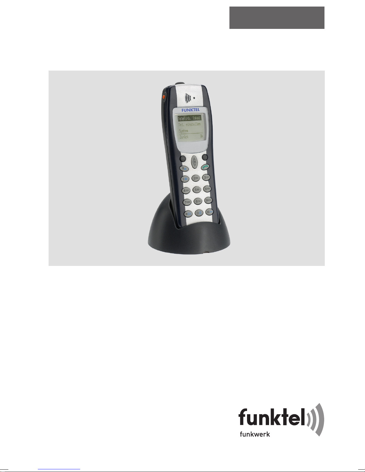
Business Handset FC1 / FC1 Ex (HS)
an Mobility-Server
I 33 / CS I55 und I 1/3/5
Funktel • Enterprise Networking
Kurz-Bedienungsanleitung
Quick Guide
Guide utilisateur
Order No.
50 1010 7101
V3.5
Page 2
FC1 / FC1 Ex
1
3
5
Mobility Server I 33 / CS I55 • I 1/3/5
F U N K T E L
1
2
4
6
8
9
11
13
14
7
O K
R
1
G H I
4
P Q R S
7
A B C
2
J K L
5
T U V
8
D E F
3
M N O
6
W X Y Z
9
0
10
12
15
1
Nicht für das FC1 Ex! Does not apply to FC1 Ex! N’est pas disponible
pour le combiné FC1 Ex!
2
16
Page 3

Mobility Server I 33 / CS I55 • I 1/3/5
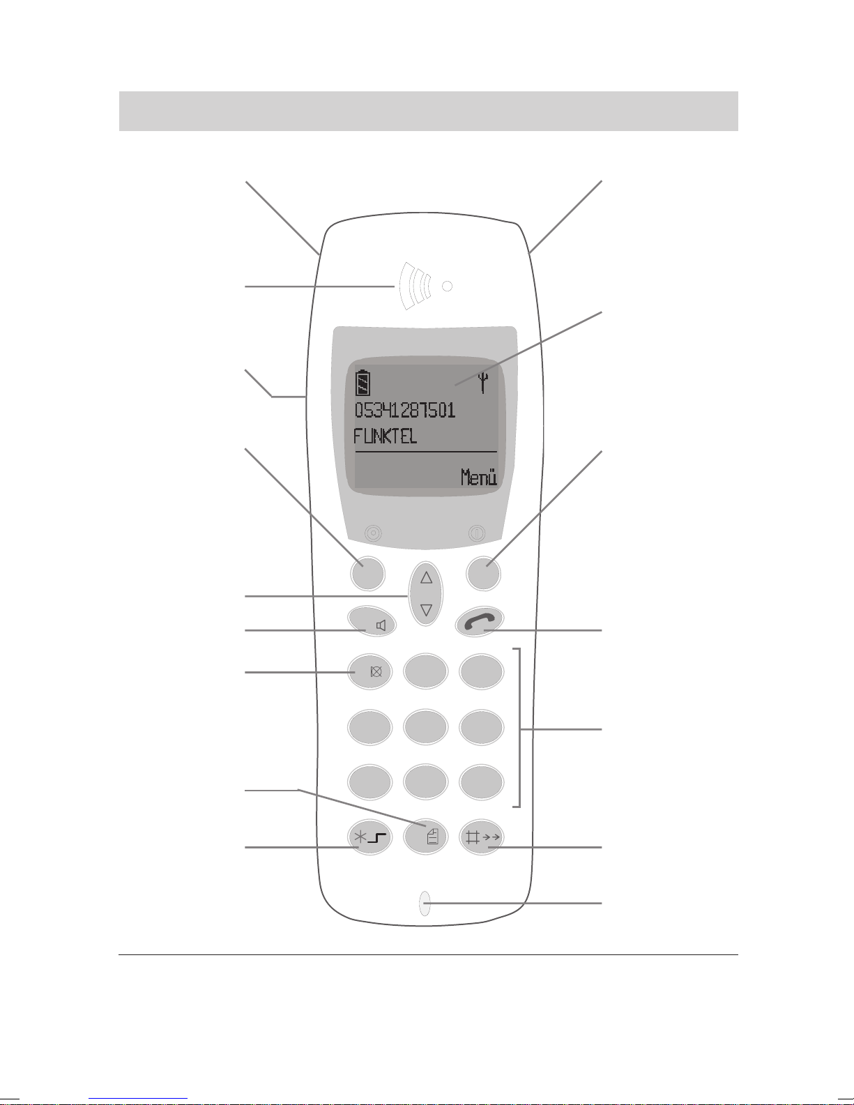
Legende / legend / légende
DGBF
1
2
3
4
5
6
7
8
9
10
11
12
13
14
15
16
Notruftaste
1
Buchse 1 für
Hör-/
Sprechgarnitur
Hörer
Display
Lautsprecher
für Freisprechen
Softkey links
Softkey rechts
1.: Selector
2.: Pfeiltasten
zum Blättern
im Menü
1.: Taste ‘R’
2.: Freisprechen
Taste Hörer
1.: Taste ‘1’
2.: Stummschaltung
Zifferntasten
1.: Taste ‘0’
2.: Telefonbuch oder
Anruf-/ Nachrichtenliste
1.: Taste Stern
2.: Softkey
umschalten
3.: Klein- /
Großbuchstaben
1.: Taste Raute
2.: Wahlwiederholung
Mikrofon
Emergency
call key
Socket 1 for
headset
Earpiece
Display
Loudspeaker
for handsfree
operation
Left softkey
Right softkey
1st: Selector
2nd: Arrow
keys for paging
through the
menu
1st: ‘R’ key
2nd:
Handsfree
operation
‘Hook on/off’
key
1st: ‘1’ key
2nd: Mute
Number keys
1st: ‘0’ key
2nd: T elephone book or
call/message
list
1st: ‘St ar’ key
2nd: Switch
softkey
3rd: Shift
1st: ‘Hash’ key
2nd: Redial
Microphone
Touche d’appel
d’urgence
Prise 1 pour
l’écouteur/
microphone
capsule
d’écoute
Afficheur
Haut-parleur
mains libres
Touche
programmable
de gauche
Touche progr.
de droite
1.: Touche OK
2.: Touche
fléchée pour
feuilleter dans
le menu
1.: Touche ‘R’
2.: Mains libres
Raccrocher /
décrocher le
combiné
1.: Touche ‘1’
2.: Muet
Touches
numériques
1.: Touche ‘0’
2.: Annuaire ou
liste d’appels /
de messages
1.: Touche
‘étoile’
2.: basculer les
touches progr.
3.: majuscules/
minuscules
1.: T ouche
‘dièse’
2.: répétition de
la numérotation
Microphone
3
Page 4

D Inhaltsverzeichnis
Mobility Server I 33 / CS I55 • I 1/3/5
Wichtige Hinweise 5
Inbetriebnahme 11
Display 14
Grundregeln für die Bedienung 16
Telefonieren wie gewohnt 19
Rückfrage und Weiterverbinden 20
Gespräche laut hören, Mikrofon 21
ausschalten
Business Handset einstellen 22
Sprache 23
GB Table Of Contents
Important information 45
Commissioning 51
Display 54
Basic rules of operation 56
Notruf 24
Messaging 25
Nachricht empfangen 26
Nachrichten- und Anrufliste 28
Nachricht senden 30
Technische Daten / Zubehör 34
Explosionsgeschützte Ausführung 36
FC1 Ex (HS) – Sicherheitshinweise 37
FC1 Ex (HS) – Inbetriebnahme 41
FC1 Ex (HS) – Technische Daten 43
Emergency call 64
Messaging 65
Receiving a message 66
Message-list and Call-list 68
Telephoning as usual 59
Refer-back call and call forwarding 60
Handsfree operation,
switch off the microphone 61
Setting the Business handset 62
Language 63
F Table de matières
Remarques importantes 84
Mise en service 91
Afficheur 94
Règles élémentaires d’utilisation 96
Téléphoner comme vous en avez
l’habitude 99
Double appel et transfert 100
Mains-libres,
désactiver le microphone 101
Configurer votre combiné 102
Langue 103
Sending a message 70
Technical specifications / Accessories 74
Explosion-Proof Version 76
FC1 Ex (HS) – Safety Instructions 77
FC1 Ex (HS) – Commissioning 80
FC1 Ex (HS) – Technical Specifications 82
Appel d’urgence 104
Messagerie 105
Recevoir des messages 106
Liste des messages et des appels 108
Emettre un message 110
Caractéristiques techn. / Accessoires 114
Version antidéflagrante 116
FC1 Ex – Consignes de sécurité 11 7
FC1 Ex – Mise en service 121
FC1 Ex (HS) – Caractéristiques
techniques / Accessoires 123
4
Page 5

Mobility Server I 33 / CS I55 • I 1/3/5
Wichtige Hinweise
Inhalt dieser Kurzbedienungsanleitung
In dieser Bedienungsanleitung finden Sie erklärt, wie Sie Ihr Business
Handset in Betrieb nehmen. Es werden alle Grundregeln zur Bedienung
und die am häufigsten genutzten Funktionen und Einstellungen beschrieben.
Eine vollständige Beschreibung aller anlagenspezifischen Funktionen finden Sie auf der mitgelieferten CD-ROM. Sie können die Bedienungsanleitungen ansehen und ausdrucken.
Lieferumfang eines Sets
Bitte kontrollieren Sie sofort den Lieferumfang, wenn Sie Ihr FC1 im Set
erhalten:
• Business Handset FC1 mit Bedienungshinweisen.
Explosionsgeschützte Geräte FC1 Ex sind ab Werk mit montiertem Klipp
ausgestattet, der nicht entfernt werden darf!
Eine Ausnahme ist im Abschnitt Sicherheitshinweise, Verwendung von
Tragetaschen, Ex-Geräte mit und ohne Klipp, beschrieben.
D
• MEM-Card
• Wechselakku. Explosionsgeschützte Geräte dürfen nur mit dem explo-
sionsgeschützten Akku, Artikelnummer 50 1014 8000, betrieben werden.
• Ladegerät. Für explosionsgeschützte Geräte darf nur das
Ladegerät FC1 S Ex, Artikelnummer 50 1018 1001, eingesetzt werden.
• Steckernetzgerät
• Diese Kurz-Bedienungsanleitung
• CD-ROM mit ausführlichen Bedienungsanleitungen
Die Komponenten dieses Sets sind einzeln erhältlich.
Wo Sie ihr Business Handset benutzen können
Das Business Handset FC1 ist für den Einsatz im Büro, im Freien oder in
staubiger Umgebung geeignet. Es entspricht der Schutzart IP 54
(spritzwasser- und staubgeschützt).
Schützen Sie sich vor Gehörschäden
Bringen Sie den Freisprechlautsprecher auf der Rückseite des Handsets
nicht in unmittelbare Ohrnähe!
Durch die Signalisierungslautstärke von mehr als 80 dB (A) kann es – bei
V 3.5 • 05/2005
5
Page 6

D
Mobility Server I 33 / CS I55 • I 1/3/5
Wichtige Hinweise
zu geringem Abstand zwischen Freisprechlautsprecher und Ohr oder bei
sehr häufiger Einwirkung – zu einem dauernden Gehörschaden kommen.
Umgang mit den Akkus
• Akkus nur sachgemäß einsetzen. Funktel übernimmt keine Haftung für
Schäden, die durch unsachgemäßen Umgang mit dem Akku entstehen.
Beachten Sie die Hinweise zum Akkugebrauch auf Seite 13!
• Sollten in Extremfällen Akkus undicht werden, müssen Sie mit dem
Austritt von Elektrolyten oder Gasen rechnen. Nehmen Sie das Gerät
außer Betrieb und geben Sie es an den Service. Hinweise auf Undichtigkeiten sind weißliche Beläge am Gehäuse oder auf dem Akku und
ungewohnte oder stechende Gerüche.
• Schützen Sie sich vor Verätzungen oder Vergiftungen indem Sie das
Einatmen austretender Gase und den direkten Hautkontakt mit ausgelaufenen Akkus vermeiden. Suchen Sie im Zweifelsfall einen Arzt auf!
• Bei Versand oder längerer Lagerung sind die Akkus vom Gerät zu
trennen, um Tiefentladung und Schädigung zu vermeiden.
• Werfen Sie den Akku nicht ins Feuer, er könnte explodieren.
• Achten Sie darauf, dass die Kontakte des Akkus nicht mit leitenden
Gegenständen (Metall, Draht) in Berührung kommen oder kurzgeschlossen werden. Es bestehen Brand- und Explosionsgefahr für den Akku und
das Gerät.
• Werfen Sie aufgebrauchte Akkus nicht in die Mülltonne! Bringen Sie sie
zu einer Sammelstelle Ihrer Gemeinde oder Ihrem Händler, damit sie
einer umweltgerechten Entsorgung zugeführt werden können. Bitte
entsorgen Sie nur entladene Akkus.
Pflegehinweise für NiCd- und NiMH-Akkus
Hier erfahren Sie, wie Sie die Leistungsfähigkeit der Akkupacks möglichst
lange erhalten können. Benutzen Sie zum Laden nur die systemkonforme
Ladestation!
1 Leere und volle Akkupacks ohne eingebaute Elektronik können Sie
getrennt von den Geräten bei einer Lagertemperatur von 0 °C bis 35 °C
über einen längeren Zeitraum (bis zu mehreren Jahren) ohne Schaden
lagern. Volle Akkus entleeren sich dabei selber innerhalb weniger Wochen bis Monate. Diese Selbstentladung ist unschädlich, da sie keine
Tiefentladung ist.
6
V 3.5 • 05/2005
Page 7

Mobility Server I 33 / CS I55 • I 1/3/5
Wichtige Hinweise
2 Akkupacks mit eingebauter Elektronik (z. B. Schutzschaltungen zur
Realisierung des Explosionsschutzes in Ex-Akkus) entleeren sich, auch
wenn sie vom Gerät getrennt sind, durch den Stromverbrauch der
eingebauten Elektronik mit der Zeit restlos und werden durch diese
Tiefentladung dauerhaft geschädigt. Um diese schädliche Tiefentladung
bei längerer Lagerung zu vermeiden, müssen Sie solche Akkupacks
einmal vor der Lagerung laden und danach regelmäßig alle 3 Monate.
Die zulässige Lagertemperatur für eine längere Lagerung liegt ebenfalls
im Bereich von 0 °C bis 35 °C.
3 Lassen Sie neue oder gelagerte Akkupacks grundsätzlich einmal ohne
jede Ladeunterbrechung aufladen, bevor Sie sie benutzen. Das gleiche
gilt für Akkus, deren Ladezustand Sie nicht kennen. Die empfohlenen
Ladezeiten finden Sie in der Bedienungsanleitung.
4 Sollten Sie feststellen, dass neue oder längere Zeit gelagerte Akkupacks
nach der ersten Aufladung (Punkt 3) die in der Bedienungsanleitung
Ihres Gerätes genannte Betriebszeit erheblich unterschreiten, wenden
Sie bitte die Akku-Kur nach Punkt 8 an.
D
5 Laden Sie erschöpfte Akkupacks umgehend. Oder trennen Sie sie
zumindest vom Gerät. Damit verhindern Sie eine Tiefentladung der
Akkupacks – Beachten Sie jedoch die Besonderheiten bei der Lagerung
von Akkupacks mit eingebauter Elektronik nach Punkt 2!
Erschöpfte Akkupacks erkennen Sie an der 'Batterie leer' - Meldung oder
an der nachlassenden Funktion Ihres Gerätes.
6 Sorgen Sie dafür, daß der Akkupack nicht ständig randvoll ist. Für das
akkubetriebene Gerät bedeutet das: Stellen Sie es nach wenigen und
kurzen Einsätzen nicht sofort wieder in seine Ladestation, sondern
lassen Sie es längere Zeit, z. B. über Nacht, betriebsbereit (stand-by)
neben der Ladestation liegen; möglichst bis zur 'Batterie leer' - Meldung
des Gerätes. Regelmäßiges vollständiges Entladen und Aufladen des
Akkupacks verhindert einen frühzeitigen Kapazitätsverlust der Zellen.
7 Vermeiden Sie den routinemäßigen Wechsel halbvoller oder gar fast
vollgeladener Akkupacks. Wenn ein routinemäßiger Akkuwechsel aus
betrieblichen Gründen erforderlich ist, sollten Sie die Wechselintervalle
so weit verlängern, dass der Akkupack möglichst weit entladen ist bevor
er gewechselt wird, ohne jedoch die sichere Funktion des Gerätes durch
einen erschöpften Akku zu gefährden (Betriebsreserve einplanen!).
V 3.5 • 05/2005
7
Page 8

D
Mobility Server I 33 / CS I55 • I 1/3/5
Wichtige Hinweise
8 Lassen die Betriebszeiten des Gerätes mit einer Akku-Ladung nach länge-
rer Gerätenutzung erheblich nach, versuchen Sie es mit der Akku-Kur:
Entladen: Benutzen Sie das Gerät (Mobilteil) bis zur 'Batterie leer' -
Meldung.
Aufladen: Laden Sie den Akku auf, wie es in der Bedienungsanleitung
beschrieben ist.
Wiederholen Sie diesen Zyklus (Entladen, Aufladen) noch mehrere Male.
Mit jedem Durchgang gewinnt der Akku einen Teil seiner ehemaligen
Aufnahmekapazität zurück.
9 Nachteilige, von Funktel nicht zu verantwortende Einflüsse für die
Lebensdauer eines Akkupacks sind:
Extreme Kälte und starke Erwärmung bei Lagerung oder im Betrieb,
Ständiger Aufenthalt in der Ladestation,
Tiefentladung im Gerät oder bei Lagerung.
Umgang mit den Ladegeräten
• Alle Schutzkontaktsteckdosen für die Steckernetzteile müssen sich in
der Nähe der anzuschließenden Ladegeräte befinden und jederzeit
zugänglich sein. Die Schutzkontaktsteckdosen müssen vorschriftsmäßig
durch Fachpersonal installiert worden sein.
Bevor Sie das Netzteil in die Steckdose stecken: Überzeugen Sie sich
davon, dass die vorhandene Netzspannung mit den Angaben auf dem
Steckernetzteil (z. B. 230 V, 50 Hz) übereinstimmt.
• Ladegeräte und Steckernetzteile enthalten keine Teile, die gewartet
(gepflegt) werden können.
Reparaturen müssen vorschriftsmäßig durch geschultes Fachpersonal
ausgeführt werden. Lassen Sie defekte oder beschädigte Ladegeräte/
Netzteile — auch bei beschädigter Anschlussschnur — nur gegen
Originalteile austauschen.
• Vorsicht beim Umgang mit beschädigten Netzteilen!
Schalten Sie die Steckdose spannungsfrei (Sicherung des zuständigen
Stromkreises entfernen oder ausschalten) bevor Sie ein mechanisch
beschädigtes Steckernetzteil aus der Steckdose ziehen!
Das Berühren netzspannungsführender Teile ist lebensgefährlich!
8
V 3.5 • 05/2005
Page 9

Mobility Server I 33 / CS I55 • I 1/3/5
Wichtige Hinweise
• Die Ladegeräte sind für den Betrieb in büroähnlicher Umgebung ausge-
legt. Schützen Sie sie vor starkem Schmutzanfall, Staub, Feuchtigkeit
und Nässe sowie vor direkter Wärmestrahlung.
Das Handset vor Eingriffen und Umwelteinflüssen schützen
• Das Gehäuse des Handsets niemals aufschrauben! Das Gehäuse kann
sonst beschädigt werden. Es enthält keine Teile, die Sie reparieren
können.
• Schützen Sie das Gerät vor extremen Umgebungseinflüssen (z. B. vor
Temperaturen außerhalb der Temperaturangaben in den technischen
Daten, vor länger andauernder direkter Sonneneinstrahlung)
• Setzen Sie das Gerät keinen extrem starken magnetischen Feldern aus,
wie sie z. B. in der Nähe von Induktionsschmelzöfen und Elektroschweißeinrichtungen auftreten können!
D
Andere Geräte vor Funktionsstörungen durch das Handset schützen
In der Regel sind andere elektronische Geräte vor Hochfrequenz-Einstrahlung geschützt. Falls aber ein solches Gerät unzureichend abgeschirmt ist,
kann es zu Fehlfunktionen kommen, die durch einen ausreichend großen
Abstand zwischen beiden Geräten behoben werden können.
Tipps zum Aufstellort
Verwenden Sie für Ihr Ladegerät eine rutschfeste Unterlage, besonders
bei neuen oder mit Pflegemitteln behandelten Möbeln. Lacke oder Pflegemittel können Stoffe enthalten, die die Füße Ihres Ladegeräts aufweichen,
und die aufgeweichten Gerätefüße könnten auf der Oberfläche der Möbel
unerwünschte Spuren hinterlassen. Funktel kann für derartige Schäden
nicht haften.
Allgemeine Zulassung und Konformität
Die Funktel GmbH erklärt, dass das Produkt FC1 mit den grundlegenden
Anforderungen und anderen relevanten Bestimmungen der Richtlinie
1999/5/EU (R&TTE) übereinstimmt.
Dieses Gerät ist zum Anschluss an Funk-Schnittstellen (DECT
TM
) von
Funktel Mobility Servern bestimmt und erfüllt die grundlegenden Anforde-
DECT
TM
ist ein eingetragenes Warenzeichen der ETSI
9
Page 10
D
Mobility Server I 33 / CS I55 • I 1/3/5
Wichtige Hinweise
rungen gemäß der EG-Richtlinie 1999/5/EG (Radio und Telekommunikation Terminal Equipment, R&TTE).
Dieses Gerät ist bauartbedingt nicht zum direkten Betrieb an Schnittstellen
öffentlicher Telekommunikationsnetze vorgesehen.
Falls beim Betrieb dennoch Probleme auftreten sollten, wenden Sie sich
bitte zunächst an Ihren Fachhändler oder an den Funktel Service.
Die Konformitätserklärung kann über die E-Mail-Adresse [email protected]
angefordert werden.
Diese Einrichtung arbeitet nach dem System DECT
1880 MHz bis 1900 MHz. Die Ausweisung dieses Frequenzbereichs im
Frequenznutzungsplan gilt zunächst bis 2008 und wird in Abhängigkeit von
der europäischen Harmonisierung fortgeschrieben.
TM
im Frequenzbereich
-Zulassung und EG-Baumusterprüfbescheinigung für die
explosionsgeschützten Geräteausführungen
Für den Gas-Explosionsschutz nach ATEX gilt die EG-Baumusterprüfbescheinigung TÜV 03 ATEX 2244 X mit der Kennzeichnung
II 2 G EEx e ib IIC T4
für einen Umgebungstemperaturbereich Ta= – 10 °C ... + 55 °C.
Für den Staub-Explosionsschutz nach ATEX gilt die EG-Baumusterprüfbescheinigungsnummer IBExU03ATEX1216 X mit der Kennzeichnung
II 2 D IP 65 T80 °C
für einen Umgebungstemperaturbereich Ta= – 10 °C ... + 55 °C.
DECT
TM
ist ein eingetragenes Warenzeichen der ETSI
10
Page 11

Mobility Server I 33 / CS I55 • I 1/3/5
Inbetriebnahme
Wenn Ihr Business Handset noch nicht montiert ist
Wenn Sie das Business Handset nicht komplett montiert erhalten, müssen
Sie
• die MEM-Card einsetzen (siehe Seite 12),
• den Akku einbauen (siehe Seite 12) und
• gegebenenfalls noch die Schutzfolie vom Display abziehen.
• Schließlich muss Ihr Service das Business Handset an Ihrer Telefonanla-
ge anmelden.
Danach ist Ihr Business Handset betriebsbereit.
• Schließen Sie jetzt noch das Ladegerät an (siehe Seite 13).
Wenn Ihr Business Handset schon komplett montiert ist
D
Wenn Sie Ihr Business Handset schon komplett montiert erhalten und es
an Ihrer Telefonanlage angemeldet ist, dann brauchen Sie nur das Ladegerät anzuschließen (siehe Seite 13).
MEM-Card
Sie können mit Ihrem Business Handset nur telefonieren, wenn eine MEMCard eingelegt ist. Wichtige Daten Ihres Handsets, sowie persönliche
Einstellungen und Ihr persönliches Telefonbuch, sind darauf gespeichert.
Bei einem Wechsel des Handsets entnehmen Sie die MEM-Card aus
Ihrem bisherigen Handset und setzen sie in das neue Handset ein. Sie
können das neue Handset mit dieser MEM-Card sofort benutzen.
Achtung!
Beachten Sie die Sicherheitshinweise für den Umgang mit
explosionsgeschützten Geräten auf den Seiten 36 bis 40.
11
Page 12
D
Mobility Server I 33 / CS I55 • I 1/3/5
Inbetriebnahme
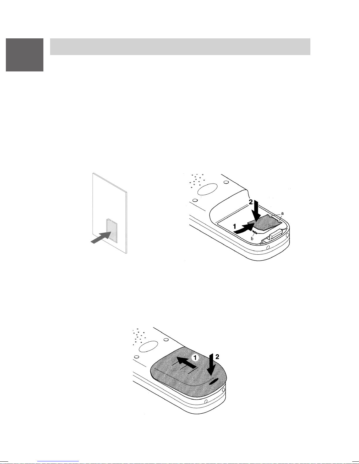
MEM-Card einlegen
• Drücken Sie zunächst die kleine MEM-Card mit dem Finger aus dem
größeren Rahmen heraus (nachstehende Abbildung links).
• Schieben Sie die MEM-Card mit der kurzen Kante schräg unter die
Halte-Halbmonde a im MEM-Card-Fach (nachstehende Abbildung
rechts) (1). Die goldglänzenden Kontaktflächen der MEM-Card müssen
nach unten weisen!
• Drücken Sie die MEM-Card nach unten, bis die kleine Rastnase b fasst
(2).
Akku einsetzen
• Akku in das Gehäuse schieben (1)
• Akku an der Riegelseite nach unten drücken bis er hörbar einrastet (2).
12
Page 13
Mobility Server I 33 / CS I55 • I 1/3/5
Inbetriebnahme
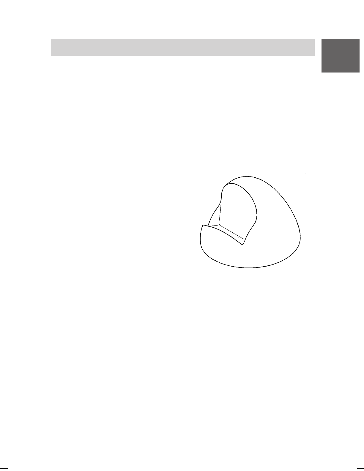
Ladegerät aufstellen
Stellen Sie das Ladegerät auf eine feste, ebene Unterlage, z. B. auf einen
Tisch. Wählen Sie einen Standplatz, der vor direkter Sonneneinstrahlung
und Feuchtigkeit geschützt ist.
• Stecken Sie das Steckernetzteil in eine Steckdose.
• Stecken Sie den kleinen Stecker der Anschlussschnur hinten in das
Ladegerät. Hinweis: Das Ladegerät Plus darf nur mit dem Stecker-
netzgerät Plus benutzt werden!
Das Ladegerät ist nun betriebsbereit.
Business Handset aufladen
S tellen Sie das Business Handset in
das Ladegerät. Sie hören einen
Bestätigungston. Die Display-Beleuchtung geht kurz an.
D
Das Business Handset bleibt einoder ausgeschaltet, entsprechend
dem Zustand, in dem es vor der
Ablage im Ladegerät war.
Das Akku-Symbol in der Symbolzeile
bewegt sich, bis der Akku voll geladen
ist. Während des Aufladens werden die Akkus leicht warm. Das ist normal.
Hinweise zum Akkugebrauch
Stellen Sie das Business Handset nach jedem Einsetzen eines Akkus für
mindestens 14 Stunden in das Ladegerät um den Akku vollständig
aufzuladen. Stellen Sie das Business Handset in der ersten Betriebswoche
immer wieder in das Ladegerät. Neue Akkus erreichen ihre volle Kapazität
in der Regel erst nach einigen Tagen normalen Gebrauchs.
Sie können Ihr Business Handset dauerhaft im Ladegerät stehen lassen.
Der Akku kann nicht überladen werden.
Lassen Sie den Akku nicht in der prallen Sonne liegen. Er dankt es Ihnen
mit einer langen Lebensdauer.
Ladegerät
13
Page 14
D
Mobility Server I 33 / CS I55 • I 1/3/5
Display
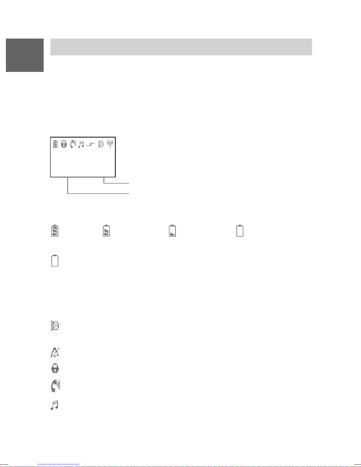
Texte und Symbole im Display helfen Ihnen bei der Bedienung. Sie werden
durch die Menüs geführt und über den Zustand Ihres Handsets informiert.
Die Funktionen der Softkeys links und rechts ändern sich je nach Zustand.
Die aktuellen Softkey-Funktionen werden im Display direkt über den
Tasten angezeigt.
Die Zeilen im Display
Symbolzeile zeigt den Zustand des Telefons an.
M u s t e r m a n n
2 7 3 4
T r e n n e n M e n ü
Zwei Textzeilen z. B. für Name und Rufnummer.
Funktion des rechten Softkeys z. B. Menü
Funktion des linken Softkeys z. B. Trennen
Bedeutung der Symbole
Akku voll, Akku fast voll, Akku fast leer, Akku leer,
Akkusymbol blinkt: Kapazität für weniger als fünf Minuten!
Bitte beachten Sie: Wenn Sie einen Akkku einlegen, ist dessen
Ladezustand dem Business Handset zunächst unbekannt. Deshalb
wird kein Akkusymbol angezeigt. Die Anzeige erscheint erst, wenn der
Akku mit dem Business Handset mindestens 14 Stunden ohne
Unterbrechung im Ladegerät geladen wurde.
Stumm: Das Mikrofon ist aus. Ihr Gesprächspartner kann Sie nicht
hören.
Kein Anrufsignal: Anrufsignal ist auf stumm gestellt.
Schloss: Das Business Handset ist abgeschlossen.
Hörer: Das Business Handset hat eine Telefonverbindung.
Mehrfrequenzwahlverfahren (MFV): Jeder Tastendruck wird als DTMF-
Ton (hörbar) an den Verbindungsteilnehmer übertragen (MFV-Nachwahl).
14
Page 15
Mobility Server I 33 / CS I55 • I 1/3/5
Display
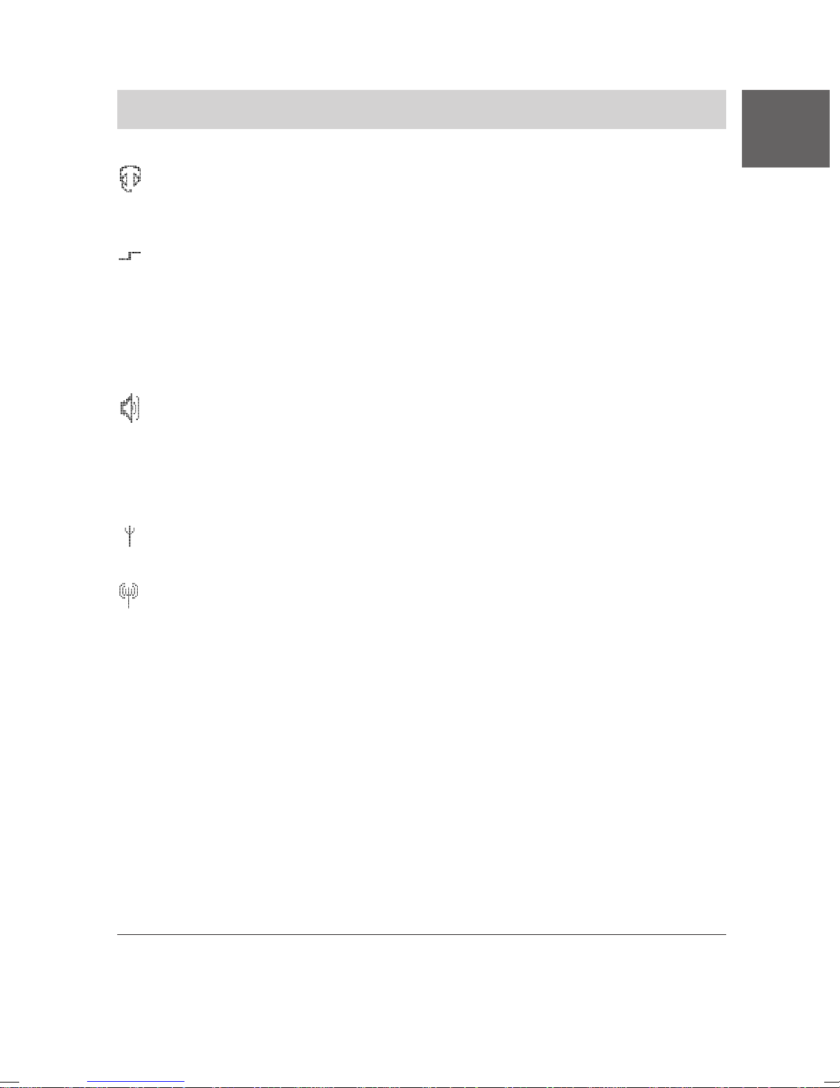
Hör-/Sprechgarnitur: Sie telefonieren mit Hilfe der Hör-/Sprech-
garnitur. Gehäusemikrofon und -lautsprecher sind automatisch abgeschaltet.
Sonderfunktion 1 eingeleitet: Taste Stern wurde lange gedrückt,
während Sie sich in einer Texteingabefunktion, z. B. Telefonbucheintrag, befinden. Dieser Tastendruck wechselt zwischen Groß- und
Kleinschreibung ... oder
Taste S tern wurde lange gedrückt (bis zum tiefen Bestätigungs-Beep), um
eine Tastatursperre oder deren Aufhebung einzuleiten.
Lautsprecher: Der Lautsprecher für das Freisprechen auf der
Gehäuserückseite ist eingeschaltet.
Bringen Sie den Freisprechlautsprecher auf der Rückseite des
Handsets nicht in unmittelbare Ohrnähe! Siehe Warnhinweis auf
Seite 5.
D
In Reichweite der Anlage: Ihr Business Handset ist in Reichweite
einer Basisstation. Sie können telefonieren.
V erbindung zur Anlage: Ihr Business Handset hat eine Funkverbindung.
LIST
In der Anrufliste steht ein unbearbeiteter Anruf.
MAIL
In der Nachrichtenliste steht mindestens eine ungelesene Textnachricht.
mail
In der Nachrichtenliste steht mindestens eine gelesene Textnachricht.
mail, LIST
Es gibt gelesene Textnachrichten und mindestens einen unbearbeiteten Anruf.
MAIL, LIST
Es gibt mindestens eine ungelesene Textnachricht und mindestens
einen unbearbeiteten Anruf.
1
Langer Tastendruck: Taste gedrückt halten, bis ein tiefer Bestätigungston
ertönt!
15
Page 16
D
Mobility Server I 33 / CS I55 • I 1/3/5
Grundregeln für die Bedienung
Für die Bedienung Ihres Business Handsets gibt es einige Schritte, die
häufig vorkommen. Machen Sie sich mit diesen Bedienschritten vertraut.
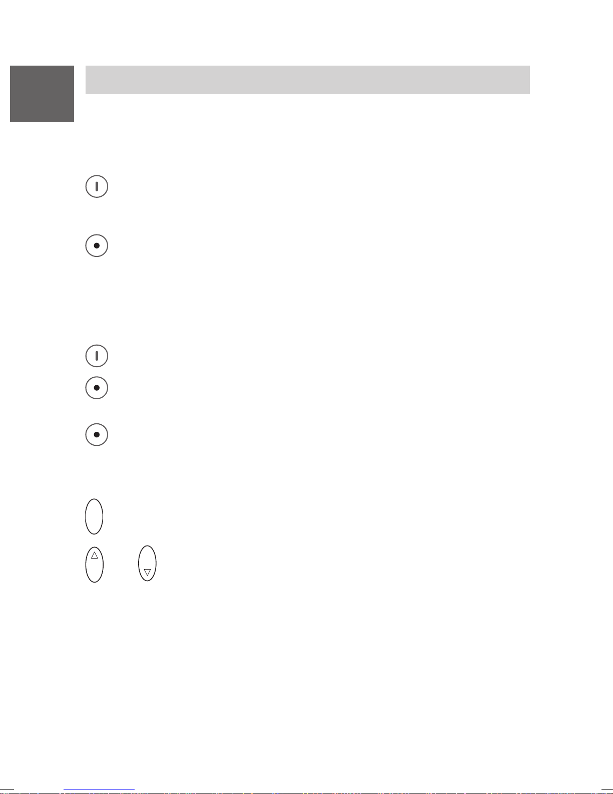
Business Handset einschalten
Das Business Handset ist aus. Softkey rechts lange drücken.
Business Handset ausschalten
Das Business Handset ist im Grundzustand. Softkey links lange
drücken.
Linker und rechter Softkey
Die Funktion der Softkeys wechselt je nach Situation. Die Funktion steht
immer im Display über der Taste, z. B. Menü oder Trennen.
Der Softkey rechts dient zum Einschalten oder zum Menüaufruf.
Der Softkey links dient zum Beenden eines Menüpunkts oder zum
Abbrechen.
Wenn Sie den Softkey links in irgendeinem Menü lange drücken,
geht das Business Handset in den Grundzustand.
Selector
O K
O K
Damit schließen Sie die Einstellvorgänge ab.
oder
O K
Auf den oberen oder unteren Pfeil des Selectors drücken, um
in einem Menüangebot oder in einer Nachrichten- oder Anrufliste zu
blättern.
Doppelt belegte Tasten
Einige Tasten Ihres Handsets sind mit zwei Funktionen belegt. Diese
erkennen Sie an den zusätzlichen blauen Aufdrucken. Wenn Sie die
zweite blaue Funktion auslösen wollen, müssen Sie die Taste länger
drücken. Sie hören einen tiefen Bestätigungston.
16
Page 17
Mobility Server I 33 / CS I55 • I 1/3/5
Grundregeln für die Bedienung
Menü auswählen
Einige Funktionen und Einstellungen Ihres Business Handsets können Sie
über die Anzeige (Menü) im Display erreichen. Das Menü ist so strukturiert, daß sich hinter den meisten Menüpunkten weitere Untermenüs
befinden.
Menü aufrufen 1 mit Softkey rechts.
D
O K
oder
O K
Auf den oberen oder unteren Pfeil des Selectors drücken, um
den gewünschten Menüpunkt zu markieren, z. B. System.
O K
Auf die Mitte des Selectors drücken, um den Menüpunkt auszuwählen.
Menü-Ebene zurück
Mit dem Softkey links gelangen Sie eine Menüebene höher oder
verlassen das Menü.
Untermenüs
Untermenüs werden genauso bedient, wie das Hauptmenü.
Abbrechen
Drücken Sie den Softkey links lange, um in den Grundzustand zu
gelangen.
Tastatursperre mit Tastenfolge einschalten
R
Ü
S perren: Taste Stern lange, dann Taste R drücken.
Tastatursperre aufheben
R
Ü
1
Sie können im Grundzustand auch gleich auf den unteren Pfeil des
Aufheben: Taste S tern lange, dann Taste R drücken.
Selectors drücken, um das Menü aufzurufen.
17
Page 18
D
Mobility Server I 33 / CS I55 • I 1/3/5
Grundregeln für die Bedienung
Hörerlautstärke während eines Gespräches vorübergehend ändern
1
Die Grundeinstellung
Stufe 6 (laut) verändern, wie im Abschnitt Telefon einstellen beschrieben.
Sie können diese Einstellung bei Bedarf während eines Telefonates
vorübergehend ändern:
Sie telefonieren normal oder mit eingeschaltetem Lautsprecher für
das Freisprechen.
Lautstärke vorübergehend erhöhen
der Hörerlautstärke läßt sich von Stufe 1 (leise) bis
O K
Länger auf den oberen Pfeil des Selectors drücken, bis Sie einen
tiefen Bestätigungston hören. Die Lautstärke erhöht sich um eine
Stufe. Vorgang wiederholen, bis die gewünschte Lautstärke erreicht
ist.
Lautstärke vorübergehend verringern
O K
Länger auf den unteren Pfeil des Selectors drücken, bis Sie einen
tiefen Bestätigungston hören. Die Lautstärke verringert sich um eine
Stufe. Vorgang wiederholen, bis die gewünschte Lautstärke erreicht
ist.
Die neue Einstellung bleibt nur für das aktuelle Gespräch bestehen. Beim
nächsten Gespräch ist wieder die ursprünglich voreingestellte Lautstärke
für den Hörer und den Freisprech-Lautsprecher wirksam.
1
Die variable Grundeinstellung für die Hörerlautstärke beeinflusst nicht
die Grundeinstellung für den Lautsprecher beim Freisprechen.
18
Page 19
Mobility Server I 33 / CS I55 • I 1/3/5
7
P Q R S
Telefonieren wie gewohnt
Sie können mit Ihrem Business Handset ganz normal telefonieren.
Innerhalb Ihrer Telefonanlage (intern): Wählen Sie gleich die Durchwahl-
nummer.
Außerhalb Ihrer Telefonanlage (extern): Wählen Sie erst die Amts-
kennziffer (meist die Null) und dann die Rufnummer Ihres Gesprächspartners.
Anrufen
Abheben.
D
A B C
1
2
M N O
Rufnummer wählen, z. B. 1276
6
Gespräch beenden
Auflegen.
Wahlwiederholung
1
Abheben.
#
Taste Raute lange drücken.
Einen Anruf annehmen
Ihr Business Handset klingelt.
Abheben.
Hinweis:
Wenn Sie während eines Gespräches eine Nachricht (Message) erhalten,
wird diese Gesprächsverbindung nicht unterbrochen.
Siehe Abschnitt Messaging .
1
An dem Mobility Server I 1/3/5 können Sie die Wahlwiederholung nur bei
externen Anrufen nutzen.
V 3.5 • 05/2005
19
Page 20
D
Mobility Server I 33 / CS I55 • I 1/3/5
Rückfrage und Weiterverbinden
Beim Telefonieren können Sie in Rückfrage gehen und mit einem anderen
telefonieren. Ihr Gesprächspartner wartet dann. – Außerdem können Sie
den Anrufer weiterverbinden.
Rückfrage einleiten
Sie telefonieren.
R
7
Rückfrage einleiten. Ihr Gesprähspartner hört Sie nicht.
P Q R S
M N O
6
J K L
5
G H I
Gewünschte Rufnummer eingeben, z. B. 7654.
4
Im Display steht die Nummer 7654. Die Verbindung wird aufgebaut.
Ihr erster Gesprächspartner wartet.
Rückfrage beenden
R
Zum ersten Gesprächspartner zurück 1 mit der Taste R.
Einen Anrufer weiterverbinden
Sie telefonieren.
R
7
Rückfrage einleiten.
P Q R S
M N O
6
J K L
5
G H I
Gewünschte Rufnummer eingeben, z. B. 7654.
4
Auflegen 2.
1
Am Mobility Server I 1/3/5 wird die Verbindung zum Rückfrageteilnehmer
getrennt, wenn Sie die Rückfrage beenden.
2
Sie können weiterverbinden, ohne abzuwarten, bis der dritte abhebt.
20
Page 21
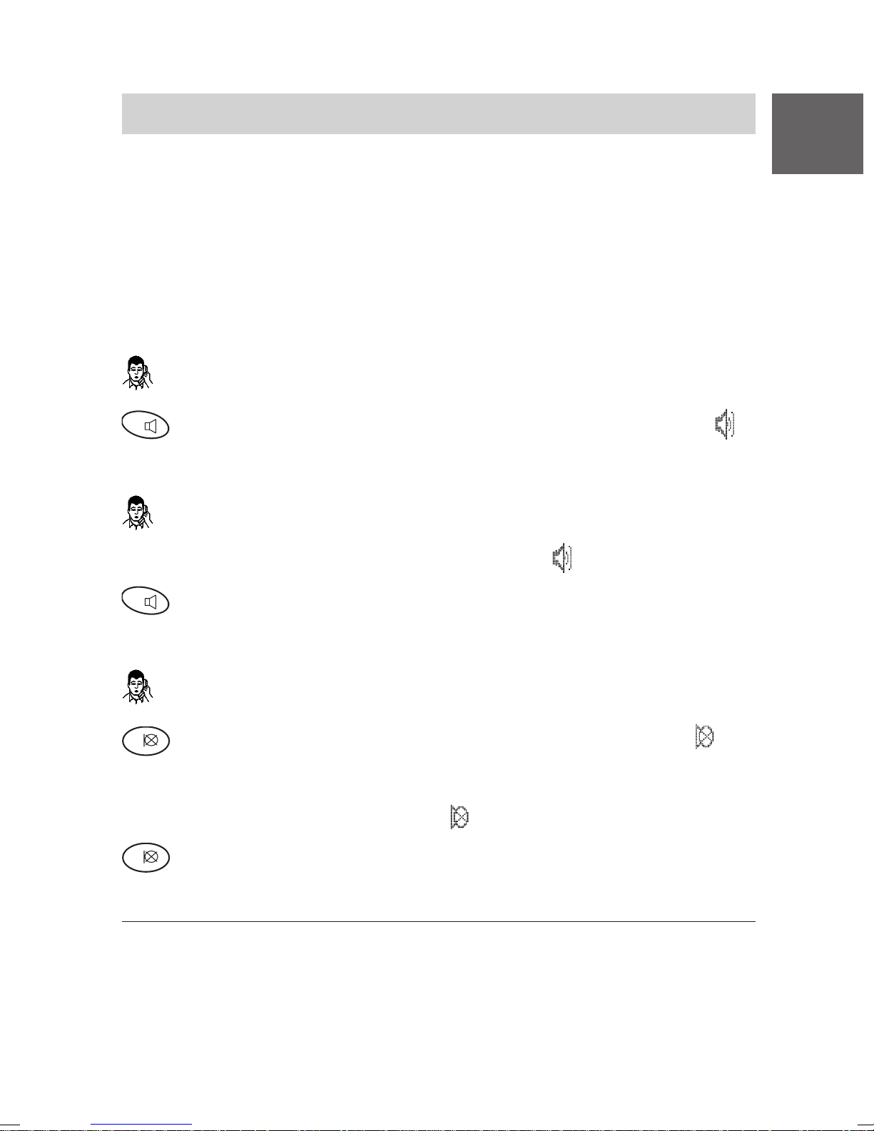
Mobility Server I 33 / CS I55 • I 1/3/5
Gespräche laut hören, Mikrofon ausschalten
Sie können den eingebauten Lautsprecher für Freisprechen einschalten.
Ihren Gesprächspartner hören Sie dann laut im Raum und Sie können frei
sprechen.
Beim Telefonieren können Sie das Mikrofon an Ihrem Business Handset
ausschalten. Der Hörer bleibt dabei eingeschaltet. Ihr Gesprächspartner
hört Sie nicht, aber Sie ihn.
Lautsprecher für Freisprechen einschalten
Sie telefonieren.
D
R
Lautsprecher für Freisprechen wieder ausschalten
R
Mikrofon ausschalten (stumm schalten)
1
Mikrofon wieder einschalten
Das Mikrofon ist aus. Im Display steht
Lautsprecher einschalten: Taste R lange drücken. Im Diplay steht .
Sie telefonieren. Das Gespräch wird über den Lautsprecher für das
Freisprechen wiedergegeben. Im Diplay steht .
Lautsprecher ausschalten: Taste R lange drücken.
Sie telefonieren.
Mikrofon ausschalten: Taste 1 lange drücken. Im Display steht .
.
1
Mikrofon einschalten: Taste 1 lange drücken. Sie können das Telefonat
fortsetzen.
Bei Gesprächsende wird der Lautsprecher für das Freisprechen automatisch ausgeschaltet und das Mikrofon automatisch wieder eingeschaltet.
Wenn Sie während eines Gesprächs Ihr Business Handset in das
Ladegerät stellen, wird automatisch Freisprechen eingeschaltet.
21
Page 22
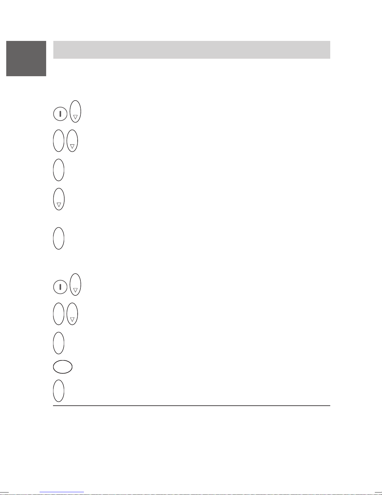
D
Mobility Server I 33 / CS I55 • I 1/3/5
Business Handset einstellen
Im Grundzustand können Sie Einstellungen am Handset vornehmen.
Anrufsignal
O K
Menü Tel. einstellen.
O K
O K
Menü Anrufsignal.
O K
O K
Bestätigen.
Gewünschte Rufeinstellung, z. B.Anrufton. Sie haben die Wahl
zwischen Anrufton, Vibrieren
O K
Bestätigen.
Rufton-Lautstärke
O K
Menü Tel. einstellen.
O K
O K
Menü Rufton-Lautstärke.
O K
Bestätigen.
1
, beides, Anrufton kurz oder stumm 2.
D E F
3
O K
1
Rufton-Lautstärke eingeben (von 0 bis 9), z. B. 6.
Bestätigen.
Im Ladegerät vibriert Ihr Business Handset nicht. Wenn Sie als Anrufsignal Vibrieren gewählt haben, ertönt bei einem Anruf der Anrufton kurz.
2
Wenn Sie als Anrufsignal stumm gewählt haben, erscheint ein entsprechendes Symbol im Display (siehe Abschnitt Display auf Seite 14).
22
Page 23
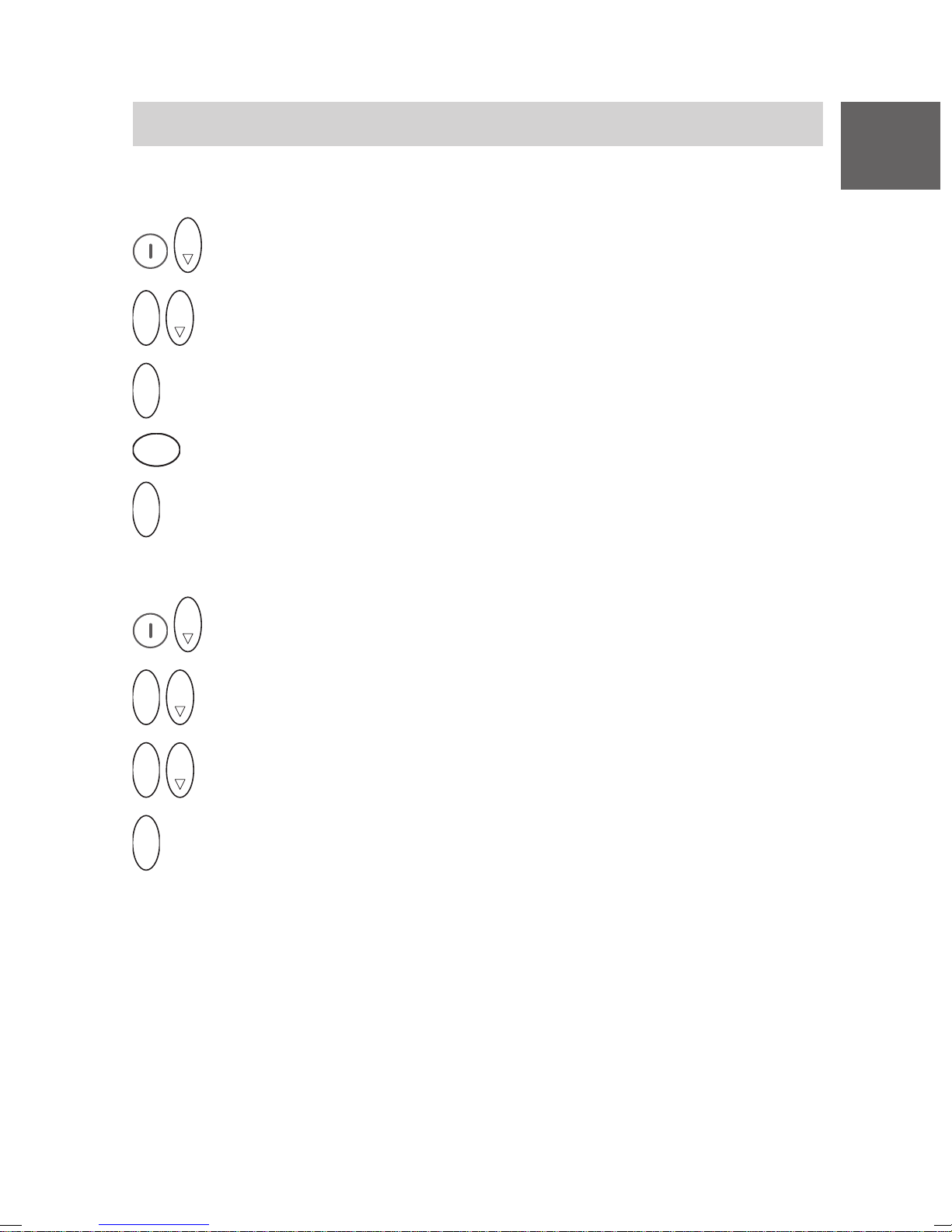
Mobility Server I 33 / CS I55 • I 1/3/5
Business Handset einstellen
Hörerlautstärke
O K
Menü Tel. einstellen.
O K
O K
Menü Lautstärke Hörer.
D
O K
3
O K
Bestätigen.
D E F
Hörerlautstärke eingeben (von 1 bis 6), z. B. 3.
Bestätigen.
Sprache des Lokalmenüs festlegen
O K
Menü Tel. einstellen.
O K
O K
Menü Sprache.
O K
O K
Sprache auswählen, z. B. Deutsch.
O K
Bestätigen.
23
Page 24
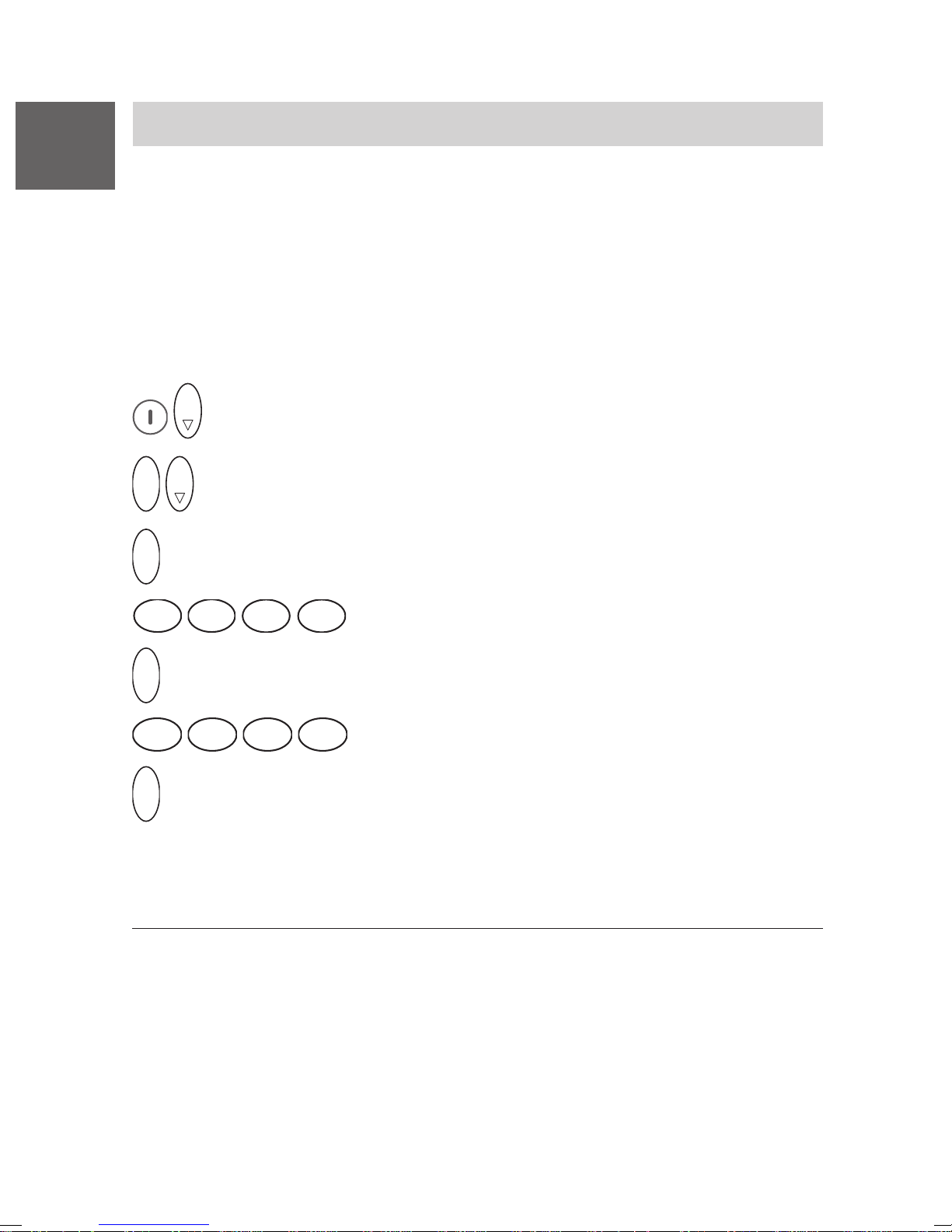
D
Mobility Server I 33 / CS I55 • I 1/3/5
Notruf
Wenn Ihr Business Handset abgeschlossen ist, funktioniert nur noch die
Notrufnummer. Im Display steht über dem rechten Softkey: SOS
Notrufauslösungen mit der roten Notruftaste links oben an der Gehäuseseite sind immer möglich – auch bei nicht abgeschlossenem Handset.
Notrufauslösungen bei abgeschlossenem Business Handset sind außerdem möglich durch zweimaligen Druck auf die SOS-Taste Softkey rechts.
Notrufnummer einrichten und ändern
O K
Menü Tel. einstellen.
O K
O K
Menü Notrufnummer.
1
.
O K
2
O K
6
O K
Bestätigen.
A B C
3
Bestätigen.
M N O
6
Bestätigen.
D E F
M N O
G H I
4
M N O
6
J K L
PIN eingeben, z. B. 2345.
5
M N O
Notrufnummer eingeben oder ändern 2, z. B. 6666.
6
Notruf absetzen mit der Notruftaste
Notruftaste auf der Oberseite lange drücken. Die Notrufnummer wird
gewählt.
1
Der Notruf SOS steht nicht zur Verfügung, wenn keine Notrufnummer
eingegeben ist, während ein Gespräch geführt wird, wenn ein Anruf oder
eine Message ankommt, oder wenn das Business Handset außer
Reichweite der Telefonanlage ist.
2
Notrufnummer löschen: Gehen Sie vor wie beim Ändern. Löschen Sie
die angezeigte Telefonnummer mit einem langen Druck auf den Softkey
links und bestätigen mit dem Selector oder mit der Taste Softkey rechts.
24
Page 25

Messaging mit Mobility Server I 33 / CS I55
Messaging
Das Messaging 1 erlaubt Ihnen, mit Ihrem Business Handset kurze Nachrichten zu empfangen oder zu senden.
Sie können Nachrichten an einzelne Teilnehmer oder an Gruppen senden.
Die Rufnummer eines Teilnehmers kann im Einzelfall von seiner Telefonnummer abweichen.
Die Nachrichten sind Festtexte. Bei Bedarf können Sie beliebige Ziffern
nachwählen. Die Liste der Festtexte erhalten Sie von Ihrem Systemverwalter.
Erfolgskontrolle für den Absender:
Der Absender erhält eine Bestätigung, ob die Übermittlung der Nachricht
erfolgreich war, und ggf. ob der Empfang quittiert wurde.
Die letzten 10 Nachrichten werden in einer Nachrichtenliste gespeichert.
Sie können direkt aus der Liste zurückrufen.
D
Hinweis:
Während des Empfangs einer Nachricht und während einer eventuell
erforderlichen manuellen Quittierung bleibt eine bestehende Gesprächsverbindung erhalten. Der Gesprächspartner hört die die Signalisierung der
Message.
Beispiel:
Teilnehmer A und Teilnehmer B führen ein Telefongespräch. Teilnehmer A
empfängt eine Nachricht (Message), begleitet von einem Aufmerksamkeitssignal.
Die Gesprächsverbindung bleibt während der Übertragung der Message
und während einer eventuell erforderlichen manuellen Quittierung durch
den Teilnehmer A bestehen. Das Handsetmikrofon des Teilnehmers A
bleibt eingeschaltet, so dass der Teilnehmer B das Geschehen beim
Teilnehmer A mithören kann.
Das Gespräch kann nach Ende der Signalisierung und Quittierung fortgesetzt werden.
1
Die Messaging Funktionen stehen Ihnen nur an einem Mobility Server
I 33 / CS I55 mit angeschlossenem Message Server zur Verfügung.
Der Message Server ist eine Ergänzung zu Ihrem Mobility Server.
Beachten Sie die Kopfzeile mit der Angabe zu den Mobility Servern.
V 3.5 • 05/2005
25
Page 26
D
Messaging mit Mobility Server I 33 / CS I55
Nachricht empfangen
Ihr Business Handset klingelt mit einem besonderen Rufton 1.
Im Display steht ggf. die Telefonnummer des Absenders und die Nachricht.
z. B. 5371 Meeting in room 109.
Solange die Nachricht zu sehen ist, haben Sie folgende Möglichkeiten:
• Rufton ausstellen
R
Taste R drücken.
• Nachricht aus dem Display löschen
Softkey links drücken. Die Nachricht geht in die Nachrichten-Liste.
Im Ruhe-Display steht mail.
• Nachricht endgültig löschen
0
Taste 0 drücken.
oder ...
Ü
Taste Stern lange drücken, dann Softkey links drücken.
• Manuell bestätigen
Wichtige Nachrichten haben vorne ein Ausrufezeichen, z. B. ! Meeting.
Sie müssen manuell bestätigt werden.
• Manuell bestätigen, positiv
Im Display steht eine Nachricht mit Ausrufezeichen, z. B. ! Meeting in
room 109. Sie müssen manuell bestätigen.
1
Die Ruftöne unterscheiden sich je nach Dringlichkeit.
26
Page 27
Messaging mit Mobility Server I 33 / CS I55
Ü
Nachricht empfangen
Softkey links drücken. Im Display steht +++OK, wenn die positive
Quittung erfolgreich abgeschickt wurde.
• Manuell bestätigen, negativ
Im Display steht eine Nachricht mit Ausrufezeichen, z. B. ! Meeting in
room 109. Sie müssen manuell bestätigen.
D
Ü
Stern (kurz) drücken. Im Display steht –––OK, wenn die negative
Quittung erfolgreich abgeschickt wurde.
Ü
Tasten Stern (lange), Softkey rechts, Stern (kurz),
27
Page 28
D
Messaging mit Mobility Server I 33 / CS I55
Nachrichten- und Anrufliste
Nachrichtenliste
1
Die letzten 10 Nachrichten werden in der Nachrichtenliste
abgelegt. Der Text mail in der zweiten Displayzeile kennzeichnet eine
gelesene Mail-Liste, der Text MAIL (in Großbuchstaben) weist auf mindestens eine ungelesene Mail hin. Schauen Sie unbedingt in die Liste!
Anrufliste
Nicht angenommene Anrufe werden in einer Anrufliste gespeichert (Liste
mit den 10 letzten Anrufen). Sie können aus der Anrufliste zurückrufen.
Der Text LIST weist auf mindestens einen noch nicht zur Kenntnis genom-
menen Anruf hin. Wurden alle Anrufe in der Liste zur Kenntnis genommen,
entfällt der Text LIST. Die letzten 10 Anrufe bleiben in der Anrufliste gespeichert, wenn sie nicht manuell gelöscht werden.
Nachrichten-Liste / Anruf-Liste einsehen oder zur Einsicht auswählen
(Mail-Speicher)
Im Ruhe-Display steht MAIL LIST, MAIL, LIST, mail LIST, oder mail.
Entweder Taste
O K
... oben auf den Selector drücken.
lange drücken, oder ...
0
Enthält nur eine der beiden Listen Einträge, wird diese Liste sofort
geöffnet. Sie können jetzt mit weiteren Tastendrücken oben oder
unten auf den Selector in den Listeneinträgen der geöffneten Liste
blättern. Siehe nächste Seite!
Enthalten beide Listen Einträge, erscheint auf dem Display die
Anzeige Mail-Liste, und Sie können mit weiteren Tastendrücken
oben oder unten auf den Selector zwischen Mail-Liste und Anruf-
Liste wechseln.
Wählen Sie die Mail- oder Anruf-Liste aus und
O K
Bestätigen Sie die ausgewählte Liste mit dem Selector , um sie zu öffnen.
1
Ein Eintrag in der Nachrichten-Liste enthält Absender-Nummer, Text, Tag
und Uhrzeit sowie die Anzahl der Zustellversuche. Bei mehreren Zustellversuchen der gleichen Nachricht beziehen sich die Angaben zu Tag und
Uhrzeit immer auf den jüngsten Versuch.
28
Page 29
Messaging mit Mobility Server I 33 / CS I55
Nachrichten- und Anrufliste
Blättern in einer geöffneten Liste
D
O K
oder
O K
Zum Blättern oben oder unten auf den Selector drücken. Im
Display steht z. B. 6789 Konferenz 15.05 12:26.
Falls die Nachricht nicht in eine Zeile passt
Wenn die Nachricht aus mehr als 16 Zeichen besteht, so wird sie zunächst
abgekürzt in der 1. Displayzeile dargestellt. Sie können sich die maximal
32 Zeichen
#
1
lange Nachricht anzeigen lassen.
Taste Raute lange drücken. Anstelle der Datumsangabe erscheint in
der 2. Displayzeile der Rest der Nachricht.
Nachricht oder Anruf aus einer Liste löschen
Nachricht oder Anruf anzeigen lassen, dann ...
0
Taste 0 drücken.
oder ...
Ü
Taste Stern lange drücken, dann Softkey links drücken.
Rückruf zu einem Anrufer aus der Anrufliste oder zum Absender
einer Nachricht, falls die Nachricht von einem Business Business
Handset gesendet wurde
Anruf oder Nachricht anzeigen lassen, dann ...
Abheben mit Taste Hörer.
1
Ist die empfangene Nachricht länger als 32 Zeichen, wird die Nachricht
nach dem 31. Zeichen abgeschnitten. Das 32. Zeichen ist ein Punkt um
zu kennzeichnen, dass ein Teil der Nachricht abgeschnitten wurde.
29
Page 30
D
Messaging mit Mobility Server I 33 / CS I55
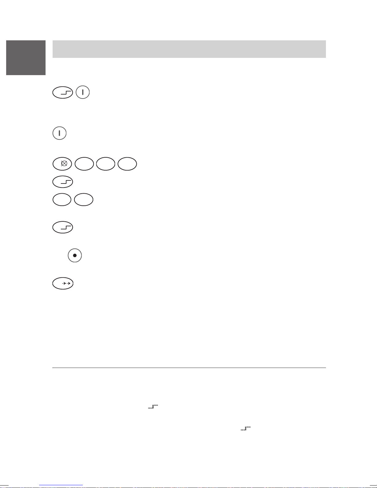
Nachricht senden
Festtext
Ü
1
senden
Taste Stern lange, dann Softkey recht s drücken. Im Display steht
Mail-Adresse.
oder
Softkey rechts lange drücken. Im Display steht Mail-Adresse.
dann
A B C
1
Ü
7
2
Taste Stern drücken. Im Display steht 1234*.
P Q R S
T U V
8
D E F
3
G H I
Nummer eingeben, z. B. 1234.
4
Nummer des Festtextes eingeben, z. B 78. Im Display steht
1234*78.
Ü
Taste Stern drücken. Im Display steht der Festtext, z. B. 1234*Mee-
ting in Room.
(Mit
Softkey links können Sie ggf. korrigieren und eine andere Num-
mer für einen anderen Festtext eingeben.)
Taste Raute drücken. Im Display steht für kurze Zeit Message
#
wird gesendet.
Erfolgskontrolle
Wie auf der nächsten Seite (Seite 31) beschrieben!
1
Die Festtexte sind zentral gespeichert. Eine Liste der Festtexte erhalten
Sie von Ihrem Systemverwalter.
Sie können einen Nachrichten-Sendevorgang vollständig im Telefonbuch
lokal abspeichern, z. B.
, #, 1234, Stern, 78, Stern, Stern, 109, #. Das
ist sinnvoll z. B. für Notrufe!
Die im Telefonbucheintrag abgelegte Tastenfolge
, # leitet bei einer
Rufauslösung das Messaging ein.
30
Page 31
Messaging mit Mobility Server I 33 / CS I55
Nachricht senden
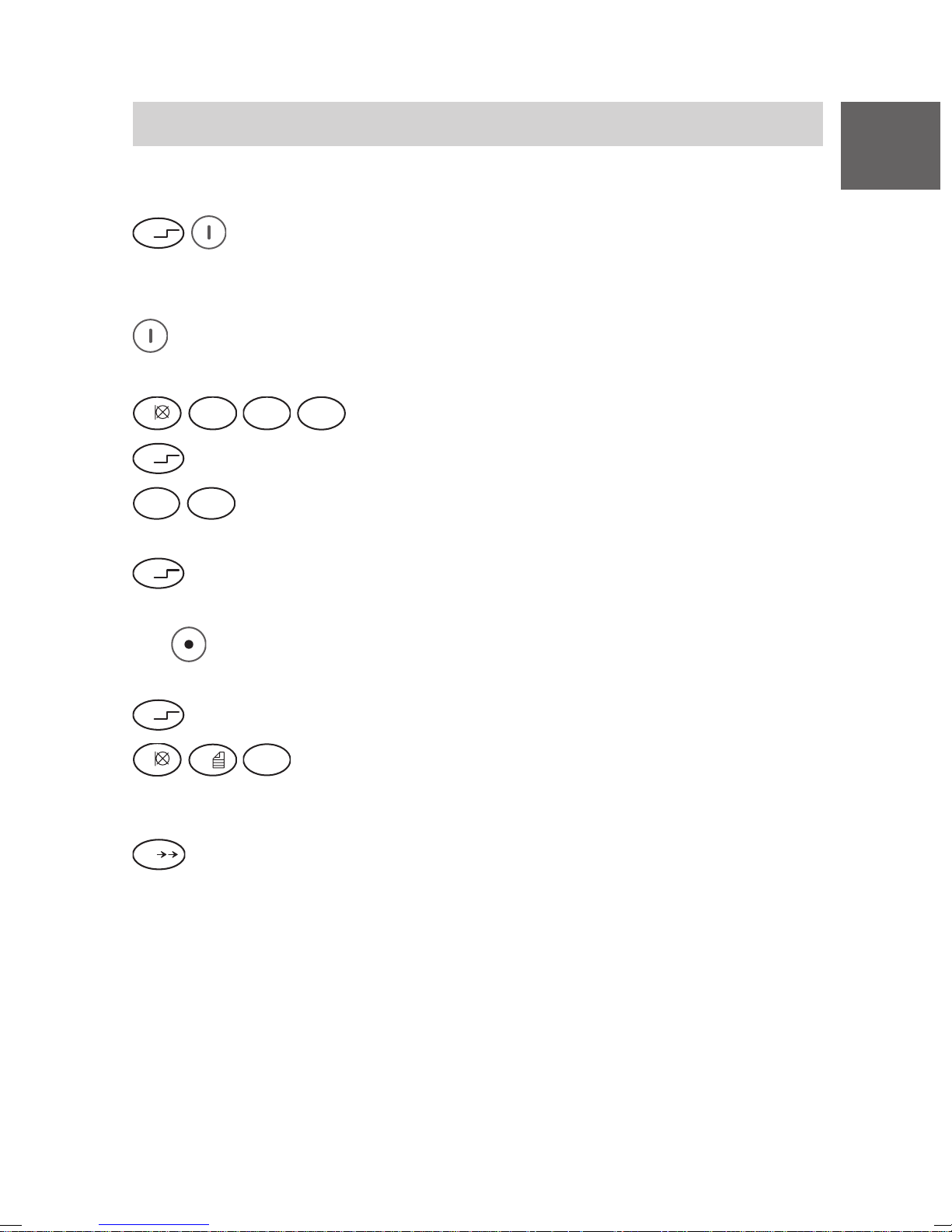
Festtext senden mit nachgewählten Ziffern
D
Ü
Taste Stern (lange), dann Softkey recht s drücken. Im Display steht
Mail-Adresse.
oder
Softkey rechts lange drücken. Im Display steht Mail-Adresse.
dann
A B C
1
Ü
7
2
Taste Stern drücken. Im Display steht 1234*.
P Q R S
T U V
8
D E F
3
G H I
Nummer eingeben, z. B. 1234.
4
Nummer des Festtextes eingeben, z. B 78. Im Display steht
1234*78.
Ü
Taste Stern drücken. Im Display steht der Festtext, z. B. 1234*Mee-
ting in Room.
(Mit
Softkey links können Sie ggf. korrigieren und eine andere Num-
mer für einen anderen Festtext eingeben.)
Ü
Taste Stern drücken.
1
0
W X Y Z
9
gewünschte Ziffern nachwählen, z. B. 109. Im Display
steht der Festtext, gefolgt von den nachgewählten Ziffern, z. B.
1234*Meeting in Room 109.
Taste Raute drücken. Im Display steht für kurze Zeit Message wird
#
gesendet.
Erfolgskontrolle
Bei Erfolg steht im Display nach kurzer Zeit POS Meeting ... .
Wenn der Teilnehmer negativ bestätigt oder nicht erreichbar ist, steht im
Display nach kurzer Zeit NEG Meeting ... .
Falls der Teilnehmer nicht bekannt ist oder auf eine Nachricht mit Aufforderung zur manuellen Bestätigung nicht reagiert hat, steht im Display nach
kurzer Zeit ??? Meeting ... .
31
Page 32
D
Messaging mit Mobility Server I 33 / CS I55
Nachricht senden
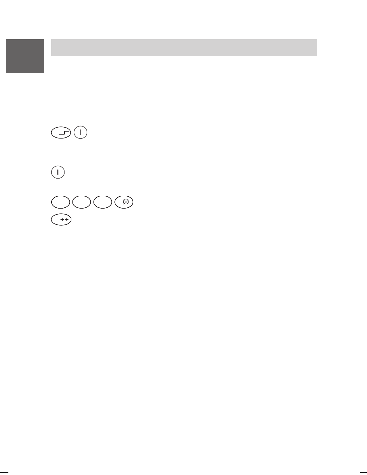
Direktruf senden
Beim Direktruf senden Sie mit einer festen Direktruf-Nummer einen festgelegten Text an einen festgelegten Empfänger (Einzelteilnehmer oder
Gruppe). In diesem Beispiel lautet der Direktruf: Direktruf-Text.
Eine Liste mit Direktruf-Nummern erhalten Sie von Ihrem Systemverwalter.
Ü
Taste Stern (lange), dann Softkey recht s drücken. Im Display steht
Mail-Adresse.
oder
Softkey rechts lange drücken. Im Display steht Mail-Adresse.
dann
G H I
4
#
D E F
3
Taste Raute drücken.
A B C
2
Direktruf-Nummer eingeben, z. B. 4321.
1
Erfolgskontrolle
Bei Erfolg steht im Display nach kurzer Zeit POS Direktruf-Text.
Wenn der Teilnehmer negativ bestätigt oder nicht erreichbar ist, steht im
Display nach kurzer Zeit NEG Direktruf-Text.
Falls der Teilnehmer nicht bekannt ist oder auf eine Nachricht mit Aufforde-
rung zur manuellen Bestätigung nicht reagiert hat, steht im Display nach
kurzer Zeit ??? Direktruf-Text.
32
Page 33
Messaging mit Mobility Server I 33 / CS I55
Nachricht senden
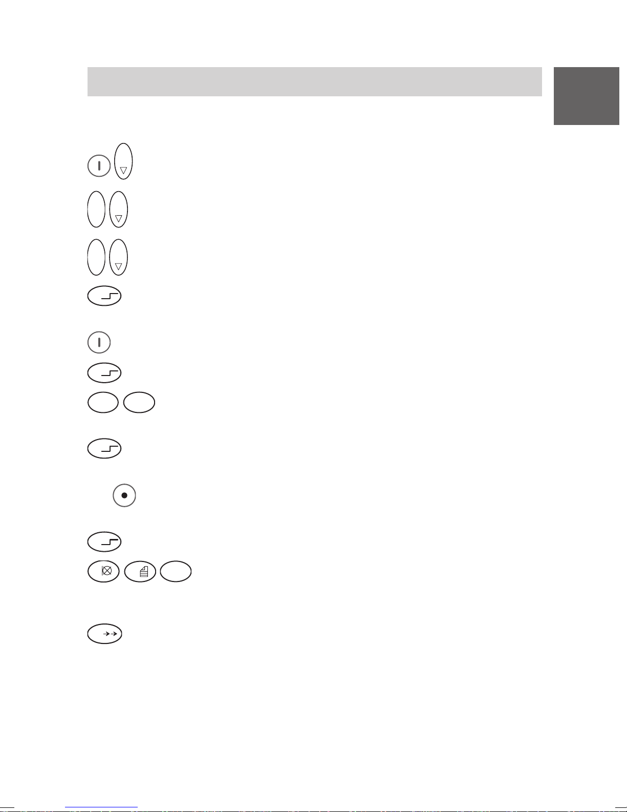
Festtext mit Telefonbuch lokal senden
O K
Menü Telefonbuch lokal.
O K
O K
Menü Suchen.
O K
O K
Eintrag suchen, z. B. Meier.
D
Ü
Ü
P Q R S
7
Ü
(Mit
Ü
1
Taste Stern lange drücken. Im Display steht bei Softkey rechts
Msg.to.
Softkey rechts drücken. Im Display steht z. B. 1234 Mail-Adresse.
Taste Stern drücken. Im Display steht 1234*.
T U V
Nummer des Festtextes eingeben, z. B 78. Im Display steht
8
1234*78.
Taste Stern drücken. Im Display steht der Festtext, z. B. 1234*Mee-
ting in Room.
Softkey links können Sie ggf. korrigieren und eine andere Num-
mer für einen anderen Festtext eingeben.)
Taste Stern drücken.
0
W X Y Z
gewünschte Ziffern nachwählen, z. B. 109. Im Display
9
steht der Festtext, gefolgt von den nachgewählten Ziffern, z. B.
1234*Meeting in Room 109.
Taste Raute drücken. Im Display steht für kurze Zeit Message wird
#
gesendet.
Erfolgskontrolle
Wie auf Seite 31 beschrieben!
33
Page 34

D
Mobility Server I 33 / CS I55 • I 1/3/5
Technische Daten / Zubehör
Business Handset FC1
Nicht für Betrieb in explosionsgefährdeten Bereichen außer Zone 2 und
Zone 22 nach Vorgaben in der Herstellererklärung!
Standard: DECT
TM
(Digital Enhanced
Cordless Telecommunications)
Maße: 138 mm x 47 mm x 21 mm plus Antenne
Gewicht, Handset: ca. 109 g (mit Akku)
Akkutyp: NiMH; 650 mAh
Betriebsdauer Handset Sprechen: 8 Stunden
(mit vollem Akku): Stand-by: 80 Stunden
Ladezeit: ca. 5 Stunden
Frequenzbereich: 1,88 GHz ... 1,9 GHz
Sendeleistung: Mittelwert: 10 mW; Spitzenwert: 250 mW
Zulässige Handset: – 10 °C bis + 45 °C
Betriebstemperatur: Ladeschale: + 5 °C bis + 40 °C
Lagertemperatur: – 25 °C bis + 55 °C (Kurzzeitlagerung,
maximal 1 Monat)
0 °C bis + 35 °C (Langzeitlagerung)
Transporttemperatur: – 20 °C bis + 60 °C
Ruftonlautstärke 1: maximal 81 dB SPL in 30 cm Entfernung von
Notruf-Signalisierungs- 79 dB SPL in 30 cm Entfernung von
Lautstärke 1: der Schallquelle
Schutzart
Zubehör Ladegeräte
1
SPL ist der unbewertete Sound Pressure Level.
2
Die Schutzart IP 54 gilt nur, so lange die Anschlussbuchse für die Hör- /
Sprechgarnitur durch den Original-Dichtungsstöpsel verschlossen ist!
3
Einige Teile des Zubehörs müssen gesondert bestellt werden.
34
der Schallquelle
2
: IP 54; staub- und spritzwassergeschützt
3
: Ladegerät für das Laden eines
FC1-Handsets
Steckernetzgerät für Europa
Steckernetzgerät für Großbritannien
V 3.5 • 05/2005
Page 35

Mobility Server I 33 / CS I55 • I 1/3/5
Technische Daten / Zubehör
Zubehör Ladegeräte 3: Ladegerät Plus für das Laden eines
FC1-Handsets und eines Reserveakkus
Steckernetzgerät Plus für Europa
Steckernetzgerät Plus für Großbritannien
Sonstiges Zubehör 3: Wechselakku
Hör-/Sprechgarnitur (nur für das FC1)
Tragetasche
MEM-Card-Manager
D
V 3.4 • 04/2004
35
Page 36

D
Mobility Server I 33 / CS I55 • I 1/3/5
FC1 Ex (HS) – Explosionsgeschützte Ausführungen
Übersicht über Änderungen und Ergänzungen zu den explosionsgeschützten Geräteausführungen FC1 Ex und FC1 Ex HS
Sicherheitshinweise
Für den sicheren Umgang mit explosionsgeschützten Geräten in einer
explosionsgefährdeten Umgebung haben wir für Sie wichtige Sicherheitshinweise zusammengestellt. Lesen und befolgen Sie unbedingt diese
Hinweise, bevor Sie sich mit einem explosionsgeschützten FC1 Ex (HS) in
einen explosionsgefährdeten Bereich begeben.
Inbetriebnahme
Der Akku wird mit einer Sicherungsschraube am Gehäuse festgeschraubt.
Das FC1 Ex (HS) hat ein eigenes, besonders ausgestattetes Ladegerät
mit einem eigenen Steckernetzteil. Andere Ladegeräte und Steckernetzteile – zum Beispiel die für das FC1 – dürfen nicht zum Laden des
FC1 Ex (HS) benutzt werden.
Telefonieren / Messaging
Die Bedienung der Telefon- und Messagingfunktionen ist bei den Geräteausführungen FC1 und FC1 Ex (HS) gleich.
Technische Daten
Die explosionsgeschützten Ausführungen FC1 Ex / FC1 Ex HS haben
größere Gehäusemaße, ein geringfügig größeres Gewicht und etwas
geringere Sprech- und Stand-by-Zeiten als das Business Handset FC1.
Zubehör
Im Unterschied zum Business Handset FC1 haben die explosionsgeschützten Ausführung FC1 Ex / FC1 Ex HS ...
• ein besonderes Ladegerät mit der Artikelnummer 50 1018 1001 und ein
dazu passendes Steckernetzteil mit der Artikelnummer 4 999 070 859.
Für den Einsatz in Großbritannien gibt es ein Steckernetzteil UK. Fragen
Sie Ihren Händler.
• einen explosionsgeschützten Akku mit der Artikelnummer 50 1014 8000
• Das FC1 Ex darf nur ohne Hör- / S prechgarnitur betrieben werden. Die
Anschlussbuchse ist dauerhaft verschlossen und darf nicht entfernt werden.
• Für das FC1 Ex HS gibt es eine Hör-/Sprechgarnitur mit der Artikel-
nummer 50 1010 5101. Lesen Sie die Sicherheitshinweise!
36
V 3.4 • 04/2004
Page 37

Mobility Server I 33 / CS I55 • I 1/3/5
FC1 Ex (HS) – Sicherheitshinweise
Vorschriften und Bestimmungen
• Alle Geräte und Akkus tragen das CE-Konformitätszeichen.
In explosionsgefährdeten Bereichen dürfen nur explosionsgeschützte
Geräte mit den dazu gehörenden explosionsgeschützten Akkus eingesetzt werden. Diese Geräte und Akkus tragen eine Ex-Kennzeichnung.
• Diese Anleitung ist kein Ersatz für die vom Betreiber aufzustellenden
Betriebsanweisungen.
• Die Ladegeräte sind nicht explosionsgeschützt und dürfen daher
nur außerhalb explosionsgefährdeter Bereiche installiert und
betrieben werden!
Benutzung von Geräten in explosionsgefährdeten Bereichen
In explosionsgefährdeten Bereichen dürfen nur Geräte betrieben werden,
die den grundlegenden Sicherheits- und Gesundheitsanforderungen der
Richtlinie 94/9/EG entsprechen. Explosionsgeschützte Geräte, die diese
Anforderungen erfüllen, tragen das CE-Konformitätszeichen, gefolgt von
der Kenn-Nummer der benannten Stelle, die das Qualitätssicherungs-
D
system überwacht, sowie das Ex-Schutz-Zeichen
Gefährdungsgrad in explosionsgefährdeten Bereichen
Es gibt explosionsgefährdete Bereiche (Zonen) mit unterschiedlichem
Gefährdungsgrad. Die Geräte dürfen nur in denjenigen Zonen betrieben
werden, die keinen höheren Gefährdungsgrad aufweisen, als durch die
Herstellerangabe von Gerätegruppe und Kategorie auf dem Gerät ausgewiesen ist. Für die Festlegung der Zonen ist der Betreiber der Geräte und
der Secury-Anlage verantwortlich.
Akkus für explosionsgeschützte Geräte
Betreiben Sie explosionsgeschützte Geräte nur mit den dazu passenden
und zugelassenen explosionsgeschützten Akkus! Die zulässige Kombination von Gerät und Akku erkennen Sie anhand der Beschriftung auf dem
Gerätegehäuse. Die Verwendung anderer, nicht ausdrücklich zugelassener Akkus ist strengstens untersagt, da anderenfalls die Betriebserlaubnis
der Geräte in explosionsgefährdeten Umgebungen auf Grund des fehlenden Ex-Schutzes erlischt und das Gerät ein Sicherheitsrisiko darstellt!
Zugelassene Kombination:
Explosionsgeschützte Geräte dürfen nur mit dem Ex-Akku Artikelnummer 5 010 148 000 betrieben werden.
.
37
Page 38

D
Mobility Server I 33 / CS I55 • I 1/3/5
FC1 Ex (HS) – Sicherheitshinweise
Akkus wechseln, Akkus aufladen
Die Akkus der Ex-Geräte dürfen nur außerhalb der explosionsgefährdeten
Bereiche gewechselt werden. Der Betreiber der Anlage und Geräte trägt
die Verantwortung dafür, dass ein Akkuwechsel mit der nötigen Sorgfalt
ausgeführt wird und die konstruktiven Sicherheitsvorkehrungen – hier die
korrekte Verschraubung des Akkus durch die Sicherungsschraube –
befolgt werden. In explosionsgefährdeten Bereichen dürfen Sie Akkus
nicht vom Gerät trennen. Laden Sie die Akkus nur außerhalb der
explosionsgefährdeten Bereiche. Verwenden Sie nur das systemkonforme
Ladegerät FC1 S Ex mit der Artikelnummer 50 1018 1001. Die Verwendung anderer Ladeeinrichtungen ist strengstens untersagt, da die Akkus
überhitzt und geschädigt werden könnten.
Verwendung von Tragetaschen, Ex-Geräte mit und ohne Klipp
Sollen in explosionsgefährdeten Bereichen Geräte mit einer Tragetasche
verwendet werden, gibt es zwei Möglichkeiten:
• Verwendung eines explosionsgeschützten Gerätes mit Klipp zusammen
mit einer Tragetasche Artikelnummer 50 1011 7500
• Verwendung eines explosionsgeschützten Gerätes ohne Klipp in einer
Tragetasche Artikelnummer 50 1011 7501
Achtung: Explosionsgeschützte Geräte ohne Klipp dürfen nur in der
speziellen Tragetasche mit der Artikelnummer 50 1011 7501 in explosionsgefährdete Bereiche eingebracht und dort betrieben werden.
Außerdem müssen folgende Bedingungen erfüllt sein:
1 Nur eine Elektrofachkraft mit speziellen Kenntnissen des Explosions-
schutzes darf den Klipp eines explosionsgeschützten Gerätes entfernen
oder anbringen.
2 Das explosionsgeschützte Gerät ohne Klipp muss in die spezielle Trage-
tasche mit der Artikelnummer 50 1011 7501 gesteckt werden, bevor es in
explosionsgefährdete Bereiche eingebracht wird.
3 Es muss sichergestellt sein, dass das Gerät ohne Klipp in explosions-
gefährdeten Bereichen nicht aus der Tragetasche mit der Artikelnummer
50 1011 7501 entnommen wird.
Der Einsatz fremder Schutz- oder Tragetaschen kann ein Explosionsrisiko
darstellen und ist daher unzulässig!
38
V 3.5 • 05/2005
Page 39

Mobility Server I 33 / CS I55 • I 1/3/5
FC1 Ex (HS) – Sicherheitshinweise
Arbeiten am explosionsgeschützten Gerät
Alle Arbeiten am Gerät sowie das Aufladen und der Wechsel der Akkus
müssen außerhalb der explosionsgefährdeten Bereiche ausgeführt werden.
Das Öffnen der Geräte darf nur durch Fachkräfte im Sinne der
DIN EN 60079-17 erfolgen.
Wiederinbetriebnahme nach einem Eingriff in das Gerät
Nach jedem Eingriff in ein Gerät (Reparatur, Akkuwechsel) muss eine
zugelassene Prüfstelle vor der Wiederinbetriebnahme vorschriftsmäßig
festgestellt und dokumentiert haben, dass das betroffene Gerät in den für
den Explosionsschutz wesentlichen Merkmalen den Anforderungen der
BetrSichV entspricht. (BetrSichV = Verordnung über Sicherheit und
Gesundheitsschutz bei der Bereitstellung von Arbeitsmitteln und deren
Benutzung bei der Arbeit, über Sicherheit beim Betrieb überwachungsbedürftiger Anlagen und über die Organisation des betrieblichen Arbeitsschutzes).
D
Beschädigte Geräte
Offensichtlich oder auch nur vermutlich beschädigte Geräte dürfen nicht in
explosionsgefährdete Bereiche eingebracht werden. Befindet sich ein
offensichtlich oder vermutlich beschädigtes Gerät in einem explosionsgefährdeten Bereich, muss es sofort ausgeschaltet und aus dem
explosionsgefährdeten Bereich entfernt werden. Eine unbeabsichtigte
Wiederinbetriebnahme muss unbedingt verhindert werden.
Erlöschen der Ex-Betriebserlaubnis
Durch jede Änderung am Gerät oder an Teilen des Gerätes, die nicht vom
Hersteller genehmigt ist, erlischt die Betriebserlaubnis des Gerätes. Das
Gerät darf dann nicht in explosionsgefährdete Bereiche eingebracht oder
dort betrieben werden.
Verwendung des Headsets in explosionsgefährdeten Bereichen
Die Verwendung einer Hör- / Sprechgarnitur (Headset) an der explosionsgeschützten Geräteausführung FC1 Ex ist nicht zulässig!
Zur Wahrung des Explosionsschutzes ist der Dichtungsstöpsel fest in die
Anschlussbuchse eingeklebt. Bei Entfernung dieses Stöpsels erlischt die
Ex-Betriebserlaubnis des explosionsgeschützten Gerätes.
V 3.5 • 05/2005
39
Page 40

D
Mobility Server I 33 / CS I55 • I 1/3/5
FC1 Ex (HS) – Sicherheitshinweise
Die explosionsgeschützten Handsets mit der Typenbezeichnung
FC1 Ex HS dürfen nur mit der Hör-/Sprechgarnitur Artikelnummer
50 1010 5101 betrieben werden.
Der Explosionsschutz dieses Handsets FC1 Ex HS ist auf den GasExplosionsschutz beschränkt. Wird dieses Handset ohne Hör-/Sprechgarnitur betrieben, muss die Anschlussbuchse mit dem Originalstöpsel
verschlossen sein. Anderenfalls erlischt die Ex-Betriebserlaubnis.
40
Page 41
Mobility Server I 33 / CS I55 • I 1/3/5
FC1 Ex (HS) – Inbetriebnahme
MEM-Card in das FC1 Ex einlegen
Das Einlegen der MEM-Card erfolgt wie beim Business Handset FC1.
Siehe Seite 12.
Akku in das FC1 Ex einsetzen
Achtung: Sicherheitshinweise für das Wechseln der Akkus bei explosions-
geschützten Handsets auf den Seiten 37/39 beachten!
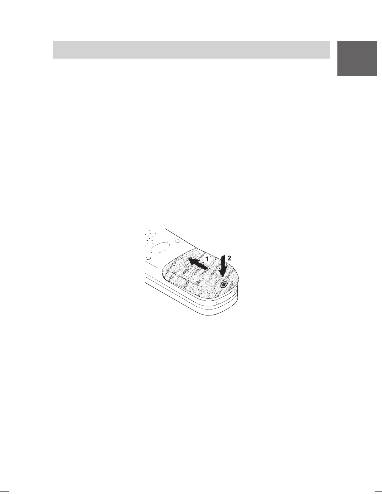
• Akku in das Gehäuse schieben (1)
• Akku an der Schraubenseite nach unten drücken bis er am Gehäuse
anliegt (2).
• Akku mit der Sicherungsschraube (Torx T10) befestigen (2). Das maxi-
male Anzugsmoment der Schraube beträgt 60 Ncm. Wir empfehlen den
Schraubendreher mit der Artikelnummer 50 1010 5300. Dieser Schraubendreher ist auch im 5er Pack erhältlich unter der Artikelnummer
50 1010 5400.
D
Ladegerät FC1 S Ex mit der Artikelnummer 50 1018 1001 aufstellen
(nur außerhalb explosionsgefährdeter Bereiche)
S tellen Sie das Ladegerät auf eine feste, ebene Unterlage, z. B. auf einen
Tisch. Wählen Sie einen Standplatz außerhalb explosionsgefährdeter
Bereiche, der vor direkter Sonneneinstrahlung und Feuchtigkeit geschützt ist.
• Stecken Sie das Steckernetzteil in eine Steckdose.
• Stecken Sie den kleinen Stecker der Anschlussschnur in die Buchse auf
der Rückseite des Ladegerätes. Hinweis: Das Business Handset FC 1
und das Handset FC1 Ex unterscheiden sich in den Gehäusemaßen und
haben daher unterschiedliche Ladegeräte.
Das Ladegerät ist nun betriebsbereit.
V 3.5 • 05/2005
41
Page 42

D
Mobility Server I 33 / CS I55 • I 1/3/5
FC1 Ex (HS) – Inbetriebnahme
Handset FC1 Ex aufladen
Stellen Sie das Handset FC1 Ex in das Ladegerät. Sie hören einen Bestätigungston.
Das Handset bleibt ein- oder ausgeschaltet, entsprechend dem Zustand, in
dem es vor der Ablage im Ladegerät war.
Das Akku-Symbol in der Symbolzeile bewegt sich, bis der Akku voll geladen
ist. Während des Aufladens werden die Akkus leicht warm. Das ist normal.
Sobald der Akku voll ist, beginnt die Erhaltungsladung. Sie wird durch einen
blinkenden Rahmen des Akku-Voll-Symbols angezeigt.
Zusatzakku aufladen
An der Rückseite des Tischladegerätes FC1 S Ex befindet sich eine offene
Bucht für das Laden eines Reserve-Akkus. Legen Sie einen Akku mit den
Kontaktflächen nach unten und der Bohrung für die Sicherungsschraube
nach außen in die Ladebucht und drücken Sie ihn sanft nach unten gegen
die Kontaktfedern der Ladebucht. Sobald der Kontakt hergestellt ist und
der Ladevorgang beginnt, wechselt die Farbe der Leuchtdiode vorn unten
am Tischladegerät von grün nach rot.
Hinweise zum Akkugebrauch
Stellen Sie das Handset FC1 Ex nach jedem Einsetzen eines Akkus für
mindestens 14 Stunden in das Ladegerät um den Akku vollständig
aufzuladen. Stellen Sie das Handset in der ersten Betriebswoche nach
Einsatzende in das Ladegerät. Neue Akkus erreichen ihre volle Kapazität
in der Regel erst nach einigen Tagen normalen Gebrauchs.
Sie können Ihr Handset nach Einsatzende, über Nacht und am Wochenende im Ladegerät stehen lassen. Der Akku kann nicht überladen werden.
Lassen Sie den Akku nicht in der prallen Sonne liegen. Er dankt es Ihnen
mit einer langen Lebensdauer.
42
Page 43

Mobility Server I 33 / CS I55 • I 1/3/5
FC1 Ex (HS) – Technische Daten / Zubehör
Handset FC1 Ex / FC1 Ex HS (explosionsgeschützte Ausführungen)
D
Standard: DECT
TM
(Digital Enhanced
Cordless Telecommunications)
Maße: 141 mm x 47 mm x 25 mm (plus Klipp)
Gewicht, Handset: ca. 140 g (mit Akku)
Akkutyp: NiMH; 650 mAh
Betriebsdauer Handset Sprechen: 7 Stunden
(mit vollem Akku): Stand-by: 70 Stunden
Ladezeit: ca. 5 Stunden
Frequenzbereich: 1,88 GHz ... 1,9 GHz
Sendeleistung: Mittelwert: 10 mW; Spitzenwert: 250 mW
Zulässige Handset: – 10 °C bis + 55 °C
Betriebstemperatur: Ladegerät: + 5 °C bis + 40 °C
Lagertemperatur: – 25 °C bis + 55 °C (Kurzzeitlagerung,
maximal 1 Monat)
0 °C bis + 35 °C (Langzeitlagerung)
Transporttemperatur: – 20 °C bis + 60 °C
Ruftonlautstärke 1: maximal 81 dB SPL in 30 cm Entfernung von
der Schallquelle
Notruf-Signalisierungs- 79 dB SPL in 30 cm Entfernung von
Lautstärke 1: der Schallquelle
Schutzart 2 für FC1 Ex: IP 65 (staubdicht und strahlwassergeschützt)
Schutzart 3 für FC1 Ex HS: IP 54 (staub- und spritzwassergeschützt);
!
SPL ist der unbewertete Sound Pressure Level.
2
Die Schutzart IP 65 gilt nur mit eingeklebtem Original-Dichtungsstöpsel.
Der Betrieb des Handsets mit einer Hör-/Sprechgarnitur ist unzulässig!
3
Die Schutzart IP 54 gilt nur, so lange die Anschlussbuchse für die Hör-/
Sprechgarnitur durch den Original-Dichtungsstöpsel verschlossen ist!
Achtung: Wird dieses Handset ohne Hör-/Sprechgarnitur betrieben,
muss die Anschlussbuchse mit dem Originalstöpsel verschlossen sein.
Anderenfalls erlischt die Ex-Betriebserlaubnis.
V 3.5 • 05/2005
43
Page 44

D
Mobility Server I 33 / CS I55 • I 1/3/5
FC1 Ex (HS) – Technische Daten / Zubehör
Zubehör 1: Ladegerät FC1 S Ex, Art.-Nr. 50 1018 1001
Steckernetzgerät für Europa
Steckernetzgerät für Großbritannien
Wechselakku
Tragetasche
MEM-Card-Manager
Hör-/Sprechgarnitur (Art.-Nr. 50 1010 5101)
für das FC1 Ex HS
1
Einige Teile des Zubehörs müssen gesondert bestellt werden.
44
V 3.4 • 04/2004
Page 45

Mobility Server I 33 / CS I55 • I 1/3/5
Important Information
Contents of the operating instructions
These operating instructions explain how to start using your handset. They
describe all the basic operating rules and the most frequently used
functions and settings.
A comprehensive description of all the system-specific functions can be
found on the CD-ROM supplied. You can view and print out the operating
instructions.
Product package (set)
Please check the contents of your FC1 product package immediately:
• Business Handset FC1 with hint s on operation.
When delivered ex works, explosion-proof FC1 Ex units have a clip attached
which must not be removed! An exception is specified in section safety
instructions, use of bag, explosion-proof units with and without a clip.
GB
• MEM-Card
• Changeable battery pack. Explosion-proof units may only be operated
with the explosion-proof battery part no. 50 1014 8000.
• Charger. Explosion-proof units may only be charged with the FC1 S Ex
charger, part no. 50 1018 1001.
• Plug-in mains unit
• These Short Operating Instructions
• CD-ROM with detailed operating instructions
All these components of the product package may be obtained separately.
Where you can use your business handset
The FC1 business handset is suitable for use in the office, outdoors or in a
dusty environment. It complies with protection class IP 54 and is splashproof and dust-protected.
Protecting against hearing damage
Keep the handsfree loudspeaker on the rear side of the handset away
from your ears!
The signal tone’s level of more than 80 dB (A) may cause severe damage
to your ears. In particular this damage impends if the distance between the
handsfree loudspeaker and your ears is too low or if your ears will be
exposed to a signal of this strength frequently.
V 3.5 • 05/2005
45
Page 46

GB
Mobility Server I 33 / CS I55 • I 1/3/5
Important Information
Operating the rechargeable battery pack
• Rechargeable batteries must be used in the appropriate manner. Funktel
is not liable for damage which occurs due to inappropriate handling of
the battery pack. Follow the Notes on the rechargeable battery pack on
page 53, please!
• If batteries leak in extreme cases, you must reckon with escaping
electrolyte or gases. Put the unit out of operation and return it to the
after-sales service. Whitish deposits on the housing or on the battery as
well as unusual or pungent smells indicate leaks.
• Protect yourself against cauterisations and poisoning by avoiding to
inhale escaping gases and direct skin contact with leaking batteries. If in
doubt, consult a doctor!
• Remove the batteries from the unit prior to dispatch or storage during
extended periods in order to avoid deep discharge and damage.
• Do not throw the battery into a fire, it might explode.
• To avoid injury and fire damage, do not allow the contacts of the battery
to come into contact with conductive objects or to be short-circuited.
• Do not throw exhausted batteries into the dustbin! Take them to a
municipal collection centre or to your dealer where they can be disposed
of in an environmentally friendly manner. Please dispose of discharged
batteries only.
Caring for NiCd and NiMH battery packs
This section contains information on how to obtain optimum service life
from your battery pack. Use only system-compatible chargers for charging
the batteries!
1 Both discharged and charged battery packs without built-in electronics
can be stored during extended periods (up to several years) without
damage at a storage temperature of 0 °C to 35 °C when separated from
the units. Charged batteries discharge themselves within a few weeks or
months. This self-discharge is harmless since this is no deep discharge.
2 Battery packs with built-in electronics (e.g. protective circuit for realizing
the explosion protection in explosion-proof battery packs) discharge
themselves completely after some time due to the current consumption
of the built-in electronics even when disconnected from the unit and will
be permanently damaged by this deep discharge. To avoid this noxious
46
V 3.5 • 05/2005
Page 47

Mobility Server I 33 / CS I55 • I 1/3/5
Important Information
deep discharge during extended storage periods, charge such battery
packs once before storing them and then regularly every 3 months. The
allowed storage temperature for extended storage is also between 0 °C
and 35 °C.
3 Always charge new or stored battery packs without any interruption
before using them. The same applies to battery packs of an unknown
charge degree. The recommended charging times can be taken from the
Operating Manual.
4 If you detect that new battery packs or packs that have been stored for
an extended period considerably fall below the service time stated in
your Operating Manual of your unit following the first charging (item 3),
please apply the battery pack cure described in item 8.
5 Charge discharged batteries without delay. Or at least separate them
from the unit. This avoids deep discharge of the battery packs However, pay attention to the particularities regarding the storage of
battery packs with built-in electronics as mentioned above in item 2!
GB
Discharged battery packs can be identified by the "battery-low" indication
or by the failing unit function.
6 Ensure that the battery pack is not permanently 100% charged. For the
battery-powered unit, this means: Do not put it back into the charger
immediately after a few or short uses, but leave it in stand-by mode for
an extended time, e.g. overnight next to the charger, if possible until the
"battery-low" indication appears on the unit. Regular and complete
discharging and charging of the battery pack avoids early capacity
losses of the cells.
7 Do not constantly change half-charged or even almost fully charged
battery packs. When operational reasons request changing the battery
pack, you should extend the change intervals so that the battery pack is
discharged to the greatest possible extent before it is replaced, but
without endangering safe unit function due to a discharged battery
(provide a operational standby period!).
8 If the service times of the unit are considerably shorter after extended
use of the unit, try the battery pack cure:
Discharging: Use the unit (handset) until the "battery-low" indication
appears.
Charging: Charge the battery pack as described in the Operating Manual.
V 3.5 • 05/2005
47
Page 48

Mobility Server I 33 / CS I55 • I 1/3/5
Important Information
Repeat this cycle (discharging, charging) several times.
With each pass, the battery pack regains a part of its initial capacity.
9 Harmful influences regarding the battery pack service life and outside of
Funktel's control include:
Extremely low and high temperatures during storage and operation,
GB
Permanent charging in the charger,
Deep discharge in the unit or while storing.
Handling battery chargers
• All two-pole-and-earth socket outlets for the plug-in power supply units
must be located near the chargers to be connected and must be
accessible at all times. The two-pole-and-earth socket outlets must have
been properly installed by qualified personnel.
Before plugging the power supply unit into the socket outlet: Make sure
that the available mains voltage matches the voltage indicated on the
plug-in power supply unit (e.g. 230 V, 50 Hz).
• Chargers and plug-in power supply units do not contain any user-
serviceable parts. Repairs must be carried out properly by qualified
personnel. Have defective or damaged chargers / power supply units
replaced by genuine spare parts only, even if only the cord is damaged.
• Warning – Handling of damaged power supply units!
Disconnect the socket outlet from the supply (remove or disable fuse of
corresponding circuit) before removing a mechanically damaged plug-in
power supply unit from the socket outlet!
Touching live parts is dangerous to life!
• The chargers are designed for use in an office-like environment. Protect
them against heavy soiling, dust, moisture, wetness and direct heat
radiation.
Protecting the handset against manipulation and environmental
impact
• Never unscrew the handset housing! The housing could be damaged as
a result. It does not contain any components that can be repaired by
yourself.
48
V 3.5 • 05/2005
Page 49

Mobility Server I 33 / CS I55 • I 1/3/5
Important Information
• Protect the unit against extreme environmental influences (e.g.
temperatures outside those specified in the technical specifications and
extended direct solar radiation)!
• Do not expose the unit to extremely strong magnetic fields, e.g. near
induction-type furnaces and electric welding equipment!
Protecting electronic units against interference
Other electronic units are generally protected against high-frequency
irradiation. However , if a device of this kind is insufficiently protected,
malfunctions may occur . These malfunctions can be eliminated by increasing
the distance between the units concerned.
Tips for location
You are advised to use an antiskid surface for your charger, in particular
with new furniture or furniture that has been treated with preservation
agents. Varnishes or varnish preservation agents may contain substances
that soften the feet of the device, thus leaving unsightly stains on the
surface of your furniture. Funktel cannot be made liable for such damage.
General approval and EU conformity
The Funktel GmbH declares that the product FC1 concurs with the basic
requirements and other relevant provisions of EU guideline 1999/5/EU
(R&TTE).
This device is suitable for connection to the radio interfaces (DECT
TM
) of
Funktel Mobility Server and fulfils the basic requirements laid out in EU
Guideline 1999/5/EU (Radio and Telecommunication Terminal Equipment,
R&TTE).
GB
Due to its construction, this device is not suitable for direct operation on
interfaces to public telecommunications networks.
In the unlikely event of any problems during operation, please contact your
dealer or the Funktel Service organisation.
The declaration of conformity can be ordered via the e-mail address
[email protected].
This device operates in accordance with the DECT
DECT
TM
is a registered trademark of ETSI
TM
system with a
49
Page 50
Mobility Server I 33 / CS I55 • I 1/3/5
Important Information
frequency range of 1880 MHz to 1900 MHz. The allocation of this
frequency range in the frequency utilisation plan is initially valid until 2008
and will be extended in accordance with European harmonisation.
approval and EC prototype test certificate for explosion-proof
units
GB
For gas explosion protection according to ATEX, the EC prototype test
certificate TÜV 03 ATEX 2244 X with the identifier
II 2 G EEx e ib IIC T4
applies for an ambient temperature range Ta of - 10 °C to + 55 °C.
For dust explosion protection according to ATEX, the EC prototype test
certificate IBExU03ATEX1216 X with the identifier
II 2 D IP 65 T 80 °C
applies for an ambient temperature range Ta of - 10 °C to + 55 °C.
DECT
TM
is a registered trademark of ETSI
50
Page 51

Mobility Server I 33 / CS I55 • I 1/3/5
Commissioning
If your business handset is not yet assembled completely
If the business handset is not completely assembled when you receive it,
you must
• Insert the MEM-Card (see page 52),
• Install the rechargeable battery pack (see page 52) and
• Remove the protective film from the display, if necessary.
• Finally your service team must register the business handset with your
telephone system.
Your business handset is then ready for operation.
• Now connect the charger (see page 53).
If your business handset is already fully assembled
If the business handset is already completely assembled and registered
with your telephone system when you receive it, you only need to connect
the charger (see page 53).
MEM-Card
You can only use your business handset to make and receive telephone
calls if a MEM-Card is inserted. It performs the memory function for your
important business handset data, as well as your personal settings and
your telephone book.
GB
If you switch handsets you can remove the MEM-card from the ancient
one and insert it into the new one. Thus, you can use the MEM-Card
together with the new handset to make and receive telephone calls
immediately.
Attention!
Read and follow the safety instructions about the handling of
explosion-proof units from page 76 to 79.
51
Page 52
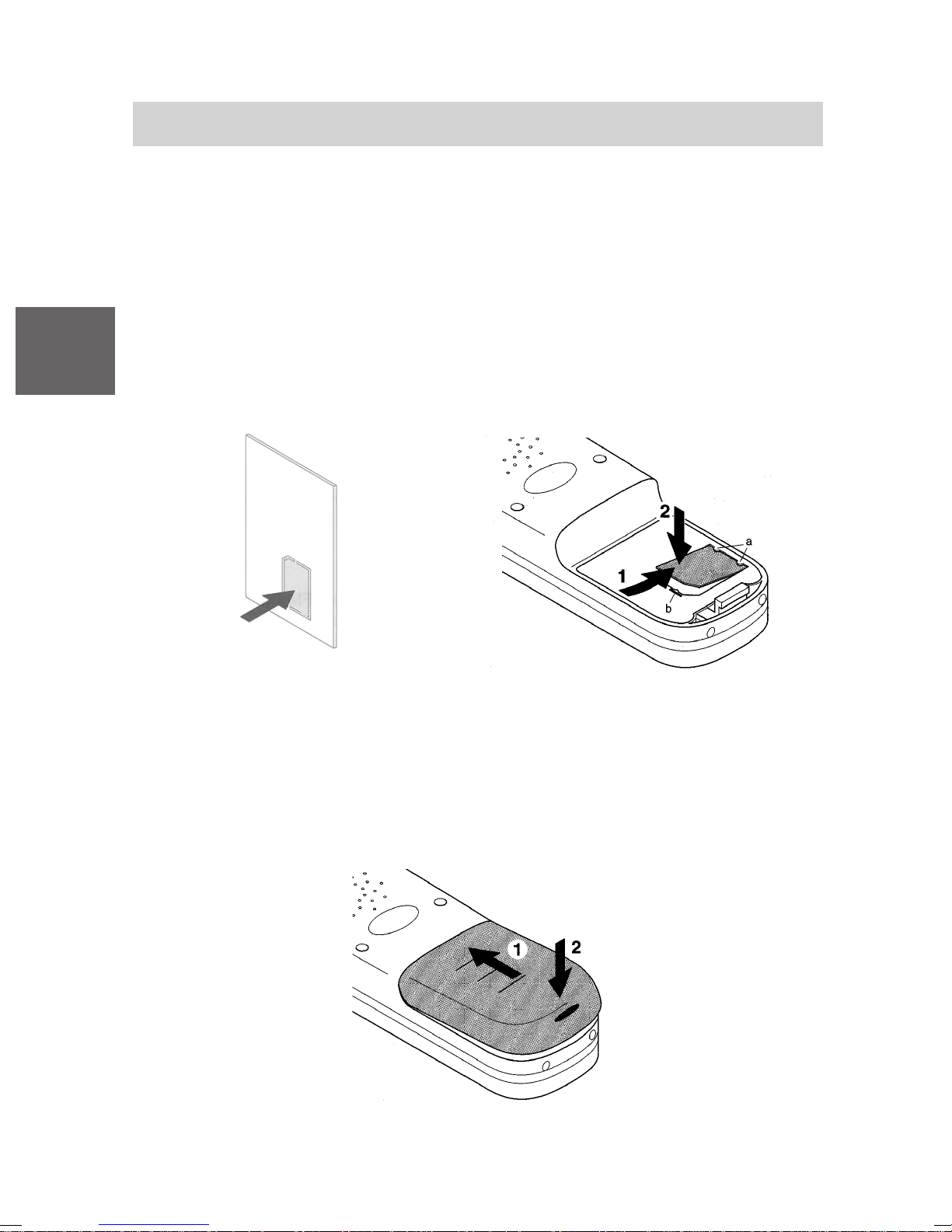
GB
Mobility Server I 33 / CS I55 • I 1/3/5
Commissioning
Inserting the MEM-Card
• First use your fingers to press the small MEM-Card out of the larger
frame (next illustration on the left).
• With the short edge at an angle under the holding crescents a, push the
MEM-Card into the MEM-Card compartment (next illustration on the
right) (1). The golden contact surface of the MEM-Card must face
downwards!
• Press the MEM-Card downwards until the small tag b locks
Inserting the rechargeable battery pack
• Push the battery pack into the casing (1).
• Press the battery pack downwards on the lever side until you hear it lock
(2).
(2).
52
Page 53
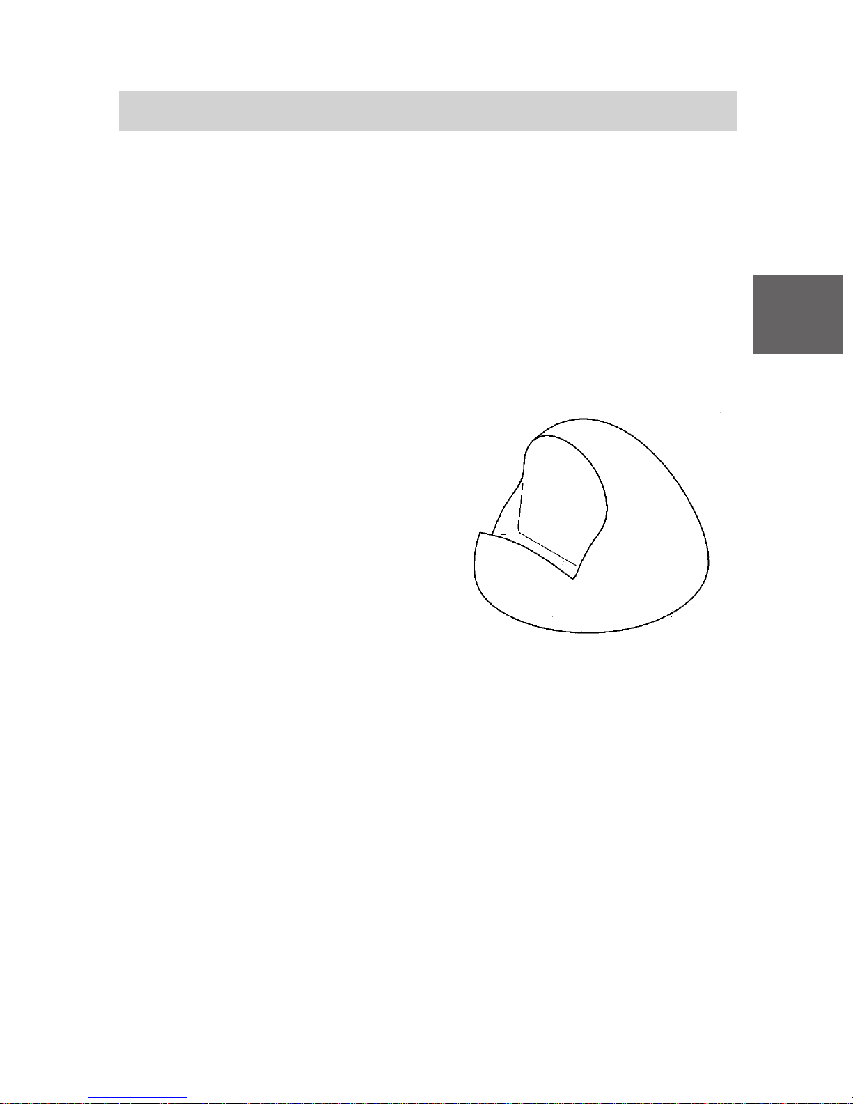
Mobility Server I 33 / CS I55 • I 1/3/5
Commissioning
Placement of the charger
Place the charger on a solid, even surface, e.g. a table. Choose a location
that is protected from direct sunlight and dampness.
• Plug the plug-in mains unit into a socket.
• Insert the small connecting cord plug into the back of the charging
device. Note: Chargers of type Charger Plus must be operated using
Plug-in mains unit Plus only!
The charger is ready for operation now.
Charging the business handset
Simply place the business handset into
the charger . You will hear an
acknowledgement tone. The display
light will switch on briefly.
GB
The business handset remains
switched on or off, depending on its
status before it was placed in the
charger.
The battery symbol in the symbol row
moves until the battery is completely
charged. When the batteries are being
charged, they will become slightly
warm. This is perfectly normal.
Notes on the rechargeable battery pack
Every time you insert a battery pack into your handset, you must charge
the battery to full capacity for at least 14 hours. Then during the first
week of operation, always return the business handset to the charger
cradle. New batteries will in general reach full capacity only after several
days of normal use.
You can leave your business handset in the charger cradle for extended
periods. The battery cannot be over-charged.
Charger
Do not leave the battery in direct sunlight. Proper care of the battery is
rewarded with a long service life.
53
Page 54
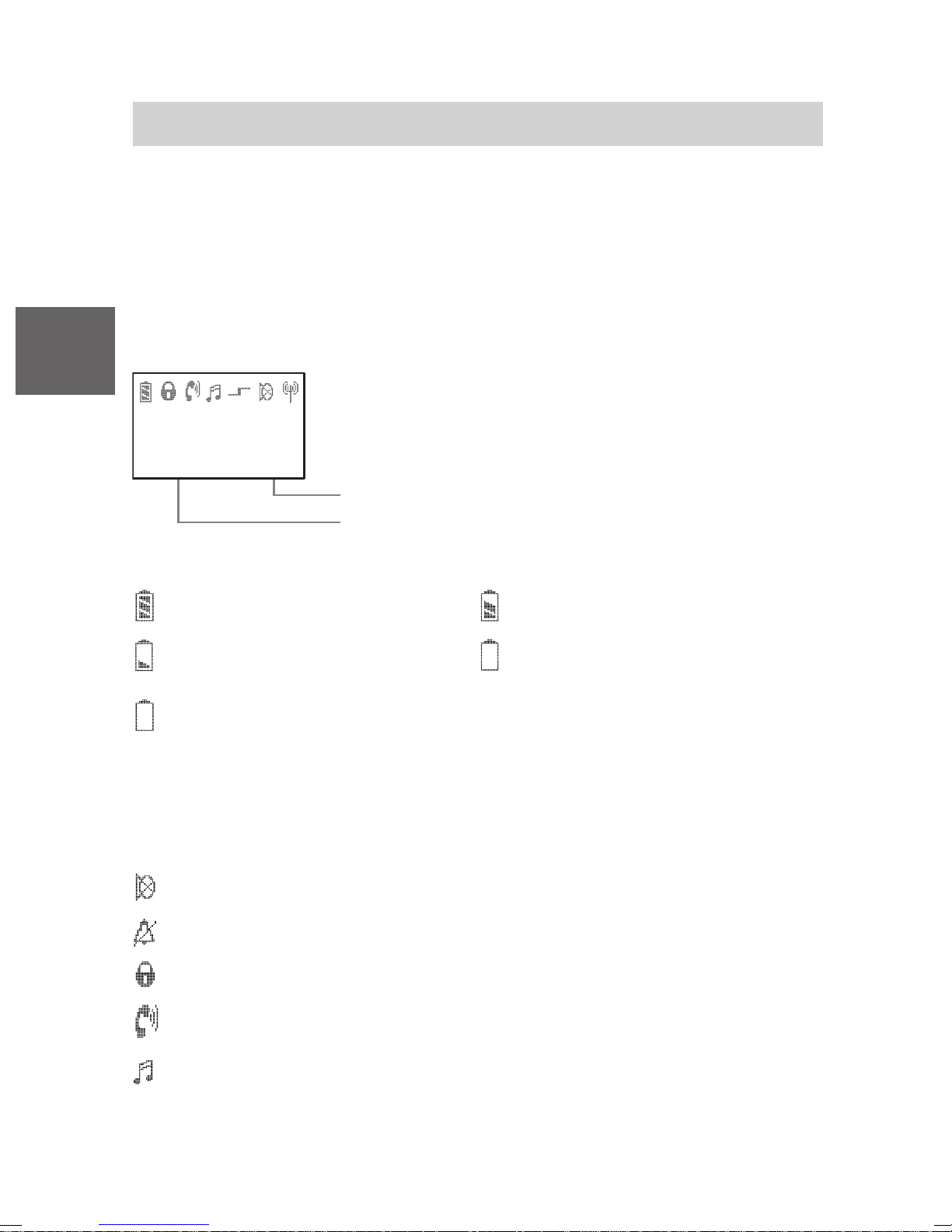
Mobility Server I 33 / CS I55 • I 1/3/5
Display
Texts and symbols in the display assist you in operating the business
handset. They will guide you through the menus and give you information
on the status of your handset.
The functions of the right and left softkeys change according to the current
status. The respective functions are shown in the display directly above
the softkeys.
GB
The lines in the display
J o h n P u b l i c
2 7 3 4
C l r d o w n M e n u
Symbol denotations
Battery completely charged, Battery nearly charged,
Battery nearly empty, Battery empty.
Battery symbol flashing: Capacity for less than five minutes!
Please note: After having inserted a battery pack, the business
handset does not “know” its charging status. So no battery signal is
shown. The battery signal in the display will only appear after the
battery pack has been charged for at least 14 hours without any
interruption in the business handset using the charger.
Symbol line indicating the status of the telephone.
Two text lines e. g. for the name and call number.
Function of the right softkey e. g. Menu
Function of the left softkey e. g. Cleardown
Mute: The microphone is off. Your call partner cannot hear you.
No calling signal: Calling signal is set to mute.
Lock: The business handset is locked.
Handset: The business handset has a telephone connection.
Dual-tone multifrequency dialling: Each push of the button is
transmitted to the connection subscriber as a DTMF tone, with audible
output (DTMF post dialling).
54
Page 55
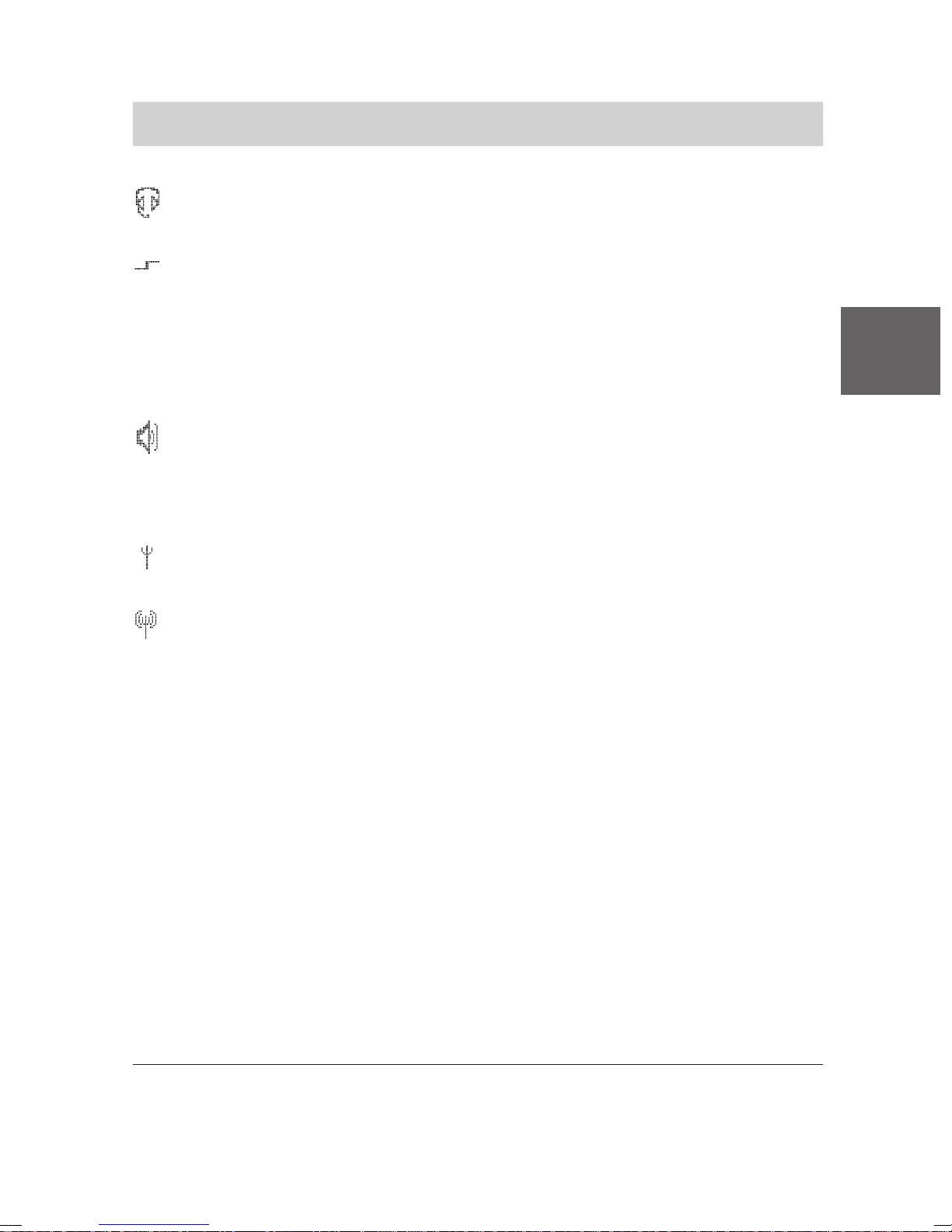
Mobility Server I 33 / CS I55 • I 1/3/5
Display
Headset: You are telephoning using the headset. The housing
microphone and loudspeaker are switched off automatically.
Special function1 activated: Star key was pressed for a long time
while you were executing a text input e. g. entering a name to the
local telephone directory. Pushing the star key toggels between
capitals and lower case letters ... or
S t ar key was pressed for a long time (until a deep confirmation tone
sounds) in order to initiate locking or unlocking the keyboard.
Loudspeaker: The loudspeaker for handsfree operation on the rear
side of the housing is switched on.
Keep the handsfree loudspeaker on the rear side of the handset
away from your ears! See the warning on page 45.
GB
Within range of the system: Your business handset is within range
of a base station. You can make and receive telephone calls.
Connection to system: Your business handset has a radio link.
LIST
There is an entry in the call list, you did not yet take note of.
MAIL
There is at least one unread message in the message list.
mail
There is at least one read (known) entry in the message list.
mail, LIST
There are known entries in the message list and at least one entry in
the call list you are not yet aware of.
MAIL, LIST
There are at least one unread entry in the message list and one
unread entry in the call list you are not yet aware of.
1
Presssing a key for a long time: Keep key depressed until a deep
confirmation tone sounds!
55
Page 56
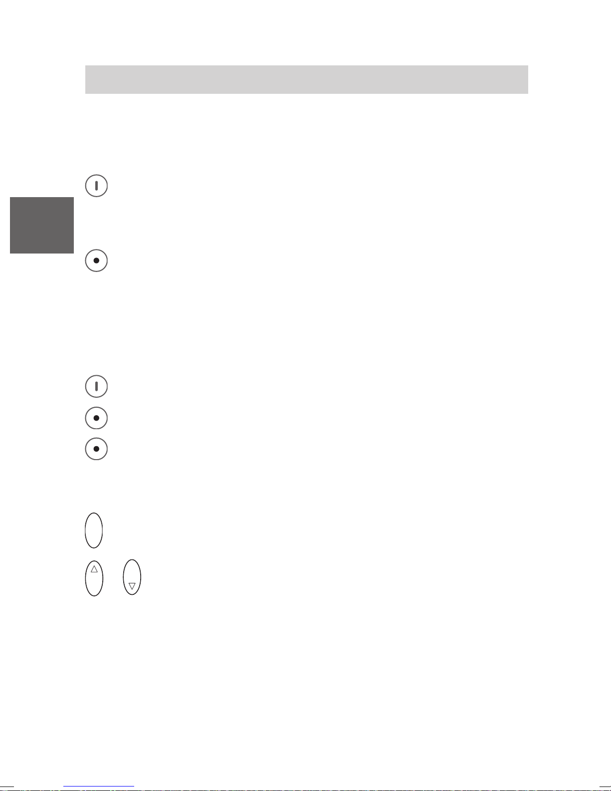
Mobility Server I 33 / CS I55 • I 1/3/5
Basic Rules of Operation
The operation of your handset includes several frequently-recurring
operating steps. Please familiarize yourself with these operating steps.
Switching on the business handset
The handset is switched off. Press the right softkey for a long
period.
GB
Switching off the business handset
The handset is in basic status. Press the left softkey for a long
period.
Left and right softkeys
The function of the softkeys changes according to the situation. The
respective function always appears in the display above the softkey, e. g.
Menu or Clrdown.
The right softkey is used for switching on or to call up menus.
The left softkey is used for ending a menu option or cancelling.
If you press the left key for a long period when in any of the menus,
the business handset will be returned to its basic status.
Selector
O K
O K
This concludes the setting procedure.
O K
or
Press upon the upper or lower end (arrow) of the selector to
scroll through the menus or through the call list or message list.
Doubly occupied keys
Some keys on your business handset are occupied by two functions. The
additional blue labels denote these keys. You must hold the key for longer
if you want to trigger the second blue function. You will hear a low
acknowledgement tone.
56
Page 57
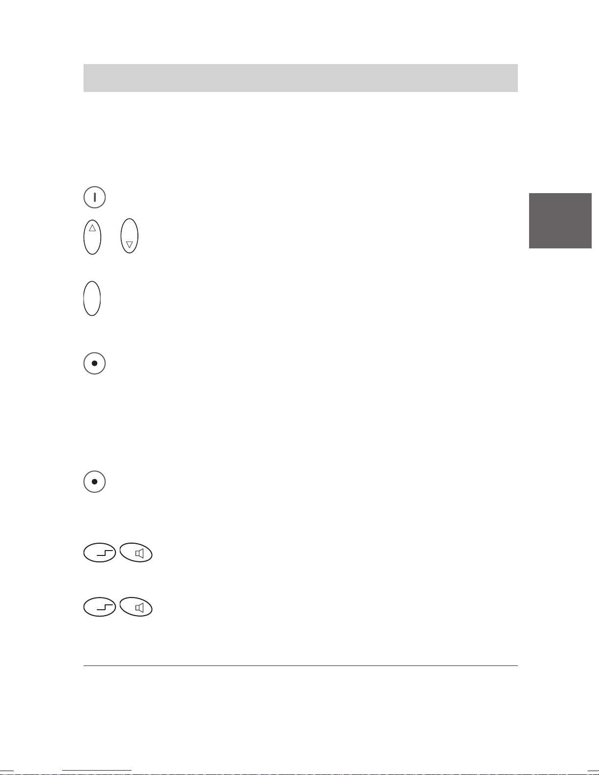
Mobility Server I 33 / CS I55 • I 1/3/5
Basic Rules of Operation
Selecting a menü
Some functions and settings of your handset can be obtained via the
display contents (menu). The menu is set out in such a way that most of
the menu options lead to submenus.
Call up the menu 1 using the right softkey.
O K
O K
or
Press upon the upper or lower end (arrow) of the selector to
mark the desired menu option, e.g. System.
GB
O K
Press upon the centre of the selectors, to select the menu point.
Returning to another menu level
The left softkey enables you to move to the next menu level up or
leave the menu.
Submenus
Submenus are operated in exactly the same way as the main menu.
Cancel
Press the left softkey for a long period in order to reach basic
status.
Keyboard lock using the keys
R
Ü
Lock: Press the star key long, followed by R key.
Unlocking the keyboard
R
Ü
1
In the basic status, you can also call up the menu by pressing the lower
Unlock: Press the star key long, followed by R key.
end (arrow) of the selector.
57
Page 58
GB
Mobility Server I 33 / CS I55 • I 1/3/5
Basic Rules of Operation
Temporarily adjusting the business handset volume during
conversation
The basic adjustment
section Setting the business handset to change the long-lasting settings.
You may temporarily change these settings during a telephone
conversation:
You are speaking on the handset with handsfree loudspeaker off or
on.
Temporarily increasing the business handset volume
1
varies from level 1 (low) to level 6 (loud). See
O K
Keep the upper part of the selector depressed for a long time until a
deep confirmation beep sounds. The volume steps up one step.
Repeat the procedure until the volume reaches an appropriate level.
Temporarily decreasing the business handset volume
O K
Keep the lower part of the selector depressed for a long time until a
deep confirmation beep sounds. The volume steps down one step.
Repeat the procedure until the volume reaches an appropriate level.
This adjustment retains for the actual telephone conversation only. For the
next phone call the volume for business handset and for handsfree
loudspeaker automatically will switch back to the original long-lasting
settings.
1
The variable basic adjustment of the business handset volume has no
effect on the basic volume adjustment of the handsfree loudspeaker.
58
Page 59
Mobility Server I 33 / CS I55 • I 1/3/5
7
P Q R S
Telephoning As Usual
You may use your business handset to telephone in the usual manner.
Telephoning within the telephone system (internally): Dial the internal call
number required.
External Calls: Dial the external line code (usually zero), followed by the
call number of your call partner.
Making a call
Lift the business handset (going off-hook).
GB
A B C
1
2
Ending a call
Replace the business handset (going on-hook).
Redialling
1
Lift the handset.
#
Press the hash key for a long period.
Accepting a call
Your business handset rings.
Lift the handset.
M N O
Dial the call number, e. g. 1276.
6
Note:
When you receive a message, an existing call will not be interrupted. See
Messaging section.
1
If you are operating a Mobility Server I 1/3/5, you can only use the redial
function for external calls.
V 3.5 • 05/2005
59
Page 60
GB
Mobility Server I 33 / CS I55 • I 1/3/5
Refer-Back Call And Call Forwarding
During a telephone conversation, you may go into consultation and speak
to another call partner. Your initial call partner is left waiting. – It is also
possible to transfer the caller.
Activating a refer-back call
You are speaking on the handset.
R
Activate a refer-back call. Your call partner cannot hear you.
P Q R S
7
M N O
6
J K L
5
G H I
Enter the desired number, e .g. 7654.
4
The number 7654 appears in the display. The connection is made.
Your initial call partner is left waiting.
Ending a refer-back call
R
Return to your initial call partner 1 by pressing the R key.
Forwarding a caller
You are speaking on the handset.
R
7
Activate a refer-back call.
P Q R S
M N O
6
J K L
5
G H I
4
Enter the desired number, e .g. 7654.
Replace the business handset (going on-hook) 2.
1
On the Mobility Server I 1/3/5, the connection to the refer-back extension
will be broken when you end the refer-back call.
2
You may still forward the caller if the third party’s number is engaged.
60
Page 61
Mobility Server I 33 / CS I55 • I 1/3/5
Handsfree Operation, Switch Off the Microphone
You can switch on the loudspeaker installed for handsfree operation. You can
then hear your caller’s amplified voice and you can speak with him or her.
You may switch off the microphone on your business handset whilst
telephoning. The business handset remains switched on. Your call partner
cannot hear you, but you can hear him.
Switching on the loudspeaker for handsfree operation
You are speaking on the handset.
GB
R
To switch on the handsfree loudspeaker: Press R key for a long
period.
appears in the display.
Switching off the handsfree loudspeaker
You are speaking on the handset. The conversation will be amplified
by the handsfree loudspeaker.
R
To switch off the loudspeaker: Press R key for a long period.
appears in the display.
Switching off the microphone (mute)
You are speaking on the handset.
1
To switch off microphone: Press key 1 for a long period. appears
in the display.
Reactivating the microphone
1
1
again
The microphone is switched off. is lit in the display.
1
To switch on microphone: Press key 1 for a long period. Y ou may
continue telephoning now.
1
At the end of the call, the handsfree loudspeaker will be switched off
automatically and the microphone will be switched on again automatically.
If you place your business handset in the charger during a call,
handsfree operation will be switched on automatically.
61
Page 62
GB
Mobility Server I 33 / CS I55 • I 1/3/5
Setting the Business Handset
You may make the business handset settings when in basic status.
Ringing signal
O K
Menu Set telephone.
O K
O K
Menu Ringing signal.
O K
O K
Confirm.
Make the desired ringing setting, e. g. Ringing tone. You may
choose: ringing tone, vibrating
O K
Confirm.
Ringing tone volume
O K
Menu Set telephone.
O K
O K
Menu ringing tone volume.
O K
Confirm.
1
, both, short ringing tone and mute 2.
D E F
3
O K
1
Enter the secury handset ringing tone volume (from 1 to 9), e. g. 6.
Confirm.
The business handset will not vibrate in the charger. When you have
selected vibration as the calling signal, the ringing tone will sound for a short
period
2
When a call is registered. If you have selected mute as the call signal,
the corresponding symbol
62
appears in the display (see page 54).
Page 63
Mobility Server I 33 / CS I55 • I 1/3/5
Setting the Business Handset
Handset volume
O K
Menu Set telephone.
O K
O K
Menu handset volume.
GB
O K
3
O K
Confirm.
D E F
Enter the business handset volume (from 1 to 6), e. g. 3.
Confirm.
Determining the language of the local menu
O K
Menu Set telephone.
O K
O K
Menu Language.
O K
O K
Select a language, e. g. German.
O K
Confirm.
63
Page 64
GB
Mobility Server I 33 / CS I55 • I 1/3/5
Emergency Call
When your business handset is locked, only the function of the emergency
call number is ready for use. The display above the right softkey shows:
1
SOS
Emergency calls using the red emergency call button at the left side of
the top are always available – even if the handset is not locked.
Emergency calls during business handset locked may be released also
by pressing the right softkey twice.
Setting up and changing emergency call numbers
O K
.
O K
Menu Set telephone.
O K
Menu Emergency No.
O K
2
O K
6
A B C
M N O
Confirm.
D E F
3
Confirm.
M N O
6
G H I
4
M N O
6
J K L
Enter the PIN, e. g. 2345.
5
M N O
Enter or change 2 the emergency call number,
6
e. g. 6666.
O K
Confirm.
Making an emergency call with the emergency call key
Press the emergency call button at the top for a long period. The
emergency call number is dialled.
1
The SOS emergency call is not available if an emergency call number has
not been entered; during a call; while a call or a message is being received;
or if the business handset is not within the range of the telephone system.
2
Deleting an emergency call number: Start change procedure as
shown above, delete the displayed emergency call number by pressing
the left softkey for a long period and confirm by pressing the selector.
64
Page 65

Messaging on Mobility Server I 33 / CS I55
Messaging
Messaging 1 enables you to send and receive brief messages with your
business handset.
You may send messages to individual subscribers and to groups. The call
number of a subscriber may vary from his telephone number in some
cases.
The messages are defined texts (fixed texts). The subsequent dialling of
any digits (figures) is permissible as needed. The list of fixed texts can be
obtained from your system administrator.
Verification for the sending party of the message:
The sender receives confirmation of the successful transmission of the
message, and of acknowledgement of receipt of the message by the
receiver, should this occur.
The latest 10 messages are stored in the message list. You may call back
the sender directly from the list.
GB
Note:
During reception of a message and during a possibly required manual
acknowledgement, an existing call connection is continued. Your
telephone partner can hear the signalling of the message.
Example:
User A and user B are holding a telephone conversation. User A receives a
message, announced by an acoustical signal.
The telephone connection persists during reception of the message and
during a possible manual acknowledgement from user A. The handset
microphone of user A remains switched on so that user B can hear what
happens at the site of user A.
The conversation can be continued after signalling and acknowledgement
are complete.
1
The messaging functions are available only on Mobility Server I 33 /
CS I55 with an additional Message Server connected.
The Message Server is a supplement to your private telephone system.
Refer to the header which contains the type of Mobility Server needed
for the functions described below.
V 3.5 • 05/2005
65
Page 66
GB
Messaging on Mobility Server I 33 / CS I55
Receiving a Message
Your business handset rings with a special ringing tone 1.
In the display appears the telephone number of the sender (where given)
and the message, e. g. 5371 Meeting in room 109.
While the message remains visible, you have the following options:
• Deactivate the ringing tone
R
Press the R button.
• Cancel the message in the display
Press the left softkey. The message goes to the message list. The
following appears in the idle display: mail.
• Delete the message totally
0
Press the 0 key.
or ...
Ü
Press the star key (long), then the left softkey.
• Manual confirmation
Important messages are preceded by an exclamation mark, e. g.
! Meeting. These messages must be manually confirmed.
• Manual confirmation, positive
A message with a preceding exclamation mark is in the display, e. g.
1
The ringing tone varies depending on the priority of the message.
66
Page 67
Messaging on Mobility Server I 33 / CS I55
Ü
Receiving a Message
! Meeting in room 109. You must confirm manually.
Press left softkey. +++OK appears in the display if the positive
confirmation was sent successfully.
• Manual confirmation, negative
A message with a preceding exclamation mark is in the display, e. g.
! Meeting in room 109. You must confirm manually.
GB
Ü
and then star (short) and star again (short). –––OK appears in the
display if the negative confirmation was sent successfully.
Ü
Press the star key (long), then the right softkey,
67
Page 68
Messaging on Mobility Server I 33 / CS I55
Message List and Call List
Message list
1
The 10 most recent messages are stored in the message list
memory). You may call back the sender from this list if the message was
sent from another handset. The word mail in the second display line
identifies a read mail list, the word MAIL (in capitals) indicates at least one
unread message. Make sure you keep an eye on that list!
(mail
GB
Call list
Unaccepted calls are stored in a call list
1
(list includes 10 most recent
calls). You may call back the calling person from this list. The word LIST
indicates at least one message which you are not yet aware of. When all
calls in the list have been looked at, the word LIST does not appear any
more. The 10 most recent calls remain stored in the call list unless they
are deleted manually.
Viewing the message list / call list or selecting it for evaluation
When the handset display is in basic status, it reads either MAIL LIST,
MAIL, LIST, mail LIST or mail.
Either press the key
O K
... press the top (upper arrow) of the SELECTOR key.
for a long period, or ...
0
When only one of the two lists contains entries, this list is opened
immediately. You may now scroll the entries of the opened list by
pressing the top (up) or the bottom (down) of the S
ELECTOR key
again. See next page!
When both lists contain entries, the display always shows the mail
list.
Now select the mail list or the call list by pressing the S
DOWN key again, then ...
1
Each entry in one of these lists contains the sender number, text, day
and time and the number of calls or delivery attempts. In case of several
calls or delivery attempts of the same message, the day and time data
always refer to the most recent attempt.
68
ELECTOR UP /
Page 69
Messaging on Mobility Server I 33 / CS I55
Message List and Call List
O K
Confirm the selected list by depressing the centre of the SELECTOR
key in order to open it.
Scrolling in a called up list
or
O K
To scroll, press the top (up) or the bottom (down) of the SELECTOR
O K
key. The display e.g. reads: 6789 Conference 15.05.12:26.
If the message is longer than one line
If the message is longer than 16 characters, it is shown for the moment in
abbreviated form in line 1 of the display. You may have the unit show you
the message of up to 32 characters
#
Press the hash button for a long period. The rest of the message
1
.
appears in the second display line instead of the date.
Clearing a message or call from the list
GB
Call up and display the message or the call first, then ...
0
Press the 0 key.
or ...
Ü
Press the star key (long), followed by the left softkey.
Callback to the calling party from the call list ... or callback to the
sender of a message if the message comes from another handset
within the system
Display call or message, then ...
Pick up using the HOOK ON/OFF button and wait for the called person
to respond.
1
When the message is longer than 32 characters, it will be cut off after
character no. 31. The 32nd character is a dot which indicates that a part
of the message has been cut off.
69
Page 70
Messaging on Mobility Server I 33 / CS I55
Sending a Message
Send a defined text 1 (fixed text)
GB
Ü
Press the star key (long) and then the right softkey. The following
appears in the display: Mail-Adresse.
or
Press the right softkey for a long period. The following appears in the
display: Mail-Adresse.
then ...
A B C
1
Ü
7
2
Press the star button. 1234* appears in the display.
P Q R S
T U V
8
D E F
3
G H I
Enter the number, e. g. 1234.
4
Enter the number of the defined (fixed) text, e.g. 78.
1234*78 appears in the display.
Ü
Press the star button. The defined text appears in the display, e. g.
1234*Meeting in Room.
(You can use the left softkey
to make corrections, where necessary,
and to enter the number for a different fixed text.)
Press the hash (#) key. Message sent appears briefly in the display.
#
Verification
As described on page 71!
1
The defined texts (fixed texts) are stored centrally. A list of defined texts
can be obtained from your system administrator.
You may store the complete sending procedure for a message in the local
telephone directory, e. g.
, #, 1234, star , 78, st ar, star, 109, #. This is
useful for emergency calls, for example!
The key sequence
, # initiates messaging when calling up sending
procedure from telephone book.
70
Page 71
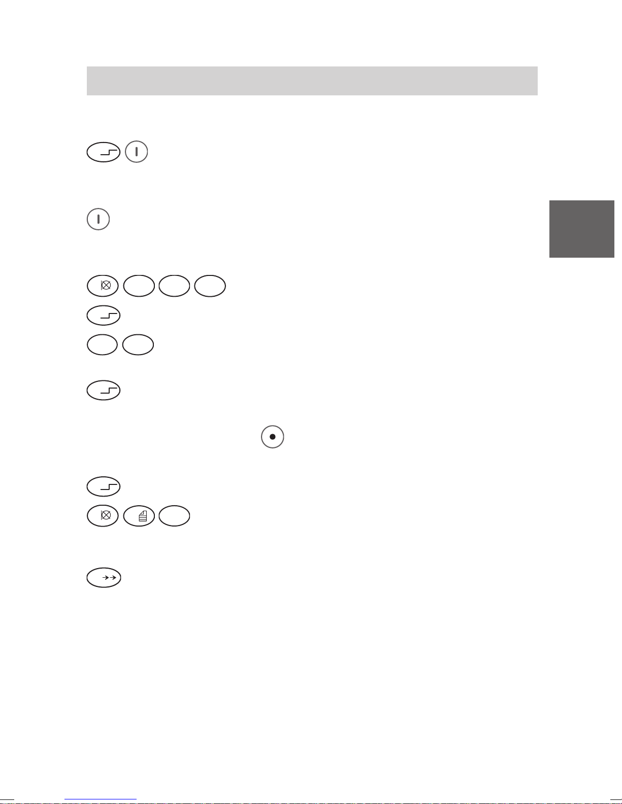
Messaging on Mobility Server I 33 / CS I55
Sending a Message
Send a defined text (fixed text) with postdialled digits
Ü
Press the star key (long) and then the right softkey. The following
appears in the display: Mail-Adresse.
or
Press the right softkey for a long period. The following appears in the
display: Mail-Adresse.
then
A B C
1
Ü
7
2
Press the star button. 1234* appears in the display.
P Q R S
T U V
8
D E F
3
G H I
Enter the number, e. g. 1234.
4
Enter the number of the defined (fixed) text, e.g. 78.
1234*78 appears in the display.
Ü
Press the star button. The defined text appears in the display, e. g.
1234*Meeting in Room.
(You can use the left softkey
to make corrections, where necessary,
GB
and to enter the number for a different fixed text.)
Ü
Press the star button.
1
0
W X Y Z
9
and dial digits where required, e. g. 109. In the display
appears the defined text followed by the postdialled figures, e. g.:
1234*Meeting in Room 109.
Press the hash (#) key. Message sent appears briefly in the display.
#
Verification
POS Meeting ... appears soon after successful transmission of the
message.
NEG Meeting ... appears in the display shortly afterwards if the
subscriber confirms negatively or is not reachable.
If the subscriber is not identifiable, or has not reacted at all to a message
requiring a manual confirmation, ??? Meeting ... appears in the
display shortly afterwards.
71
Page 72
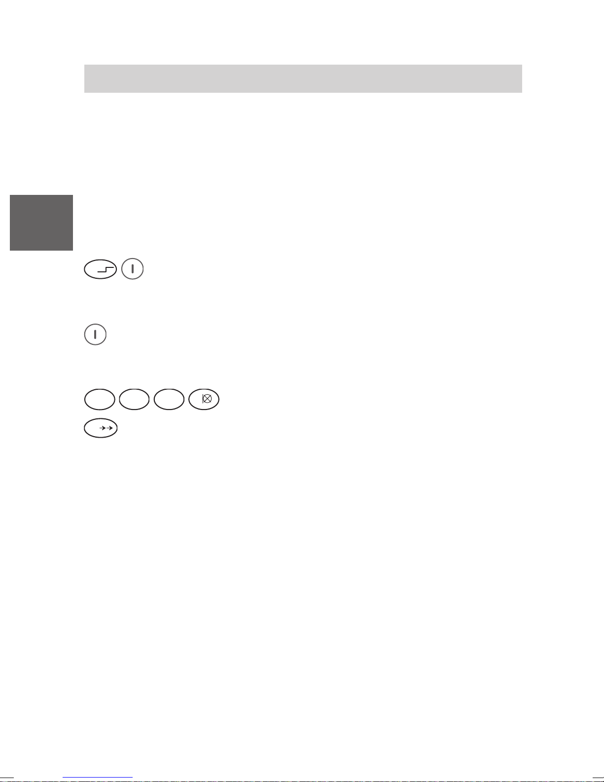
Messaging on Mobility Server I 33 / CS I55
Sending a Message
Sending a direct call
Sending a direct call means sending a call using a direct call number
which is linking one defined text (fixed text) to one defined receiver
(subscriber or group).
As an example the text for the direct call is assumed to be: Direct Call
Text.
GB
A list with the direct call numbers can be obtained from your system
administrator.
Ü
Press the star key (long), then the right softkey. The following
appears in the display: Mail adress.
or
Press the right softkey for a long period. The following appears in the
display: Mail-Adresse.
then
G H I
4
#
D E F
3
Press the hash (#) key.
A B C
2
Enter the direct call number, e. g. 4321.
1
Verification
POS Direct Call Text ... appears soon after successful
transmission of the message.
NEG Direct Call Text ... appears in the display shortly afterwards
if the subscriber confirms negatively or is not reachable.
If the subscriber is not identifiable, or has not reacted at all to a message
requiring a manual confirmation, ??? Direct Call Text ... appears
in the display shortly afterwards.
72
Page 73
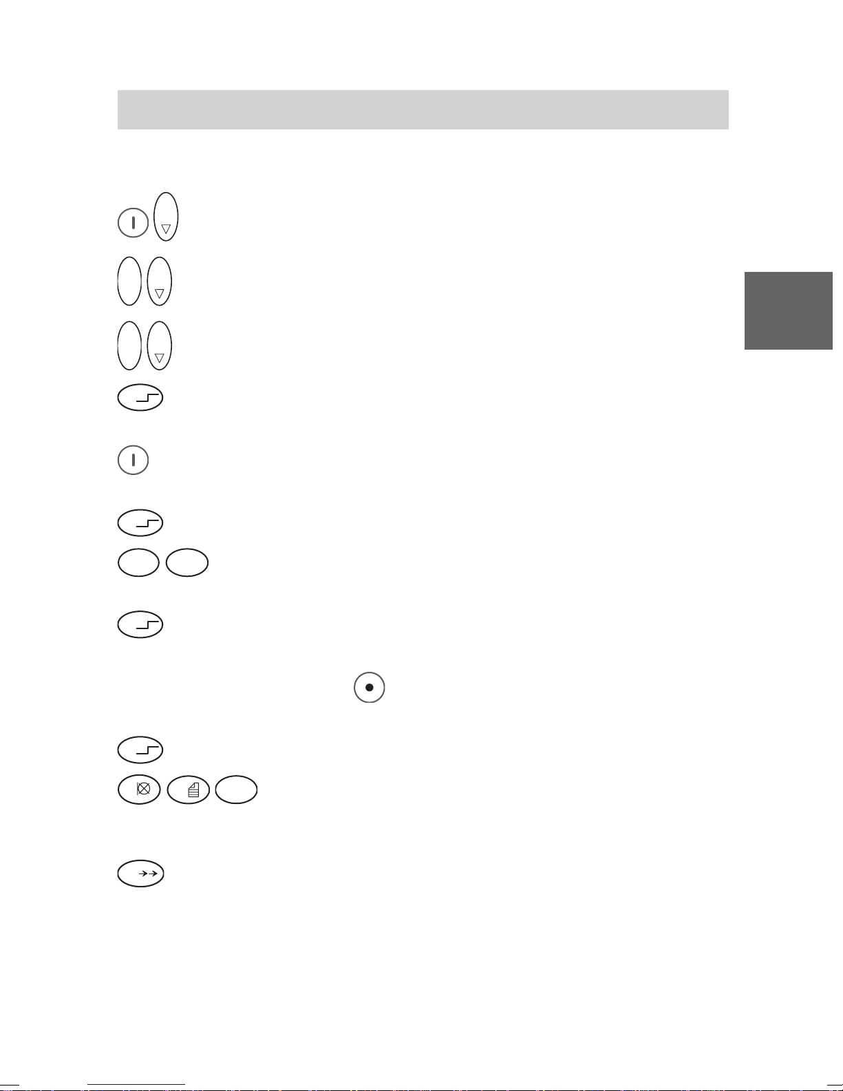
Messaging on Mobility Server I 33 / CS I55
Sending a Message
Send a defined text (fixed text) using the local telephone directory
O K
Menu Local tel. dir..
O K
O K
Menu Search.
O K
O K
Search for the entry, e. g. Jones.
GB
Ü
Press the star key for a longer period. The following appears in the
display assigned to the right softkey: Msg.to.
Press right softkey. The following appears in the display: 1234 Mail
adress.
Ü
7
Press star key. The following appears in the display: 1234*.
P Q R S
T U V
Enter the number of the defined text, e. g 78. 1234*78
8
appears in the display.
Ü
Press star key. The defined text appears in the display, e. g.
1234*Meeting in Room.
(You can use the left softkey
to make corrections, where necessary,
and to enter the number for a different fixed text.)
Ü
Press star key.
1
0
W X Y Z
and dial digits where required, e. g. 109. In the display
9
appears the defined text, followed by the postdialled figures, e. g.:
1234*Meeting in Room 109.
Press the hash (#) key. Message sent appears briefly in the display.
#
Verification
As described on page 71!
73
Page 74
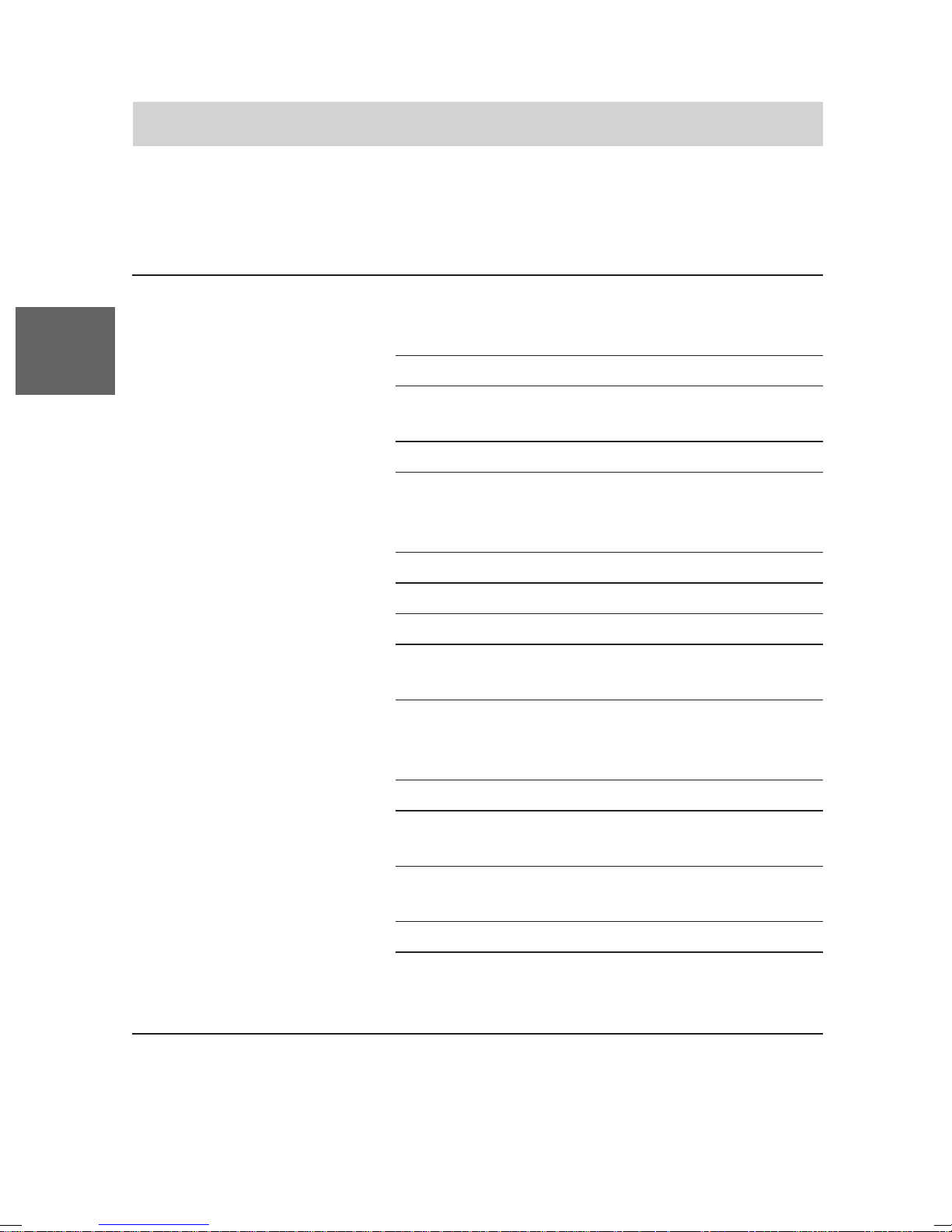
Mobility Server I 33 / CS I55 • I 1/3/5
Technical Specifications / Accessories
Business handset FC1
Not fot use in hazardous areas except zone 2 and zone 22 in accordance
with specifications in the manufacturer’s declarations!
GB
Standard: DECT
TM
(Digital Enhanced
Cordless Telecommunications)
Dimensions: 138 mm x 47 mm x 21 mm plus antenna
Weight, handset: Approx. 109 g
(with rechargeable battery pack)
Battery type: NiMH; 650 mAh
Operating time Conversation: 8 hours
for business handset Stand-by: 80 hours
(with fullbattery):
Charging time: Approx. 5 hours
Frequency range: 1,88 GHz ... 1,9 GHz
Transmitting power: Average value: 10 mW; peak value: 250 mW
Permissible Handset: – 10 °C to + 45 °C
Operating temperature: Charger: + 5 °C to + 40 °C
Storage temperature: – 25 °C to + 55 °C (short-time storage,
up to one month)
0 °C to + 35 °C (long-time storage)
Transport temperature: – 20 °C to + 60 °C
Ringing tone volume
Signalling volume of the 79 dB SPL at a distance of 30 cm from
emergency call tone 1: the acoustic source
Protection category 2: IP 54 (dust-protected and splash-proof)
1
SPL is the abbreviation for the unweighted physical sound pressure level.
2
The protection category IP 54 is effective only as long as the connection
socket for the headset is plugged by the original plastic seal!
74
1
: maximal 81 dB SPL at a distance of 30 cm
from the acoustic source
V 3.5 • 05/2005
Page 75

Mobility Server I 33 / CS I55 • I 1/3/5
Technical Specifications / Accessories
Accessories for the Charger for a FC1 handset
charging set
Other accessories
3
: Plug-in mains unit for continental Europe
Plug-in mains unit for the UK
Charger Plus for a FC1 handset and a
rechargeable spare battery pack
Plug-in mains unit Plus for continental Europe
Plug-in mains unit Plus for the UK
3
: Rechargeable spare battery pack
Carrying bag
Headset (for use with FC1 only)
MEM-Card-Manager
GB
3
Some of the listed accessories must be ordered separately.
V 3.4 • 04/2004
75
Page 76

GB
Messaging on Mobility Server I 33 / CS I55
FC1 Ex (HS) – Explosion-Proof Units
Overview of changes and supplements for explosion-proof versions
FC1 Ex and FC1 Ex HS
Safety instructions
To ensure safe handling of explosion-proof units in hazardous areas, we
have compiled important safety instructions for you. Read and follow these
instructions in any case before entering a hazardous area with an
explosion-protected FC1 Ex (HS).
Commissioning
The battery is attached to the housing with a securing screw. The
FC1 Ex (HS) has its own, specially equipped charger with its own plug-in
power supply unit. Other chargers and plug-in power supply units, e.g.
those designed for the FC1, must not be used for charging the
FC1 Ex (HS).
Making phone calls / Messaging
The operation of the phone and messaging functions is the same for the
versions FC1 and FC1 Ex (HS).
Technical data
The explosion-proof versions FC1 Ex and FC1 Ex HS have a bigger
housing, a slightly higher weight and slightly shorter airtimes and stand-by
times than the Business Handset FC1.
Accessories
As compared with the Business Handset FC1, the explosion-proof
versions FC1 Ex / FC1 Ex HS are equipped with ...
• a special charger, part no. 50 1018 1001, and a corresponding plug-in
power supply unit, part no. 4 999 070 859. A UK plug-in power supply
unit is available for use in Great Britain. Please contact your sales outlet.
• an explosion-proof battery, part no. 50 1014 8000.
• The FC1 Ex must not be operated using a headset. The connection
socket for the headset is sealed by a plastic plug. This plug must not be
removed!
• For the FC1 Ex HS a special headset, order number 50 1010 5101, is
available. Read the safety instructions.
76
V 3.4 • 04/2004
Page 77

Messaging on Mobility Server I 33 / CS I55
FC1 Ex (HS) – Safety Instructions
Instructions and regulations
• All units and batteries carry the CE mark of conformity. In hazardous
areas, only explosion-proof units with the associated explosion-proof
batteries may be used. These units and batteries are provided with an
Ex marking.
• The present instructions will not replace the operating instructions to be
prepared by the operating party.
• The chargers are not explosion-proof and may therefore be
installed and operated only outside of hazardous areas!
Use of units in hazardous areas
Only such units may be operated in hazardous areas which comply with
the basic requirements on safety and health as defined in regulation 94/9/
EC. Explosion-proof units meeting these requirements carry the CE mark
of conformity, followed by the identifier of the referenced agency supervi-
GB
sing the quality assurance system, and the explosion-proof symbol
Hazard degree of hazardous areas
There are hazardous areas (zones) with different hazard degrees. The
units may be operated only in those zones where the hazard degree is not
higher than the one the manufacturer has specified on the unit as unit
group and category. The company operating the units and the Secury
system is responsible for defining these zones.
Batteries for explosion-proof units
Operate explosion-proof units only with suitable explosion-proof batteries
which are approved for the unit! Allowed combinations of units and
batteries can be identified by the information on the unit housing. The use
of other batteries which are not expressly approved is strictly forbidden as
otherwise the operating permit for those units in hazardous areas will
cease due to the lack of explosion protection and the unit will therefore
represent a safety risk!
Allowed combination:
Explosion-proof units may only be operated with the explosion-proof
rechargeable battery part no. 50 1014 8000.
.
77
Page 78

GB
Messaging on Mobility Server I 33 / CS I55
FC1 Ex (HS) – Safety Instructions
Changing batteries, charging batteries
The batteries of the explosion-proof units may be changed only outside of
hazardous areas. The company operating the system and the units is
responsible for performing battery replacements with the necessary care
and for adhering to the safety measures included into the design, i.e. the
correct fixing of the battery using the securing screw. You may never
separate batteries from the unit in hazardous areas. Charge the batteries
only outside of the hazardous areas. Use only the special charger
FC1 S Ex, part no. 50 1018 1001. The use of other chargers is strictly
forbidden as the batteries may overheat and be damaged.
Use of bag; explosion-proof units with and without a clip
If bags are to be used for carrying explosion-proof units in hazardous
areas, you may use two alternatives:
• Use of an explosion-proof unit with the clip mounted, combined with the
bag part number 50 1011 7500
• Use of an explosion-proof unit without the clip mounted, carried in the
bag with the part number 50 1011 7501
Note: Explosion-proof units without the clip mounted may only be taken
in hazardous areas for operation, when beeing carried using the bag part
number 50 1011 7501.
In addition the following requirements must be fulfilled:
1 Only specialists with a profound understanding of explosion protection
are allowed to dismount or mount the clip of an explosion-proof unit.
2 Explosion-proof units without the clip mounted must be inserted into their
bags with the part number 50 1011 7501 prior to be carried into the
hazardous areas.
3 Make sure that explosion-proof units without the clip mounted will not be
withdrawn from their bags part number 50 1011 7501 while still staying in
hazardous areas.
The use of other protective bags is forbidden as they may represent an
explosion hazard.
78
V 3.5 • 05/2005
Page 79

Messaging on Mobility Server I 33 / CS I55
FC1 Ex (HS) – Safety Instructions
Work on the explosion-proof unit
All work on the unit as well as charging and replacing the batteries must
be carried out outside of the hazardous areas. Only qualified persons in
the sense of DIN EN 60079-17 are allowed to open the units.
Setting into operation again after manipulating a unit
All explosion-proof equipment must be repaired by the manufacturer or by
explosion-proof specialists having been skilled by the manufacturer. Any
intervention or repair of this equipment must keep it in compliance with the
prototype test certification documents. Only original spare parts and
accessories from the manufacturer have to be used.
Damaged units
Apparently or only supposedly damaged units must never be taken into
hazardous areas. If an apparently or supposedly damaged unit is in a
hazardous area, it must be switched off immediately and removed from the
hazardous area. Unintended setting into operation must be avoided at any
rate.
Expiry of Ex operating permit (Ex certificate)
Any modification on the unit or on parts of the unit which is not approved
by the manufacturer will void the operating permit. The unit must neither
be carried into hazardous areas nor be operated there.
Use of headset in hazardous areas
GB
The usage of a headset connected to an explosion-proof unit FC1 Ex is
strictly prohibited!
To ensure a proper explosion protection, the socket for connecting a
headset is sealed by a plastic plug. Attention: The Ex certificate for
operation of an explosion-proof handset FC1 Ex in hazardous areas will
become void, if the sealed plug is removed.
The explosion-proof handset FC1 Ex HS may only be used with the
headset order number 50 1010 5101.
The Ex approval of the handset FC1 Ex HS is limited to the protection
against gas explosions. If the handset FC1 Ex HS is used without a
headset, its connection socket for the headset must be plugged by the
original seal. Otherwise the Ex certificate will completely expire.
V 3.5 • 05/2005
79
Page 80
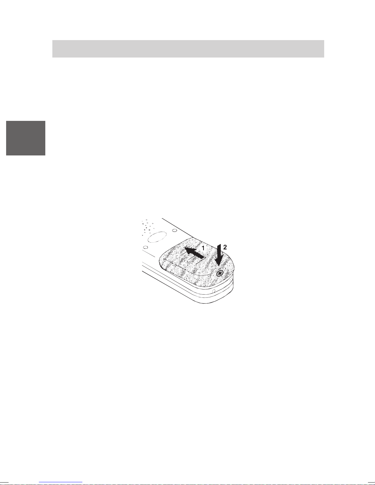
Messaging on Mobility Server I 33 / CS I55
FC1 Ex (HS) – Commissioning
Inserting the MEM card into the FC1 Ex
Inserting the MEM card is as for the Business Handset FC1. See page 47.
Inserting the battery into the FC1 Ex
Caution: Observe the safety instructions for changing the battery of an
explosion-proof handset on page 77/79!
GB
• Push the battery into the housing (1).
• Push the battery down on the screw side until it makes contact with the
housing (2).
• Fix battery with the securing screw (2). Use a screw driver Torx T 10.
The maximum fastening torque of the screw is 60 Ncm. We recomend to
use the screw driver with the part number 50 1010 5300. This screw
driver is also available as a set of five using the part number
50 1010 5400.
Installing the charger FC1 S Ex, part no. 50 1018 1001
(only outside of hazardous areas)
Place the charger on a firm, level surface, e.g. a table. Select a location
outside of hazardous areas which is protected against direct solar
radiation and wetness.
• Plug the plug-in power supply unit into a socket outlet.
• Plug the small connector of the connecting cable into the socket on the
back side of the charger. Note: The Business Handset FC 1 and the
Handset FC 1 Ex are different regarding their housing dimensions and
therefore have different chargers.
The charger is now ready for operation.
80
V 3.5 • 05/2005
Page 81

Messaging on Mobility Server I 33 / CS I55
FC1 Ex (HS) – Commissioning
Charging the FC1 handset
Place the FC1 Ex handset into the charger. A confirmation tone is heard.
The handset remains switched on or off, depending on its status before it
was placed in the charger.
The battery symbol in the symbol line moves until the battery is fully
charged. The batteries get a little warm during the charging process, which
is normal. As soon as the battery is full, trickle charging starts. This is
indicated by a blinking frame of the battery full symbol.
Charging an additional battery
An open bay is provided on the back of the table-top charger FC1 S Ex for
charging a spare battery. Place a battery into the bay with the contacts
facing downward and the securing screw bore facing outside and gently
press it down against the contact springs. As soon as the contact is
established and charging starts, the front bottom LED of the table-top
charger changes its colour from green to red.
GB
Information on the use of the battery
Place the FC1 Ex handset in the charger for at least 14 hours every time
the battery was replaced in order to fully charge the battery. During the
first week of operation, place the handset in the charger after each use.
When new, batteries usually achieve their full capacity only after a few
days of normal use.
You may leave your handset in the charger after use, overnight and during
the weekend. The battery cannot be overcharged.
Do not leave the battery in full solar radiation. Observing these rules will
give you a long time of battery service life.
81
Page 82
Messaging on Mobility Server I 33 / CS I55
FC1 Ex (HS) – T echnical Specifications / Accessories
Handset FC1 Ex / FC1 Ex HS (explosion-proof versions)
GB
Standard: DECT
TM
(Digital Enhanced
Cordless Telecommunications)
Dimensions: 141 mm x 47 mm x 25 mm (plus clip)
Handset weight: approx. 140 g (with battery)
Battery type: NiMH; 650 mAh
Handset airtime: Talking: 7 hours
(with full battery): Stand-by: 70 hours
Charge time: approx. 5 hours
Frequency range: 1.88 GHz ... 1.9 GHz
Transmitting power: Average value: 10 mW; peak value: 250 mW
Permissible Handset: – 10 °C to + 55 °C
operating temperature: Charger: + 5 °C to + 40 °C
Storage temperature: – 25 °C to + 55 °C (short-time storage,
up to one month)
0 °C to + 35 °C (long-time storage)
Transport temperature: – 20 °C to + 60 °C
Ringing tone volume 1: maximal 81 dB SPL at a distance of 30 cm
from the acoustic source
Signalling volume of the 79 dB SPL at a distance of 30 cm from
emergency call tone 1: the acoustic source
Protection category IP 65 (dust-proof and protected against
for FC1 Ex 2: water jets)
!
SPL is the abbreviation for the unweighted physical sound pressure level.
2
The protection category IP 65 is effective only with the original plastic
seal sticked to the connection socket for the headset. Do not remove
the plastic seal!
82
V 3.5 • 05/2005
Page 83

Messaging on Mobility Server I 33 / CS I55
FC1 Ex (HS) – T echnical Specifications / Accessories
Protection category IP 54 (dust-protected and splashwater-proof)
for FC1 Ex HS
Accessories 2: Charger FC1 S Ex (part no. 50 1018 1001)
1:
Plug-in power supply unit for continental Europe
Plug-in power supply unit for Great Britain
Rechargeable spare battery pack
Carrying bag
MEM card manager
Headset (part no. 50 1010 5101) for handset
FC1 Ex HS
GB
1
The protection category IP 54 is effective only as long as the connection
socket for the headset is plugged by the original plastic seal!
Attention: If the handset FC1 Ex HS is used without a headset, its
connection socket for the headset must be plugged by the original seal.
Otherwise the Ex certificate will completely expire.
2
Some of the listed accessories must be ordered separately.
V 3.4 • 04/2004
83
Page 84

F
Mobility Server I 33 / CS I55 • I 1/3/5
Remarques importantes
Contenu de ce mode d’emploi condensé
Ce mode d’emploi vous explique comment mettre votre combiné en
service. Toutes les règles élémentaires nécessaires à l’utilisation ainsi que
les fonctions les plus fréquemment utilisées et les réglages les plus
fréquemment choisis y sont décrits.
Vous trouverez une description exhaustive de toutes les fonctions relatives
à l’installation dans le CD-ROM livré avec l’installation. Il vous est possible
de visualiser et d’imprimer le mode d’emploi.
Contenu d’un jeu complet du combiné
Veuillez contrôler immédiatement le contenu d’un jeu complet lorsque
vous recevez l’ensemble de votre FC1 mobile:
• Combiné FC1 avec le mode d’emploi abrégé.
En état de départ d'usine, les combinés antidéflagrants FC1 Ex sont
munis d'un clip monté qui ne doit pas être démonté!
Une exception est expliquée dans la section consignes de sécurité,
utilisation du sac, combinés antidéflagrants avec et sans un clip.
• MEM-Card
• Batterie de rechange. Les combinés antidéflagrant s ne doivent être utilisés
qu'avec la batterie antidéflagrante, numéro de commande 50 1014 8000.
• Chargeur. Les combinés antidéflagrants ne doivent être chargés qu'avec
le chargeur FC1 S Ex, numéro de commande 50 1018 1001.
• Bloc d’alimentation
• Cette notice d’utilisation abrégée
• CD-ROM avec notice d’utilisation détaillée
Vous pouvez acheter séparés toutes les pièces détachées de ce jeu du
combiné.
Lieux d’utilisation du combiné
Le combiné FC1 peut être utilisé au bureau, en plein air ou dans un
environnement poussiéreux. Il appartient à la classe IP 54 et est protégé
contre les projections d’eau et la poussière.
Protégez-vous contre les troubles de l'audition
Ne laissez pas à proximité de votre oreille le haut-parleur du système
mains-libres disposé sur le dos du combiné!
84
V 3.5 • 05/2005
Page 85

Mobility Server I 33 / CS I55 • I 1/3/5
Remarques importantes
Le volume de la signalisation fait plus que 80 dB (A). De là, une distance
trop courte entre le haut-parleur et l’oreille ou une incidence fréquente de
la signalisation peuvent entraîner, pour le système auditif, des dommages
rémanents.
Maniement des batteries
• Utilisez les batteries de façon conforme. Funktel décline toute
responsabilité en cas de dommages dus à une manipulation non
conforme de la batterie. Tenez compte des remarques relatives à la
batterie en page 93!
• Si, dans des cas extrêmes, les batteries présentent des fuites, il faut que
vous vous attendez à ce que des électrolytes ou des gazes s'échappent.
Mettez le combiné hors service et retournez-le au service après-vente.
Des couches blanchâtres sur le boîtier ou sur la batterie ainsi que des
odeurs inhabituels ou âcres indiquent des fuites.
• Protégez-vous contre des brûlures par acide et des empoisonnements
en évitant d'inhaler des gazes qui s'échappent et le contact direct de la
peau avec des batteries non-étanches. Consultez un médecin en cas de
doute!
F
• Retirez les batteries du combiné avant d'envoyer ou d'emmagasiner le
combiné pendant une longue durée afin d'éviter une décharge profonde
et du dommage.
• Ne jetez pas la batterie au feu car elle risquerait d’exploser.
• Afin de prévenir toute blessure ou tout dégât consécutif à un incendie,
veillez à ce que les contacts de la batterie ne puissent pas entrer en
contact avec des objets électroconducteurs et ne soient pa s
courtcircuités.
• Ne jetez pas les batteries usagées avec les déchets domestiques.
Rapportez-les à un centre de collecte de votre commune ou à votre
revendeur afinque les batteries entrent dans un circuit de recyclage
respectueux de l’environnement. Ne mettez au rebut que les batteries
déchargées.
03/2003
85
Page 86

F
Mobility Server I 33 / CS I55 • I 1/3/5
Remarques importantes
Conseil d’entretien concernant les accus NiCd et NiMH
Vous pourrez y lire comment conserver le plus longtemps possible les
performances du bloc d’alimentation. Pour la charge, n’utiliser que
l’armoire de charge conforme au système!
1 Stockés à une température de 0 °C à 35 °C les blocs d’alimentation
vides ou rechargés et sans circuits électroniques incorporés peuvent
être conservés sans dommages pendant une durée assez importante
(plusieurs années). Les accus pleins peuvent se décharger d’eux
mêmes en quelques semaines ou mois. Cette auto-décharge n’est pas
dommageable, car il ne s’agit pas d’une décharge profonde.
2 Les blocs d’alimentation dotés de circuits électroniques (par exemple
circuits de protection anti-déflagration dans les accus EX) se vident peu
à peu complètement, même lorsqu’ils sont séparés du poste, à cause de
la consommation de ces circuits. Cette décharge profonde entraîne des
dommages irréversibles. Afin d’éviter ces dommages en cas de
stockage prolongé, il faut recharger complètement de tels accus avant
de les stocker et les recharger régulièrement tous les trois mois. La
gamme de températures admise pour un stockage prolongé est
également comprise entre 0 °C et 35 °C.
3 Avant d’utiliser des blocs d’alimentation neufs ou sortis du stock il faut,
de façon fondamentale, les recharger sans interruption. Cette obligation
est valable pour des accus dont vous ne connaissez pas l’état de
charge. Les temps de charge sont indiqués dans le manuel d’utilisation.
4 Si vous constatez que des blocs d’alimentation neufs ou sortis du
stockage présentent, après une première recharge, une durée de
fonctionnement beaucoup plus courte que ce qui est indiqué dans le
manuel d’exploitation, procédez à une cure d’accus conformément au
point 8.
5 Recharger les accus vides sans attendre, ou tout au moins les retirer
des postes pour éviter une décharge profonde. Respecter cependant les
particularités de stockage des blocs d’alimentation comportant des
circuits électrique conformément au point 2.
Des blocs d’alimentation vidés se reconnaissent à l’indication „batterie
déchargée / batterie vide“ ou à une baisse des performances du poste.
6 Veiller d’autre part à ce que les accus ne soient constamment pleins.
Pour un poste alimenté par accus cela signifie qu’il ne doit pas être
86
V 3.5 • 05/2005
Page 87

Mobility Server I 33 / CS I55 • I 1/3/5
Remarques importantes
remis immédiatement dans son armoire de charge après quelques
courtes interventions mais doit être laissé en état de marche (stand by)
près de l’armoire de charge pendant une période prolongée (par
exemple une nuit) jusqu’à ce que l’indication „batterie déchargée /
batterie vide“ apparaisse sur le poste. Une décharge et recharge
régulière du bloc d’alimentation empêchent une perte de capacité des
cellules.
7 Eviter le remplacement de routine régulière de blocs d’alimentation à
moitié vides ou presque pleins. Si pour des raisons opérationnelles un
changement de routine des accus est nécessaire, choisir des intervalles
de rechange assez longs de sorte que le bloc d’alimentation soit
suffisamment vide sans menacer le bon fonctionnement de votre poste
(prévoir une réserve opérationnelle).
8 Si, après une utilisation assez longue, l’autonomie des postes après
chaque charge d’accu se réduit considérablement, procéder à une cure
d’accus:
F
Décharger: Utiliser le poste mobile jusqu’à l’apparition de l’indication
„batterie déchargée / batterie vide“.
Recharger: Procéder à une charge de l’accu conformément au manuel
d’exploitation.
Répéter ce cycle de décharge/recharge plusieurs fois. A chaque
recharge l’accu récupère une partie de son ancienne capacité
d’emmagasinage.
9 Les influences néfastes dont Funktel ne peut endosser la responsabilité
et qui concernent la durée de vie des blocs d’alimentation sont les
suivantes:
Froid extrême ou échauffement excessif au stockage ou en exploitation,
Rangement constant dans l’armoire de charge,
Décharge profonde en exploitation ou pendant le stockage.
V 3.5 • 05/2005
87
Page 88

Mobility Server I 33 / CS I55 • I 1/3/5
Remarques importantes
Maniement des chargeurs
• Toutes les prises de courant de sécurité pour les blocs alimentation
doivent se trouver à proximité des chargeurs à connecter et doivent être
accessible à tout moment. Il faut que les prises de courant de sécurité
soient installes de manière réglementaire par du personnel qualifié.
Avant de brancher le bloc alimentation dans la prise: Assurez-vous que
la tension du réseau d'alimentation correspond à celle indiquée sur le
bloc alimentation (p.ex. 230 V, 50 Hz).
• Les chargeurs et les blocs alimentation ne contiennent pas des
composants que vous pouvenz réparer vous-même.
Les réparations doivent être exécutés de manière réglementaire par du
personnel qualifié. Des chargeurs/blocs alimentation défectueux sont á
remplacer par des composants originaux exclusivement, même si ce
n'est que le câble de raccordement qui est endommagé.
F
• Attention! Maniement de blocs alimentation endommagés!
Coupez le circuit de la prise (retirez ou bien déconnectez le fusible du
circuit correspondent) avant d'enlever un bloc alimentation endommagé
mécaniquement de la prise!
Le contact avec des composants vifs peut être mortel!
• Les chargeurs sont conçus pour des locaux de type bureau. Protégez-les
contre la saleté grave, la poussière, l'humidité, et la radiation solaire
directe.
Protéger le combiné contre des interventions et des influences de
l'environnement
• N’ouvrez jamais le boîtier du combiné téléphonique! Vous risqueriez de
l’endommager. Il ne contient aucune pièce que vous puissiez réparer
vous-même.
• Protégez le combiné contre des influences extrêmes de l'environnement
(p.ex. les températures en dehors celles indiqués dans les
caractéristiques techniques et la radiation solaire directe pendant une
longue durée)!
• N'exposez pas le combiné à des champs magnétiques extrêmement
forts, p.ex. à proximité des fours d'induction et d'appareils de soudage
électrique!
88
Page 89

Mobility Server I 33 / CS I55 • I 1/3/5
Remarques importantes
Protéger d'autres équipements contre les dérangements de marche
causés par le combiné
En général, les autres appareils électroniques sont protégés contre les
perturbations électromagnétiques. Un blindage insuffisant de ces appareils
peut toutefois perturber le fonctionnement de votre combiné. Ces
dérangements de marche peuvent être remédiés par une distance
suffisamment grande entre les deux appareils.
Conseils relatifs au lieu d’installation
Utilisez un support antidérapant pour poser votre chargeur, surtout si votre
meuble est neuf ou entretenu avec des produits d’entretien. Les vernis ou
produits d’entretien peuvent contenir des substances qui peuvent attaquer
le revêtement des pieds de votre chargeur. Ceux-ci peuvent ensuite
laisser des traces indésirables sur la surface de vos meubles. Funktel
décline toute responsabilité en cas de dégradations de ce genre.
F
Agrément et conformité général
Au nom de la société Funktel GmbH, nous certifions que le produit FC1
est conforme aux exigences fondamentales et autres prescriptions
correspondantes de la directive 1999/5/EC (R&TTE). Cet appareil est
destiné à être connecté aux interfaces radios (DECT
TM
) d’installations de
télécommunication Funktel et satisfont aux exigences fondamentales de la
directive 1999/5/EC (Equipement de terminaux radio et
télécommunication, R&TTE).
De par sa construction, cet appareil ne saurait être utilisé directement sur les
interfaces de réseaux de télécommunications publics. En cas de problèmes
lors de l’utilisation, veuillez vous adresser à votre revendeur ou au service
après-vente Funktel. V ous pouvez commander la déclaration de conformité
sur l’adresse E-Mail (messagerie électronique) [email protected].
Cet équipement fonctionne selon le système DECT
TM
dans une plage de
fréquences comprise entre 1 880 MHz et 1 900 MHz. Cette plage dans le
plan d’utilisation des fréquences est en premier lieu valable jusqu’en 2008
et sera reconduite en fonction de l’harmonisation européenne.
DECT
TM
est une marque déposé de ETSI
89
Page 90
Mobility Server I 33 / CS I55 • I 1/3/5
Remarques importantes
Autorisation et certificat de test CE de modèle type pour les
appareils antidéflagrants
Pour la protection contre les explosions de gaz selon ATEX, le certificat de
test CE de modèle type TÜV 03 ATEX 2244 X avec l'identification
II 2 G EEx e ib IIC T4
est valable pour une domaine de températures Ta de - 10 °C à + 55 °C.
Pour la protection contre les explosions de poussière selon ATEX, le
certificat de test CE de modèle type IBExU03ATEX1216 X avec
l'identification
II 2 D IP 65 T 80 °C
est valable pour une domaine de températures Ta de - 10 °C à + 55 °C.
F
90
Page 91

Mobility Server I 33 / CS I55 • I 1/3/5
Mise en service
Si votre combiné n’est pas encore monté
Si le combiné n’est pas complètement monté lorsque vous le recevez,
vous devez:
• Insérer la MEM-Card (voir page 85),
• monter la batterie (voir page 85) et
• Ie cas échéant, retirer le film protecteur de l’afficheur.
• Enfin, votre revendeur doit assigner le combiné à votre installation
téléphonique.
Votre combiné est ensuite prêt à fonctionner.
• Maintenant, raccordez le chargeur (voir page 86).
Si votre combiné est déjà complètement monté
Si vous recevez votre combiné complètement monté et qu’il est déjà
assigné à votre installation téléphonique, il ne vous reste qu’à brancher le
chargeur (voir page 86).
MEM-Card
Vous pouvez téléphoner avec votre combiné uniquement lorsqu’une MEMCard y est insérée. Les données importantes de votre combiné telles que
réglages personnels et annuaires s’y trouvent enregistrés. Même si vous
changez de combiné, vous pouvez immédiatement téléphoner grâce à
cette MEM-Card.
Attention!
Observez les consignes de sécurité pour le maniement d'appareils
antidéflagrants sur les pages 116 à 120.
F
V 3.2 • 02/2004
91
Page 92
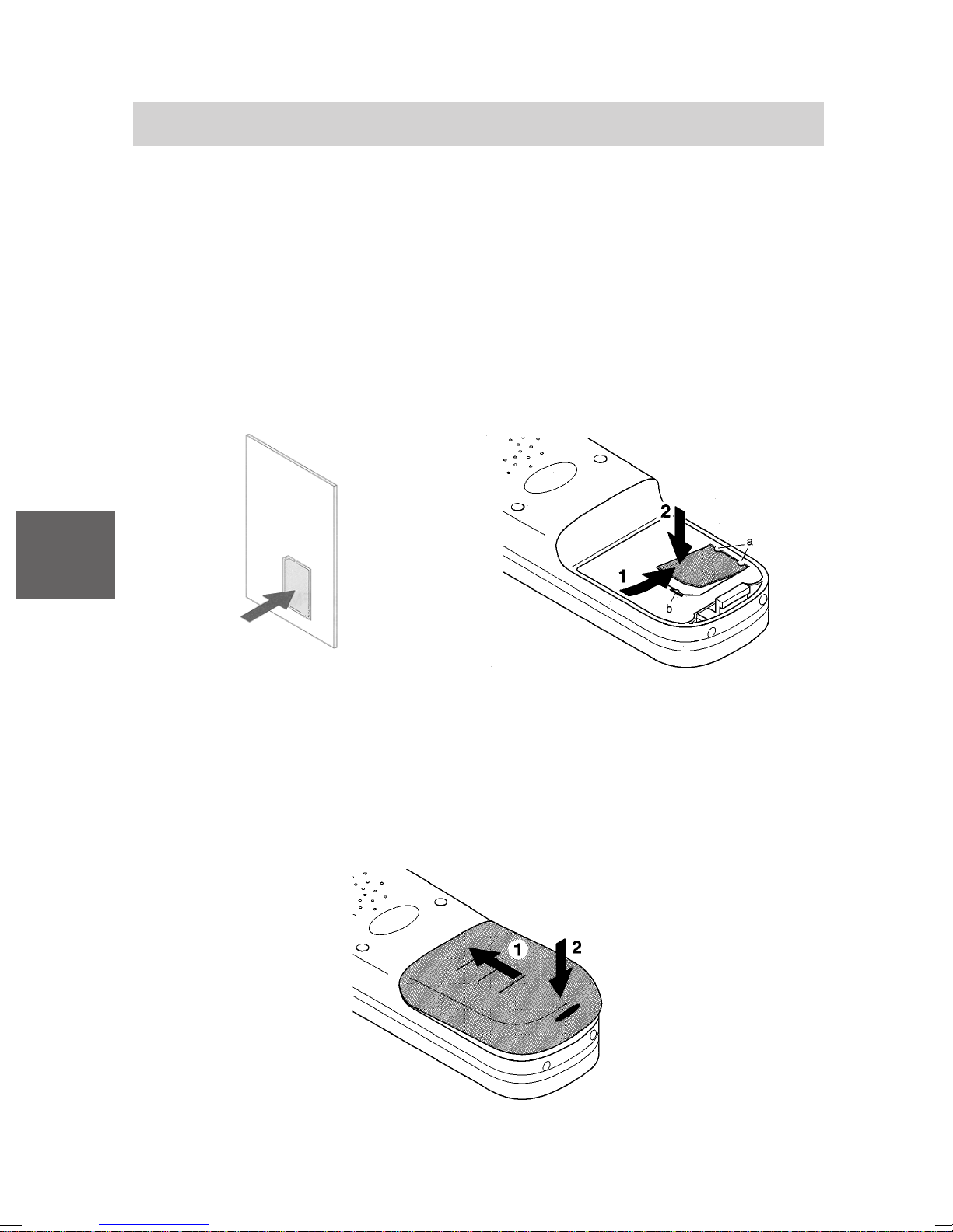
Mobility Server I 33 / CS I55 • I 1/3/5
Mise en service
Insérer la MEM-Card
• Poussez tout d’abord avec le doigt la petite MEM-Card pour l’extraire de
son support (figure ci-contre à gauche).
• Maintenez la MEM-Card inclinée, côté bord moins large et insérez-la en
la faisant glisser sous les onglets de maintien a du compartiment de la
MEM-Card (figure ci-contre à droite) (1). Les surfaces de contact dorées
de la MEM-card doivent être orientées vers le bas.
• Enfoncez la MEM-Card jusqu’à ce que la languette d’arrêt b la bloque (2).
F
Placer la batterie
• Faites glisser la batterie dans le boîtier (1)
• Du côté des saillies de bridage, enfoncez la batterie jusqu’à ce que vous
l’entendiez s’enclencher (2).
92
Page 93
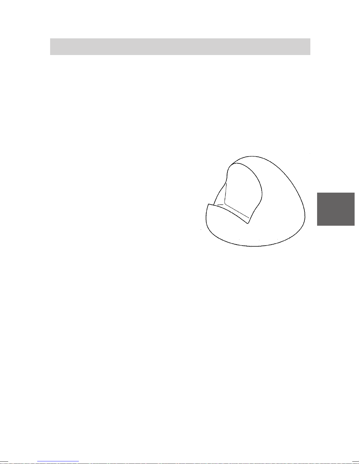
Mobility Server I 33 / CS I55 • I 1/3/5
Mise en service
Installer le chargeur
Posez le chargeur sur une surface dure et plane, p. ex. sur une table.
Choisissez un emplacement à l’abri de l’ensoleillement direct et de l’humidité.
• Raccordez le bloc d’alimentation à une prise de courant.
• Insérez la petite fiche du câble de raccordement dans le chargeur.
Attention: Le Chargeur Plus ne doit être utilisé qu’avec le Bloc
alimentation Plus!
Le chargeur est prêt à fonctionner.
Charger le combiné
Posez simplement le combiné sur le
chargeur. Une tonalité de confirmation
se fait entendre. L’afficheur s’illumine
brièvement.
Le combiné reste activé ou ne se met
pas en marche, en fonction de l'état
avant qu'il a été placé dans le chargeur.
Le symbole de la batterie situé sur la
ligne des symboles se déplace jusqu’à
ce que la batterie soit complètement
chargée. Pendant la recharge, les batteries chauffent légèrement. C’est
normal.
Chargeur
F
Remarques relatives à la batterie
Chaque fois vous avez placé une batterie dans le combiné, effectuez tout
d’abord un chargement complet de la batterie pour au moins 14 heures
sans aucune coupure. Pendant la première semaine d’utilisation, veillez à
replacer régulièrement le combiné dans le chargeur . Les batteries neuves
n’atteignent leur pleine capacité qu’au bout de quelques jours d’utilisation.
Vous pouvez laisser votre combiné pour une durée indéterminée dans le
chargeur. La batterie ne risque pas d’être trop chargée.
Ne laissez jamais la batterie en plein soleil. Elle vous en remerciera par
une longue durée de vie.
93
Page 94
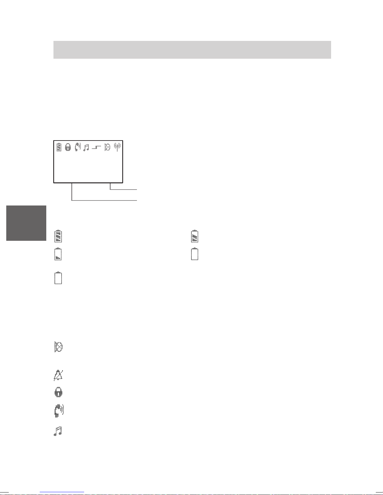
Mobility Server I 33 / CS I55 • I 1/3/5
Afficheur
Les différents textes et symboles qui apparaissent sur l’afficheur vous
aident à utiliser le combiné. Les textes et les symboles vous guident à
travers les menus et vous renseignent sur l’état de votre combiné.
Les fonctions des touches de gauche et de droite changent suivant l’état
actuel du combiné. Elles s’affichent directement au-dessus des touches.
Lignes sur l’afficheur
La ligne des symboles indique l’état actuel du
F
J e a n P e q u e u r
5 3 7 1
C o u p e r M e n u
Légende des symboles
Batterie chargée, Batterie presque chargée,
Batterie presque déchargée, Batterie déchargée,
Le symbole de la batterie clignote: l’autonomie n’est plus que de cinq
minutes!
Tenez compte, s. v . p.: Lorsque vous réinstallez une batterie, le
symbole de la batterie ne s’affiche pas p arce que la situation de la charge
est inconnue. Le symbole apparaît seulement apres que la batterie a été
chargée dans le combiné pour au moins 14 heures sans coupure.
téléphone.
Deux lignes de texte p. ex. pour le nom et le
numéro d’appel.
Fonction de la touche de droite p. ex. Menu.
Fonction de la touche de gauche p. ex. Couper.
Secret: Le microphone est désactivé. Votre correspondant ne peut
pas vous entendre.
Pas de signal d’appel: Le signal d’appel a été désactivé.
Serrure: Le combiné est verrouillé.
Combiné: Le combiné est en communication téléphonique.
Numérotation multifréquences: Chaque pression sur la touche est
transmise sous forme de fréquences audibles à l’usager de cette
communication (post-numérotation multifréquences).
94
Page 95
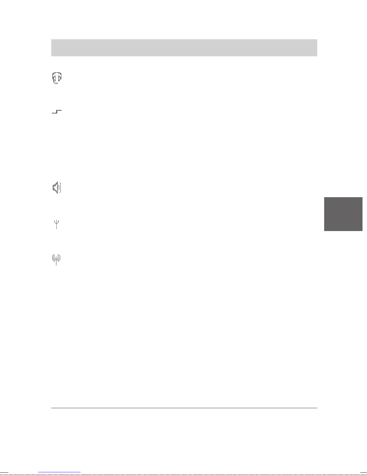
Mobility Server I 33 / CS I55 • I 1/3/5
Afficheur
Combiné écouteur-microphone: vous téléphonez par le biais du
combiné écouteur-microphone. Le microphone et le haut-parleur du
boîtier sont automatiquement déconnectés.
Fonction spéciale1 activée: La touche Etoile a été maintenue
pressée trop longtemps pendant que vous enregistrez un abonné
dans l’nnuaire téléphonique. Chaque pression de touche change
parmi les lettres majuscules et minuscules ... ou
La touche Etoile a été maintenue pressée trop longtemps (jusqu’à ce
qu’un son bas de confirmation résonne) pour activer ou désactiver le
verrouillage du clavier.
Haut-parleur: Le haut-parleur mains-libres situé au dos du boîtier est
activé. Ne laissez pas à proximité de votre oreille le haut-parleur
du système mains-libres! Voir page 84!
Dans la zone de couverture radio de l’installation: Votre combiné se
F
trouve dans la zone de couverture radio d’une base. V ous pouvez
téléphoner .
Liaison avec l’installation: Votre combiné est en communication
téléphonique.
LIST
La liste d’appels comporte au moins une entrée non lue.
MAIL
La liste des messages comporte au moin un message non lu.
mail
La liste des messages comporte au moin un message lu.
mail, LIST
Il y a des messages lus dans la liste des messages et au moins une
entrée non lue dans la liste d’appels.
MAIL, LIST
Il y a au moins un message non lu et un appel non lu.
1
Presser une touche trop lengtemps: Maintenir pressée une touche
jusqu’à un son bas de confirmation résonne!
95
Page 96
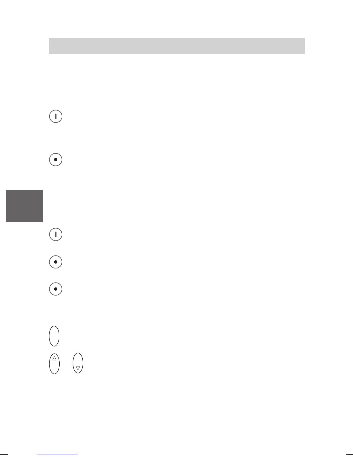
F
Mobility Server I 33 / CS I55 • I 1/3/5
Règles élémentaires d’utilisation
L’utilisation de votre téléphone comporte par un certain nombre
d’opérations qui reviennent fréquemment. Familiarisez-vous avec ces
manipulations.
Activer le téléphone
Le téléphone est désactivé. Pressez longuement la touche
programmable de droite.
Désactiver le téléphone
Le téléphone se trouve à l’état initial. Pressez longuement la
touche programmable de gauche.
Touches (programmables) de gauche et de droite
Les fonctions de ces touches varient selon la situation. La fonction est
toujours indiquée sur l’afficheur au-dessus de la touche, p. ex. Menu ou
Couper.
La touche de droite sert à mettre en marche le combiné ou à
appeler le menu.
La touche de gauche sert à quitter une rubrique de menu ou à
annuler une fonction.
Si dans un menu quelconque vous pressez longuement la touche
de gauche, le combiné revient à son état initial.
Touche OK
O K
O K
Vous clôturez ainsi les procédures de réglage.
O K
ou
Pressez la touche OK vers le haut ou vers le bas pour
sélectionner une rubrique du menu ou un enregistrement dans la
liste des messages ou dans la liste d’appels.
96
Page 97
Mobility Server I 33 / CS I55 • I 1/3/5
Règles élémentaires d’utilisation
Touches à double fonction
Certaines touches de votre combiné disposent d’une seconde fonction.
Vous pouvez les reconnaître à leur surimpression de couleur bleu. Si vous
souhaitez activer la seconde fonction indiquée en bleu, vous devez
pressez longuement la touche. Une tonalité de confirmation basse se fait
entendre.
Sélectionner un menu
Les fonctions et les réglages de votre téléphone sont accessibles par le
menu indiqué sur l’afficheur. Le menu est structuré de telle sorte que la
plupart des rubriques du menu se subdivisent en sous-menus.
Appelez le menu 1 à l’aide de la touche de droite.
ou
O K
Pressez la touche OK vers le haut ou vers le bas et
O K
sélectionnez la rubrique du menu souhaitée, p. ex. Système.
O K
Pressez la touche OK centrique pour sélectionner la rubrique du
menu.
Remonter dans le menu
La touche de gauche vous permet d’accéder à un niveau supérieur
du menu ou de quitter celui-ci.
Sous-menus
Les sous–menus fonctionnent de la même manière que le menu principal.
Annuler
Pressez longuement la touche de gauche pour revenir à l’état
initial.
F
1
Lorsque le combiné se trouve en état initial, vous pouvez directement
presser la touche OK vers le bas pour appeler le menu.
97
Page 98
F
Mobility Server I 33 / CS I55 • I 1/3/5
Règles élémentaires d’utilisation
Verrouiller le clavier à l’aide des touches
R
Ü
touche R.
Désactiver le verrouillage du clavier
Ü
puis la touche R.
Ajuster temporairement le volume du combiné pendant la
communication
L’ajustement du volume initial
au niveau 6 (haut). Voir paragraphe Configurer votre combiné.
Vouz pouvez modifier le niveau temporairement pendant la conversation
téléphonique suivant les besoins:
Pour verrouiller, pressez la touche étoile longuement, puis la
R
Pour le déverrouiller, pressez la touche étoile longuement,
1
du combiné est variable du niveau 1 (bas)
Vous êtes en communication normale ou à mains-libres (avec le
haut-parleur mains-libres activé).
Elever temporairement le volume du combiné
O K
Presser la touche OK vers le haut jusq’à un son bas de confirmation
résonne. Le volume du combiné s’éleve d’un degré. Répétez ce
cours jusqu’à ce que vous avez trouvez le volume désiré.
Réduire temporairement le volume du combiné
O K
Presser la touche OK vers le bas jusq’à un son bas de confirmation
résonne. Le volume du combiné se diminue d’un degré. Répétez ce
cours jusqu’à ce que vous avez trouvez le volume désiré.
Cet ajustement persiste seulement pour la conversation actuelle. Pour la
conversation prochaine l’ajustement du volume initial sera valable pour le
combiné et pour le haut-parleur mains-libres.
1
L’ajustement du volume initial du combiné ne change pas l’ajustement
initial du volume pour le haut-parleur mains-libres.
98
Page 99
Mobility Server I 33 / CS I55 • I 1/3/5
7
P Q R S
Téléphoner comme vous en avez l’habitude
Votre combiné vous permet de téléphoner tout à fait normalement.
Au sein de votre installation téléphonique (communication interne):
Composez directement le numéro de sélection directe à l’arrivée.
En dehors de votre installation téléphonique (communication externe):
Composez le préfixe d’accès au réseau public (zéro le plus souvent) et le
numéro d’appel de votre correspondant.
Appeler
Décrochez.
A B C
1
2
M N O
Composez le numéro d’appel désiré, p. ex. 1276.
6
Mettre fin à la communication
Raccrochez.
Répétition automatique
1
Décrochez.
#
Pressez longuement la touche Dièse.
Recevoir un appel
Votre combiné sonne.
Décrochez.
Nota:
F
Quand vous recevez un message, une conversation existante n’est pas
interrompue. Voir le chapitre Messagerie.
1
Pour Integral 1/3/5, vous pouvez utiliser la fonction de répétition
uniquement pour les appels extérieurs.
V 3.5 • 05/2005
99
Page 100
Mobility Server I 33 / CS I55 • I 1/3/5
Double appel et transfert
Pendant que vous êtes en communication externe, vous pouvez basculer
votre combiné en rétro-appel et converser avec une autre personne. Votre
premier correspondant est alors en attente. – En outre, vous pouvez
transférer l’appelant en interne ou en externe.
Activer un double appel
Vous êtes en communication.
F
R
Pressez la touche R pour mettre votre correspondant en attente.
Votre correspondant ne peut pas vous entendre.
P Q R S
7
M N O
6
J K L
5
G H I
Composez le numéro d’appel désiré, p. ex. 7654.
4
La mention suivante s’affiche: 7654. La communication est en cours
d’établissement. Votre premier correspondant attend.
Revenir en communication avec votre premier correspondant
R
Retournez au premier correspondant à l’aide de la touche R.
T ransférer un correspondant
Vous êtes en communication.
R
7
Pressez la touche R pour mettre votre correspondant en attente 1.
P Q R S
M N O
6
J K L
5
G H I
Composez le numéro d’appel désiré, p. ex. 7654.
4
Raccrochez 2.
1
Pour l’Integral 1/3/5, la communication avec l’usager du rétro-appel est
coupée lorsque vous désactivez le rétro-appel.
2
Vous pouvez effectuer un transfert même si le troisième usager est
occupé.
100
 Loading...