


Wi-Fi RIB™
USER MANUAL
EXPAND YOUR NETWORK
EXPAND YOUR CONTROL
A1848
Wi-Fi RIB™
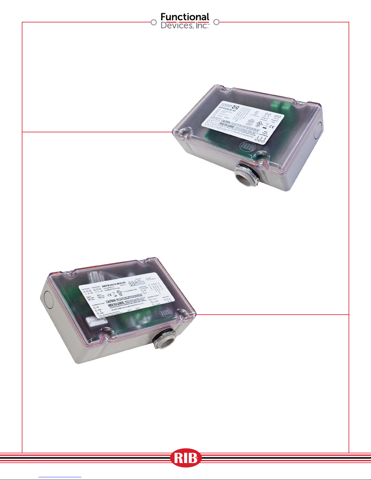
RIBTW24B-WI-N4
What is a Wi-Fi RIB?
Our Wi-Fi RIB is the I/O device for the
next wireless generation of Building
Automation & Energy Management
Systems. The Internet of Things is
happening today and Functional Devices
is proud to introduce their new Wi-Fi RIB,
offering the ability to turn devices on/
off wirelessly, as well as monitor your
network remotely. Our Wi-Fi RIB can be
used in an individual Ad-Hoc setting or
implemented into a much larger Building
Automation System, where many of the
devices can be active.
Why use a Wi-Fi RIB?
As technology continues to move forward
in the wireless applications of Building
Automation & Energy Management
Systems, the more reason to use a
Wi-Fi RIB is evident. By using a Wi-Fi
network, setup can become easier and
less expensive than the traditional hard
wire used in previous networks. By
incorporating our Wi-Fi RIB into your
network, devices can easily be installed in
those hard to get to places—especially for
retrofit applications.
Where would you use a Wi-Fi RIB?
Anywhere in a Building Automation
System or Industrial Control System
where cost reduction and ease of
installation is critical, a Wi-Fi RIB can
be your answer. Whether retrofitting or
with new installation within educational,
medical and commercial/industrial
facilities, a wireless Wi-Fi RIB can do the
job for you.
RIBTW2401B-WIUI-N4
From the design engineering aspect to the
installation of the Wi-Fi RIB, lower cost and
flexibility enables our wireless device to
be the solution. If you want to wirelessly
monitor temperature, humidity or static
pressure, for example, our Wi-Fi RIB is the
solution. If you want the ability to turn
Variable Frequency Drives (VFD) on/off,
again our Wi-Fi RIB is the solution. Even
with external devices such as rooftop AHU
units where energy and installation savings
opportunities are present, let Functional
Devices be your solution.
Is a Wi-Fi RIB secure?
Yes, our Wi-Fi RIB products are secure
within your network. From a network
standpoint, there can be different security
options available, such as
1. A network firewall, where its purpose
is to prevent unauthorized Internet
users from accessing private networks
connected to the Internet. This is where
rules are implemented to restrict
unauthorized Internet users access
to a private network. Typically, these
rules are an IT Systems Administrator
function where he/she has the authority
to make changes to their networks.
2. Also, through a Router and/or Access
Point (AP) where security settings
can be defined with a network name
(SSID), along with the Wi-Fi Protected
Access protocol (WPA2) and security
certification program, a password
must be used for access availability. If
you need assistance, your IT Systems
Administrator can assist with these
settings.
A1848
01
RIBTW24B-WI-N4
On/Off control
throughout network
• Parking Lot Lights
• Air Handling Units
• Unit Ventilators
A1848
RIBTW2401B-WIUI-N4Tur
On/Off/Monitor
Control with results
throughout network
• Temperature
• Humidity
• Current
• Flow
• Pressure
• Level
• Proximity
02
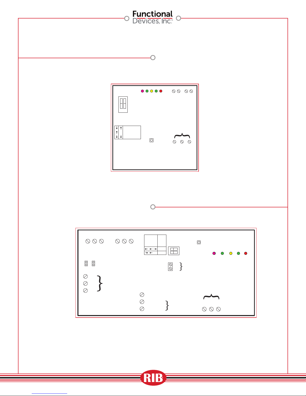
RIBTW24B-WI-N4
IEEEE 802.11 b/g/n compatible (G)
54 Mbps Data Rate
IP Static Address
DIP Switch
CLOSED
Local Relay
Overide
Switch
1 2
OPEN
SW 1XSW 2
Relay State
AUTO
Override ON
Override OFF
Defaults Pushbutton
(Factory settings)
Pink LED = BI Status
Green LED = Device Status
Green LED = Ad-Hoc Status
Yellow LED = Infrastructure Status
RESET to Factory
(Activate with
insulated tool)
Reset Button
Red LED = Relay Status
Digital Input
Input Voltage
BI
BI COM
24 Vac/dc
Relay Contacts
N/C N/O COM
24Vac/dc
Common
Relay Contacts
(1) SPDT 20Amp
Universal Input 1 Universal Input 2
+ 5V UI1 COM
4-20mA ONLY,
when used,
requires jumper
UI1
420
UI2
420
to be installed
Input
Voltage
24Vac/dc
COM
24Vac
24Vdc
IEEEE 802.11 b/g/n compatible (G)
54 Mbps Data Rate
IP Static Address
Universal Inputs (2)
+ 5V UI2 COM
24V Optional
Power Input
Local Relay
Overide Switch
Relay
AUTO
OFF
ON
SW 1
X
SW 2
Term A: (Not used)
Term B: 120 Vac
Term C: Neut
120Vac
Voltage
RIBTW2401B-WIUI-N4Tur
Reset Button
RESET to Factory
Defaults Pushbutton
Operation
Input
(Activate with insulated tool)
General
COM
Purpose
DI
Dry Contact
Input
120 Vac Optional
Power Input
Pink LED = DI Status
Relay Contacts
COM
N/C
N/O
Relay Contacts
(1) SPDT 20Amp
Green LED = Ad-Hoc Status
Yellow LED = Infrastructure Status
Red LED = Relay Status
Green LED = Device Status
A1848
03
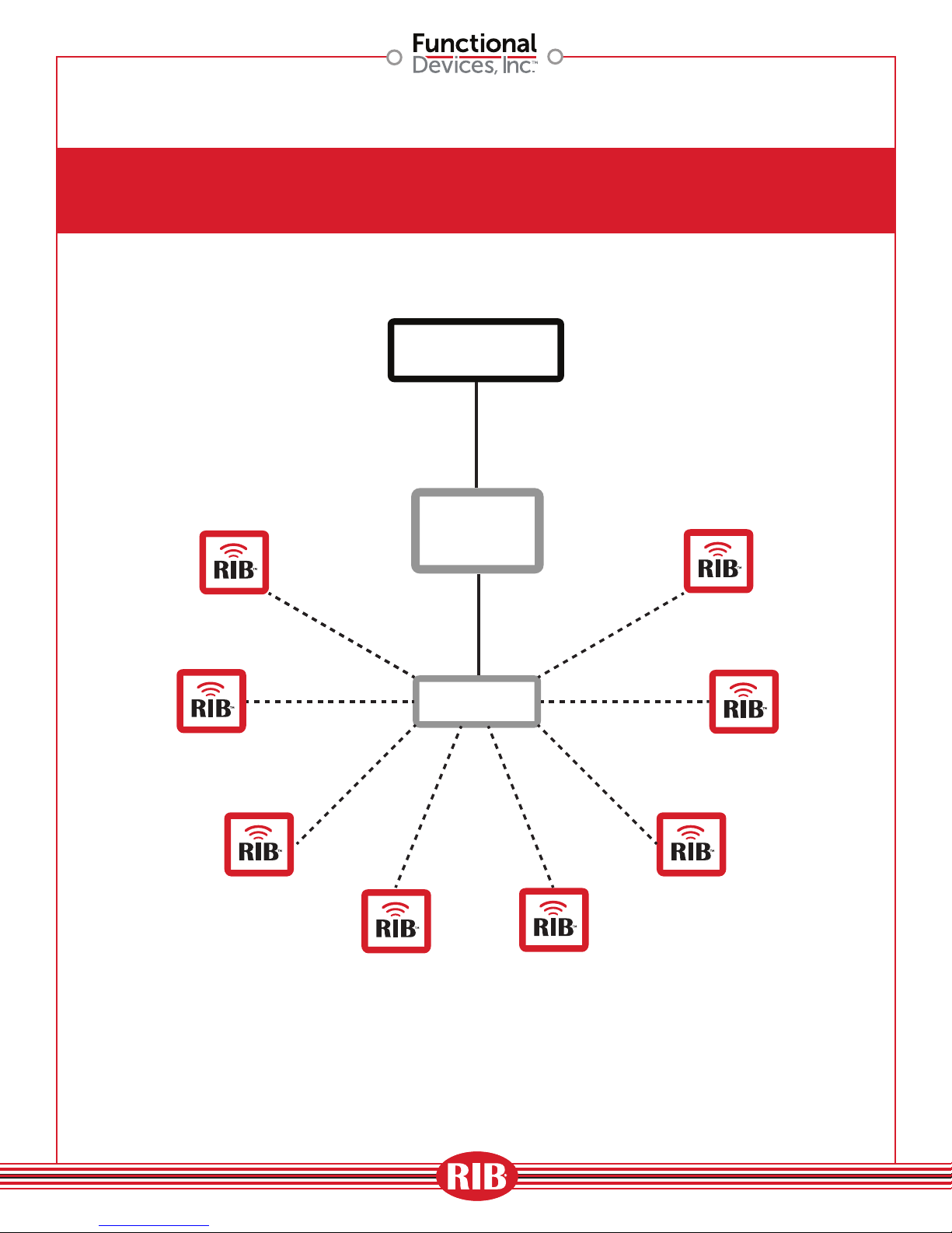
Ad-Hoc Wireless Application
Single Zone Application
BAS
CONTROLLER
A1848
ROUTER
04
Single Wireless Zone Application
(using Gateway)
BAS
CONTROLLER
GATEWAY
DEVICE
A1848
ROUTER
05
Multi-Device/Multi-Zone Application Wireless Zone
BAS
CONTROLLER
ROUTER
BAS
CONTROLLER
GATEWAY
DEVICE
SWITCH
ROUTER
A1848
06

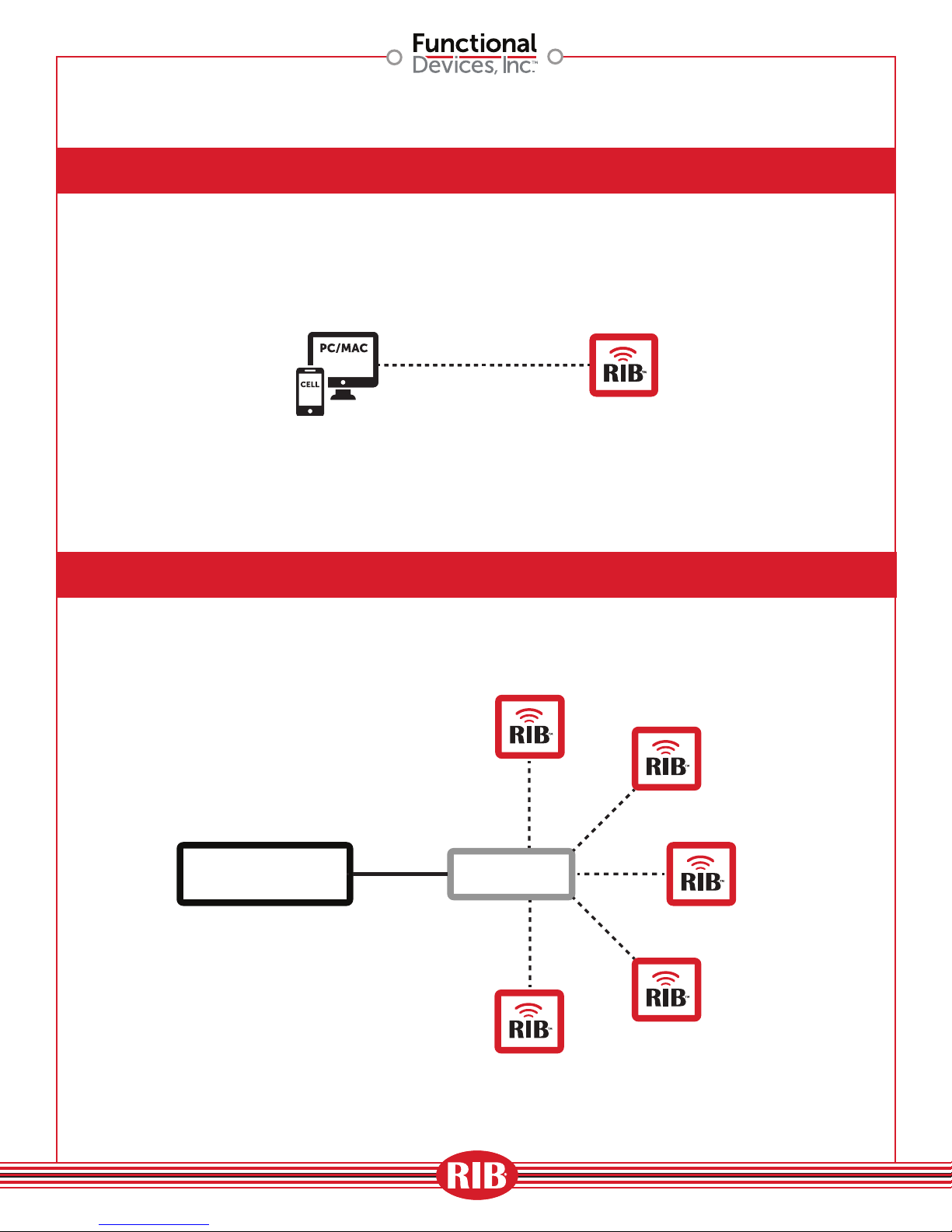
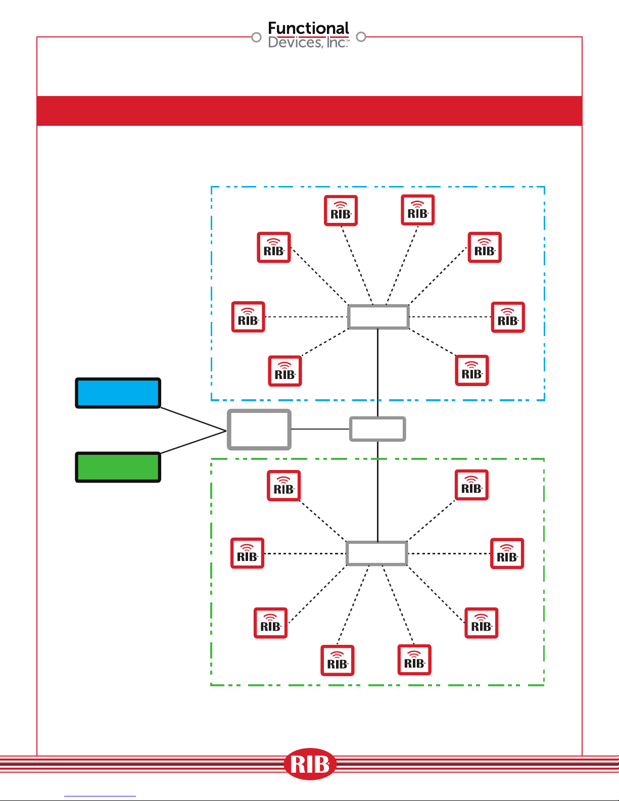
Multi-zone Application
(using Proprietary Software)
ROUTER
ROUTER
ROUTER
SWITCH
Software
Proprietary
Software
ROUTER
ROUTER
SWITCH
ROUTER
A1848
07

Long Distance Control
BAS
CONTROLLER
BRIDGE
(POE)
BRIDGE
(POE)
ROUTER
A1848
08

Energy Savings Application
(Wireless Temperature Control)
PC SOFTWARE
BASED
ROUTER
Unit Ventilators
Classroom
Classroom Classroom Classroom Classroom Classroom
Classroom Classroom Classroom Classroom
ROUTER ROUTER
ROUTER
AP
ROUTER
AP
Wi-Fi RIB Installations
A1848
09
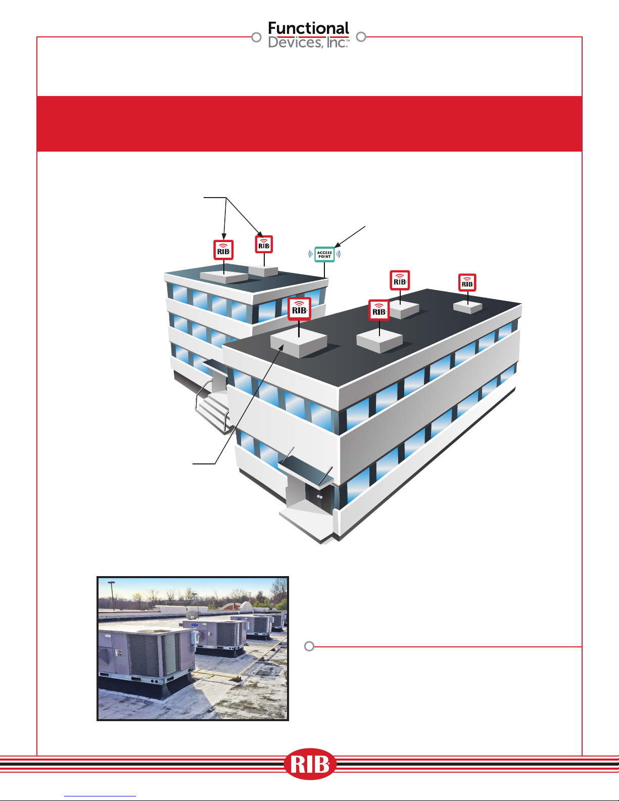
RIBTW24B-WI-N4
Energy Savings Application
(Building Automation System)
Access Point
A1848
Air Handling Unit
Automated Demand Response
“Load Shed Application”
10

Power Input:
Device Settings by Network:
RIBTW24B-WI-N4 BULLETIN
RIBTW24B-WI-N4
Enclosed Wi IEEE 802.11 Network Enclosed I/O Device: One Discrete Output (20 Amp Relay SPDT +
Override), One Discrete Input (Dry Contact, Class 2); 24 Vac/dc
DIP Switch
CLOSED
1 2
OPEN
SW 1
X
SW 2
Relay State
AUTO
Override ON
Override OFF
Pink LED = BI Status
Green LED = Ad-Hoc Status
RESET to Factory
Defaults Pushbutton
(Activate with
insulated tool)
Specications
# Relays & Contact Type:
Expected Relay Life:
Operating Temperature:
Operate Time:
Pink LED:
Green LED:
Yellow LED:
Green LED:
Red LED:
Dimensions:
Approvals:
Housing Rating:
Gold Flash:
Relay Override Switch:
Wi:
Green LED = Device Status
Yellow LED = Infrastructure Status
One (1) SPDT Continuous Duty Coil
10 million cycles minimum mechanical
-30 to 140° F
18ms
Digital Input Status
Wi Ad-Hoc Status
Wi Infrastructure Status
Device Status
Relay Status
4.28˝ x 7.00˝ x 2.00˝ with .75˝ NPT Nipple
UL Listed, UL916, C-UL
FCC, CE, RoHS, Wi Certied ASD Device
UL Accepted for Use in Plenum, NEMA 4
No
DIP Switch Control
IEEE 802.11 b/g/n Compatible, (G)
54 Mbps Data Rate
–95 dBm Min. Sensitivity
+16 dBm Max Output Power
Currently Unsecured Connection
(WPA-PSK or WPA-2-PSK Available)
Supports PING and ARP
DSSS Modulation
BI
BI COM
Red LED = Relay Status
Relay Contacts
N/C N/O COM
Common
24 Vac/dc
Wi-Fi RIB
™
Contact Ratings:
20 Amp Resistive @ 277 Vac
20 Amp Ballast @ 277 Vac
16 Amp Electronic Ballast @ 277 Vac (N/O)
10 Amp Tungsten @ 120 Vac (N/O)
2 HP @ 277 Vac
1 HP @ 120 Vac
Power Input Ratings:
200 mA Max @ 24 Vac
200 mA Max @ 24 Vdc
Available TCP/IP Settings:
•
IP Address (Static)
•
Port Number
•
Subnet Mask
•
Gateway Address
• Ad-Hoc mode
• Infrastructure mode
• Scan for wireless networks
Network Compatible Relay
Shown
With
Cover
Code Version 3.3.9
Device Settings:
•
Local Override
•
Reset to Network Defaults Pushbutton
24 Vac = Terminal Strip (20 Vac min. ; 28 Vac max.)
24 Vdc = Terminal Strip (24 Vdc min. ; 28 Vdc max.)
•
Power up default relay state
•
Host name and location labels
•
Relay bound to digital input
Made in USA
Meets
“Buy American”
of ARRA 2009
A1848 11

RIBTW24B-WI-N4 BULLETIN (CONT.)
Wi-Fi RIB™ – Getting Started
Note: Ad-Hoc Mode must be used for set-up and may be used for permanent use.
1. Make sure laptop IP settings are in DHCP mode.
2. Apply power to the Wi-Fi RIB™ (24Vac or 24Vdc); all settings will be maintained when power is removed. The green Device Status LED will ash at a rate of
once per second and the green Ad-Hoc Status LED will stay lit while in Ad-Hoc Mode, yellow Infrastructure Status LED will remain o while in Ad-Hoc Mode
(see Device LEDs for other LED indications).
3. View Wi-Fi connections on the computer. Look for the network called RIBTW24B-WI-N4 and connect. This establishes a connection between the Wi-Fi
RIB™ and the computer in an Ad-Hoc network.
4. In any Internet web browser, type in the default factory address of 192.168.100.10 and press enter.
Main Page – (Click “Main” link at top of page to return to this page)
In the web browser window, you should see the Wi-Fi RIB™ main web page. You will be able to control the relay and read status. To change the state of the
relay, click the “on” or “o” button and click “Set Relay”. At the bottom of the page you can see: status of relay and last command.
Setup Page – Network and operational settings (Click “Setup” link at top of page.)
Note: Settings can be viewed on Setup Page status or in the xml status page.
1. Change the RIB default IP address, port number, subnet mask, or gateway if desired – click save after all changes are made. After making any changes to
these settings, you will need to reconnect to the RIB at its new address.
Note: The Wi-Fi RIB™ ships from the factory with a default IP address of 192.168.100.10, default gateway of 192.168.100.1, and default subnet mask of
255.255.255.224, and has a unique MAC address for use on the internet or on an internal intranet or network. If at anytime an incorrect address is used or
address is forgotten, the Wi-Fi RIB™ may be returned to factory defaults by pressing the RESET pushbutton on the Wi-Fi RIB™ until the Device Status LED
ashes rapidly (approx. 5 seconds).
2. Set “Device Name” and click save. Set “Device Location” and click save. (Up to 16 characters.)
3. “Default Relay Setting” determines the state to which the relay will default upon return from deliberate power-cycle or due to power loss. Make selection
for relay to come on, stay o, or return to last commanded state. After power-up, the relay will follow commanded states if communications are restored,
unless bound to Digital Input.
4. “General Purpose Digital Input/Relay Binding” allows the relay to be controlled from the Dry Contact GP Digital Input if desired. If bound, the relay will
follow the state of the Digital Input (typical application: motion-detector closes dry contact input, relay turns on light). If unbound, the Digital Input may
be used as a general-purpose status input or otherwise (independent of relay).
Web Page – To enter the Wi-Fi RIB™ into Infrastructure Mode or to return to Ad-Hoc Mode. (Click “Wi” link on top of page)
Note 1: If a mistake is made setting up the Wi-Fi RIB™, it may be necessary to manually return to Ad-Hoc Mode. Pressing the RESET pushbutton (about 5
seconds) on the Wi-Fi RIB™ will return it to factory default settings, including returning it to Ad-Hoc Mode.
Note 2: You may scan for the desired router if in range, or enter the name and security type of the router – the Wi-Fi RIB™ will retain the router information if
power is removed from the Wi-Fi RIB™ and will nd the router once power is restored to the Wi-Fi RIB™ if the router is in range.
1. To scan for routers in range, click “Scan For Wireless Networks” to nd search list of Wi routers of desired infrastructure network and select router.
2. To enter the name and security type of the router, click Other Network, and enter Mode, Network Name, Password Type (WEP, WPA) or no password, then
press Join. The green Ad-Hoc Status LED will extinguish and the yellow Infrastructure Status LED will begin ashing at a rate of once per second until the
Wi-Fi RIB™ establishes connection to router and then stay on (see Device LEDs for other LED indications).
The Wi-Fi RIB™ will be entered into the infrastructure network on the router. You must now go back to view wireless networks on the computer to connect
to the same network to nd the Wi-Fi RIB™. Once the Wi-Fi RIB™ is connected to a router in infrastructure mode, you must connect the laptop or controller
to the same router/network to see and control the Wi-Fi RIB™.
A1848 12
RIBTW24B-WI-N4 BULLETIN (CONT.)
To read status information:
http://192.168.100.10/status.xml
Response will be in the following format:
<?xml version=”1.0” encoding=”utf-8”?>
<response>
<relayState>OVERRIDDEN OFF</relayState>
<lastCommand>OFF</lastCommand>
<digtalInputState>CLOSED</digtalInputState>
<powerOnState>OFF</powerOnState>
<bindingState>UNBOUND</bindingState>
<deviceHostName>Device Name</deviceHostName>
<deviceLocation>Device Location</deviceLocation>
<deviceVersion>v3.3.9 WI</deviceVersion>
<bss>
<valid>0</valid>
<name>0</name>
<privacy>0</privacy>
<wlan>0</wlan>
<strength>0</strength>
</bss>
<scan>0</scan>
<ver>4615</ver>
<count>0</count>
<ssid>WifiRIBsBldg2</ssid> (SSID name of router RIB is connected to)
</response>
RIB Wi-Fi Transmitter
Module Information
Other relay states: OFF, OVERRIDDEN ON, ON, BOUND ON, BOUND OFF
Other network command: ON
Other digital in state: OPEN
Other default power on states: ON, LASTSTATE
Other binding state: BOUND
User defined label
User defined label
Factory firmware version
This equipment has been tested and found to comply with the limits for a Class B digital device, pursuant to part 15 of the FCC Rules. These limits are
This equipment has been tested and found to comply with the limits for a Class B digital device, pursuant to part 15 of the FCC Rules. These limits are
designed to provide reasonable protection against harmful interference in a residential installation. This equipment generates, uses and can radiate
designed to provide reasonable protection against harmful interference in a residential installation. This equipment generates, uses and can radiate
radio frequency energy, and if not installed and used in accordance with the instructions, may cause harmful interference to radio communications.
radio frequency energy, and if not installed and used in accordance with the instructions, may cause harmful interference to radio communications.
However, there is no guarantee that interference will not occur in a particular installation. If this equipment does cause harmful interference to radio or
However, there is no guarantee that interference will not occur in a particular installation. If this equipment does cause harmful interference to radio or
television reception, which can be determined by turning the equipment o and on, the user is encouraged to try to correct the interference by one or
television reception, which can be determined by turning the equipment o and on, the user is encouraged to try to correct the interference by one or
more of the following measures:
more of the following measures:
• Reorient or relocate the receiving antenna.
• Reorient or relocate the receiving antenna.
• Increase the separation between the equipment and receiver.
• Increase the separation between the equipment and receiver.
• Connect the equipment into an outlet on a circuit dierent from that to which the receiver is connected.
• Connect the equipment into an outlet on a circuit dierent from that to which the receiver is connected.
• Consult the dealer or an experienced radio/TV technician for help.
• Consult the dealer or an experienced radio/TV technician for help.
A1848 13

Power Input:
24 Vdc = Terminal Strip (24 Vdc min. ; 28 Vdc max.)
Device Settings by Network:
CAUTION: Remove all connections to UI 1 and UI 2 when setting input.
RIBTW2401B-WIUI-N4 BULLETIN
RIBTW2401B-WIUI-N4
Wi IEEE 802.11 Network Enclosed I/O Device: One Discrete Output (20 Amp Relay SPDT +
Override), One Discrete Input (Dry Contact, Class 2); Two Universal Inputs; 24 Vac/dc, 120 Vac Power
Universal Input 1
+ 5V UI1 COM
UI1
UI2
420
420
COM
24Vac
24Vdc
Universal Input 2
+ 5V UI2 COM
24V Optional
Power Input
Specications
# Relays & Contact Type:
Expected Relay Life:
Operating Temperature:
Operate Time:
Pink LED:
Green LED:
Yellow LED:
Green LED:
Red LED:
Dimensions:
Wires:
Approvals:
Housing Rating:
Gold Flash:
Relay Override Switch:
Wi:
Relay
Operation
AUTO
OFF
ON
SW 1
X
SW 2
Term A: (Not used)
Term B: 120 Vac
Term C: Neut
120 Vac Optional
Power Input
One (1) SPDT Continuous Duty Coil
10 million cycles minimum mechanical
-30 to 140° F
18ms
Digital Input Status
Wi Ad-Hoc Status
Wi Infrastructure Status
Device Status
Relay Status
4.28˝ x 7.00˝ x 2.00˝ with .75˝ NPT Nipple
16˝, 600V Rated
UL Listed, UL916, C-UL
FCC, CE, RoHS, Wi Certied ASD Device
UL Accepted for Use in Plenum, NEMA 4X
No
DIP Switch Control
IEEE 802.11 b/g/n Compatible, (G)
54 Mbps Data Rate
–95 dBm Sensitivity
+16 dBm Output Power
Currently Unsecured Connection
(WPA-PSK or WPA-2-PSK Available)
Supports PING and ARP
DSSS Modulation
Defaults Pushbutton
(Activate with insulated tool)
General
COM
Purpose
Dry Contact
DI
Input
RESET to Factory
Pink LED = DI Status
Relay Contacts
COM
N/C
Red LED = Relay Status
Green LED = Device Status
Green LED = Ad-Hoc Status
Yellow LED = Infrastructure Status
N/O
Contact Ratings:
20 Amp Resistive @ 277 Vac
5 Amp Resistive @ 480 Vac
20 Amp Ballast @ 277 Vac
16 Amp Electronic Ballast @ 277 Vac (N/O)
10 Amp Tungsten @ 120 Vac (N/O)
1110 VA Pilot Duty @ 277 Vac
770 VA Pilot Duty @ 120 Vac
1 HP @ 120 Vac
2 HP @ 277 Vac
Power Input Ratings:
158 mA Max @ 24 Vac
110 mA Max @ 24 Vdc
55 mA Max @ 120 Vac
Available TCP/IP Settings:
•
IP Address (Static)
•
Port Number
•
Subnet Mask
•
Gateway Address
• Ad-Hoc mode (Default)
• Infrastructure mode
• Scan for wireless networks
Network Compatible Relay
Shown
With
Cover
Code Version 3.3.9
Device Settings:
•
Local Override
•
Reset to Network Defaults Pushbutton
24 Vac = Terminal Strip (20 Vac min. ; 28 Vac max.)
120 Vac = Wht/Blk Wire
Neutral = Wht/Yel Wire
• Power up default relay state
• Host name and location labels
• Relay bound to digital input
Made in USA
Meets
“Buy American”
of ARRA 2009
Wi-Fi RIB
™
Universal Input: Congurable by internal device web page, accessible in either Ad-Hoc or Infrastructure.
• Analog value returned, user congurable min. and max. scale, and label, 0-5 Vdc, 0-10 Vdc, or 4-20 mA
• Direct temperature reading from Type T2 Thermistor.
• Digital Input, connect between +5 Vdc and UI input.
4-20 mA, when used, requires jumper to be installed on UI set for 4-20 mA input. Jumper MUST be removed when UI input used as anything other than 4-20 mA.
A1848 14
*

RIBTW2401B-WIUI-N4 BULLETIN (CONT.)
Wi-Fi RIB™ – Getting Started
Note: Ad-Hoc Mode must be used for set-up and may be used for permanent use.
1. Make note of current computer IP settings and restore settings when nished. If you are unsure of settings, contact your network administrator.
2. Make sure computer is set to DHCP mode, then connect to Wi-Fi RIB™ as follows.
3. Connect and apply power to the Wi-Fi RIB™ (24Vac or 24Vdc recommended for setup to avoid Line Voltage wiring; all settings will be maintained when
power is removed.) The green Device Status LED will ash at a rate of once per second and the green Ad-Hoc Status LED will stay lit while in Ad-Hoc Mode,
yellow Infrastructure Status LED will remain o while in Ad-Hoc Mode (see Device LEDs for other LED indications.)
4. View Wi-Fi connections on the computer. Look for the network called “RIBTW2401B-WIUI” and connect. This establishes a connection between the
Wi-Fi RIB™ and the computer in an Ad-Hoc network.
5. In any Internet web browser such as Safari®, Firefox®, or Internet Explorer®, type in the default factory address of 192.168.100.10 and press enter.
Main Page – (Click “Main” link at top of page to return to this page)
In the web browser window, you should see the Wi-Fi RIB™ main web page. You will be able to control the relay and read status. To change the state of the
relay, click the “on” or “o” button and click “Set Relay”. At the bottom of the page you can see: status of relay, last command, universal inputs 1 and 2 and
their associated digital inputs, DI 1 and DI 2 (webpage allows one or both universal inputs to be congured as digital inputs and are usable as such, in additional to the general purpose digital input.)
Setup Page – Network and operational settings (Click “Setup” link at top of page.)
Note: Settings can be viewed on Main Page status or in the xml status page.
1. Change the RIB default IP address, port number, subnet mask, or gateway if desired – click save after each setting.
Note: The Wi-Fi RIB™ ships from the factory with a default IP address of 192.168.100.10, default gateway of 192.168.100.1, and default subnet mask of
255.255.255.224, and has a unique MAC address for use on the internet or on an internal intranet or network. If at anytime an incorrect address is used or
address is forgotten, the Wi-Fi RIB™ may be returned to factory defaults by pressing the RESET pushbutton on the Wi-Fi RIB™ until the Device Status LED
ashes rapidly (approx. 5 seconds).
2. Set “Device Name” and click save. Set “Device Location” and click save. (Up to 16 characters.)
3. “Default Relay Setting” determines the state to which the relay will default upon return from deliberate power-cycle or due to power loss. Make selection
for relay to come on, stay o, or return to last commanded state. After power-up, the relay will follow commanded states if communications are restored,
unless bound to digital input.
4. “General Purpose Digital Input/Relay Binding” allows the relay to be controlled from the Dry Contact GP Digital Input if desired. If bound, the relay will
follow the state of the Digital Input (typical application: motion-detector closes dry contact input, relay turns on light). If unbound, the Digital Input may
be used as a general-purpose status input or otherwise (independent of relay).
5. “Universal Input 1 Setup” and “Universal Input 2 Setup” are used to setup input to analog 0-5 V, 0-10 V, or 4-20 mA; or Thermistor input in Degrees F or C.
Analog inputs use min. and max. of scale and units set by user. Min. and max. are not used when T2 Thermistor selected.
A1848 15

RIBTW2401B-WIUI-N4 BULLETIN (CONT.)
Web Page – To enter the Wi-Fi RIB™ into Infrastructure Mode or to return to Ad-Hoc Mode. (Click “Wi” link on top of page)
Note 1: If a mistake is made setting up the Wi-Fi RIB™, it may be necessary to manually return to Ad-Hoc Mode. Pressing the RESET pushbutton (about 5
seconds) on the Wi-Fi RIB™ will return it to factory default settings, including returning it to Ad-Hoc Mode.
Note 2: You may scan for the desired router if in range, or enter the name and security type of the router – the Wi-Fi RIB™ will retain the router information if
power is removed from the Wi-Fi RIB™ and will nd the router once power is restored to the Wi-Fi RIB™ if the router is in range.
1. To scan for routers in range, click “Scan For Wireless Networks” to nd search list of Wi routers of desired infrastructure network and select router.
2. To enter the name and security type of the router, click “Other Network, and enter Mode, Network Name, Password Type (WEP, WPA), then press Join”.
The green Ad-Hoc Status LED will extinguish and the yellow Infrastructure Status LED will begin ashing at a rate of once per second until the Wi-Fi RIB™
establishes connection to router and then stay on once completely connected (see Device LEDs for other LED indications).
The Wi-Fi RIB™ will be entered into the infrastructure network on the router. You must now go back to view wireless networks on the computer to connect
to the same network to nd the Wi-Fi RIB™. Once Wi-Fi RIB™ is connected to a router, you must wirelessly connect the laptop or controller to the same
router to see and control the Wi-Fi RIB™ since it’s on dierent network.
Device LEDs – A description of all LED indications
• Green Device Status LED: Flashes at rate of once per second (LED will be on 1/2 second and o 1/2 second). Hesitation in LED may be seen when the
Wi-Fi RIB™ is answering HTTP commands.
• Green Ad-Hoc Status LED: On solid while in Ad-Hoc mode. LED will be o when in Infrastructure Mode.
• Yellow Infrastructure Status LED: Flashes at rate of once per second (LED will be on 1/2 second and o 1/2 second) when Wi-Fi RIB™ is searching for
router either during original connection, after power cycle of router or Wi-Fi RIB™, or network activity intended to disconnect Wi-Fi RIB™. LED will be o
when in Ad-Hoc Mode.
• Pink Digital Input Status LED: On if Digital Input is closed, o if open.
• Red Relay Status LED: On if relay is activated (N/O closed, N/C open), o if deactivated (N/O open, N/C closed).
Sources of Relay Control and Order of Precedence
The relay may be controlled over the Wi network by the web page or HTTP commands, by the general purpose Digital Input (if binding is set to Bound
on the setup page), or manually by the override DIP switches on the Wi-Fi RIB™. The Digital Input (if binding activated) takes precedence over Wi network
commands, the DIP switches take precedence over both the Digital Input (if binding activated) and the Wi network commands.
A1848 16

RIBTW2401B-WIUI-N4 BULLETIN (CONT.)
Wi-Fi RIB™ – Control and Status by HTTP Commands and XML
HTTP Get commands to control relay and get status bypassing Wi-Fi RIB™ webpage. Status returned in XML format.
To turn relay on and o:
http://192.168.100.10/index.htm?relay=on
http://192.168.100.10/index.htm?relay=o
To congure relay power up state:
http://192.168.100.10/cong.htm?pwr=on
http://192.168.100.10/cong.htm?pwr=o
http://192.168.100.10/cong.htm?pwr=last
To congure whether relay is bound or unbound to digital input:
http://192.168.100.10/cong.htm?dry=on
http://192.168.100.10/cong.htm?dry=o
To set name and location:
http://192.168.100.10/cong.htm?host=user dened text* (16 characters max)
http://192.168.100.10/cong.htm?loc=user dened text* (16 characters max)
* Follow standard URL encoding. Avoid non-alphanumeric characters as they may be interpreted as Escape Codes and may cause errors.
To reset device:
http://192.168.100.10/reset.htm
To congure Universal Inputs 1 and 2:
The universal inputs can be set up via 4 dierent methods; manually through the web page via a PC/Smart Phone, sending HTTP GET commands to the
device over the network from a controller, or thru a web browser, or by clicking on predened setup links, similar to bookmarks in a web browser, or clickable links within a Word document.
There are 5 dierent modes that the universal inputs support.
1. di05 – 0-5Vdc input mode with OPEN or CLOSED feedback. If input is less than or equal to 0.5 Volts, the digital input status will show “OPEN”. When the
input voltage is greater than or equal to 4.5 volts, the digital input status will show “CLOSED”. When the input voltage is in between, the digital input status
will show “NULL”.
2. 010 – 0-10Vdc input mode.
3. 420 – 4-20mA input mode – with additional hardware jumper installed.
4. therf – Type 2 thermistor input mode with results in Fahrenheit.
5. therc – Type 2 thermistor input mode with results in Celsius.
Example commands use factory default IP address:
192.168.100.10. If you have changed the IP address
of the Wi-Fi, then use your address in the commands.
The 0-5Vdc, 0-10Vdc, and the 4-20mA inputs all support using minimum and maximum scaling (oating point values), and provide a measurement units
entry eld. i.e. If input is set to 0-5Vdc input, with a minimum scale value of 0.00, and a maximum scale value of 100, with units set to Volts. A 2.5 Volt input
would produce a 50% result. If scales were changed to min of 0, and a max of 5, then a 2.5Vdc input would produce a 2.5Vdc one for one result.
Example usage for setup for UI1 and UI2, via controller, or web browser.
http://192.168.100.10/ cong.htm?ui1=di05&min1=0.00&max1=100.00&unt1=Vdc
http://192.168.100.10/ cong.htm?ui1=therf
http://192.168.100.10/ cong.htm?ui2=010&min2=0.00&max2=10.00&unt2=Vdc
http://192.168.100.10/ cong.htm?ui2=therc
ui1 = Universal Input Mode 1. Set to any of 5 listed modes above
ui2 = Universal Input Mode 2. Set to any of 5 listed modes above
min1 = minimum scale for use with UI1 in oating point format
max1 = maximum scale for use with UI1 in oating point format
min2 = minimum scale for use with UI2 in oating point format
max2 = maximum scale for use with UI2 in oating point format
unt1 = Units used for UI1 – up to 9 characters of text
unt2 = Units used for UI2 – up to 9 characters of text
A1848 17

RIBTW2401B-WIUI-N4 BULLETIN (CONT.)
To read status information:
http://192.168.100.10/status.xml
Response will be in the following format:
<?xml version=”1.0” encoding=”utf-8”?>
<response>
<relayState>OVERRIDDEN OFF</relayState>
<lastCommand>OFF</lastCommand>
<digtalInputState>CLOSED</digtalInputState>
<ui1State>0-5V</ui1State>
<ui1Value>49.85 Percent</ui1Value>
<di1Value>Closed</di1Value>
<ui2State>0-5V</ui2State>
<ui2Value>49.85 Percent</ui2Value>
<di2Value>Closed</di2Value>
<powerOnState>OFF</powerOnState>
<bindingState>UNBOUND</bindingState>
<deviceHostName>Device Name</deviceHostName>
<deviceLocation>Device Location</deviceLocation>
<deviceVersion>v3.3.9 WIUI</deviceVersion>
<bss>
<valid>0</valid>
<name>0</name>
<privacy>0</privacy>
<wlan>0</wlan>
<strength>0</strength>
</bss>
<scan>0</scan>
<ver>4615</ver>
<count>0</count>
<ssid>WifiRIBsBldg2</ssid> (SSID name of router connected to)
</response>
RIB Wi-Fi Transmitter
Module Information
Other relay states: OFF, OVERRIDDEN ON, ON, BOUND ON, BOUND OFF
Other network command: ON
Other digital in state: OPEN
Other Universal Input 1 settings: 0-10V, 4-20mA, T2 ermistor F, T2 ermistor C
Universal Input 1 analog value (scaled by customer) followed by label (entered by customer)
Universal Input 1 DI status (analog range 0-5V must be selected and scale set to 0-5)
Other Universal Input 2 settings: 0-10V, 4-20mA, T2 ermistor F, T2 ermistor C
Universal Input 2 analog value (scaled by customer) followed by label (entered by customer)
Universal Input 2 DI status (analog range 0-5V must be selected and scale set to 0-5)
Other default power on states: ON, LASTSTATE
Other binding state: BOUND
User defined label
User defined label
Factory firmware version
This equipment has been tested and found to comply with the limits for a Class B digital device, pursuant to part 15 of the FCC Rules. These limits are
This equipment has been tested and found to comply with the limits for a Class B digital device, pursuant to part 15 of the FCC Rules. These limits are
designed to provide reasonable protection against harmful interference in a residential installation. This equipment generates, uses and can radiate
designed to provide reasonable protection against harmful interference in a residential installation. This equipment generates, uses and can radiate
radio frequency energy, and if not installed and used in accordance with the instructions, may cause harmful interference to radio communications.
radio frequency energy, and if not installed and used in accordance with the instructions, may cause harmful interference to radio communications.
However, there is no guarantee that interference will not occur in a particular installation. If this equipment does cause harmful interference to radio or
However, there is no guarantee that interference will not occur in a particular installation. If this equipment does cause harmful interference to radio or
television reception, which can be determined by turning the equipment o and on, the user is encouraged to try to correct the interference by one or
television reception, which can be determined by turning the equipment o and on, the user is encouraged to try to correct the interference by one or
more of the following measures:
more of the following measures:
• Reorient or relocate the receiving antenna.
• Reorient or relocate the receiving antenna.
• Increase the separation between the equipment and receiver.
• Increase the separation between the equipment and receiver.
• Connect the equipment into an outlet on a circuit dierent from that to which the receiver is connected.
• Connect the equipment into an outlet on a circuit dierent from that to which the receiver is connected.
• Consult the dealer or an experienced radio/TV technician for help.
• Consult the dealer or an experienced radio/TV technician for help.
A1848 18
 Loading...