

Functional Devices, Inc. RIBTW24B-WI-N4, RIBTW2401B-WIUI-N4T User Manual
Wi-Fi RIB™
USER MANUAL
EXPAND YOUR NETWORK
EXPAND YOUR CONTROL
A1848
Wi-Fi RIB™
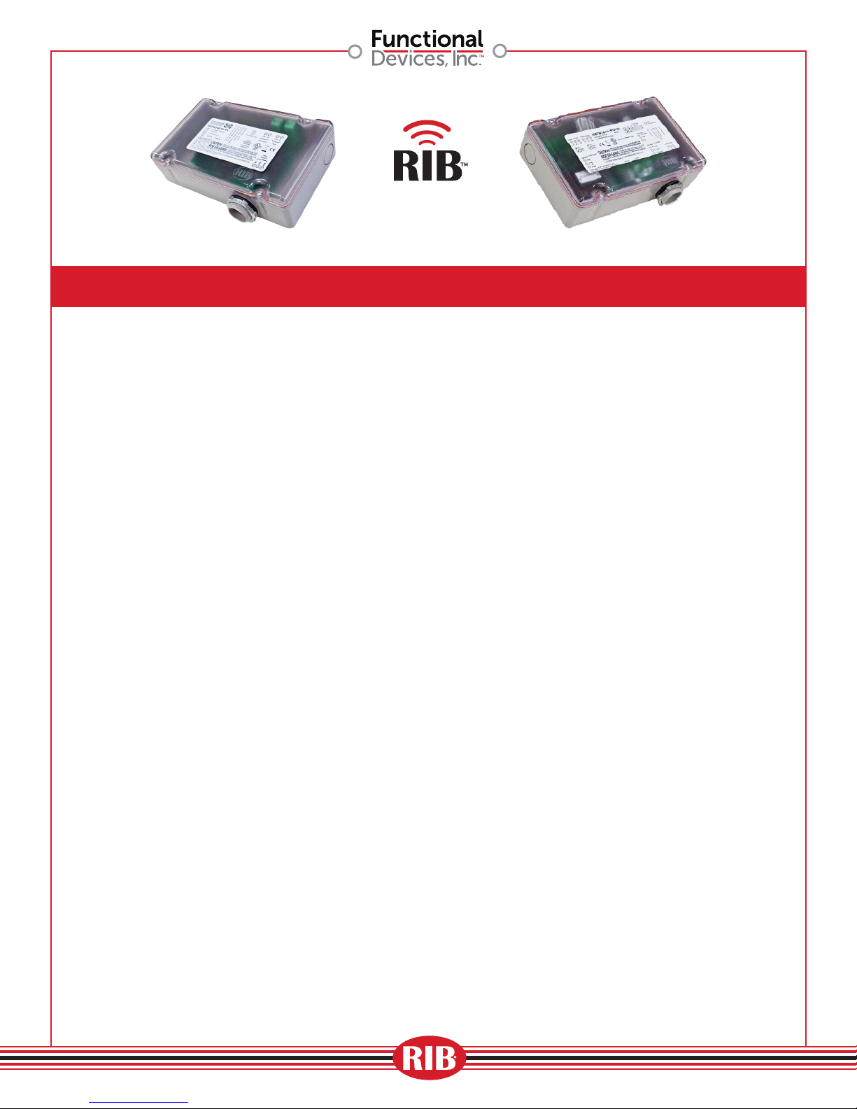
RIBTW24B-WI-N4
What is a Wi-Fi RIB?
Our Wi-Fi RIB is the I/O device for the
next wireless generation of Building
Automation & Energy Management
Systems. The Internet of Things is
happening today and Functional Devices
is proud to introduce their new Wi-Fi RIB,
offering the ability to turn devices on/
off wirelessly, as well as monitor your
network remotely. Our Wi-Fi RIB can be
used in an individual Ad-Hoc setting or
implemented into a much larger Building
Automation System, where many of the
devices can be active.
Why use a Wi-Fi RIB?
As technology continues to move forward
in the wireless applications of Building
Automation & Energy Management
Systems, the more reason to use a
Wi-Fi RIB is evident. By using a Wi-Fi
network, setup can become easier and
less expensive than the traditional hard
wire used in previous networks. By
incorporating our Wi-Fi RIB into your
network, devices can easily be installed in
those hard to get to places—especially for
retrofit applications.
Where would you use a Wi-Fi RIB?
Anywhere in a Building Automation
System or Industrial Control System
where cost reduction and ease of
installation is critical, a Wi-Fi RIB can
be your answer. Whether retrofitting or
with new installation within educational,
medical and commercial/industrial
facilities, a wireless Wi-Fi RIB can do the
job for you.
RIBTW2401B-WIUI-N4
From the design engineering aspect to the
installation of the Wi-Fi RIB, lower cost and
flexibility enables our wireless device to
be the solution. If you want to wirelessly
monitor temperature, humidity or static
pressure, for example, our Wi-Fi RIB is the
solution. If you want the ability to turn
Variable Frequency Drives (VFD) on/off,
again our Wi-Fi RIB is the solution. Even
with external devices such as rooftop AHU
units where energy and installation savings
opportunities are present, let Functional
Devices be your solution.
Is a Wi-Fi RIB secure?
Yes, our Wi-Fi RIB products are secure
within your network. From a network
standpoint, there can be different security
options available, such as
1. A network firewall, where its purpose
is to prevent unauthorized Internet
users from accessing private networks
connected to the Internet. This is where
rules are implemented to restrict
unauthorized Internet users access
to a private network. Typically, these
rules are an IT Systems Administrator
function where he/she has the authority
to make changes to their networks.
2. Also, through a Router and/or Access
Point (AP) where security settings
can be defined with a network name
(SSID), along with the Wi-Fi Protected
Access protocol (WPA2) and security
certification program, a password
must be used for access availability. If
you need assistance, your IT Systems
Administrator can assist with these
settings.
A1848
01
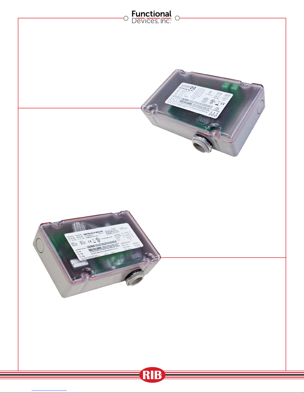
RIBTW24B-WI-N4
On/Off control
throughout network
• Parking Lot Lights
• Air Handling Units
• Unit Ventilators
A1848
RIBTW2401B-WIUI-N4Tur
On/Off/Monitor
Control with results
throughout network
• Temperature
• Humidity
• Current
• Flow
• Pressure
• Level
• Proximity
02
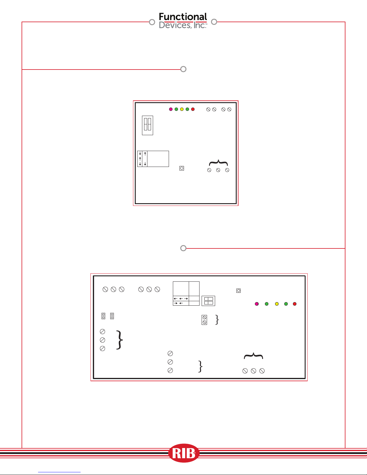
RIBTW24B-WI-N4
IEEEE 802.11 b/g/n compatible (G)
54 Mbps Data Rate
IP Static Address
DIP Switch
CLOSED
Local Relay
Overide
Switch
1 2
OPEN
SW 1XSW 2
Relay State
AUTO
Override ON
Override OFF
Defaults Pushbutton
(Factory settings)
Pink LED = BI Status
Green LED = Device Status
Green LED = Ad-Hoc Status
Yellow LED = Infrastructure Status
RESET to Factory
(Activate with
insulated tool)
Reset Button
Red LED = Relay Status
Digital Input
Input Voltage
BI
BI COM
24 Vac/dc
Relay Contacts
N/C N/O COM
24Vac/dc
Common
Relay Contacts
(1) SPDT 20Amp
Universal Input 1 Universal Input 2
+ 5V UI1 COM
4-20mA ONLY,
when used,
requires jumper
UI1
420
UI2
420
to be installed
Input
Voltage
24Vac/dc
COM
24Vac
24Vdc
IEEEE 802.11 b/g/n compatible (G)
54 Mbps Data Rate
IP Static Address
Universal Inputs (2)
+ 5V UI2 COM
24V Optional
Power Input
Local Relay
Overide Switch
Relay
AUTO
OFF
ON
SW 1
X
SW 2
Term A: (Not used)
Term B: 120 Vac
Term C: Neut
120Vac
Voltage
RIBTW2401B-WIUI-N4Tur
Reset Button
RESET to Factory
Defaults Pushbutton
Operation
Input
(Activate with insulated tool)
General
COM
Purpose
DI
Dry Contact
Input
120 Vac Optional
Power Input
Pink LED = DI Status
Relay Contacts
COM
N/C
N/O
Relay Contacts
(1) SPDT 20Amp
Green LED = Ad-Hoc Status
Yellow LED = Infrastructure Status
Red LED = Relay Status
Green LED = Device Status
A1848
03
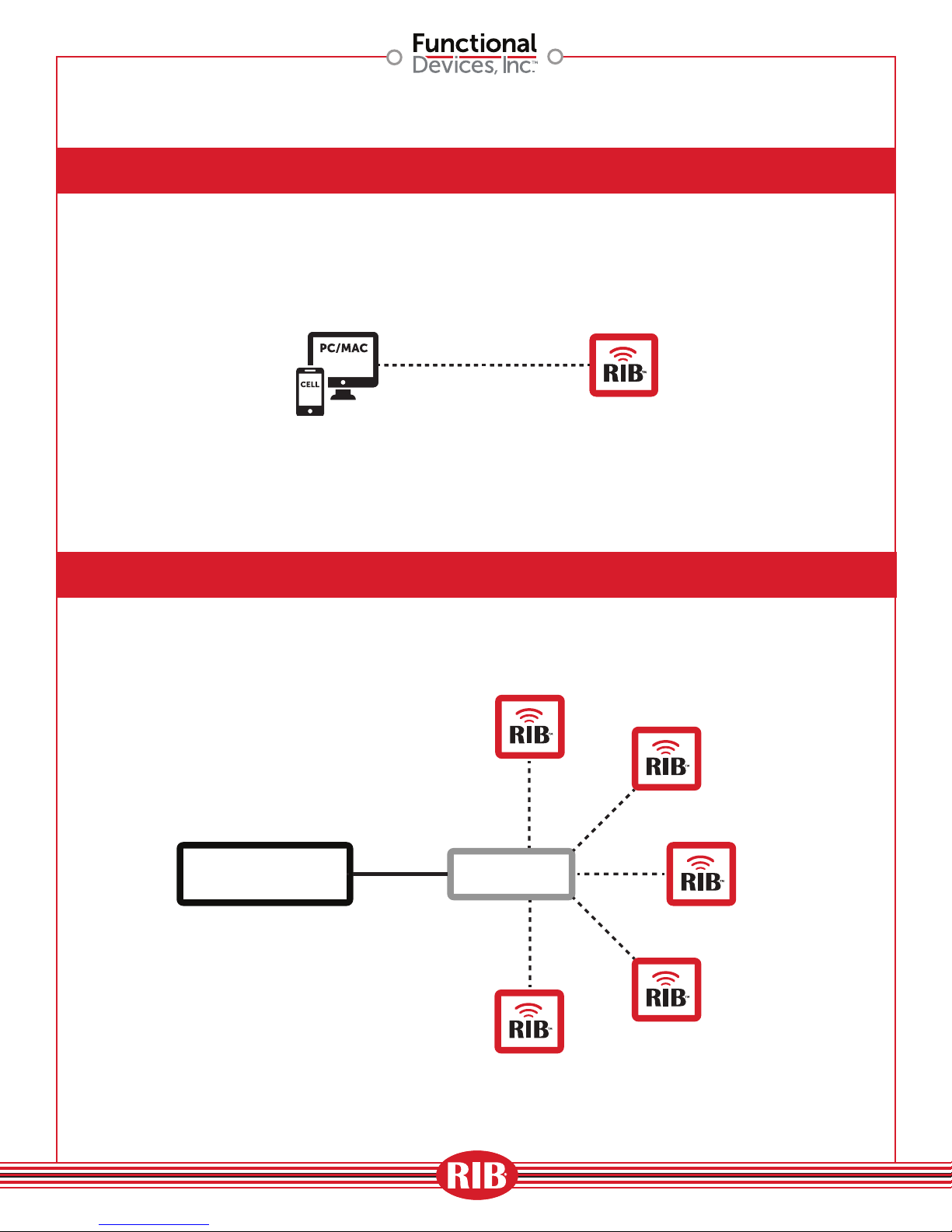
Ad-Hoc Wireless Application
Single Zone Application
BAS
CONTROLLER
A1848
ROUTER
04
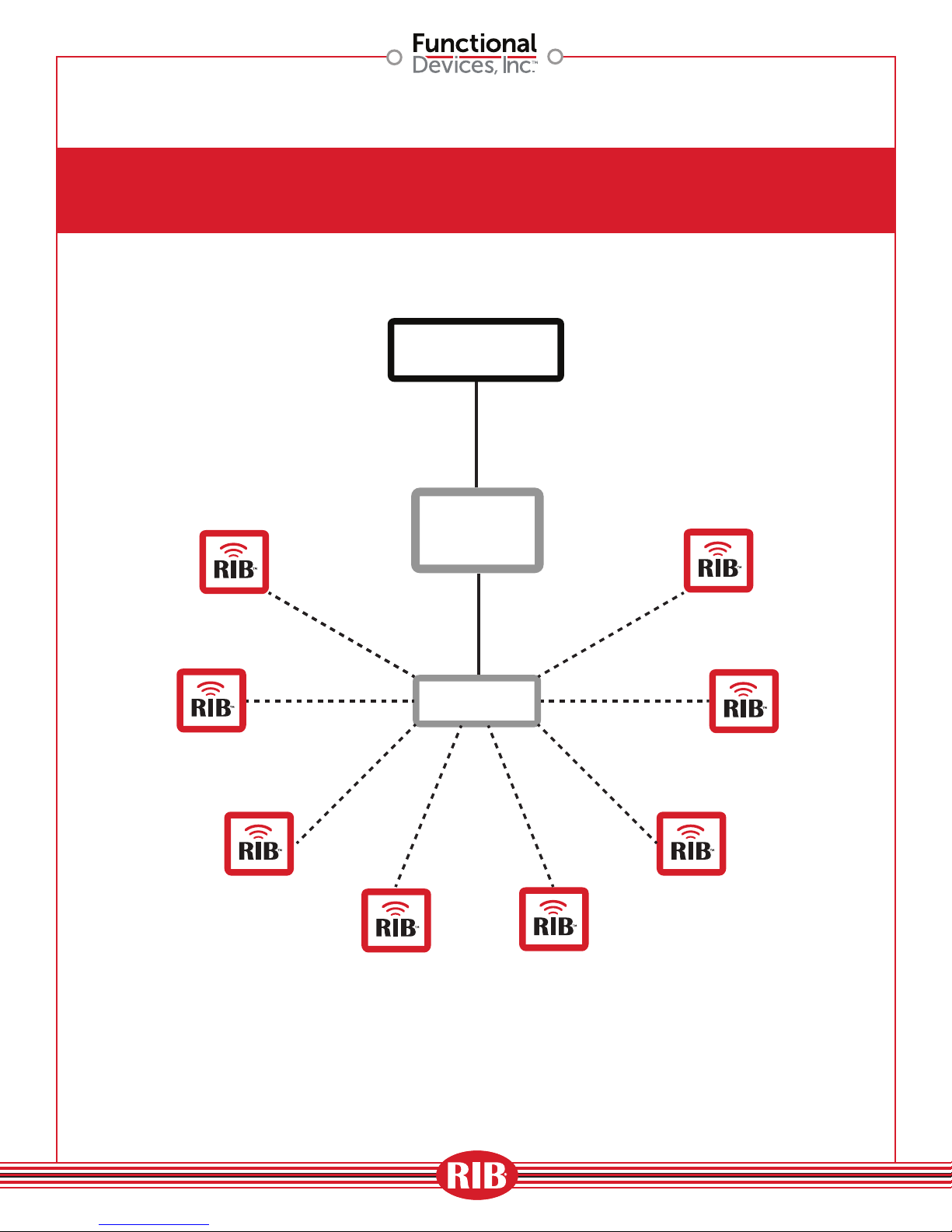
Single Wireless Zone Application
(using Gateway)
BAS
CONTROLLER
GATEWAY
DEVICE
A1848
ROUTER
05
 Loading...